1. Introduction
In recent years, there has been a considerable surge in the popularity of permanent magnet motors. Although magnetic excitation motors have been recognized since the 19th century, a notable proliferation of drives that utilized these motor types did not take place until the 1990s [
1,
2]. Permanent magnet motors, while not a new concept, have undergone significant evolution over time, from DC motors with ferrite magnets to advanced PMSM machines (Permanent Magnet Synchronous Motor) and the ubiquitous BLDCM drives (Brushless Direct Current Motor). This progression would not have been feasible without advancements in power electronics, particularly within control systems, and technological improvements in the production of high-energy magnets from rare-earth sintered materials [
3]. Despite their numerous advantages, such as high efficiency and power density (the ratio of power to machine dimensions), permanent magnet motors also present certain limitations. High-energy permanent magnets are considerably expensive but beyond economic considerations, the primary disadvantage of magnetoelectrically excited motors is the occurrence of electromagnetic torque fluctuations, primarily the result of cogging torque [
2,
4].
Cogging torque is an undesirable phenomenon. Its occurrence is related to an uneven air gap. It creates a braking torque that makes it difficult to start the machine and increases vibration and noise. Therefore, minimization is of paramount importance in the design of machines with permanent magnet excitation, which is the subject of many studies [
5,
6,
7,
8,
9,
10,
11,
12]. The variable gap causes the magnetic circuit to become resistant to change.
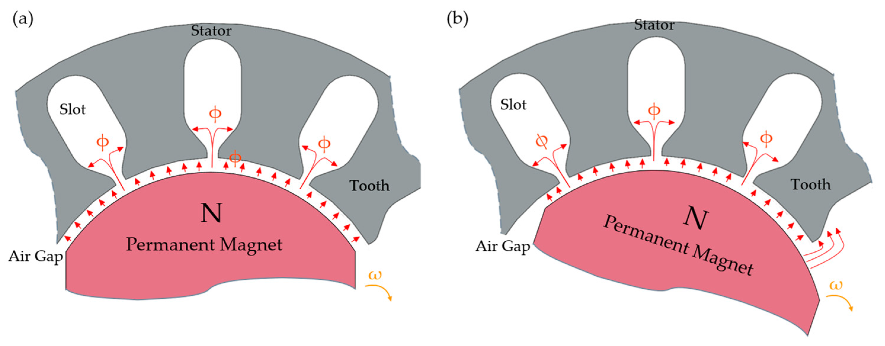
Figure 1 demonstrates the phenomenon associated with the generation of cogging torque in a BLDC motor. This phenomenon occurs in every permanent magnet machine. In
Figure 1a, the alignment of the permanent magnet corresponds to the maximum number of teeth. At this alignment, the force components induced by the magnetic flux negate each other, resulting in the absence of cogging torque. Conversely, in
Figure 1b, the forces derived from the magnetic flux fail to achieve complete balance, leading to the presence of cogging torque. The diagrams presented in
Figure 1 and
Figure 2 are adapted from [
13], with modifications to enhance clarity
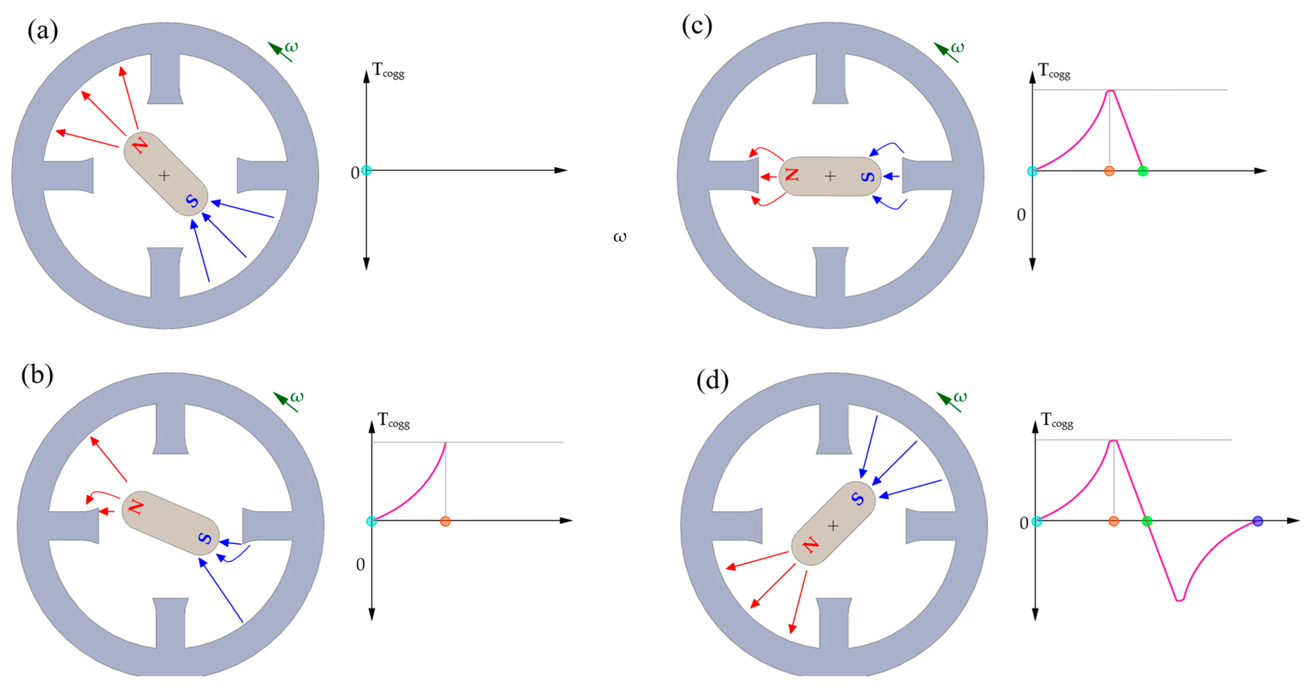
Figure 2 shows the cycle of cogging torque for one period of its variation. The rotor rotates through unstable positions (
Figure 2a,d), where the forces acting on the rotor balance out (zero cogging torque). The rotor, however, will strive for a stable position—the least reluctance of the magnetic circuit. In position 2b, the reluctance forces acting on the rotor do not balance—cogging torque has the highest value.
Cogging torque can be articulated through the following relationship [
14]:
where:
Φ—magnetic flux in the air gap,
Rµ—reluctance of the magnetic circuit (its main part is the reluctance of the air gap reluctance Rµδ),
θr—rotor displacement angle,
Cogging torque is dependent on the magnetic circuit of the motor and generally constitutes a minor percentage, ranging from several to approximately a dozen per cent of the electromagnetic torque of the machine. In the context of low power machines, this value is notably diminutive (significantly less than 1 N·m), thereby presenting challenges in the precise measurement of this magnitude.
The purpose of this article is to present a stand for measuring cogging torque in small electric machines built by the authors. The paper presents a review of devices for measuring torque ripples (including cogging torque)—both commercial and prototypes built in research centers. The concept of the cogging torque measurement stand and its implementation are presented. A comparison of laboratory tests with FEM (Finite Element Method) calculations based on developed field models is provided as a summary of this work.
2. Overview of Solutions for Determining Cogging Torque Value
In the literature, there are many solutions to measure cogging torque [
15,
16,
17,
18,
19,
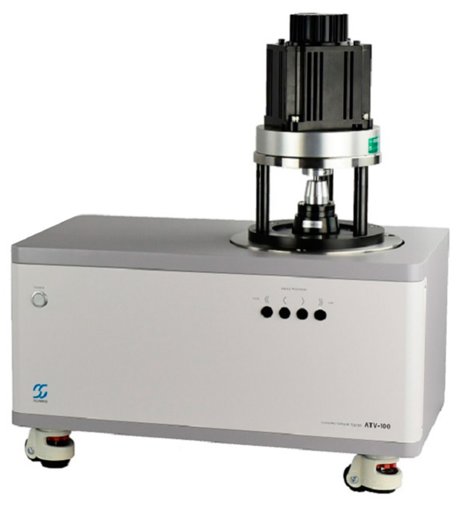
20]. The first group of devices represent a commercial solution produced by companies specializing in the production of measurement devices. Examples of this type of device are the ATM-100 and ATV-100 (which is shown in
Figure 3), manufactured by Sugawara Laboratories Inc. based in Kawasaki, Kanagawa, Japan [
21].
The main advantages of its devices are indicated by Sugawara Laboratories Inc.:
High accuracy—measurement angle resolution 0.01°;
Measures cogging torque without mechanical loss;
Enables measurement of both cogging torque and torque ripple on one piece of equipment;
Short measurement time—measurement speed up to 20 rpm;
Clear presentation of results—XY and Polar Chart, FFT;
Measurement is carried out along the vertical axis, which is intended to facilitate alignment of the motor shaft with the sensor shaft [
21].
The technical parameters of the devices from Sugawara Laboratories Inc. are presented in
Table 1.
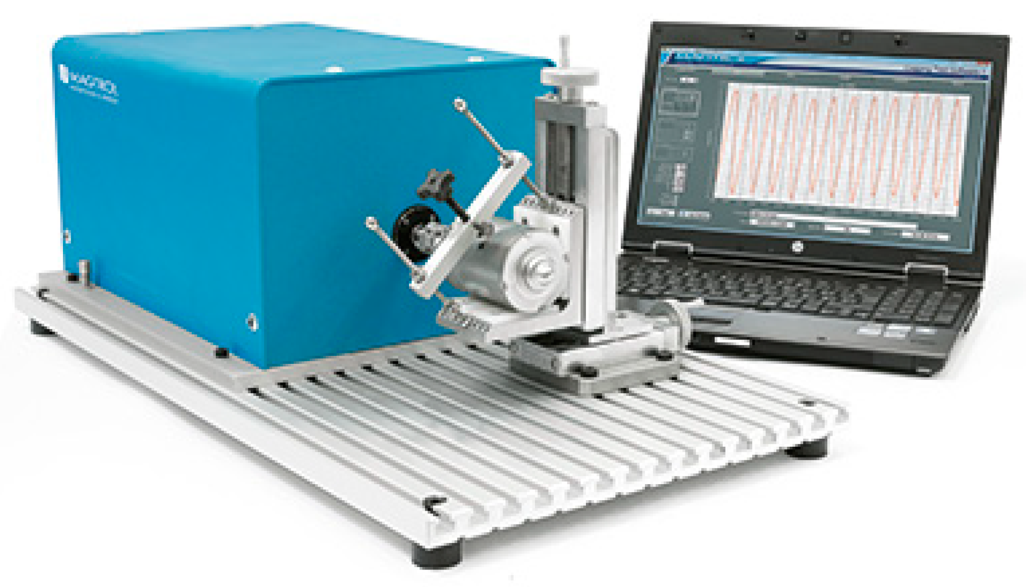
Another group of commercial devices is the Magtrol CTS series device—shown in
Figure 4 [
22]. As declared by the manufacturer, the device has a motor-driven motor and a torque sensor integrated with an encoder. The tested motor is driven by a motor driven motor with a speed in the range of 1–10 rpm. The device allows for measuring cogging torque up to 2 N·m with an accuracy of ±0.1 mN·m. Similarly to the device from Sugawara Laboratories Inc., it makes it possible to determine cogging torque curves as a function of the rotor position (in XY and polar coordinates) and the frequency spectrum (FFT).
Table 2 presents the technical parameters of the devices manufactured by Magtrol Inc., based in Buffalo, NY, USA.
Despite the numerous advantages of the above-mentioned devices, they are very expensive. Their high price makes them unaffordable for many research centers and design offices conducting research on new designs of electric motors with magnetoelectric excitation. Consistent with the above, many researchers try to build their own measurement stations to support their research. In the paper [
23], the authors carried out a measurement using a force meter attached to an arm mounted on the machine shaft to verify the results obtained based on the FEM field models. However, this measurement allowed the authors to estimate the amplitude of cogging torque only roughly. An interesting measurement methodology is presented in the paper [
15]. In this case, the lever mounted on the test shaft was also used for measurements—the measurement instrument of this solution was the digital scale. The scale was mounted on a jack with the help of changing the position at which the coupling torque was determined for different positions of the rotor. Papers [
24,
25,
26] used a method where the measurement was also carried out by means of a balance and a balanced lever attached to the machine shaft, but in these cases the position of the rotor relative to the machine stator was changed by means of a divider of a cutting machine tool. The disadvantage of this solution is that the researcher must manually adjust the position and take a reading from the balance. Taking into account all the inconveniences associated with this, the authors of this article decided to present the concept of an automated station [
2].
It should be noted that, in the initial stages of research, an alternative to performing measurements that allow some estimation of the impact torque value may be to use FEM software and perform calculations based on the field models developed. However, the results obtained in this way are not always reliable for real machines. Field models are developed based on design drawings and material data from the manufacturer. In the paper [
15], the authors point out that due to manufacturing tolerances of stator laminations and rotors, as well as non-uniform magnetization of permanent magnets, it is necessary to determine the full course of this torque as a function of rotor position, as the amplitude of this torque may be different at different rotor positions. Therefore, it should be noted that the field model does not fully reflect the real machine, as it does not take into account the manufacturing tolerances of a given motor sample or the actual parameters of the materials used [
2].
3. Laboratory Stand
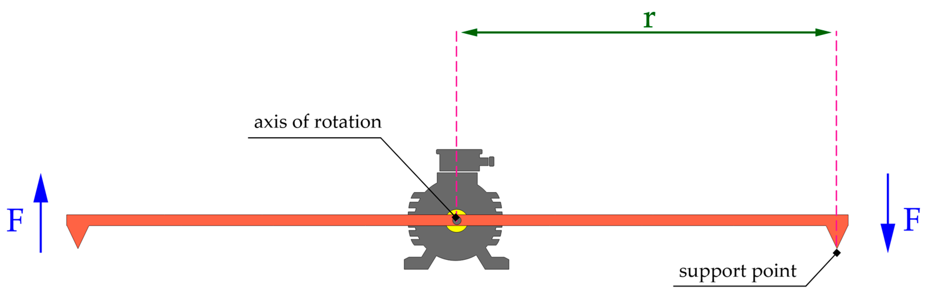
The torque on the machine’s shaft can be successfully determined using a balanced two-armed lever (shown on
Figure 5), where:
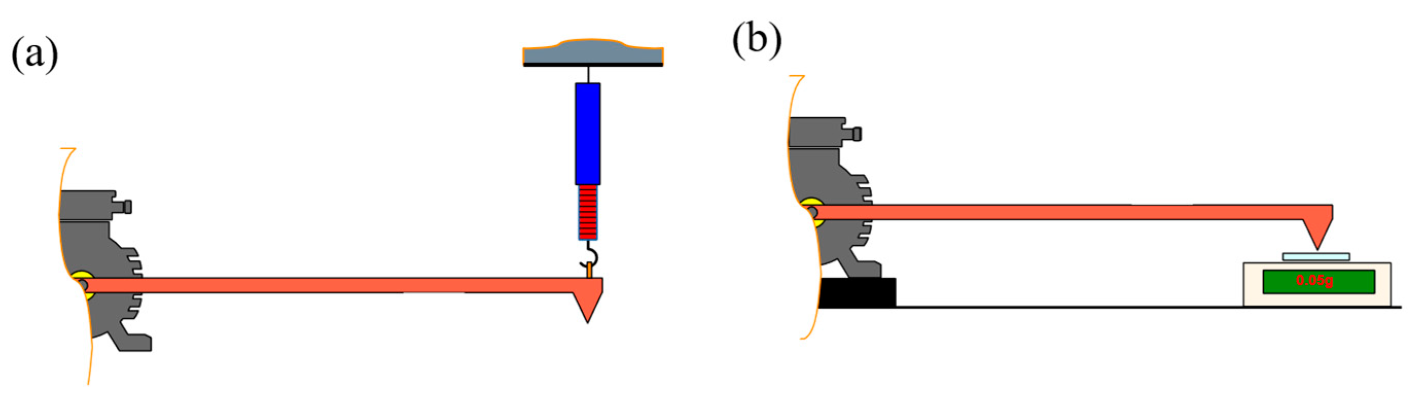
The equilibrium of the levers guarantees the absence of forces other than those exerted by the assessed motor. This measurement technique can be practically employed to ascertain moments of relatively minor amplitude (attributable to the lever’s length), such as bearing thrust torque, friction torque, or cogging torque. Simple measuring devices such as a force meter (value estimate) or precision balance can be used to measure—
Figure 6.
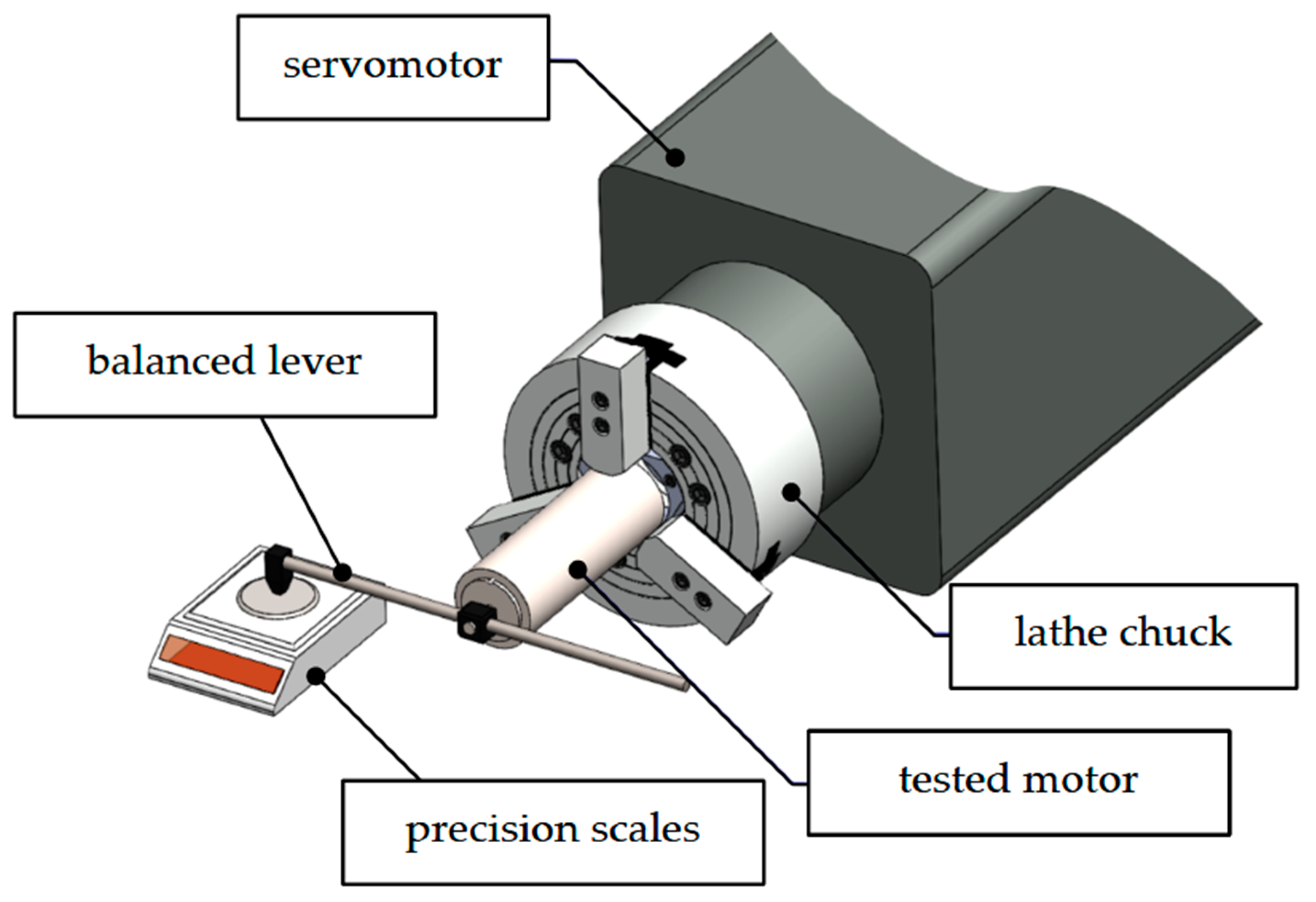
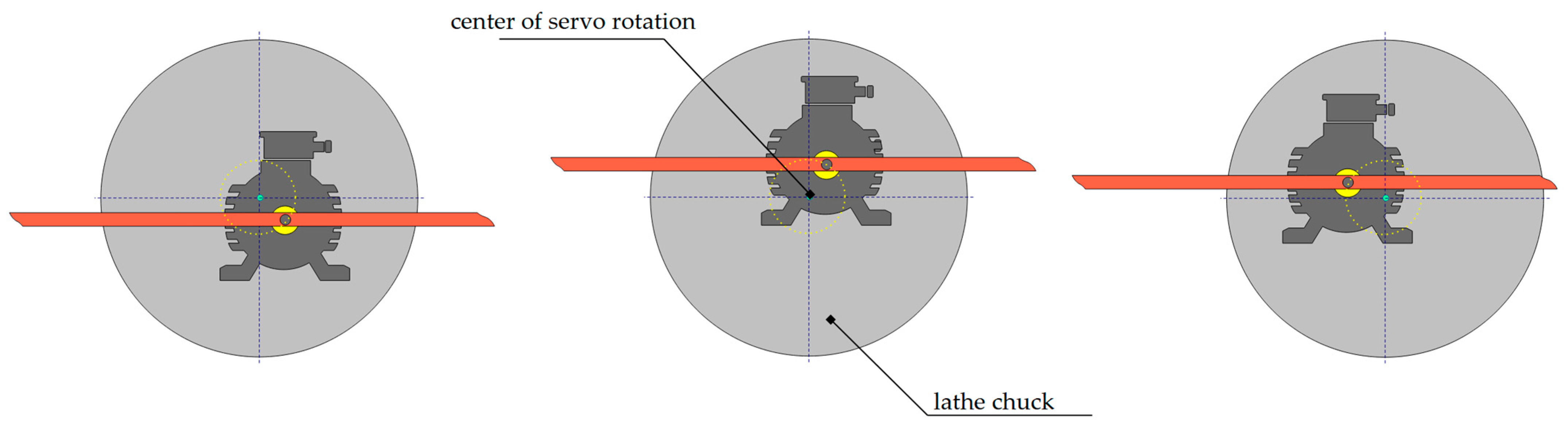
To determine cogging torque for a motor with magneto-electric excitation, measurements must be made for an unpowered machine. In the presented test stand, in order to determine the torque occurring between the stator and rotor, the machine housing was placed in a rotating lathe chuck. The concepts of the test stand are shown in
Figure 7.
The parameters of the components included in the measurement system are shown in
Table 3. The components used in the measurement system are manufactured by companies specializing in drive systems and industrial automation. Delta Electronics, headquartered in Taipei, Taiwan, focuses on power electronics and motion control solutions, while Nidec Corporation, based in Kyoto, Japan, is known for its precision motors and drive technologies.
The motor under test is mounted in a lathe chuck. When the servo drive rotates, the motor shaft with the lever presses on the scale. The value indicated by the scale can be converted to a moment from the equation:
where:
Tmeasure—measure moment,
mscale—mass indicated by the scale,
mload—load mass (weight attached to the lever arm—radius = r),
g—acceleration of the earth,
r—the radius of the lever.
An additional weight attached to the lever allows the measurement of both positive and negative torque values.
The precision of the measurement is contingent upon several factors:
the accuracy of the precision scale,
the exactitude in determining the radius of the lever r,
the assumed value of gravitational acceleration.
For the purposes of calculations, the gravitational acceleration specific to the latitude of Kielce, Poland, was adopted as g = 9.81063 m/s
2). Technical specifications of the scale utilized are presented in
Table 4.
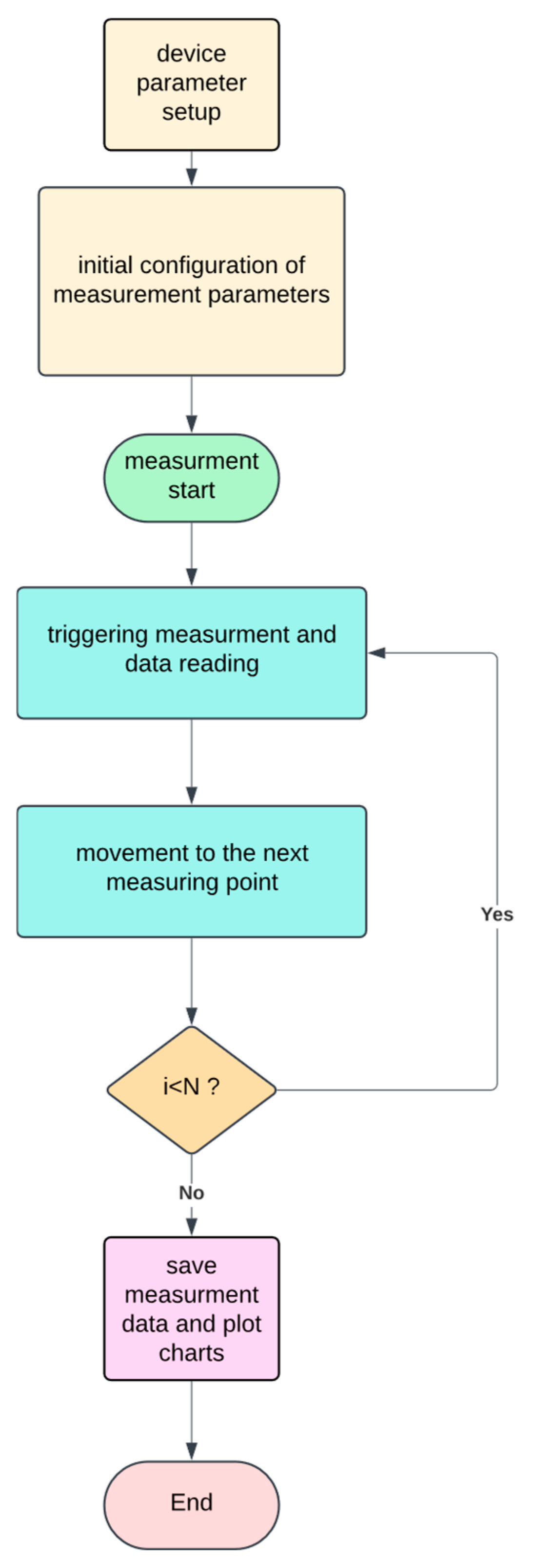
In the test stand built, both the scale and the servodriver communicated with a PC with Matlab/Simulink 2024b environment with Instrument Control Toolboxpackage. Modbus RTU protocol was used to communicate with the servodriver. The scale was connected via an RS232 port and used a simple protocol based on ASCII characters. The measurement cycle is shown in
Figure 8.
The flowchart illustrates a sequential process for conducting measurements using a device. It starts by setting up device parameters, setting measurement settings, and running the measurement cycle until all required points are measured. The process concludes by saving the data and plotting charts.
Measurement process standard operating procedure:
Begin with the device parameter setup.
Perform initial configuration of measurement parameters.
Start the measurement process.
Trigger measurement and read data.
Evaluate if i < N (i.e., if there are more measurements to take):
If Yes, move to the next measuring point and loop back to Step 4.
If not, proceed to Step 6.
Save measurement data and plot charts.
End the process.
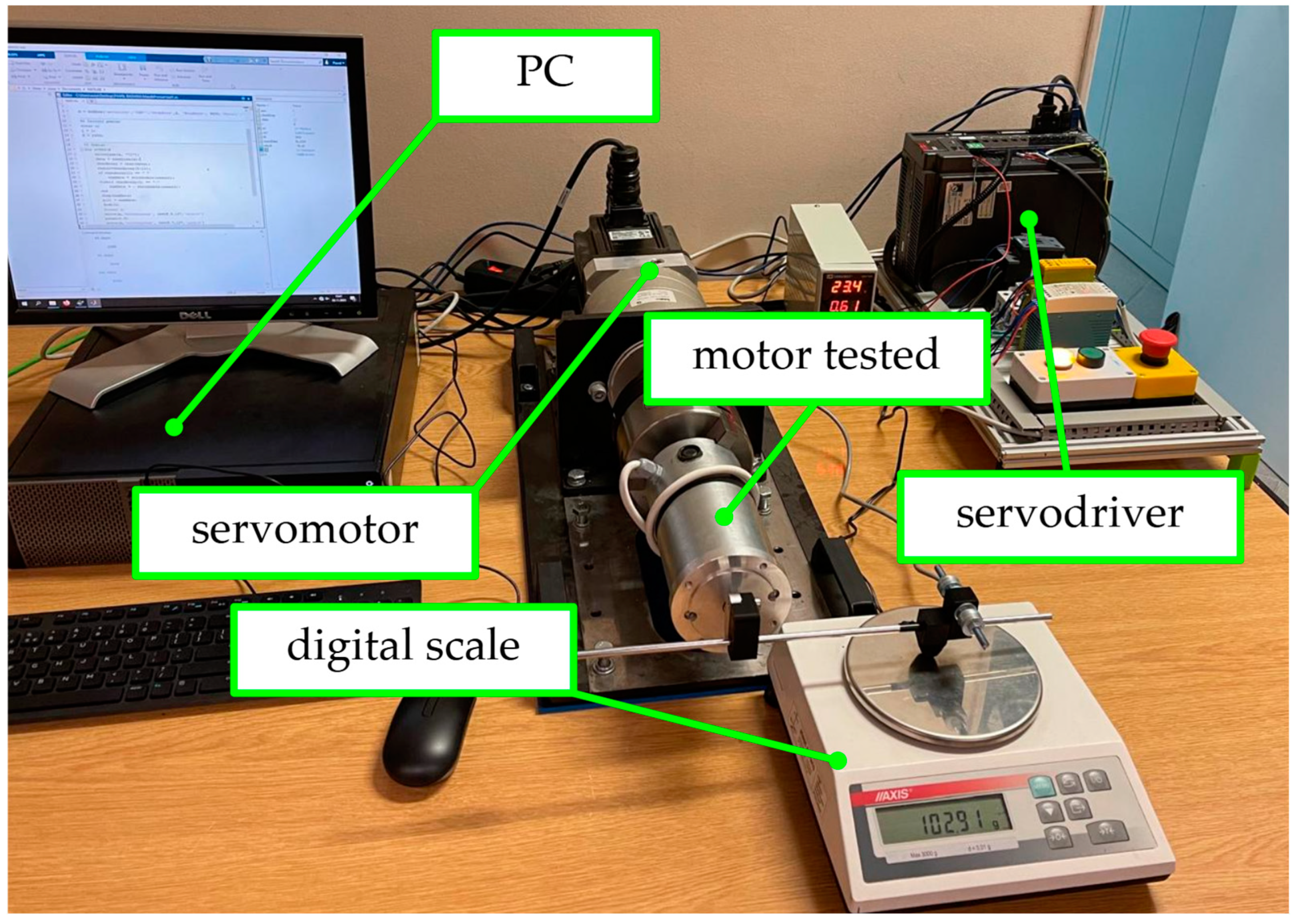
The constructed measurement stand is shown in
Figure 9.
When mounting a motor in a lathe chuck, special attention must be paid to the centricity of the mount—especially for long machines. Proper attachment is facilitated by a three-jawed chuck.
Figure 10 illustrates the motor mount that lacks centricity.
4. Laboratory Test Results
Laboratory tests were conducted for DC commutator motors of the design shown in
Figure 11. The motor has two segmented poles—each has six NdFeB magnets. The packaged stator with magnet slots is locked with screws and non-magnetic sheets. The design of the tested motor is presented in more detail in [
2,
4].
The machines studied are permanent magnet commutator motors with a power of 180 watts. All machines tested have the same stator, which is divided into 12 permanent magnets (as shown in
Figure 11) that form two poles. The motor rotor is equipped with a loop winding of two layers. The rotor configuration for each motor is as follows:
Motor A—15 rotor slot, 0.5 mm gap,
Motor B—16 rotor slots, 1 mm gap.
The prototype of machine A was made with a high degree of care, while the prototype of machine B deviates in parameters from the design data based on which FEA simulations were performed.
To designate the effect of friction of brushes and bearings, the measurement was carried out in three stages:
Measurement for the complete motor,
Measurement for the motor without brushes,
Measurement for a motor without brushes and without a stator.
A comparison of the results of measurements with and without brushes will allow to assess the effect of brush friction on the value of the tested torque. To be able to determine the contribution of bearing—related friction to the measured torque, measurements for a motor without a stator are necessary. The presented machine has a packaged stator that can be easily removed.
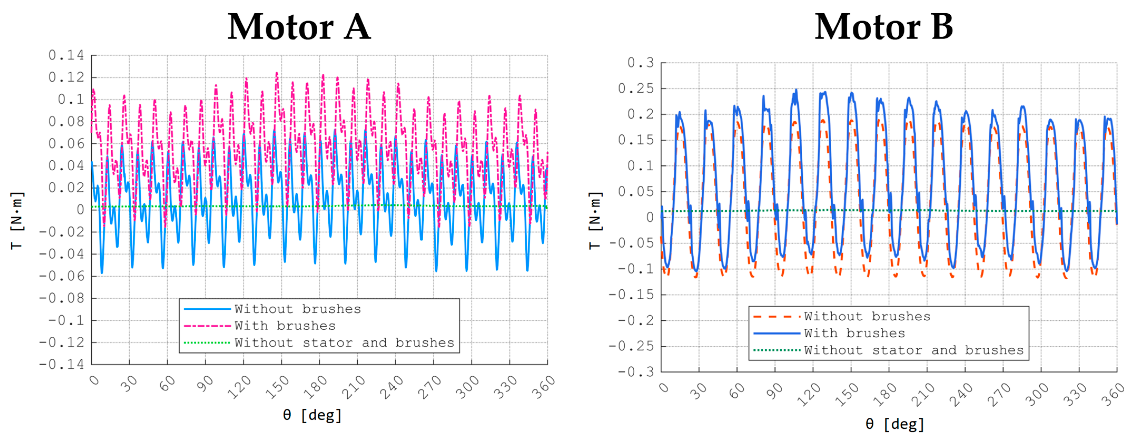
The results shown in
Figure 12 refer to the subsequent stages of the measurement process:
Without brushes—cogging torque + bearing resistance,
With brushes—cogging torque + bearing resistance + brush friction,
Without stator and brushes—bearing resistance.
As depicted in
Figure 12 for Motor B, there is a noticeable discrepancy in the values. It is important to acknowledge that the motor used for measuring bearing friction underwent disassembly and reassembly. Even minor variations in alignment can influence friction, particularly with values of this magnitude. Consequently, the friction measurements with and without a stator do not align.
Figure 13 presents the cogging torques calculated based on measurement results for machines A and B.
Figure 12.
Measured torque values.
Figure 12.
Measured torque values.
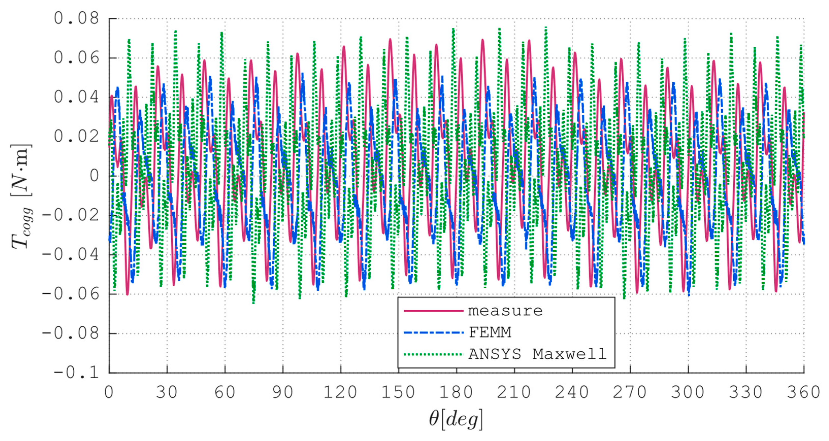
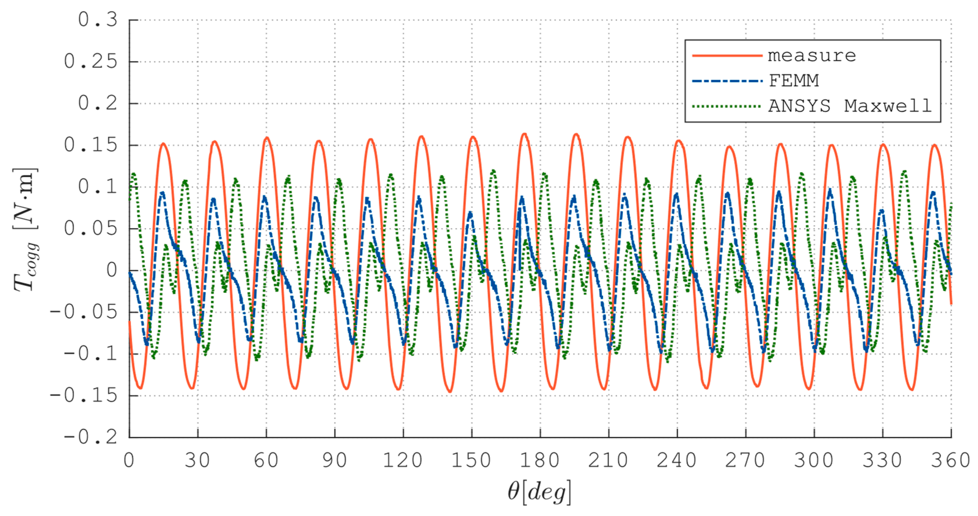
5. Comparison of Results with FEM Calculations
The data obtained during the measurements were compared with the results of the Finite Element Method (FEM) analysis based on the prepared field models. The calculations were carried out in two FEM programs:
The parameters of the field models are presented in
Table 5. Discrepancies between empirical measurements and simulations are evident, as illustrated in the figures. It is imperative to validate the computational outcomes through measurements due to various factors, including but not limited to the precision of the model and the accuracy of the prototype. The prototype of machine A was constructed with a high level of precision in relation to the construction drawings upon which the field models were based- as demonstrated in
Figure 14. In contrast, the manufacturing precision for motor B was comparatively lower, as evidenced by the
Figure 15.
6. Error Analysis
The error of the employed measurement method was evaluated using the principles of error propagation. Cogging torque is calculated as the difference between two measurements:
where:
T1—measured torque with stator (with magnets excitation), including both cogging torque and bearing friction,
T2—measured torque without stator (without magnets excitation), representing only the bearing friction.
The total uncertainty of cogging torque is derived as:
Given that ∆
T1 is significantly larger than ∆
T2 (due to the dominance of
T1 in the measurement process), the total uncertainty can be approximated by neglecting the smaller term, leading to:
This simplification is based on the assumption that T1, which includes both cogging torque and bearing friction, has a significantly larger magnitude compared to T2, which only represents bearing friction. As a result, the uncertainty contribution from ∆T2 is relatively negligible in comparison to. ∆T1 Therefore, the total uncertainty can be approximated ∆Tcogg ≈ ∆T1 without introducing significant error.
For the moment derived from the measurement using relation (2), the total error, in accordance with the principle of error propagation—assuming that the friction within the bearings is sufficiently negligible—is calculated as follows [
27]:
where:
Δmscale—uncertainty of the scale,
Δmload—uncertainty of the load mass,
Δr—uncertainty of the lever arm measurement,
Δg—uncertainty of the assumed value of gravitational acceleration,.
The partial derivatives are as follows:
Assuming that:
The length of the lever was measured with an accuracy of 1 mm,
The local fluctuation of gravity is Δg = ±0.00001 m/s2,
The uncertainties Δmscale and Δmload are derived from the resolution of the scale used in the experiment.
Then for the maximum measured value of cogging torque for machine A:
Therefore, the amplitude of cogging torque for machine A (including the error):
7. Conclusions
In many areas of electrical engineering, experimental studies are necessary due to the accuracy of the description of phenomena and the use of simplified models [
28]. Laboratory measurements of cogging torque on built prototypes are an important step in the design process of permanent magnet electric machines. Cogging torque is particularly important in wind turbines, as it determines the starting conditions. Some estimation at the design stage can be facilitated by calculations for a field model based on the FEM, but as the results of the tests presented in this paper show, the results obtained do not always reflect the actual parameters. Similar conclusions can be found in the work of other researchers [
13]. This is due primarily to the accuracy of the electrical machines but also to the simplifications used in the simulation models analyzed. The measurement of relatively small torque values (especially in low power machines) is sometimes problematic when using classical torque meters. Specialized measurement systems for the determination of cogging torque are very expensive. Therefore, many researchers construct their own measurement systems. Exchange of experience is advisable. The measuring system presented in this paper is based on simple physical relationships. The length of the lever and the weight of the additional weight can be selected individually, as needed. The entire measurement system can be successfully scaled and applied to larger and more complex machines. As the estimated error analysis showed, the results obtained have acceptable accuracy. In order to have confidence in the results obtained in this way, it is necessary to pay attention to several issues. First of all, the axial mounting of the machine under test is extremely important. In addition, especially for measurements of small value, the class of balance used and the accuracy of the lever length measurement are important. A possible direction of further work may be to develop an algorithm for automatic calibration of the device.
Author Contributions
Conceptualization: P.S.; methodology P.S.; software, validation: P.S. and K.B., formal analysis, investigation, resources: P.S., S.R., K.B.; editing, S.R. and K.B.; visualization: P.S., supervision: S.R. project administration: P.S. funding acquisition: S.R. All authors have read and agreed to the published version of the manuscript.
Funding
This research received no external funding.
Data Availability Statement
The original contributions presented in this study are included in the article. Further inquiries can be directed to the corresponding author.
Conflicts of Interest
The authors declare no conflicts of interest.
References
- Bernatt, J.; Gawron, S.; Król, E. Nowoczesne Silniki z Magnesami Trwałymi Do Zastosowań Trakcyjnych. Tech. Transp. Szyn. 2010, 16, 73–76. [Google Scholar]
- Strączyński, P. Analiza Wpływu Wybranych Zmian Obwodu Magnetycznego Na Parametry Silnika Komutatorowego z Magnesami Trwałymi. Ph.D. Thesis, Kielce University of Technology, Kielce, Poland, 2024. [Google Scholar]
- Goryca, Z.; Różowicz, S.; Różowicz, A.; Pakosz, A.; Leśko, M.; Wachta, H. Impact of Selected Methods of Cogging Torque Reduction in Multipolar Permanent-Magnet Machines. Energies 2020, 13, 6108. [Google Scholar] [CrossRef]
- Straczynski, P.; Goryca, Z.; Różowicz, S. Analysis of the Impact of Selected Design Changes on the Cogging Torque of a Commutator Motor with Permanent Magnets. Autom. Elektr. Zakłócenia 2023, 14, 96–109. [Google Scholar]
- Jiang, J.W.; Bilgin, B.; Yang, Y.; Sathyan, A.; Dadkhah, H.; Emadi, A. Rotor Skew Pattern Design and Optimisation for Cogging Torque Reduction. IET Electr. Syst. Transp. 2016, 6, 126–135. [Google Scholar] [CrossRef]
- Dosiek, L.; Pillay, P. Cogging Torque Reduction in Permanent Magnet Machines. IEEE Trans. Ind. Appl. 2007, 43, 1565–1571. [Google Scholar] [CrossRef]
- Wang, K.; Liang, Y.; Wang, D.; Wang, C. Cogging Torque Reduction by Eccentric Structure of Teeth in External Rotor Permanent Magnet Synchronous Motors. IET Electr. Power Appl. 2019, 13, 57–63. [Google Scholar] [CrossRef]
- Li, Q.; Zhang, B.; Liu, A. Cogging Torque Computation and Optimization in Dual-Stator Axial Flux Permanent Magnet Machines. IEEJ Trans. Electr. Electron. Eng. 2020, 15, 1414–1422. [Google Scholar] [CrossRef]
- Goryca, Z.; Paduszyński, K.; Pakosz, A. Model of the Multipolar Engine with Decreased Cogging Torque by Asymmetrical Distribution of the Magnets. Open Phys. 2018, 16, 42–45. [Google Scholar] [CrossRef]
- Zoń, B.; Węgiel, T. Analysis of Cogging Torque Reduction Method Effectiveness on the Example of a Surface Mounted Permanent Magnet Synchronous Motor Model. In Proceedings of the 2018 International Symposium on Electrical Machines (SME), Andrychów, Poland, 10–13 June 2018. [Google Scholar]
- García-gracia, M.; Jimenez Romero, A.; Ciudad, J.; Martín Arroyo, S. Cogging Torque Reduction Based on a New Pre-Slot Technique for a Small Wind Generator. Energies 2018, 11, 3219. [Google Scholar] [CrossRef]
- Pranjic, F.; Virtic, P. Cogging Torque Reduction Techniques in Axial Flux Permanent Magnet Machines: A Review. Energies 2024, 17, 1089. [Google Scholar] [CrossRef]
- Studer, C.; Keyhani, A.; Sebastian, T.; Murthy, S.K. Study of Cogging Torque in Permanent Magnet Machines. In Proceedings of the IAS’97. Conference Record of the 1997 IEEE Industry Applications Conference Thirty-Second IAS Annual Meeting, New Orleans, LA, USA, 5–9 October 1997; IEEE: New York, NY, USA, 1997; Volume 1, pp. 42–49. [Google Scholar]
- Aydin, M.; Qu, R.H.; Lipo, T.A. Cogging Torque Minimization Technique for Multiple-Rotor, Axial-Flux, Surface-Mounted-PM Motors: Alternating Magnet Pole-Arcs in Facing Rotors. In Proceedings of the 38th IAS Annual Meeting on Conference Record of the Industry Applications Conference, Salt Lake City, UT, USA, 12–16 October 2003; IEEE: New York, NY, USA, 2003; Volume 1, pp. 555–561. [Google Scholar]
- Zhu, W.; Yang, Y.; Song, H.; Liu, Y.; Zheng, Z.; Chen, Y. A Novel Cogging Torque Measurement Method for Multi Slot/Pole Permanent Magnet Motor. IET Electr. Power Appl. 2023, 17, 1515–1523. [Google Scholar] [CrossRef]
- Lee, K.; Kim, J.; Lee, Y. A Simple Method of Measuring Cogging Torque in BLDC Motors Using Dynamometer. In Proceedings of the 2018 IEEE International Conference on Consumer Electronics—Asia (ICCE-Asia), Jeju, Republic of Korea, 24–26 June 2018; pp. 206–212. [Google Scholar]
- Zhang, Z.; Zhang, M.; Yin, J.; Wu, J.; Yang, C. An Analytical Method for Calculating the Cogging Torque of a Consequent Pole Hybrid Excitation Synchronous Machine Based on Spatial 3D Field Simplification. Energies 2022, 15, 878. [Google Scholar] [CrossRef]
- Ferraris, L.; Franchini, F.; Poskovic, E. The Cogging Torque Measurement through a New Validated Methodology. In Proceedings of the 2017 11th IEEE International Conference on Compatibility, Power Electronics and Power Engineering (CPE-POWERENG), Cadiz, Spain, 4–6 April 2017; IEEE: New York, NY, USA, 2017; pp. 398–403. [Google Scholar]
- Zhang, G.; Hou, P. Optimization Design of Cogging Torque for Electric Power Steering Motors. Machines 2024, 12, 517. [Google Scholar] [CrossRef]
- Heins, G.; Thiele, M.; Brown, T. Accurate Torque Ripple Measurement for PMSM. IEEE Trans. Instrum. Meas. 2011, 60, 3868–3874. [Google Scholar] [CrossRef]
- Sugawara Laboratories Inc. Cogging Torque and Torque Ripple Test Systems. Technical Documentation. Available online: https://www.sugawara-labs.co.jp/en/motors/coggingtorque (accessed on 1 November 2023).
- Magtrol CTS Cogging Test System. Technical Documentation. Available online: https://www.magtrol.com/product/cts-cogging-test-system/#&gid=1&pid=1 (accessed on 1 November 2023).
- Xiao, L.; Li, J.; Qu, R.; Lu, Y.; Zhang, R.; Li, D. Cogging Torque Analysis and Minimization of Axial Flux PM Machines with Combined Rectangle-Shaped Magnet. IEEE Trans. Ind. Appl. 2017, 53, 1018–1027. [Google Scholar] [CrossRef]
- Pakosz, A. Wpływ Wybranych Metod Redukcji Na Moment Zaczepowy Maszyn Wielobiegunowych z Magnesami Trwałymi. Ph.D. Thesis, Kielce University of Technology, Kielce, Poland, 2019. [Google Scholar]
- Ziółek, M. Analiza Pracy Silnika Bezszczotkowego z Cylindrycznym Uzwojeniem i Zewnętrznym Wirnikiem. Ph.D. Thesis, Warsaw University of Technology, Warszawa, Poland, 2014. [Google Scholar]
- Różowicz, S.; Goryca, Z.; Różowicz, A. Permanent Magnet Generator for a Gearless Backyard Wind Turbine. Energies 2022, 15, 3826. [Google Scholar] [CrossRef]
- Taylor, J.R. Wstęp do Analizy Błędu Pomiarowego; Wydawnictwo Naukowe PWN: Warsaw, Poland, 1995; ISBN 978-83-01-11820-4. [Google Scholar]
- Tofil, S.; Różowicz, S. The Influence of Impurities on the Operation of Selected Fuel Ignition Systems in Combustion Engines. Arch. Electr. Eng. 2016, 65, 349–360. [Google Scholar]
| Disclaimer/Publisher’s Note: The statements, opinions and data contained in all publications are solely those of the individual author(s) and contributor(s) and not of MDPI and/or the editor(s). MDPI and/or the editor(s) disclaim responsibility for any injury to people or property resulting from any ideas, methods, instructions or products referred to in the content. |
© 2025 by the authors. Licensee MDPI, Basel, Switzerland. This article is an open access article distributed under the terms and conditions of the Creative Commons Attribution (CC BY) license (https://creativecommons.org/licenses/by/4.0/).


