Article

Research on Power Coordination Control Strategy of Microgrid Based on Reconfigurable Energy Storage

1
Sichuan Energy Internet Research Institute, Tsinghua University, Chengdu 610213, China
2
Anhui USEM Technology Co., Ltd., Wuhu 241100, China
3
School of Information Engineering, Southwest University of Science and Technology, Mianyang 621010, China
*
Author to whom correspondence should be addressed.
Energies 2025, 18(5), 1040; https://doi.org/10.3390/en18051040
Submission received: 15 January 2025 / Revised: 16 February 2025 / Accepted: 20 February 2025 / Published: 21 February 2025

Abstract

:
Reconfigurable new energy storage can effectively address the security and limitation issues associated with traditional battery energy storage. To enhance the reliability of the microgrid system and ensure power balance among generation units, this paper proposes a power coordination control strategy based on reconfigurable energy storage. First, a new microgrid system incorporating reconfigurable energy storage, photovoltaic power generation, and a supercapacitor is introduced. By leveraging the structural advantages of reconfigurable energy storage, the potential safety hazards of traditional battery energy storage can be mitigated and the reliability of the microgrid system can be improved. Second, a novel control strategy for reconfigurable energy storage, photovoltaic units, and supercapacitors is proposed. The reconfigurable energy storage achieves constant current charge/discharge control through a DC-DC converter, while the supercapacitor maintains DC bus voltage stability via another DC–DC converter. Next, the power flow relationship within the microgrid system is analyzed. The dynamic reconfiguration characteristics of the reconfigurable energy storage, combined with the high power density of the supercapacitor, enable dynamic compensation of the photovoltaic power generation unit to meet the load’s power demand. Finally, a simulation model is developed in the MATLAB/Simulink environment to compare and analyze the power compensation effects of traditional energy storage and reconfigurable energy storage. The results demonstrate that the proposed control strategy achieves constant current charge/discharge control for reconfigurable energy storage, addressing the issue of battery life degradation caused by the continuous variation in charge/discharge current when traditional energy storage compensates for photovoltaic fluctuations. Additionally, the proposed control strategy can effectively and rapidly adjust the system’s power output, mitigating power fluctuations caused by variations in photovoltaic generation and load changes in the microgrid system, thereby improving the system’s reliability and stability.

1. Introduction

With the development and utilization of renewable energy, hybrid energy storage technology for microgrids has gradually emerged as a key solution to address the intermittency and fluctuation issues of renewable energy. By integrating the advantages of various energy storage technologies, hybrid energy storage systems can significantly enhance the stability, reliability, and economic efficiency of microgrids [1,2].
At present, microgrid systems employ a diverse range of energy storage technologies, frequently relying on hybrid configurations that integrate supercapacitors with lithium-ion batteries. Literature [3] proposed a hybrid energy storage coordination control strategy using a two-stage lithium battery and supercapacitor, which effectively smooths the output and prolongs the battery life in wind power generation. Literature [4] analyzes the hybrid energy storage system of supercapacitors and batteries in DC microgrids, demonstrating through simulation that the system improves battery performance. Furthermore, literature [5] presents an innovative hybrid energy storage architecture incorporating supercapacitors and batteries, which effectively mitigates the adverse effects of photovoltaic output variability on battery longevity. In addition, literature [6] suggests a virtual synchronous generator (VSG) control approach utilizing a hybrid energy storage system composed of batteries and ultracapacitors, aiming to address power variability in photovoltaic generation. Moreover, literature [7] explores a control approach for a photovoltaic hybrid energy storage system employing virtual synchronous generator (VSG) technology, designed to tackle the inherent variability of photovoltaic generation and its lack of inertial support for the system. This strategy achieves frequency and voltage regulation through VSG control. Finally, literature [8] proposes a hybrid energy storage power coordination control strategy using batteries and supercapacitors, where battery energy storage stabilizes the DC bus voltage while the supercapacitor provides power compensation for the photovoltaic power generation system. The microgrid systems discussed in the above studies primarily adopt traditional battery energy storage. However, in the last two years, reconfigurable new energy storage technologies have attracted extensive attention.
From the structural analysis, traditional battery energy storage systems typically consist of numerous individual cells connected in series and parallel configurations. However, the individual differences among these single batteries can lead to overcharging and over-discharging during operation. With an increasing number of charge–discharge cycles, the variability between individual cells becomes more evident, leading to a substantial decline in the overall capacity and operational lifespan of the battery energy storage system. Moreover, when replacing a battery, the entire battery pack often needs to be replaced, which substantially increases the cost of photovoltaic power generation. Additionally, the fixed series–parallel configuration of traditional battery energy storage systems greatly limits the flexibility of the system. The battery management system (BMS) is unable to precisely manage individual batteries, leading to frequent incidents of combustion and explosion caused by thermal runaway of single batteries [9]. In contrast, a reconfigurable battery network-based energy storage system offers a viable solution to overcome the limitations associated with conventional battery energy storage setups [10,11]. In this system, each battery module is controlled by a high-frequency power electronic switch. When the reconfigurable battery network operates, it monitors the real-time state of each battery and formulates the optimal reconfiguration path based on actual operating conditions as constraints [12,13]. The reconfiguration of the battery network is then achieved by switching the high-frequency power electronic switches on and off. Consequently, compared to traditional battery networks, the reconfigurable battery network offers greater flexibility, allowing for the selection of suitable batteries to construct an energy storage network according to actual operational requirements and the states of the battery modules [14,15]. Secondly, the reconfigurable battery network offers higher security. When abnormalities in the current, voltage, or temperature of a battery module are detected, the BMS can quickly isolate the faulty battery. Staff can then promptly replace the defective battery, thereby reducing the probability of dangerous accidents and preventing further escalation of the fault, which could otherwise endanger the safety of the entire energy storage system [16].
Additionally, from a control strategy perspective, literatures [6,7] enable power compensation in photovoltaic generation systems by modifying the energy storage system’s output power command, which in turn adjusts its charge–discharge current. However, rapid fluctuations in photovoltaic generation frequency or AC load demand power can cause frequent variations in the energy storage system’s charge–discharge current, resulting in a notable decline in the cycle life of the battery energy storage setup. The control approach presented in literature [8] achieves power compensation for photovoltaic generation systems by adjusting the supercapacitor’s output power command. However, significant variations in photovoltaic generation or AC load demand power necessitate an impractically high energy density requirement for the supercapacitor. This could lead to the supercapacitor’s state of charge (SOC) reaching the discharge threshold in a short timeframe.
To fully utilize the advantages of reconfigurable energy storage and the characteristics of capacitors, this study introduces a power coordination control strategy grounded in reconfigurable energy storage, extending the work of literatures [6,7]. The proposed approach seeks to enhance system reliability and stability while prolonging battery cycle life. Firstly, a new reconfigurable microgrid system is proposed, consisting of energy storage, photovoltaic cells, and supercapacitors. A hybrid topology combining reconfigurable energy storage and supercapacitors is employed as the energy storage solution for the photovoltaic system. Secondly, an innovative control approach is proposed for the reconfigurable energy storage, photovoltaic units, and supercapacitors. The reconfigurable energy storage achieves constant current charge/discharge control through a DC–DC converter, while the supercapacitor maintains DC bus voltage stability via another DC–DC converter. Then, when fluctuations occur in photovoltaic power or load power, the energy storage’s output power is dynamically regulated by leveraging the reconfigurable battery network’s adaptive characteristics. Simultaneously, the high power density characteristics of the supercapacitor compensate for power mutations caused by the adaptive reconfiguration mechanism. Finally, a simulation model is constructed in the MATLAB/Simulink environment to validate the efficacy and practicality of the proposed control approach.

2. Microgrid System with Reconfigurable Energy Storage

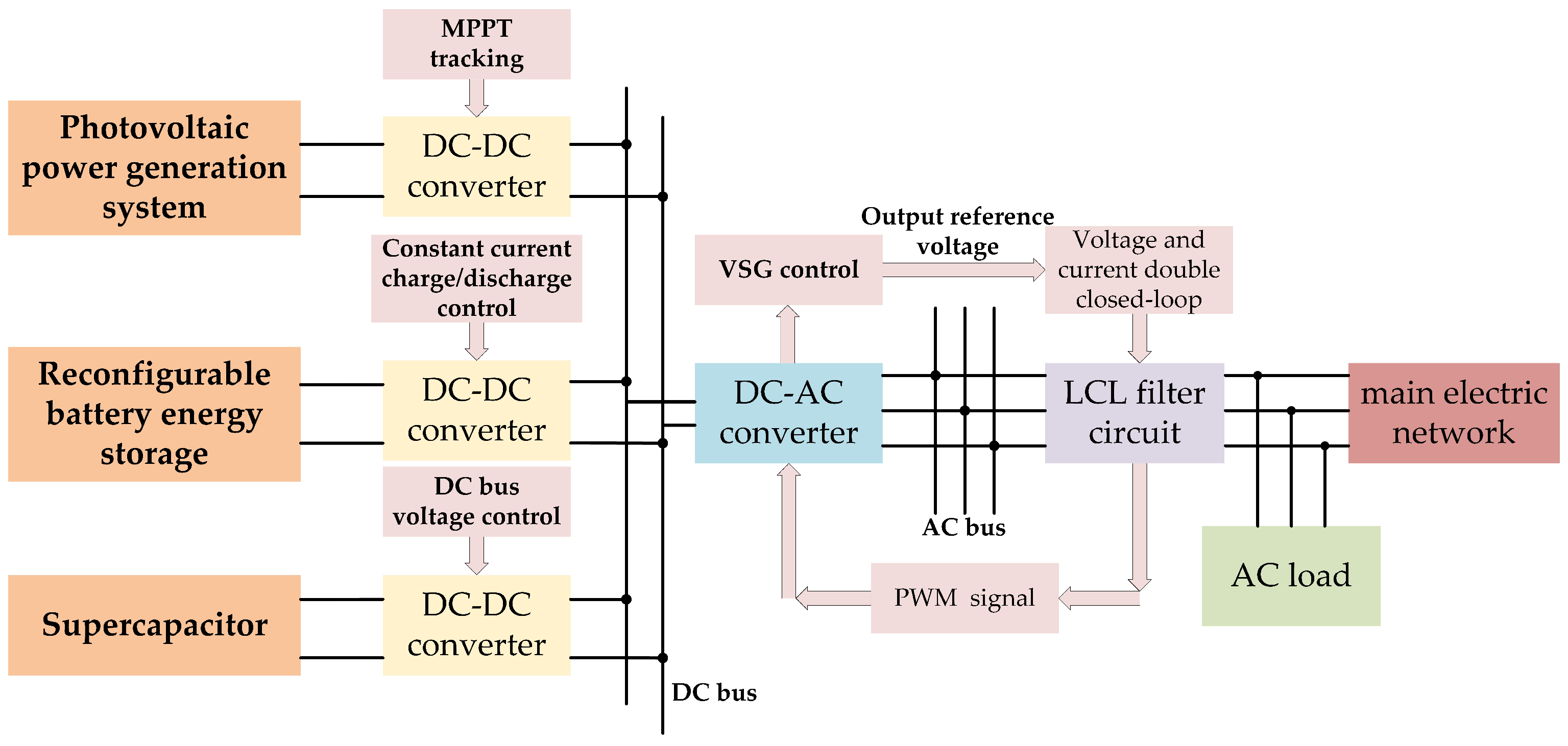
2.1. Microgrid Overall Structure

The reconfigurable microgrid system composed of new energy storage, photovoltaic power generation units, and supercapacitors is illustrated in Figure 1. Photovoltaic power generation systems, reconfigurable new energy storage, and supercapacitors are interfaced to a direct DC bus through a bidirectional DC/DC converter, and a DC/AC converter is used to connect the DC microgrid system to the AC network and supply power to the local load; the inverter unit is mainly composed of a three-phase inverter and LCL filter to realize grid-connected or islanding operation.

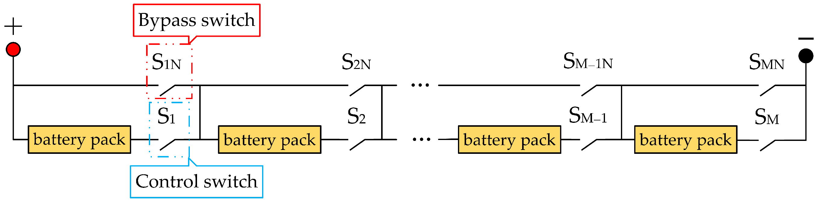
2.2. A New Reconfigurable Energy Storage System

To address the limitations of fixed series–parallel topology in traditional battery energy storage systems, a new reconfigurable battery network based on a switch-bypass architecture is adopted, and the network structure is schematically represented in Figure 2. The network consists of M battery packs connected in series, each of which is connected in series with a control switch Si and in parallel with a bypass switch SiN. During operation, the battery packs are controlled to be connected to or isolated from the charge–discharge network via the switches. The proposed strategy dynamically regulates the charging/discharging durations of individual battery units, effectively mitigating SOC disparities between modules while extending the cycle life of the energy storage system.
Additionally, upon detecting a faulty condition, the BMS executes a protective isolation protocol: deactivating the primary control circuit of the compromised energy storage unit while simultaneously enabling its redundant bypass pathway. This fault-tolerant topology ensures uninterrupted series connectivity for the operational battery modules within the energy storage array and effectively ensures the safety of the energy storage system without disrupting its normal operation [17].
When the reconfigurable battery is charged, the battery pack with the low SOC and good temperature state is connected to the charging network through the switch control; during discharge, the battery pack with high SOC and good temperature state is controlled to access the discharge network through the switch. From the above analysis, it can be seen that precise SOC monitoring for individual battery modules is crucial for enabling adaptive reconfiguration in energy storage systems. This study implements a dual-parameter characterization methodology, incorporating direct open-circuit voltage (OCV) measurements from individual energy storage modules with their corresponding electrochemical state mapping profiles (OCV-SOC characteristic curves). Subsequently, the state-of-charge (SOC) estimation undergoes precision enhancement through an extended Kalman filtering (EKF) algorithm [18], which implements recursive prediction–correction mechanisms to minimize electrochemical parameter estimation errors in the energy storage module.
The equivalent circuit model of the lithium battery is illustrated in Figure 3 [19], where U o c represents the open circuit voltage. U is the output voltage. R 0 is the internal resistance of the battery. R 1 and R 2 are the polarization resistance of the battery. C 1 and C 2 are the polarization capacitors of the battery.
The extended Kalman filtering (EKF) algorithm implementation for battery SOC estimation, depicted in Figure 4, initiates with mathematical model formulation through second-order RC network parameterization and coulombic integration principles. Subsequent computational stages involve nonlinear system linearization via Taylor series approximation, followed by recursive state variable prediction–correction cycles derived from Kalman filtering theory, ultimately yielding precise electrochemical state quantification for the energy storage module.

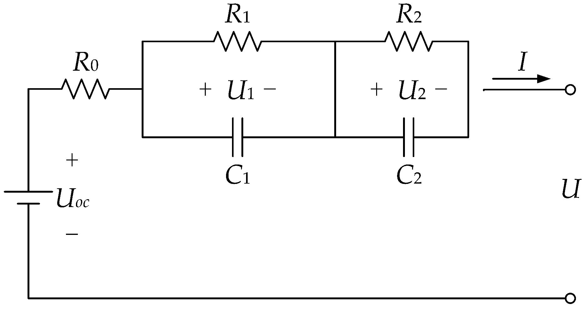
2.2.1. Establishment of State Equation and Output Equation of Lithium Battery Model

The system’s state-space formulation incorporates the battery’s SOC and dynamic polarization capacitance–voltage as state variables, with operational current profiles as inputs and terminal voltage measurements as observable outputs. The electrochemical state-space formulation is constructed through systematic integration of equivalent circuit network analysis and coulomb counting principles, as expressed in the following governing equations:
d S O C ( t ) / d t = I ( t ) / C N d U 1 ( t ) / d t = U 1 ( t ) / ( R 1 C 1 ) + I ( t ) / C 1 d U 2 ( t ) / d t = U 2 ( t ) / ( R 2 C 2 ) + I ( t ) / C 2
The output equation is:
U ( t ) = U o c ( t ) U 1 ( t ) U 2 ( t ) R 0 I ( t )
Discretization of Equations (1) and (2) yields the equation of state:
S O C ( k + 1 ) = S O C ( k ) I ( k ) Δ t / C N U 1 ( k + 1 ) = e Δ t / ( R 1 C 1 ) U 1 ( k ) + R 1 ( 1 e Δ t / ( R 1 C 1 ) ) I ( k ) U 2 ( k + 1 ) = e Δ t / ( R 2 C 2 ) U 2 ( k ) + R 2 ( 1 e Δ t / ( R 2 C 2 ) ) I ( k )
where S O C ( k ) is the SOC value of the battery at time k; I ( k ) is the charge–discharge current at time k; U 1 ( k ) is the voltage across the polarization capacitor C 1 at time k; U 2 ( k ) is the voltage across the polarization capacitor C 2 at time k; S O C ( k + 1 ) is the SOC value of the battery at time k + 1 ; U 1 ( k + 1 ) is the voltage across the polarization capacitor C 1 at time k + 1 ; U 2 ( k + 1 ) is the voltage across the polarization capacitor C 2 at time k + 1 ; C N is the actual capacity of the battery; Δ t is the sampling time interval.
The output equation is:
U ( k ) = U o c ( k ) U 1 ( k ) U 2 ( k ) R 0 I ( k )

2.2.2. Linearization

The EKF algorithm represents a nonlinear generalization of classical Kalman filtering theory. This study implements a first-order Taylor series approximation at system state estimation points, enabling the derivation of a discrete-time nonlinear state-space representation as follows:
x k + 1 = f ( x k , u k ) + w k y k = g ( x k , u k ) + v k
where x k is the state variable at time k; u k is the control input of the system; y k is the output value at time k; f ( x k , u k ) is the state transition function; g ( x k , u k ) is the measurement function; w k and v k are the process noise and measurement noise, respectively, both with zero mean values and uncorrelated with each other, denoted as w k N ( 0 , Q k ) and v k N ( 0 , R k ) ; Q k is the covariance matrix of the process noise; R k is the covariance matrix of the measurement noise.
The linearization process employs first-order Taylor series approximation centered at the system’s state estimation point, yielding the following mathematical representation:
f ( x k , u k ) f ( x ^ k , u k ) + f ( x k , u k ) x k | x k = x ^ k ( x k x ^ k ) g ( x k , u k ) g ( x ^ k , u k ) + g ( x k , u k ) x k | x k = x ^ k ( x k x ^ k )
Substitute Equation (6) into Equation (5) to obtain:
x k + 1 f ( x k , u k ) x k | x k = x ^ k x k + [ f ( x ^ k , u k ) A k x ^ k ] + w k y k g ( x k , u k ) x k | x k = x ^ k x k + [ g ( x ^ k , u k ) C k x ^ k ] + v k
From Equations (3) and (4), the state variable of the battery SOC estimation system is x k = S O C ( k ) , U 1 ( k ) , U 2 ( k ) T , and the system input is u k = I ( k ) . After linearizing the nonlinear equation through the first-order Taylor formula, the linearized matrix parameters are obtained as follows:
A k = f ( x k , u k ) x k | x k = x ^ k = 1 0 0 0 e Δ t Δ t ( R 1 C 1 ) ( R 1 C 1 ) 0 0 0 e Δ t Δ t ( R 2 C 2 ) ( R 2 C 2 )
B k = Δ t Δ t C N C N R 1 ( 1 e Δ t Δ t ( R 1 C 1 ) ( R 1 C 1 ) ) R 2 ( 1 e Δ t Δ t ( R 2 C 2 ) ( R 2 C 2 ) )
C k = g ( x k , u k ) x k | x k = x ^ k = U o c ( k ) S O C 1 1
D k = R 0

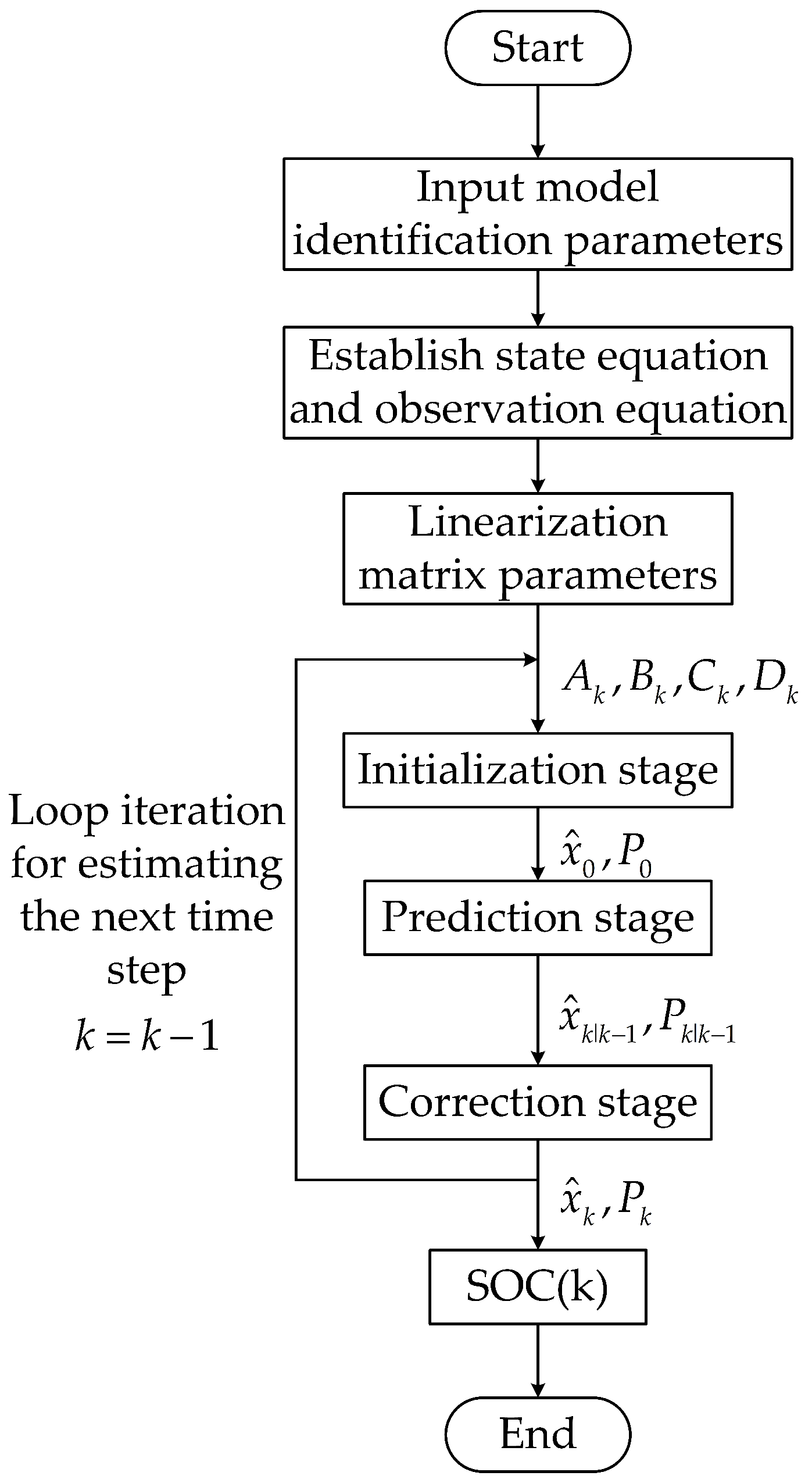
2.2.3. Initialize and Cycle Recursive Calculation

  • Initialization stage:
    x ^ 0 = E x 0 , P 0 = E x 0 x ^ 0 x 0 x ^ 0 T
  • Prediction stage:
    Predicted value of state variable:
    x ^ k | k 1 = f ( x ^ k 1 , u k 1 )
    The covariance matrix of state variable prediction error:
    P k | k 1 = A k 1 P k 1 A k 1 T + Q k 1
  • Correction stage:
    Gain matrix expression:
    K k = P k | k 1 C k T ( C k P k | k 1 C k T + R k ) 1
    State variable correction:
    x ^ k = x ^ k | k 1 + K k y k g ( x ^ k | k 1 , u k )
    The covariance matrix of state variable correction error:
    P k = ( I K k C k ) P k | k 1
  • Iteration Loop: Return to Step 2. to estimate the next time step.
where x ^ k 1 represents the optimal estimate of the state variable at time k 1 ; x ^ k | k 1 denotes the predicted value of the state variable at time k, derived from the optimal value of the state variable at time k 1 ; P k 1 is the error covariance of the state variable at time k 1 ; P k | k 1 represents the predicted value of the error covariance at time k, obtained from the error covariance at time k 1 ; y k is the true value of the observed variable of the system at time k; K k is the Kalman gain; and I is the identity matrix.

3. Control Strategy of Microgrid Unit Operation

As shown in Figure 5, the microgrid’s coordinated energy management framework primarily encompasses photovoltaic generation optimization through maximum power point tracking (MPPT) mechanisms [20], constant current charge/discharge control of reconfigurable battery energy storage [21], voltage stabilization control of a supercapacitor on DC bus, the control architecture incorporates VSG-based inverter regulation combined with dual-loop voltage–current control strategies for LCL filter networks [22,23]. This research focuses on developing advanced energy management strategies for reconfigurable battery systems, including optimized charge/discharge protocols and supercapacitor-based DC bus voltage stabilization control.

3.1. Charge and Discharge Control Strategy of Reconfigurable Battery

Traditional battery energy storage often compensates for photovoltaic power generation systems in two ways:
(1) Method 1: the energy storage system maintains constant output voltage characteristics while dynamically regulating its power setpoints to modulate charge/discharge current profiles, enabling effective photovoltaic generation power compensation [6,7].
(2) Method 2: the energy storage system ensures the stability of the DC bus voltage, and the supercapacitor’s output power is regulated to provide power compensation for the photovoltaic generation system [8].
In scenarios involving abrupt variations in photovoltaic generation or AC load power requirements, Method 1 induces frequent oscillations in the energy storage’s charging/discharging current, which substantially degrades the operational lifespan of the battery-based energy storage system. On the other hand, when the photovoltaic power generation or AC load demand power changes significantly, Method 2 requires an excessively high energy density of the supercapacitor, which may cause the SOC of the supercapacitor to reach the charge/discharge threshold in a short time. To address these issues, a charge and discharge control strategy for reconfigurable batteries was proposed to fully utilize their high energy density advantages. The DC–DC converter maintains steady current regulation during energy storage charging/discharging processes, whereas the reconfigurable battery energy storage dynamically adjusts the quantity of battery modules engaged in the charge/discharge circuit via switch-based mechanisms. This modulates the energy storage system’s output voltage level through active regulation, thereby changing its output power to compensate for components with large power difference amplitudes.
A reconfigurable battery energy storage system adjusts the output voltage through the series circuit and achieves constant current charge/discharge operation via the DC–DC converter [24,25]. The DC–DC conversion circuit structure is shown in Figure 6, where, V b a t is the output voltage of the reconfigurable battery energy storage system; L b a t is the energy storage inductance; I b a t is the discharge current of the reconfigurable battery energy storage; K1 and K2 are high-frequency power electronic switches; VD1 and VD2 are freewheeling diodes; C is the filter capacitor; V d c is the DC bus voltage.
PI control mode is adopted for energy storage constant current charge/discharge, and the control principle is illustrated in Figure 7. In the figure, I b a t * represents the expected discharge current, which is negative during charging and positive during discharging; NOT denotes the logical negation sign, indicating that the on–off state of switch K1 is opposite to that of switch K2.
The reconfigurable battery energy storage system requires dynamic determination of its battery cluster topology by power compensation requirements while ensuring the activated configuration’s output power complies with the prescribed operational constraint:
( 1 σ ) ( P o u t + P d c P p v ) P b a t ( 1 + σ ) ( P o u t + P d c P p v ) P b a t = V b a t I b a t
where P o u t is the output power of the inverter (load demand power); P d c is the power required to keep the DC bus voltage stable; P p v is the output power of the photovoltaic power generation system; P b a t is the output power of the reconfigurable battery energy storage; σ is the power compensation coefficient, generally not exceeding 0.2; V b a t is the terminal voltage of the reconfigurable battery energy storage.

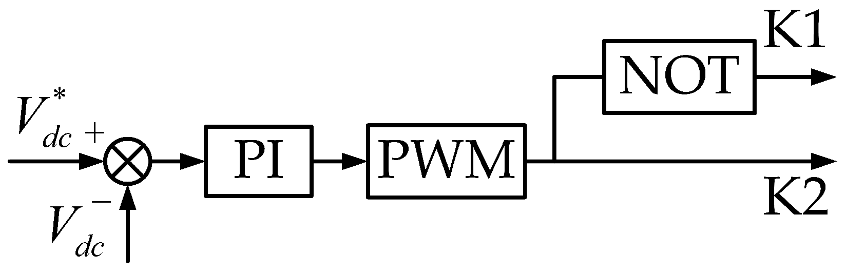
3.2. Control Strategy of Ultracapacitory

Supercapacitors have high power density and can be charged and discharged quickly in a short time. When the reconfigurable battery energy storage adjusts the output power dynamically by using the reconfiguration characteristic, the rapid switching of the high-frequency power electronic switch will produce a small power jump, and the high power characteristic of the supercapacitor can effectively compensate for the power jump caused by the reconfiguration process and at the same time can compensate for the small amplitude component of the power difference.
Furthermore, the supercapacitor regulates the DC bus voltage to a stable level via the DC–DC converter, thereby maintaining system stability. Constant voltage control adopts PI control mode, the control principle as shown in Figure 8. In the figure, V d c represents the DC bus voltage, V d c * denotes the reference DC bus voltage, and NOT stands for the logical negation symbol.

4. Microgrid Power Coordination Control Strategy

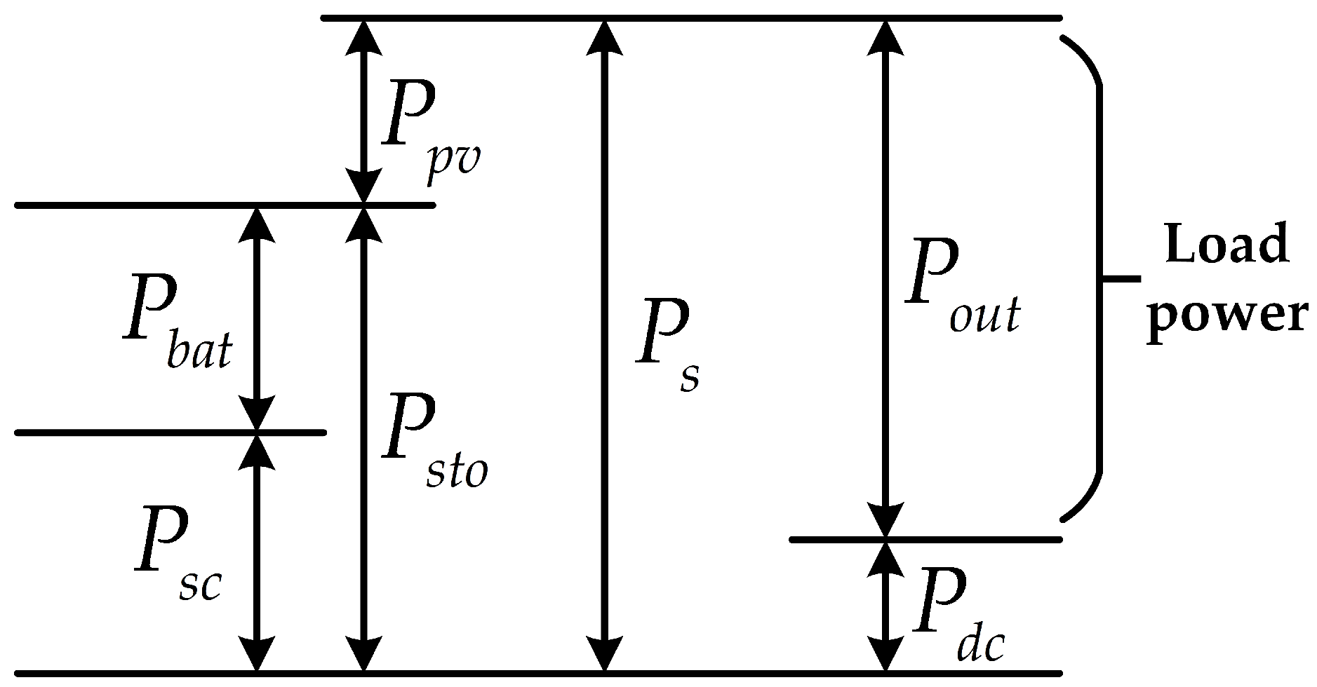
4.1. Energy Flow Relationship of the Microgrid System

Figure 9 illustrates the power flow distribution characteristics within the microgrid system’s integrated energy network.
The power between each unit shall satisfy the following relationship:
P b a t + P s c = P s t o P b a t = 1 / ( τ s + 1 ) P s t o P p v + P s t o = P s P o u t + P d c = P s
where P s is the sum of the power generation unit (including photovoltaic and hybrid energy storage); P o u t is the output power of the inverter (load power); P d c is the power required to keep the DC bus voltage stable; P p v is the output power of the photovoltaic power generation system; P s t o is the output power of the hybrid energy storage system; P b a t is the output power of the reconfigurable battery energy storage system; P s c is the output power of the supercapacitor; s is the differential element; 1 1 ( τ s + 1 ) ( τ s + 1 ) is the low-pass filter element; τ is the time constant.

4.2. Coordinated Power Control of Microgrid

For optimal solar energy harvesting, the photovoltaic system maintains MPPT operation. Through real-time comparison of photovoltaic generation output and load demand, integrated with hybrid energy storage charge–discharge dynamics, the system operates in two distinct operational regimes:
Mode 1: under conditions where photovoltaic output falls below load demand, the reconfigurable battery storage system and ultracapacitors provide coordinated power compensation to address the energy shortfall.
Mode 2: during periods of photovoltaic surplus generation, the system simultaneously fulfills load requirements and directs excess energy to either the reconfigurable battery storage or supercapacitor for energy buffering.
The hybrid energy storage system demonstrates significant performance complementarity between battery and supercapacitor technologies. During photovoltaic power compensation, the supercapacitor’s high power density and extended cycle life make it ideal for mitigating high-frequency, low-amplitude fluctuations, while the battery’s high energy density enables effective compensation for low-frequency, high-amplitude power variations.
Based on the above analysis, the reconfigurable battery storage selects the appropriate battery pack for constant current charge/discharge according to the power difference, compensating for the larger power amplitude component. Meanwhile, the supercapacitor utilizes its high power density characteristic to compensate for the power fluctuations caused by the battery pack reconfiguration process. The specific working logic of the microgrid system is shown in Figure 10.

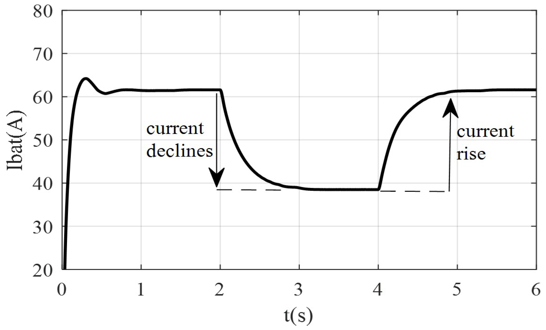
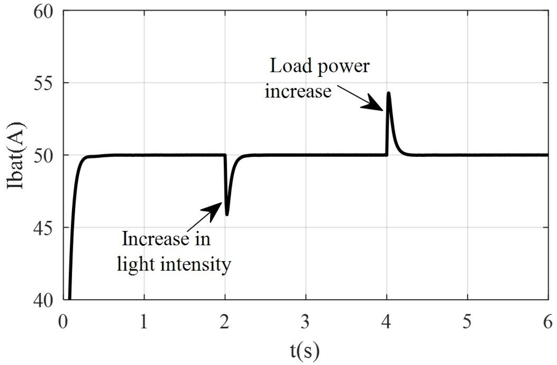
5. Simulated Analysis

The proposed control strategy’s efficacy is validated through a MATLAB/Simulink-based simulation platform, where performance is benchmarked against conventional battery-only microgrid control architectures. In defining simulation scenarios, multiple operational parameters influence microgrid mode transitions, with two principal disturbance sources identified: photovoltaic output variability and load power dynamics. Given the predominant influence of irradiance levels on photovoltaic output, photovoltaic variability is emulated through controlled irradiance modulation. The reconfigurable storage system is implemented using a four-module battery configuration, with key system parameters detailed in Table 1.
Condition 1: The photovoltaic generation initially operates below load demand levels, with irradiance set at 700 W/m2 and AC load at 150 kW. At t = 2 s, irradiance experiences a step increase to 900 W/m2, followed by a load demand surge to 175 kW at t = 4 s.
During the operation of the microgrid, the discharge current waveforms of traditional battery energy storage and reconfigurable battery energy storage are illustrated in Figure 11 and Figure 12, respectively. The output voltage waveform of the reconfigurable battery energy storage is illustrated in Figure 13, while the DC bus voltage waveform is illustrated in Figure 14. When traditional battery energy storage is used, the output power of each unit in the microgrid system is illustrated in Figure 15. In contrast, when reconfigurable battery energy storage is adopted, the output power of each unit is illustrated in Figure 16. The SOC value of each battery pack in the energy storage changes with time as illustrated in Table 2.
From Figure 11, the observations confirm that when the photovoltaic power generation increases at 2 s while the load demand power remains unchanged, the discharge current of the traditional battery energy storage decreases from 61.6 A to 38.5 A. Similarly, when the photovoltaic power generation remains unchanged at 4 s and the load demand power increases, the discharge current of the traditional battery energy storage decreases from 61.6 A to 38.5 A. This indicates that the current of the traditional battery energy storage fluctuates significantly during the entire operation process, which will severely reduce the battery lifespan. From Figure 12, it can be seen that the discharge current of the reconfigurable battery energy storage remains positive and stable at 50 A, indicating that the reconfigurable battery energy storage system operates in a constant current discharge state. This effectively addresses the issue of battery lifespan degradation caused by continuously varying charge/discharge currents when traditional energy storage compensates for photovoltaic power.
Figure 13 and Table 2 demonstrate that during 0∼2 s, reconfigurable battery energy storage controls battery packs 1, 2, and 3 with larger SOC to discharge together, and the series output voltage is about 1540 V; during 2∼4 s, due to the increase in illumination intensity, photovoltaic power generation power increases, energy storage controls battery packs 1 and 2 to discharge together through switches, and the output voltage decreases from 1540 V to 1038 V; during 4∼6 s, because the AC load demand power increases to 175 kW, the energy storage system continues to reconfigure at 4 s, and the output voltage increases from 1038 V to 1540 V by controlling battery packs 1, 2, and 3 to discharge together through switches.
Figure 14 demonstrates that the DC bus voltage is stable at 1500 V. At 2 s and 4 s because the energy storage system begins to reconstruct, small voltage fluctuation will occur at this time, and stability can be restored in a short time, indicating that the DC bus voltage stabilization effect of the supercapacitor is good. that the DC bus voltage is stable at 1500 V. At 2 s and 4 s, because the energy storage system begins to reconstruct, a small voltage fluctuation will occur at this time, and stability can be restored in a short time, indicating that the DC bus voltage stabilization effect of the supercapacitor is good.
By comparing Figure 15 and Figure 16, the observations confirm that the output power of the microgrid system under both control strategies stabilizes at 150 kW and 175 kW, meeting the load power demand. However, the dynamic response stabilization time for the traditional battery energy storage control strategy is approximately 1.25 s, whereas for the reconfigurable battery energy storage control strategy, it is about 0.2 s. This indicates that the dynamic performance of the reconfigurable battery energy storage control strategy is superior to that of the traditional control strategy. It can be seen from Figure 16 that in the whole simulation stage, the output power of each unit in the microgrid is conserved, i.e., P p v + P b a t + P s c = P o u t + P d c , wherein the reconfigurable battery energy storage compensates for the component with larger amplitude of the power difference (the difference between the load demand power and the photovoltaic power generation power, i.e., P o u t + P d c P p v ), and the supercapacitor compensates for the component with smaller amplitude of the power difference and simultaneously compensates for the power mutation caused by the battery reconfiguration process by using the high power density characteristic.
Condition 2: The PV output power is greater than the load demand power. The initial light intensity and initial AC load are set to 1700 Lux and 150 kW, respectively. At 2 s, the light intensity suddenly decreases to 1600 Lux, and at 4 s, the load power demand increases to 175 kW.
During the operation of the microgrid, the output current waveforms of traditional battery energy storage and reconfigurable battery energy storage are shown in Figure 17 and Figure 18, respectively. The output voltage waveform of the reconfigurable battery energy storage is shown in Figure 19, while the DC bus voltage waveform is shown in Figure 20. When traditional battery energy storage is used, the output power of each unit in the microgrid system is shown in Figure 21. In contrast, when reconfigurable battery energy storage is adopted, the output power of each unit is shown in Figure 22. The SOC value of each battery pack in the energy storage changes with time as shown in Table 3.
From Figure 17, the observations confirm that when the photovoltaic power is reduced at 2 s while the load demand power remains unchanged, the charging current of the traditional battery energy storage decreases from 38.5 A to 23.1 A. Similarly, when the photovoltaic power remains unchanged at 4 s and the load demand power increases, the discharge current of the traditional battery energy storage decreases from 23.1 A to 0 A. This indicates that the current of the traditional battery energy storage fluctuates significantly during the entire operation process, which will severely reduce the battery lifespan. From Figure 18, it can be seen that the discharge current of the reconfigurable battery energy storage remains negative and stable at 50 A, indicating that the reconfigurable battery energy storage system operates in a constant current charging state. This effectively addresses the issue of battery lifespan degradation caused by continuously varying charge/discharge currents when traditional energy storage compensates for photovoltaic power.
Figure 19 and Table 3 demonstrate that during 0∼2 s, in addition to supplying power to AC loads, the excess electric quantity of the photovoltaic power generation system is transferred to battery packs 3 and 4 with smaller SOC, and the series output voltage is about 1100 V; during 2∼4 s, due to the decrease in illumination intensity, the photovoltaic power generation power decreases, and at 2 s, the energy storage begins to reconstruct, and the excess electric quantity of the photovoltaic power generation system is transferred to battery pack 4 with the smallest SOC, and the output voltage decreases from 1100 V to 550 V; during 4∼6 s, because the AC load demand power increases to 175 kW, at this time, the photovoltaic power generation power is slightly greater than the load demand power, the excess electricity maintains the DC bus voltage stable, the reconfigurable energy storage ends its work at this stage, and the output voltage decreases from 550 V to 0 V.
Figure 20 demonstrates that the DC bus voltage is stable at 1500 V. At 2 s and 4 s, because the energy storage system begins to reconstruct, a small voltage fluctuation will occur at this time, and stability can be restored in a short time, indicating that the DC bus voltage stabilization effect of the supercapacitor is good.
By comparing Figure 21 and Figure 22, the observations confirm that the output power of the microgrid system under both control strategies stabilizes at 150 kW and 175 kW, meeting the load power demand. However, the dynamic response stabilization time for the traditional battery energy storage control strategy is approximately 1.25 s, whereas for the reconfigurable battery energy storage control strategy, it is about 0.2 s. The reconfigurable battery energy storage control strategy demonstrates enhanced dynamic performance characteristics compared to conventional control approaches.
Figure 22 demonstrates that the output power of the microgrid system is stable at 150 kW and 175 kW, which can meet the load power demand; in the whole simulation stage, the output power of each unit in the microgrid is conserved, i.e., P p v + P b a t + P s c = P o u t + P d c , wherein the reconfigurable battery stores energy to compensate for the component with larger amplitude of the power difference (the difference between the photovoltaic power generation power and the load demand power, i.e., P p v P o u t P d c ), and the super capacitor compensates for the component with smaller amplitude of the power difference and simultaneously compensates for the power mutation caused by the battery reconfiguration process by using the high power density characteristic.
In summary, reconfigurable battery energy storage achieves constant current charge/discharge, thereby improving the cycle life of the energy storage system. Additionally, the control strategy proposed in this paper fully utilizes the complementary characteristics of reconfigurable battery storage and supercapacitors. Specifically, reconfigurable battery storage compensates for components with large power difference amplitudes through its dynamic reconfiguration and high energy density characteristics, while supercapacitors compensate for components with small power difference amplitudes and power fluctuations caused by reconfiguration through their high power density characteristics.

6. Conclusions

Aiming to address the security and limitations of traditional energy storage in microgrids, a new reconfigurable energy storage microgrid structure is designed, and a novel power coordination control strategy for reconfigurable energy storage microgrids is proposed. The proposed strategy’s efficacy is validated via MATLAB/Simulink-based simulation studies, with results indicating the following key findings:
  • In this paper, traditional energy storage is replaced with reconfigurable battery energy storage, and the reliability and stability of the microgrid system are enhanced by leveraging the structural advantages of the reconfigurable network.
  • During the operation of the microgrid, the charge/discharge control strategy proposed in this paper enables constant current charge/discharge of the energy storage system and extends the service life of the battery.
  • The control strategy proposed in this paper fully utilizes the complementary characteristics of reconfigurable battery energy storage and supercapacitors. It can effectively and rapidly adjust the system power output, suppress power fluctuations caused by variations in photovoltaic power generation and load mutations in the microgrid system, and improve the quality of the system’s output power.
  • The research results of this paper provide theoretical support for the new energy storage compensation in photovoltaic power generation. This approach can also be applied to other renewable energy generation systems, such as wind power and tidal power. In the future, large-scale experiments or practical applications can be conducted to verify the feasibility of this energy storage compensation method in actual power grid environments.

Author Contributions

All the authors contributed to the research in this paper. Conceptualization, X.L. and L.J.; data curation, T.Z. and Z.Z.; formal analysis, X.L. and T.Z.; investigation, X.L. and L.J.; methodology, X.L. and L.J.; resources, T.Z.; software, X.L. and Z.Z.; supervision, X.L., L.J. and T.Z.; validation, X.L. and T.Z.; visualization, X.L.; writing—original draft, X.L.; and writing—review and editing, X.L. and L.J. All authors have read and agreed to the published version of the manuscript.

Funding

This research received no external funding.

Data Availability Statement

Data Availability Statement: The original contributions of this study are included in this article; further inquiries can be directed to the corresponding author.

Conflicts of Interest

Author Libo Jiang was employed by Sichuan Energy Internet Research Institute, Tsinghua University. The remaining authors declare that this research was conducted in the absence of any commercial or financial relationships that could be construed as potential conflicts of interest.

References

  1. Li, B.; Chen, M.; Zhong, H.; Ma, Z.; Liu, D.; He, G. Summary of long-term planning for high-proportion renewable energy new power systems. Proc. CSEE 2023, 43, 555–581. [Google Scholar]
  2. Shamarova, N.; Suslov, K.; Ilyushin, P.; Shushpanov, I. Review of Battery Energy Storage Systems Modeling in Microgrids with Renewables Considering Battery Degradation. Energies 2022, 15, 6967. [Google Scholar] [CrossRef]
  3. Yang, F.; Ren, Y.; Yun, P.; Xue, Y.; Lian, M.; Xu, W. Coordinated Control and Power Distribution of Hybrid Energy Storage System of Twostage Lithium Batteries and Supercapacitors. Renew. Energy Sources 2019, 37, 361–366. [Google Scholar]
  4. Arunkumar, C.R.; Manthati, U.B.; Srinivas, P. Accurate Modelling and Analysis of Battery–supercapacitor Hybrid Energy Storage System in DC Microgrid Systems. Energy Syst. 2021, 13, 1–19. [Google Scholar] [CrossRef]
  5. Hai, T.; Fan, P.; Wang, J.; Lin, G. Photovoltaic Application Based on Hybrid Energy Storage of Super Capacitor and Battery. Renew. Energy Sources 2024, 42, 1219–1225. [Google Scholar]
  6. Leng, D.; Polmai, S. Virtual Synchronous Generator Based on Hybrid Energy Storage System for PV Power Fluctuation Mitigation. Appl. Sci. 2019, 9, 5099. [Google Scholar] [CrossRef]
  7. Yang, P.; Chen, Z.; Luo, T.; Zhu, J.; Liu, B.; Chen, X. Control method of photovoltaic power generation and hybrid energy storage based on VSG. Power Syst. Clean Energy 2023, 39, 83–91+113. [Google Scholar]
  8. Zhang, C.; Dong, J.; Liu, J.; Ben, B. Control strategy of hybrid energy storage system based on batteries and supercapacitors. Trans. China Electrotech. Soc. 2014, 29, 334–340. [Google Scholar]
  9. Dang, J.; Xiao, D.; Zhang, X.; Jia, R.; Jiao, Y. Optimal configuration of retired battery reconfigurable network considering switching losses. J. Energy Storage 2024, 101, 113735. [Google Scholar] [CrossRef]
  10. Muhammad, S.; Rafique, M.U.; Li, S.; Shao, Z.; Wang, Q.; Liu, X. Reconfigurable Battery Systems: A Survey on Hardware Architecture and Research Challenges. ACM Trans. Des. Autom. Electron. Syst. 2019, 24, 1–27. [Google Scholar] [CrossRef]
  11. Bajaj, A.; Li, W.; Xiong, M.; Mou, J.; Garg, A.; Gao, L.; Bose, B. A Novel Self-Reconfigurable Battery Pack Design with and without Active Cell Balancing. Energy Technol. 2024, 12, 2401055. [Google Scholar] [CrossRef]
  12. Wan, G.; Zhang, Q.; Zhang, W.; Li, J.; Li, M.; Li, S.; Fu, Z.; Liu, J. Research on topology technology of integrated battery energy storage system with reconfigurable battery and converter. J. Energy Storage 2023, 96, 112688. [Google Scholar] [CrossRef]
  13. Momayyezan, M.; Hredzak, B.; Agelidis, V.G. A Load-Sharing Strategy for the State of Charge Balancing Between the Battery Modules of Integrated Reconfigurable Converter. IEEE Trans. Power Electron. 2017, 32, 4056–4063. [Google Scholar] [CrossRef]
  14. Guo, J.; Wang, X.; Sun, C. Balanced Charging Method of Power Batteries with Reconstructed Series-Parallel Structure. Electr. Power Autom. Equip. 2019, 39, 163–168. [Google Scholar]
  15. Momayyezan, M.; Abeywardana, D.B.; Hredzak, B.; Agelidis, V.G. Integrated Reconfigurable Configuration for Battery/Ultracapacitor Hybrid Energy Storage Systems. IEEE Trans. Energy Convers. 2016, 31, 1583–1590. [Google Scholar] [CrossRef]
  16. Zhang, C.; Shi, M.; Xu, C.; Huang, Z.; Ci, S. Intrinsic Safety Mechanism and Example Analysis of Energy Storage System Based on Dynamic Reconfigurable Battery Network. Energy Storage Sci. Technol. 2022, 11, 2442–2451. [Google Scholar]
  17. Ci, S.; Zhang, C.; Liu, B.; Zhou, Y. Dynamic Reconfigurable Battery Energy Storage Technology: Principle and Application. Energy Storage Sci. Technol. 2023, 12, 3445–3455. [Google Scholar]
  18. Liu, X.; Jiang, L.; Gao, S.; Zheng, T.; Guo, Y. SOC Equalization Strategy of Reconfigurable Energy Storage System Based on Active Equalization Technology. J. Electr. Eng. 2025, 1–10. Available online: http://kns.cnki.net/kcms/detail/10.1289.TM.20241115.1058.002.html (accessed on 15 January 2025).
  19. Ju, Y.J.; Lin, S.Q.; Gang, L. Simulation of Second-Order RC Equivalent Circuit Model of Lithium Battery Based on Variable Resistance and Capacitance. J. Cent. South Univ. 2020, 27, 2606–2613. [Google Scholar]
  20. Nie, X.; Lai, J. Review of Global MPP Tracking Control Methods for PV Arrays in Partial Shadow. Grid Technol. 2014, 38, 3279–3285. [Google Scholar]
  21. Peng, S.; Cao, Y.; Cai, X. Access Mode and Control Strategy of Large Battery Energy Storage System to Microgrid. Autom. Electr. Power Syst. 2011, 35, 38–43. [Google Scholar]
  22. Zheng, T.W.; Chen, L.J.; Chen, T.Y.; Mei, S.W. Technology and Prospect of Virtual Synchronous Generator. Autom. Electr. Power Syst. 2015, 39, 165–175. [Google Scholar]
  23. Lü, Z.; Sheng, W.; Zhong, Q.; Liu, H.; Zeng, Z.; Yang, L.; Liu, L. Virtual Synchronous Generator and its Application in Microgrid. Proc. CSEE 2014, 34, 2591–2603. [Google Scholar]
  24. Lei, Z.; Wang, F.; Gao, Y.; Ruan, Y. Research Status and Application Analysis of Bidirectional DC-DC Converter for DC Microgrid. Trans. China Electrotech. Soc. 2016, 31, 137–147. [Google Scholar]
  25. Banguero, E.; Correcher, A.; Pérez-Navarro, Á.; Morant, F.; Aristizabal, A. A Review on Battery Charging and Discharging Control Strategies: Application to Renewable Energy Systems. Energies 2018, 11, 1021. [Google Scholar] [CrossRef]
Figure 1. Microgrid system overall structure diagram.
Energies 18 01040 g001
Figure 2. A novel reconfigurable battery network based on switch bypass.
Energies 18 01040 g002
Figure 3. Equivalent circuit model of lithium battery.
Energies 18 01040 g003
Figure 4. Flow chart of SOC estimation by EKF method.
Energies 18 01040 g004
Figure 5. Control architecture for collaborative operation of units.
Energies 18 01040 g005
Figure 6. DC–DC converter circuit structure.
Energies 18 01040 g006
Figure 7. Principle block diagram of constant current charge/discharge control.
Energies 18 01040 g007
Figure 8. Principle block diagram of constant voltage control.
Energies 18 01040 g008
Figure 9. Microgrid power flow diagram.
Energies 18 01040 g009
Figure 10. Microgrid system working logic diagram.
Energies 18 01040 g010
Figure 11. Simulation waveform of the discharge current of the traditional battery energy storage.
Energies 18 01040 g011
Figure 12. Simulation waveform of the discharge current of the reconfigurable battery.
Energies 18 01040 g012
Figure 13. Simulation waveform of reconfigurable battery energy storage output voltage.
Energies 18 01040 g013
Figure 14. DC bus voltage simulation waveform.
Energies 18 01040 g014
Figure 15. Simulation waveform of the output power for each unit in the microgrid when using traditional battery energy storage.
Energies 18 01040 g015
Figure 16. Simulation waveform of the output power for each unit in the microgrid when using reconfigurable battery energy storage.
Energies 18 01040 g016
Figure 17. Simulation waveform of the charge current of the traditional battery energy storage.
Energies 18 01040 g017
Figure 18. Simulation waveform of the charge current of the reconfigurable battery.
Energies 18 01040 g018
Figure 19. Simulation waveform of reconfigurable battery energy storage output voltage.
Energies 18 01040 g019
Figure 20. DC bus voltage simulation waveform.
Energies 18 01040 g020
Figure 21. Simulation waveform of the output power for each unit in the microgrid when using traditional battery energy storage.
Energies 18 01040 g021
Figure 22. Simulation waveform of the output power for each unit in the microgrid when using reconfigurable battery energy storage.
Energies 18 01040 g022
Table 1. Simulation model parameter setting.
ParameterNumerical Value
Initial SOC value of battery pack 1: SOC170%
Initial SOC value of battery pack 2: SOC268%
Initial SOC value of battery pack 3: SOC370%
Initial SOC value of battery pack 4: SOC470%
Terminal voltage of each battery pack/V434.73∼581.99 (SOC 5∼95%)
The capacity of each battery pack/Ah20
Reference DC bus voltage/V1500
The absolute value of constant current charge/discharge current/A50
Initial AC load/kW150
Simulation time/s6
Table 2. The SOC of each battery pack varies with simulation time.
Battery’s SOC0 s2 s4 s6 s
SOC170%69.86%69.72%69.58%
SOC268%67.86%67.72%67.58%
SOC366%65.86%65.86%65.72%
SOC464%64%64%64%
Table 3. The SOC of each battery pack varies with simulation time.
Battery’s SOC0 s2 s4 s6 s
SOC170%70%70%70%
SOC268%68%68%68%
SOC366%66.14%66.14%66.14%
SOC464%64.14%64.28%64.28%
Disclaimer/Publisher’s Note: The statements, opinions and data contained in all publications are solely those of the individual author(s) and contributor(s) and not of MDPI and/or the editor(s). MDPI and/or the editor(s) disclaim responsibility for any injury to people or property resulting from any ideas, methods, instructions or products referred to in the content.

