Article

Comparative Study of Voltage and Control Characteristics of Two-Core and Single-Core Step-Up/Down Thyristor-Controlled Phase-Shifting Transformers

1
State Grid Jiangsu Electric Power Co., Ltd., Research Institute, Nanjing 211103, China
2
School of Electrical Engineering, Southeast University, Nanjing 210096, China
*
Author to whom correspondence should be addressed.
Energies 2025, 18(4), 837; https://doi.org/10.3390/en18040837
Submission received: 22 November 2024 / Revised: 8 January 2025 / Accepted: 7 February 2025 / Published: 11 February 2025
(This article belongs to the Section F: Electrical Engineering)

Abstract

:
The thyristor-controlled phase-shift transformer (TCPST) is an effective means of controlling power flow, exhibiting a simple structure and a long operating life. However, conventional TCPSTs are limited in their ability to regulate the phase-shifting angle, necessitating the matching of the step-up/down transformer to control the amplitude of voltages. Therefore, this paper puts forth two distinct structures of TCPSTs, each of which is capable of regulating both the phase-shifting angle and the amplitude of voltages: the two-core step-up/down thyristor-controlled phase-shifting transformer (TCSUD-TCPST) and the single-core step-up/down thyristor-controlled phase-shifting transformer (SCSUD-TCPST). Moreover, a comparison was conducted between the topology structure and the thyristor-controlled strategies of the TCSUD-TCPST and the SCSUD-TCPST. The coupling relationship and the limitations of the phase-shifting angle and the amplitude of voltages are illustrated, indicating that the SCSUD-TCPST appears to be a more suitable option for power transmission. Furthermore, the considerable static and dynamic characteristics of the TCSUD-TCPST and the SCSUD-TCPST were investigated through the PLECS simulation platform, which was also employed to further verify the aforementioned conclusions.

1. Introduction

Flexible alternative current transmission systems (FACTS) represent an effective means of balancing the power flow distribution of transmission lines, enhancing the ability of the distribution system to accept a more significant scale of renewable energy and enabling flexible operation and rapid control of power grids [1,2,3]. Among the various FACTS devices, the phase-shifting transformer (PST) and the unified power flow controller (UPFC) have been the subject of extensive study due to their regulatory performance and the advantages they offer in terms of power and power grid voltage regulation [4,5].
As one of the most powerful FACTS devices, the UPFC is capable of addressing the majority of issues related to power flow control, reactive power compensation, and system oscillation suppression within a power system [4,6]. However, the operating and maintenance costs of the UPFC are very high. In comparison, PSTs have a lower installed cost, with the cost of PSTs only being one-tenth to one-fifth of that of UPFCs. Therefore, PSTs with lower investment and operation and maintenance costs have broader application prospects in practical projects.
PSTs can be broadly classified into two main categories: the mechanical phase-shifting transformer (MPST) and the thyristor-controlled phase-shifting transformer (TCPST). As shown in Figure 1, the conventional MPST employs a mechanical tap structure to regulate the secondary voltage of transformers, while the TCPST regulates the secondary voltage of transformers by controlling the on and off states of thyristor groups. The majority of phase shifters installed in the project are still MPSTs. The first MPST was installed in the United States in 1938 [7]. Subsequently, numerous European countries have installed MPST to regulate power flow [8,9,10]. The utilization of mechanical switches imposes constraints on the adjustment speed, capacity, resilience, and lifespan of mechanical phase shifters, limiting their applications to steady-state adjustments. In contrast, TCPSTs not only overcome these limitations but also facilitate transient adjustments [4,11]. The controllable phase shifter with a dual-core symmetrical structure, also referred to as the two-core symmetrical discrete thyristor-controlled phase-shifting transformer (TCSD-TCPST), exhibits a considerable adjustment range, making it the subject of extensive research and deployment.
Nevertheless, the present focus of research into TCPSTs is mainly on power flow control optimization, control strategy improvement, system transient stability, and parameter design [12,13,14]. There is a paucity of research in the topological design of TCPSTs. The conventional TCSD-TCPST is only capable of modifying the phase angle of the voltage, necessitating the involvement of a step-up/down transformer to alter the amplitude of the voltage. The independent fast thyristor-controlled phase-shifting transformer (IF-TCPST) was proposed to simplify the structure and to independently adjust voltage amplitude [15]. However, the range of the voltage amplitude and phase-shifting angle of IF-TCPST are still limited. The combination of the step-up/down transformer and the TCSD-TCPST allows for the modification of the voltage amplitude and phase angle separately in a two-core step-up/down thyristor-controlled phase-shifting transformer (TCSUD-TCPST) composed of the series transformer (ST) and the excitation transformer (ET). This proposed approach offers the benefits of saving floor space and reducing investment costs without the separate step-up/down transformer, while the ratio of ST is affected by the grid line parameters. By merging the ST into the part of the ET, the single-core step-up/down thyristor-controlled phase-shifting transformer (SCSUD-TCPST) allows for the modification of the voltage amplitude and phase angle separately using a simpler single-core structure, and its ratio is not affected by the grid line parameters.
In this study, a comparison was conducted between the topology structure and the thyristor-controlled strategies of the TCSUD-TCPST and the SCSUD-TCPST. The coupling relationship and the limitations of the phase-shifting angle and the amplitude of voltages are illustrated, indicating that the SCSUD-TCPST appears to be a more suitable option for power transmission. Furthermore, the considerable static and dynamic characteristics of the TCSUD-TCPST and the SCSUD-TCPST were investigated through the PLECS simulation platform, which was also employed to further verify the aforementioned conclusions.

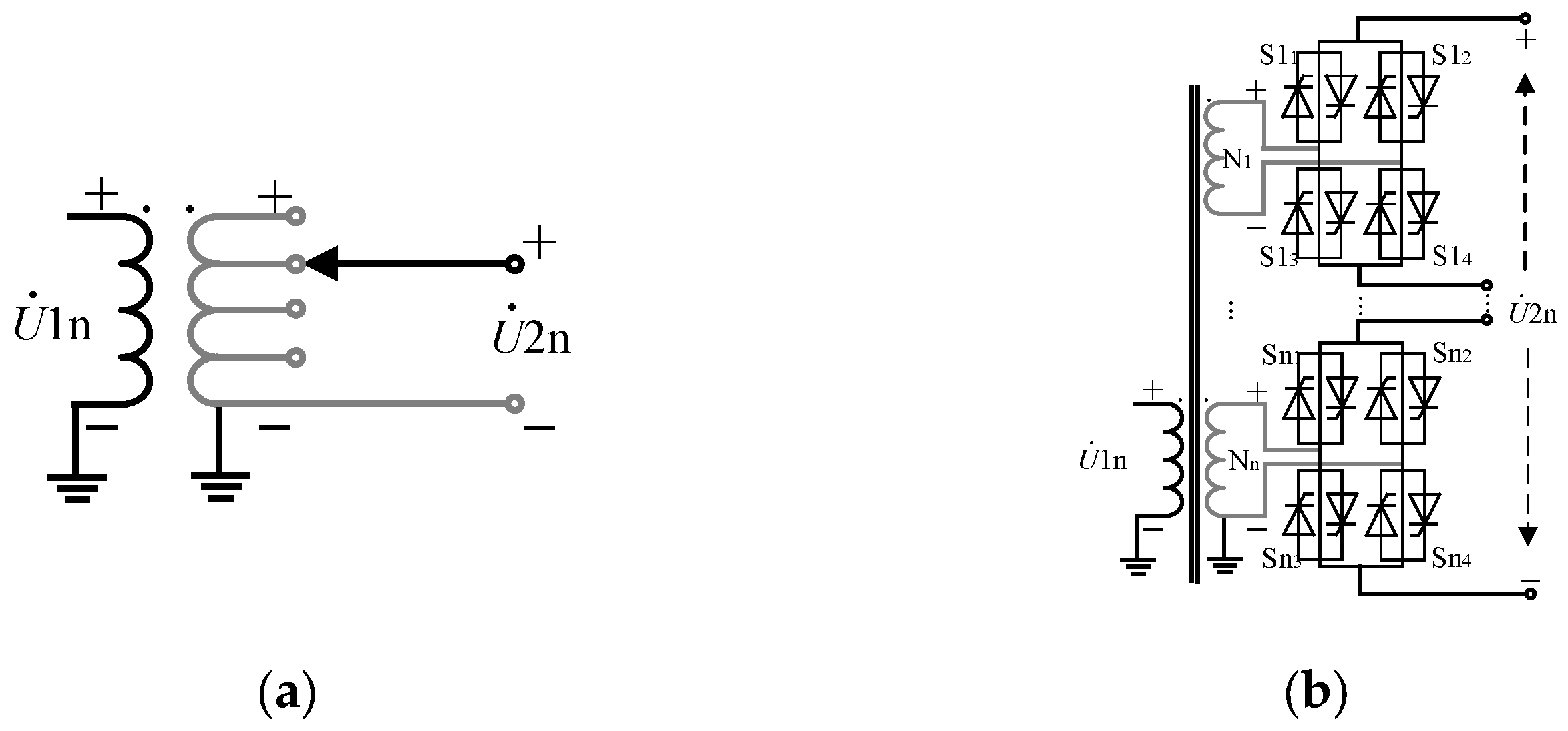
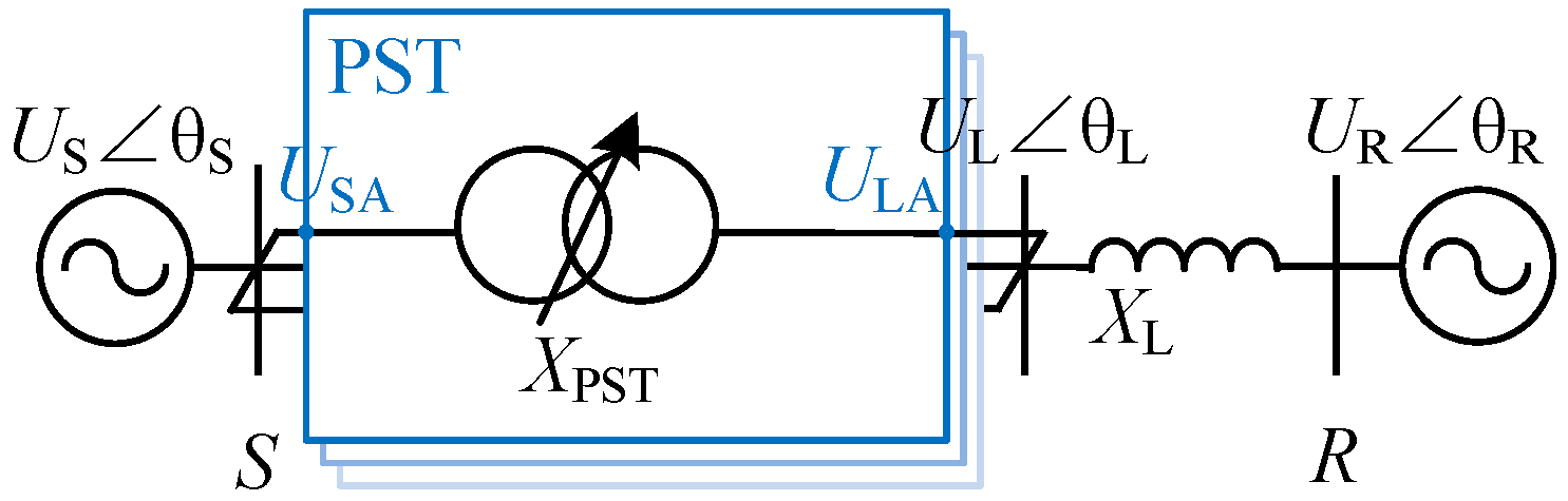
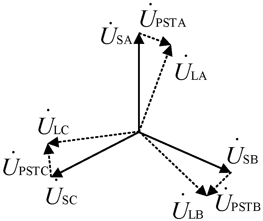
2. Basic Principle of TCPST

The equivalent schematic diagram of a transmission line after installing a TCPST is shown in Figure 2. US and UR are the sending and receiving voltages, respectively; UL is the voltage after phase shifting. Xpst is the reactance of the TCPST, and XL is the equivalent reactance of the line. The sending voltage source US transfers active power through TCPST, and the specific transmission active power value can be derived as Equation (1). As shown in Figure 3 and Equation (1), the TCPST modifies its voltage taken up in the transmission line by altering the impedance value of the XPST, thereby modifying the amplitude and the phase of the output voltage UL of the TCPST as well as the value of the active power transmitted to the receiving voltage source UR.
P = U L U R X L + X PST sin ( θ L θ R )
Given the relatively abstract nature of the impedance value of the XPST, it is the range of the amplitude and phase of the output voltage UL of the TCPST that provide a more direct reflection of the TCPST’s ability. Furthermore, as TCPSTs are typically installed in three phases separately, they can be adjusted in each phase to transmit constant active power in a three-phase asymmetrical grid. However, the grid in which TCPSTs are installed is typically three-phase symmetrical. Therefore, this paper examines the range of the amplitude and phase of the output voltage in phase A ULA to assess the capability of TCPSTs for simplified representation.

3. Voltage Step-Down and Phase-Shifting Capability Calculations of the TCSUD-TCPST

3.1. Topology Structure of TCSUD-TCPST

As shown in Figure 4, the topology structure of the TCSUD-TCPST is analogous to that of the TCSD-TCPST, comprising an ST and an ET. The sole distinction is that the ratios of the ST of the TCSUD-TCPST ns1 and ns2 are not necessarily equal, which is not permitted for the “symmetrical” TCSD-TCPST. The following subsections demonstrate the impact of the unequal values of ns1 and ns2.

3.2. Calculation of the Phase-Shifting Angle

To facilitate the analysis, it is first proposed that when the values of ns1 and ns2 are equal, the ratios of the ST are defined as follows:
n S 1 = N S 3 N S 1 = n S 2 = N S 3 N S 2
where NS1, NS2, and NS3 are the number of turns of the windings of the ST, respectively.
The ratio of the ET is defined as follows:
n E = N E 1 N ET
where NE1 and NS2 are the number of turns of the winding of excitation transformers, respectively.
The current phasor relationship between two windings of the ST is as follows:
I ˙ S 1 + I ˙ S 2 + n S 1 I ˙ S 3 = 0
The current phasor relationship between two windings of the ET is as follows:
n E I ˙ E 1 + I ˙ ET = 0
The current phasor relationship between the primary winding of the ST and the ET is as follows:
I ˙ E 1 = I ˙ S 1 I ˙ S 2
The current phasor relationship between the secondary winding of the ST and the ET is as follows:
I ˙ ET = j 3 I ˙ S 3
By combining Equations (4) and (7), the current phasor relationship between İS1 and İS2 can be derived as follows:
I ˙ S 2 = 1 + j 3 n S 1 n E 1 j 3 n S 1 n E I ˙ S 1 = 1 3 ( n S 1 n E ) 2 + 2 j 3 n S 1 n E 1 + 3 ( n S 1 n E ) 2 I ˙ S 1
And the phase-shifting angle can be derived as (9) according to arctan (A) + arctan (B) = arctan((A + B)/(1 − AB)):
φ = arctan 2 3 n S 1 n E 1 3 ( n S 1 n E ) 2 = 2 arctan 3 n S 1 n E
When the values of ns1 and ns2 are not equal, the current phasor relationship between two windings of the ST will be changed from Equations (4)–(9) as follows:
I ˙ S 1 n S 1 + I ˙ S 2 n S 2 + I ˙ S 3 = 0
Similarly, the phase-shifting angle can be derived as follows:
φ = arctan 3 n S 1 n E + arctan 3 n S 2 n E
As indicated in Equations (9) and (11), the phase-shifting angle of the TCPST exhibits a range from −π to π when the value of nE is adjusted from −∞ to ∞. However, given that the actual value of nE cannot reach ∞, it seems that φ cannot be regulated to 0 when applying TCSUD-TCPST. Considering that the core effect of the TCPST is to regulate the φ, therefore, if the objective is to regulate φ to 0, it is sufficient to disable the TCPST, which is a straightforward process. Nevertheless, the actual value of nE cannot reach too high, and since the relationship between φ and nE is not linear, it can be considered that the TCSUD-TCPST displays a notable range of phase shifting, although there is still scope for enhancement.

3.3. Calculation of the Amplitude

Similarly, when the values of ns1 and ns2 are equal, the voltage phasor relationship between two windings of the ST is as follows:
n S 1 = U ˙ S 3 U ˙ S 1 = n S 2 = U ˙ S 3 U ˙ S 2
The voltage phasor relationship between two windings of ET is as follows:
n E = U ˙ E 1 U ˙ ET
The voltage phasor relationship between the primary winding of the ST and the ET is as follows:
U ˙ S I ˙ S 1 Z S 1 U ˙ S 1 = U ˙ E 1 + I ˙ E 1 Z E 1
The voltage phasor relationship between the secondary winding of the ST and the ET is as follows:
U ˙ S 3 + I ˙ S 3 Z S 3 = j 3 ( U ˙ ET + I ˙ ET Z ET )
The voltage phasor relationship between the input and the output of the PST is as follows:
U ˙ L = U ˙ S U ˙ S 1 U ˙ S 2 I ˙ S 1 Z S 1 I ˙ S 2 Z S 2 = U ˙ S 2 U ˙ S 1 I ˙ S 1 Z S 1 ( 1 + e j φ )
By combining (12) and (15), (16) can be simplified as follows:
U ˙ L = ( U ˙ S I ˙ S 1 Z eq ) e j φ
where Zeq is the equivalent impedance of the PST:
Z eq = 2 Z S 1 + 12 ( Z E 1 + n E 2 Z ET + 1 3 n E 2 Z S 3 ) ( n S 1 n E ) 2 + 3
where NE1 and NS1 are the number of turns of the winding of excitation transformers, respectively.
As indicated in Equation (17), the amplitude of UL is influenced by IS1 and Zeq, which are highly coupled by the line parameters of the grid. This makes it challenging to analyze the capability of TCPST in modifying the range of the amplitude of UL directly.
As shown in Figure 5a, the secondary winding of the ST and the ET configuration as a star-triangle connection results in US1 and US2 being aligned vertically with UE1. Consequently, if the values of ns1 and ns2 are identical, the amplitude of UL will be equivalent to US1. This indicates that the TCSUD-TCPST must modify the values of ns1 and ns2 to alter the amplitude of the voltage.
As shown in Figure 5b, when the values of ns1 and ns2 are not equal due to the alignment of US1 and US2 vertically with UE1, the amplitude and the phase angle of UL are coupled, resulting in a limitation of the phase angle range under different amplitudes. For example, when the amplitudes of the US and the UL are different, it is not feasible for their respective phase angles to be identical, which means φ cannot be 0 due to the triangular relationship depicted in Figure 5b.
In conclusion, TCSUD-TCPST’s capability to adjust voltage amplitude and phase has certain limitations: the amplitude and the phase angle are coupled; the amplitude and the phase angle are affected by line parameters; the thyristor-controlled adjustment is characterized by complex nonlinearity, which further complicates the regulation process.

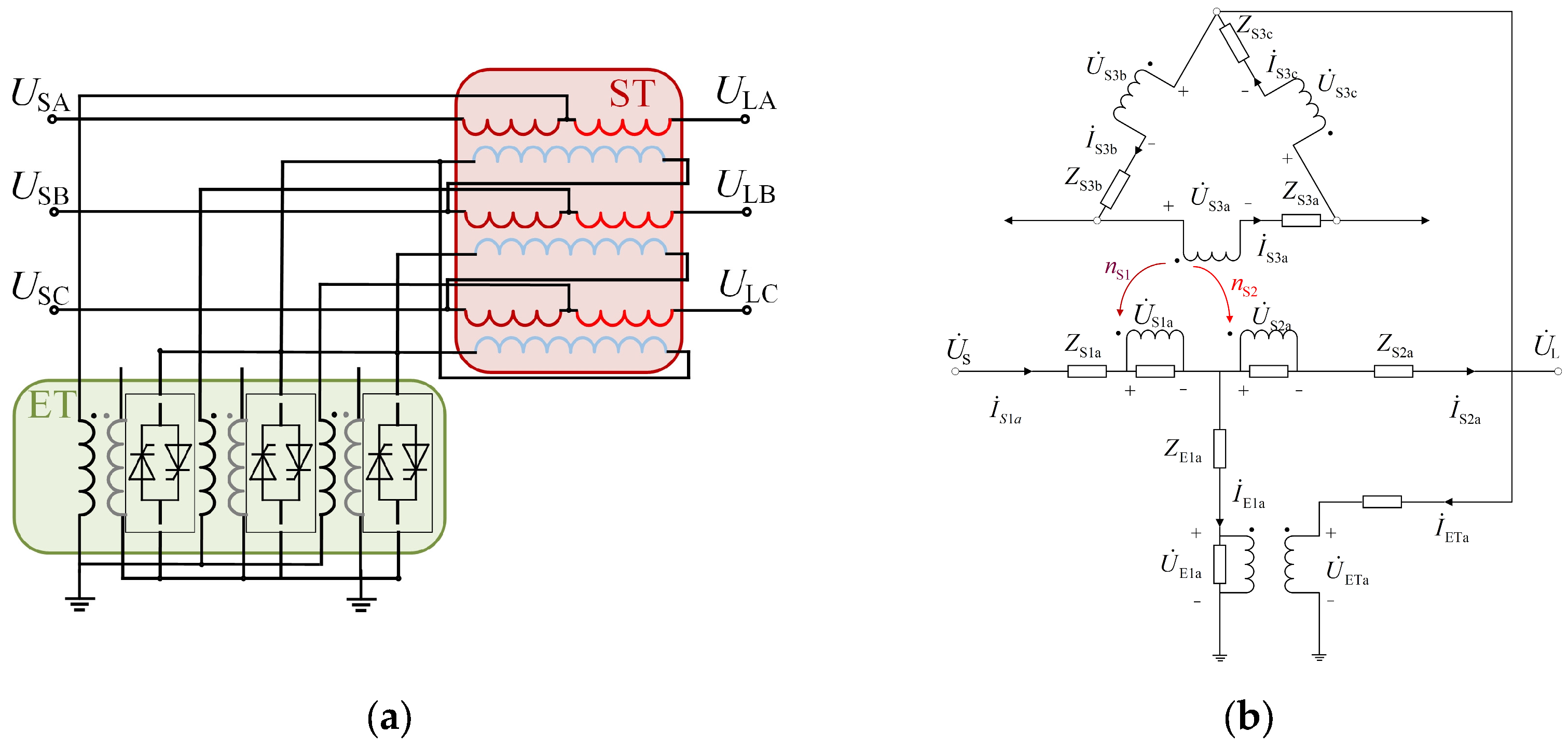
4. Voltage Step-Down and Phase-Shifting Capability Calculations of the SCSUD-TCPST

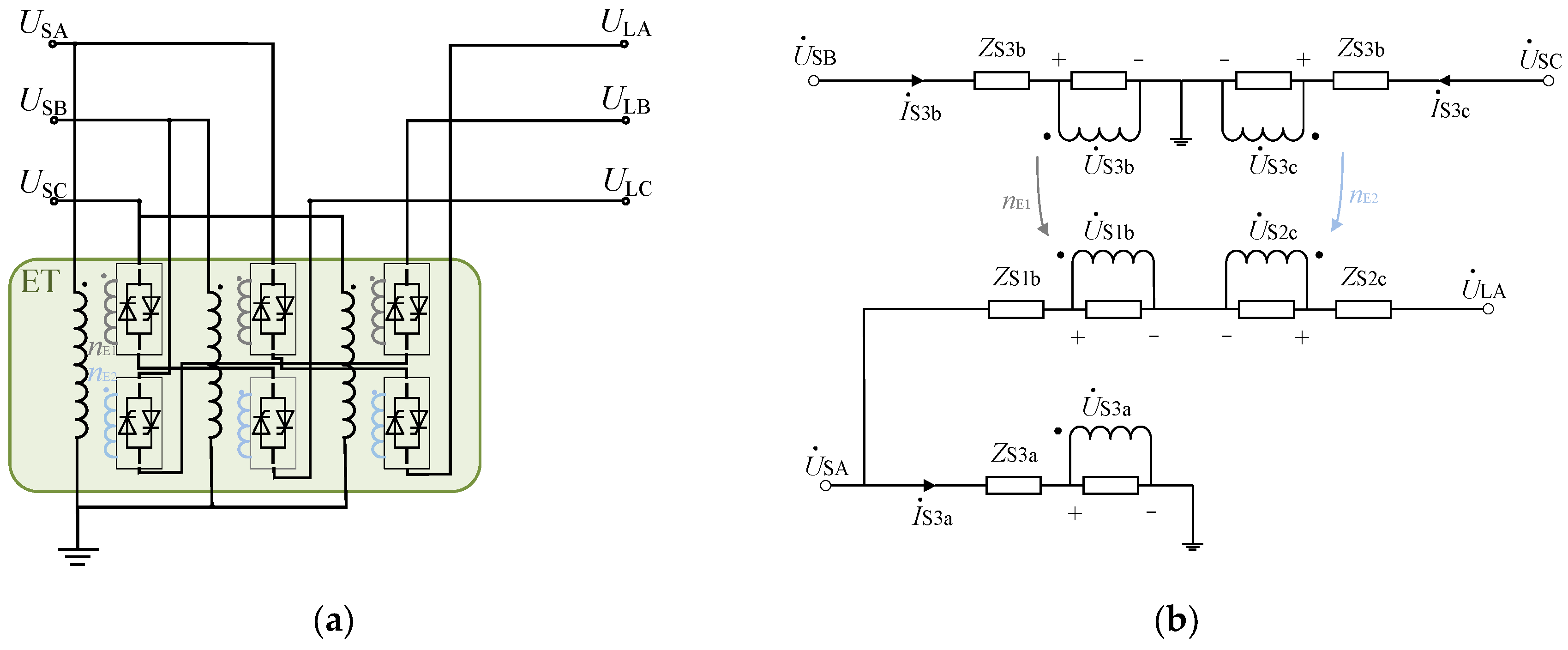
4.1. Topology Structure of SCSUD-TCPST

As shown in Figure 4a and Figure 6a, the SCSUD-TCPST topology structure was modified to integrate the ST of TCSUD-TCPST into the ET. This integration entailed adjusting the phase-shifting angle and the amplitude of the UL by modifying the values of nE1 and nE2.

4.2. Calculation of the Phase-Shifting Angle and the Amplitude

As shown in Figure 6, the voltage phasor relationship between the input and the output of the SCSUD-TCPST is as follows:
U ˙ L = U ˙ S ( 1 + n E 1 e j 2 π 3 + n E 2 e j 2 π 3 )
where nE1 and nE2 are the ratio of turns of the winding of excitation transformers, respectively.
The output voltage phasor in Equation (19) can be decomposed into the real part and the imaginary part as follows:
Re ( U ˙ L ) = U S ( 1 1 2 ( n E 1 + n E 2 ) )
Im ( U ˙ L ) = U S ( 3 2 ( n E 1 + n E 2 ) )
The input voltage phasor can also be expressed as follows:
U ˙ L = U L e j φ = U L ( cos φ + j sin φ )
The output voltage phasor in Equation (18) can be decomposed into the real part and the imaginary part as follows:
Re ( U ˙ L ) = U L cos φ
Im ( U ˙ L ) = U L sin φ
By combining Equations (20) with (23) and Equations (21) with (24), the phase-shifting angle and the amplitude of the UL can be derived as follows:
φ = Arctan ( 1 1 2 ( n E 1 + n E 2 ) , 3 2 ( n E 1 n E 2 ) )
U L U S = ( 1 1 2 ( n E 1 + n E 2 ) ) cos ( Arctan ( 1 1 2 ( n E 1 + n E 2 ) , 3 2 ( n E 1 n E 2 ) ) )
In light of the actual adjustment requirements, the value of nE1 and nE2 can be calculated according to the phase-shifting angle φ and the amplitude ratio UL/US as follows:
n E 1 = 1 U L U S ( cos φ + 3 3 sin φ ) [ 1 U L U S 2 3 3 , 1 + U L U S 2 3 3 ] n E 2 = 1 U L U S ( cos φ 3 3 sin φ ) [ 1 U L U S 2 3 3 , 1 + U L U S 2 3 3 ]
As indicated in Equation (25), when the values of nE1 and nE2 are equal, the phase-shifting angle is 0, thereby enabling the SCSUD-TCPST to operate in the voltage amplitude regulation mode. When the values of nE1 and nE2 are not necessarily equal, as indicated in Equation (27), the range of the phase-shifting angle of the SCSUD-TCPST can cover the whole ±180° when the values of nE1 and nE2 are not over 1 + 2(UL)/(US (3)(1/2)), which is generally less than 3. This allows the SCSUD-TCPST to reach the capability of all ranges of phase shifting and amplitude regulation.
Furthermore, the ratios of transformers in SCSUD-TCPST in Equation (27) are linearly proportional to the amplitude of the voltage and are sinusoidal to the phase-shifting angle. This makes it more convenient for thyristor-controlled regulation than TCSUD-TCPST.

5. Simulations and Experiments

To further verify the correctness and validity of the aforementioned analysis of PSTs, a simulation was constructed using the power transmission system shown in Figure 2 on PLECS. The relative system parameters and PST parameters are shown in Table 1 and Table 2, respectively.
As shown in Figure 1b, each group of thyristors within TCPST comprises four groups of anti-parallel thyristors arranged in a H-bridge configuration. Therefore, the forward voltage, reverse voltage, and zero voltage of the secondary winding voltage can be output, respectively, by controlling the on and off states of the bridge arm of the H-bridge. Generally, the secondary winding ratio of TCPST can be set as 1:3:9 [16]. Therefore, each transformer in TCPST delivers 27 adjustment gears. Consequently, the ratios of transformers of SCSUD-TCPST can be set as follows:
n E 1 = n E 2 = 1 U L U S 2 3 3 + U L U S 2 3 39 k , k { 0 , 1 , 2 , , 26 }
where k is the number of the gear, which is determined by the specific value of the voltage amplitude and phase-shifting angle. The detailed parameters of the ratios of transformers in the simulation in this section are shown in Table 3.

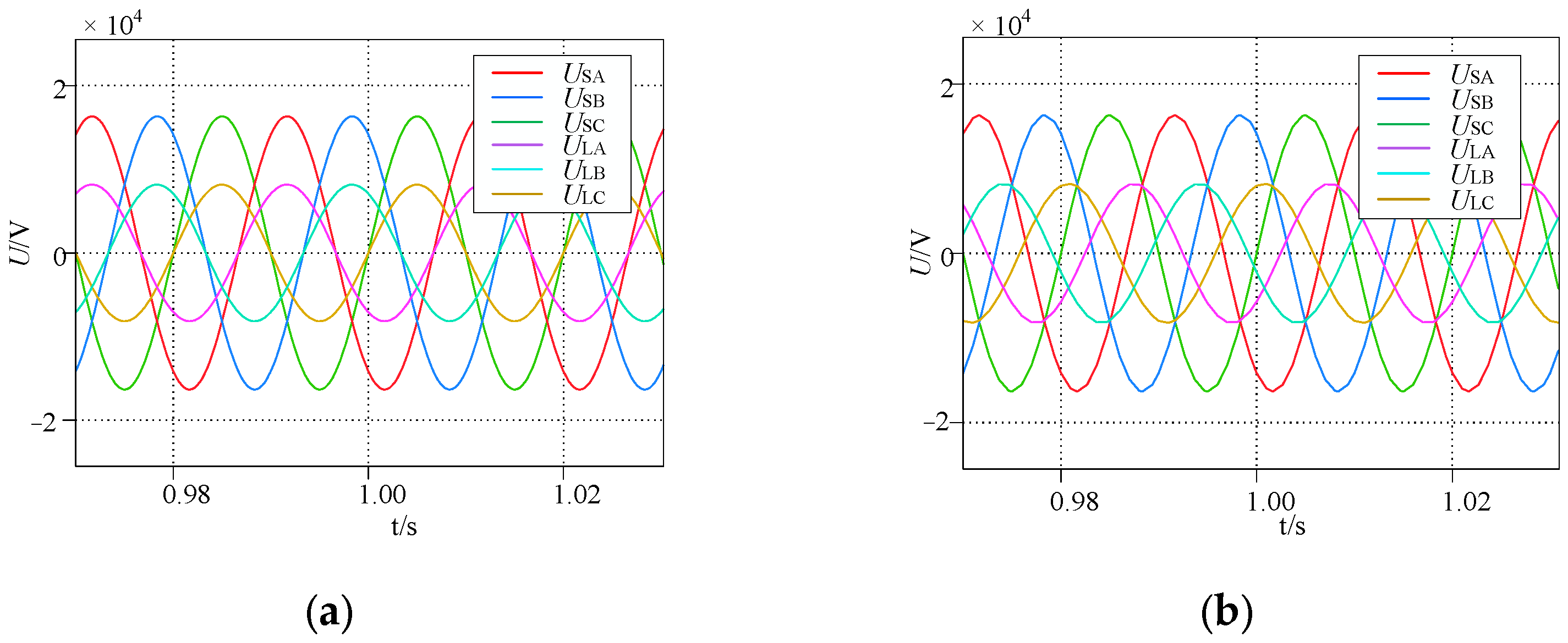
5.1. Comparative Static Performance Simulation of TCSUD-TCPST and SCSUD-TCPST

As shown in Figure 7 and Figure 8, SCSUD-TCPST and TCSUD-TCPST both have relatively excellent phase-shifting characteristics. As for their amplitude regulation characteristics, the step-up/down voltage amplitude and the phase-shifting angle of the SCSUD-TCPST can be decoupled by (25) and (26) and regulated by nE1 and nE2, which allows the amplitude of the UL to be regulated to 0.5 p.u. with the arbitrary phase-shifting angle, as shown in Figure 8a. Meanwhile, due to the coupling relationship between the amplitude and the phase-shifting angle of the TCSUD-TCPST, as shown in Figure 8b, when the TCSUD-TCPST is controlled to achieve a 0.5 p.u. step-down voltage, its phase-shifting angle is limited and cannot be 0, which is consistent with the aforementioned conclusion.
As shown in Table 4, static adjustment errors of the voltage amplitude and phase-shifting angle are utilized as comparative benchmarks to facilitate further analysis of the characteristics of SCSUD-TCPST and TCSUD-TCPST. Although TCSUD-TCPST has an evident phase-shifting angle when regulating voltage amplitude, both SCSUD-TCPST and TCSUD-TCPST have negligible error (<1.0%) when regulating the voltage amplitude and phase-shifting angle.

5.2. Comparative Dynamic Performance Simulation of TCSUD-TCPST and SCSUD-TCPST

As shown in Figure 9 and Figure 10, the output active power of TCSUD-TCPST and SCSUD-TCPST is required to be regulated from 100 MW to 50 MW at 2 s. The voltage waveform of TCSUD-TCPST and SCSUD-TCPST around 2 s indicates that they can be regulated smoothly and rapidly through thyristor control, and the active power can reach the target value within 0.2 s with minimal current oscillation. Compared with Figure 9 and Figure 10, SCSUD-TCPST exhibits superior dynamic performance in comparison with TCSUD-TCPST, which demonstrates reduced power and current oscillation. This finding further verifies that SCSUD-TCPST is more recommended for engineering applications.
As shown in Table 3, the ratios of the transformers of SCSUD-TCPST are smaller than those of TCSUD-TCPST. This indicates that it is more economical to expand the capacity of SCSUD-TCPST than TCSUD-TCPST [16]. As shown in Table 5, the maximum ratios of transformers in the simulation condition of TCSUD-TCPST are twice larger than those of SCSUD-TCPST, thereby further verifying the superiority of SCSUD-TCPST for engineering applications, considering cost and scalability.

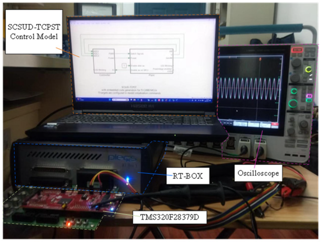
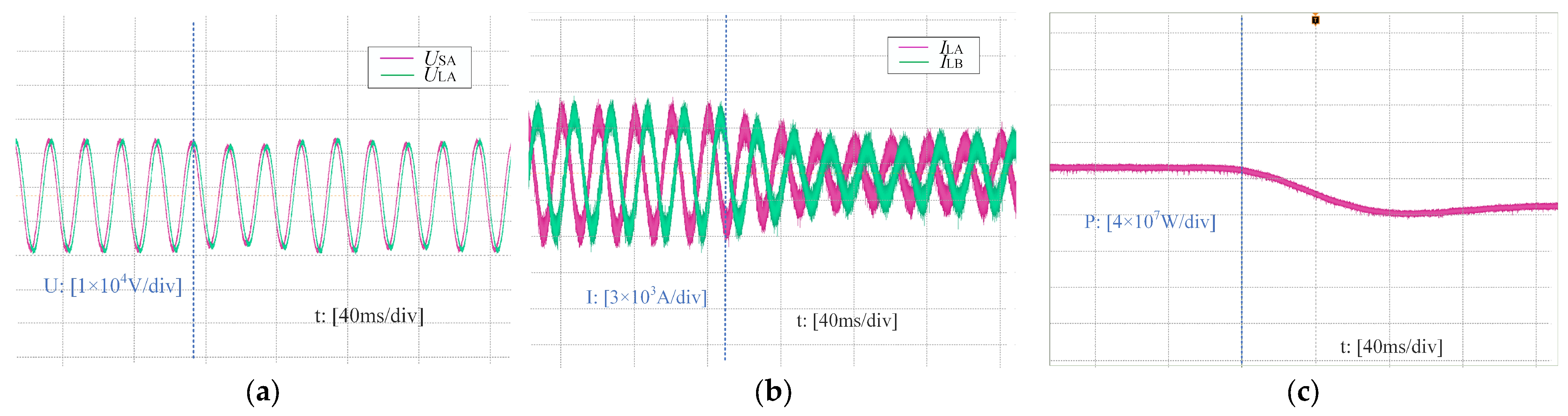
5.3. Hardware-in-Loop Experiments Based on RT-BOX

As shown in Figure 11, the aforementioned simulation results were further verified by the hardware-in-loop experimental platform based on RT-BOX and TMS320F28379D. As shown in Figure 12, the output active power of SCSUD-TCPST is required to be regulated from 100 MW to 50 MW under the parameters shown in Table 6. These results further verify that the SCSUD-TCPST possesses sufficient dynamic characteristics and is well suited for applications in power flow control.

6. Conclusions

This study proposed and compared two distinct structures of TCPSTs, namely the TCSUD-TCPST and the SCSUD-TCPST, which are capable of regulating both the phase-shifting angle and the amplitude of voltages. The conclusions are as follows:
  • The coupling relationship between the phase-shifting angle and the amplitude of voltages of the TCSUD-TCPST restricts the range of possible regulation, rendering the regulation process nonlinear;
  • The SCSUD-TCPST merges the ST into the ET, thereby simplifying the topology structure, decoupling the relationship between the phase-shifting angle and the amplitude, expanding the range, and linearizing the regulation process;
  • Both the TCSUD-TCPST and the SCSUD-TCPST have similar and considerable static and dynamic characteristics in power transmission;
  • In conclusion, compared to the TCSUD-TCPST, the SCSUD-TCPST appears to be a more suitable option for power transmission.

Author Contributions

Methodology, N.Z.; Resources, H.L.; Writing—original draft, X.J.; Writing—review & editing, C.B.; Validation, J.W. All authors have read and agreed to the published version of the manuscript.

Funding

This study is supported by the science and technology project of State Grid Jiangsu Electric Power Co., Ltd. under Grant J2024016.

Data Availability Statement

The original contributions presented in the study are included in the article, further inquiries can be directed to the corresponding author.

Conflicts of Interest

Authors Ningyu Zhang and Huarui Li were employed by the company State Grid Jiangsu Electric Power Co., Ltd. The remaining authors declare no conflicts of interest. The funders had no role in the design of the study; in the collection, analyses, or interpretation of data; in the writing of the manuscript; or in the decision to publish the results.

References

  1. Gomis-Bellmunt, O.; Sau-Bassols, J.; Prieto-Araujo, E.; Cheah-Mane, M. Flexible Converters for Meshed HVDC Grids: From Flexible AC Transmission Systems (FACTS) to Flexible DC Grids. IEEE Trans. Power Deliv. 2020, 35, 2–15. [Google Scholar] [CrossRef]
  2. Shan, P.; Sun, Y.; Song, Y.; Zhang, F.; Li, Y.; Sun, K. Adaptive Parameter Tuning and Virtual Impedance Injection Control for Coupled Harmonic Mitigation of Photovoltaic Converter. IEEE Trans. Power Electron. 2025, 1, 162–175. [Google Scholar] [CrossRef]
  3. Hussain, J.; Huang, Q.; Li, J.; Hussain, F.; Manzoor, K.; Ahmed, S.A. Enhancing Power Quality in Grid Integration of Wind Energy System Using UPFC-BESS. In Proceedings of the 2023 13th International Conference on Power and Energy Systems (ICPES), Chengdu, China, 8–10 December 2023; pp. 453–458. [Google Scholar]
  4. Jagtap, P.; Chandrakar, V. Advanced UPFC Controllers to Improve Transient and Dynamic Stability of Power System. J. Phys. Conf. Ser. 2024, 1, 2763. [Google Scholar]
  5. Imdadullah; Ammr, S.M.; Jamil Asghar, M.S.; Ashraf, I.; Meraj, M. A Comprehensive Review of Power Flow Controllers in Interconnected Power System Networks. IEEE Access 2020, 8, 18036–18063. [Google Scholar] [CrossRef]
  6. Biswas, S.; Nayak, P.K. A Fault Detection and Classification Scheme for Unified Power Flow Controller Compensated Transmission Lines Connecting Wind Farms. IEEE Syst. J. 2021, 15, 297–306. [Google Scholar] [CrossRef]
  7. Xu, Z.; Tang, J.; Jiang, Y.; Qin, R.; Ma, H.; Yang, Y.; Zhao, C. Analysis of Fault Characteristics of Distribution Network with PST Loop Closing Device Under Small Current Grounding System. Energies 2022, 15, 2307. [Google Scholar] [CrossRef]
  8. Zheng, S.; Wang, J.; Wang, F.; Tolbert, L.M. DC-Saturated Continuously Variable Series Reactors (CVSRs) for Power Flow Control in Power Transmission Systems. IEEE Trans. Power Deliv. 2022, 37, 268–278. [Google Scholar] [CrossRef]
  9. Sakallıoğlu, B.; Esenboğa, B.; Demirdelen, T.; Tümay, M. Performance Evaluation of Phase-shifting Transformer for Integration of Renewable Energy Sources. Electr. Eng. 2020, 102, 2025–2039. [Google Scholar] [CrossRef]
  10. Jin, W.; Liu, H.; Zhang, W.; Yuan, J. Power Flow Regulation Effect and Parameter Design Method of Phase-Shifting Transformer. Energies 2024, 17, 1622. [Google Scholar] [CrossRef]
  11. Brilinskii, A.S.; Badura, M.A.; Evdokunin, G.A.; Chudny, V.S.; Mingazov, R.I. Phase-Shifting Transformer Application for Dynamic Stability Enhancement of Electric Power Stations Generators. In Proceedings of the 2020 IEEE Conference of Russian Young Researchers in Electrical and Electronic Engineering (EIConRus), St. Petersburg and Moscow, Russia, 27–30 January 2020; pp. 1176–1178. [Google Scholar]
  12. Ding, T.; Bo, R.; Bie, Z.; Wang, X. Optimal Selection of Phase Shifting Transformer Adjustment in Optimal Power Flow. IEEE Trans. Power Syst. 2017, 3, 2464–2465. [Google Scholar] [CrossRef]
  13. Liang, G.; Wang, L.; Gao, F.; Liu, X. A New Maximum Step Voltage Calculation Method of On-Load Tap-Changer for Symmetrical Two-Core Phase-Shifting Transformer. IEEE Trans. Power Deliv. 2018, 6, 2718–2725. [Google Scholar] [CrossRef]
  14. Luo, M.; Dujic, D.; Allmeling, J. Leakage Flux Modeling of Medium-Voltage Phase-Shift Transformers for System-Level Simulations. IEEE Trans. Power Electron. 2019, 3, 2635–2654. [Google Scholar] [CrossRef]
  15. Yuan, J.; Zhang, W.; Mei, J.; Gan, D.; Zhou, H.; Zheng, Y. Independent Fast Phase Shifting Transformer: A Flexible and High-Precision Power Flow Controller. IEEE Trans. Power Deliv. 2023, 6, 4410–4421. [Google Scholar] [CrossRef]
  16. Liu, J.; Hao, X.; Wang, X.; Chen, Y.; Fang, W.; Niu, S. Application of thyristor controlled phase shifting transformer excitation impedance switching control to suppress short-circuit fault current level. J. Mod. Power Syst. Clean Energy 2018, 4, 821–832. [Google Scholar] [CrossRef]
Figure 1. (a) Mechanical tapping structure of MPST; (b) thyristor control structure of TCPST.
Energies 18 00837 g001
Figure 2. Equivalent schematic diagram of a transmission line after installing a TCPST.
Energies 18 00837 g002
Figure 3. The voltage phasor variation relationship of TCPST.
Energies 18 00837 g003
Figure 4. (a) Topology structure of TCSUD-TCPST; (b) a phase-equivalent circuit diagram of TCSUD-TCPST.
Energies 18 00837 g004
Figure 5. (a) Voltage phasor relationship of TCSUD-TCPST with an equal value of ns1 and ns2; (b) voltage phasor relationship of TCSUD-TCPST with different values of ns1 and ns2.
Energies 18 00837 g005
Figure 6. (a) Topology structure of SCSUD-TCPST; (b) a phase-equivalent circuit diagram of SCSUD-TCPST.
Energies 18 00837 g006
Figure 7. (a) The 30° phase-shifting voltage waveform of the SCSUD-TCPST; (b) the 30° phase-shifting voltage waveform of the TCSUD-TCPST.
Energies 18 00837 g007
Figure 8. (a) The 0.5 p.u. step-down voltage waveform of the SCSUD-TCPST; (b) the 0.5 p.u. step-down voltage waveform of the TCSUD-TCPST.
Energies 18 00837 g008
Figure 9. Power flow regulating waveforms of TCSUD-TCPST at 2 s: (a) the voltage waveform; (b) the current waveform; (c) the active power waveform.
Energies 18 00837 g009
Figure 10. Power flow regulating waveforms of SCSUD-TCPST at 2 s: (a) the voltage waveform; (b) the current waveform; (c) the active power waveform.
Energies 18 00837 g010
Figure 11. Hardware-in-loop experimental platform based on RT-BOX.
Energies 18 00837 g011
Figure 12. Power flow regulating waveforms of SCSUD-TCPST: (a) the voltage waveform; (b) the current waveform; (c) the active power waveform.
Energies 18 00837 g012
Table 1. Parameters of the power transmission system.
Sending Voltage US (kV)Receiving Voltage UR (kV)Grid Impedance XL (mH)
20200.4
Table 2. Parameters of TCPSTs.
Rated Capacity SPST (MVA)Power Flow Capacity SP (MVA)Leakage Inductance L1 (mH)
100±6010
Table 3. Parameters of ratios of transformers.
FigurenE1/nS1nE2/nS2
Figure 7a−0.1550.423
Figure 7b2.1552.155
Figure 8a0.4670.467
Figure 8b−0.1552.155
Figure 92.155 → 2.0662.155 → 2.155
Figure 10−0.155 → −0.0660.6006 → 0.7782
Table 4. Static adjustment errors.
FigureActual Angle (°)Angle Error (%)Actual Amplitude (p.u.)Amplitude Error (%)
Figure 7a29.910.301.0000.00
Figure 7b29.920.271.0000.00
Figure 8a0.01\0.4970.60
Figure 8b97.71\0.4970.60
Table 5. Cost comparison of TCSUD-TCPST and SCSUD-TCPST.
SCSUD-TCPSTTCSUD-TCPST
Maximum ratios0.77822.155
Table 6. Parameters of experiments of SCSUD-TCPST.
ParametersValuesParametersValues
Sending voltage US (kV)20Receiving voltage UR (kV)20
Grid impedance XL (mH)
nE1
0.40
−0.155 → −0.066
Active power flow (MW)
nE2
100 → 50
0.6006 → 0.7782
Disclaimer/Publisher’s Note: The statements, opinions and data contained in all publications are solely those of the individual author(s) and contributor(s) and not of MDPI and/or the editor(s). MDPI and/or the editor(s) disclaim responsibility for any injury to people or property resulting from any ideas, methods, instructions or products referred to in the content.

