Article

Composite Power Management Strategy for Hybrid Powered Compound-Wing Aircraft in Level Flight

1
College of Electrical Engineering, Sichuan University, Chengdu 610065, China
2
Institute of Electronic and Electrical Engineering, Civil Aviation Flight University of China, Guanghan 618307, China
*
Author to whom correspondence should be addressed.
Energies 2025, 18(4), 799; https://doi.org/10.3390/en18040799
Submission received: 21 December 2024 / Revised: 19 January 2025 / Accepted: 6 February 2025 / Published: 8 February 2025
(This article belongs to the Section F: Electrical Engineering)

Abstract

:
A composite strategy is proposed to address the optimal power management for a hybrid powered compound-wing aircraft, which integrates bang–bang regulation with optimal demand chasing regulation. The electro-gasoline hybrid power system enhances the overall flight endurance of vertical take-off and landing compound-wing aircraft. The power consumption in level flight appears to be much lower than that in hovering, enabling the hybrid power system to simultaneously energize and charge the battery pack. In order to minimize fuel consumption and battery pack degradation during level cruise flight, a power management strategy that serves for both battery charging and thrust energizing is worthy of careful consideration. To obtain the desired features and design the regularity strategy of the power system, linear and nonlinear models are established based on the configuration of an electro-gasoline series hybrid power system installed in the proposed aircraft, with mathematical modelling of key components and units. A notable feature of semi-fixing for battery voltage and engine rotational speed has been qualitatively identified and subsequently quantitatively validated on the testbench. After conducting simulations and comparing with other strategies, the composite strategy demonstrates appropriate fuel consumption and battery degradation, effectively achieving cost minimization. Testbench evaluation confirms the effectiveness of this proposed power management strategy. Furthermore, the practicality of the hybrid power system and its associated level flight composite power management strategy are validated by tests conducted on a 30 kg aircraft prototype, thereby showcasing the potential to enhance flight performance.

1. Introduction

Compound-wing type vertical take-off and landing (VTOL) aircraft integrate a multi-rotor system with a fixed-wing configuration, combining the advantages of both configurations [1,2,3]. The specific advantages of this configuration include: the ability to hover for operations, long endurance, high flight speed, low takeoff and landing requirements, and large mission payload capacity, and the potential application scenarios for this configuration include logistics delivery, power line inspection, and security monitoring. The onboard power system must be capable of accommodating two distinct operational conditions throughout the entire flight profile, namely high-power vertical flight and low-power level cruise flight. In order to facilitate efficient power grid flight inspection and emergency logistics by air, both vertical and level flights are taken into consideration in the performance design. To effectively enhance flight endurance, various electro-gasoline or electro-fuel-cell hybrid power systems have been developed for VTOLs of this configuration, considering the relatively high energy density of fuel. In the research of airborne hybrid power systems, a variety of design and improvement methods are applied to enhance the efficiency and reliability of the power system, specifically focusing on battery management [4,5], power generation [6,7,8,9], and power transmission [10,11,12,13,14]. This technology has been extensively employed in numerous industrial-class multi-rotor vehicles [15,16], where a hybrid power system combining an inner combustion engine (ICE) with a generator and battery packs offers significantly longer hovering duration compared to pure electric systems, owing to the superior energy density provided by fossil fuels [17]. Furthermore, with regard to VTOL power supply systems, it is worth noting that while DC/DC converters excel in electricity transmission, they incur a significant weight penalty due to their low power density [18,19,20,21,22,23].
To enhance flight range and duration, the utilization of a series hybrid electric propulsion system has gained attention in recent years for VTOL, particularly compound-wing configurations [24,25]. Throughout the entire flight profile, the ICE can consistently operate within its optimal fuel economy range. Additionally, during level cruise flight, the ICE-generator assembly is also responsible for supplying a portion of the energy required to recharge the battery. The deployment of electricity from generators and battery packs incorporates power management strategies during level flight of compound-wing VTOL, effectively balancing the costs associated with fuel consumption and battery degradation.
For a hybrid power system, the development of an effective power management strategy is considered one of the fundamental techniques, extensively explored in various studies. Scholars have categorized these strategies into two types: optimization-based and rule-based approaches.
Optimization-based strategies encompass Pontryagin’s minimum principle, Lagrange multipliers, equivalent consumption minimization, and dynamic programming [26,27]. These methods aim to find the optimal control input sequence to minimize a certain cost function. Consider an example from this study, they might be used to minimize fuel consumption and battery degradation simultaneously. By leveraging mathematical optimization techniques, they can theoretically determine the most efficient way to allocate power between different components of the hybrid power system. However, these methods need an accurate system model. In aircraft applications, where conditions are complex and uncertain, getting such a model is tough. Additionally, their high computational complexity can make it hard to provide real-time control decisions, which is crucial for the compound-wing VTOL in this article.
On the other hand, rule-based strategies involve state machines, fuzzy logic systems, and power follows [28,29]. These strategies are based on predefined rules and logic. State machines operate based on different system states, fuzzy logic systems handle uncertainties by using fuzzy sets and rules, and power follow strategies adjust power output based on power demand. The shortcomings are also obvious, their performance depends on the quality of the rules. Designing rules to cover all operating scenarios, like those of the compound-wing VTOL, is challenging. This can lead to suboptimal power management in terms of fuel consumption and battery degradation.
The limitations of existing strategies, including the high computational complexity associated with optimization-based methods and the restricted adaptability of rule-based approaches, necessitate the development of a more effective and practical strategy. To this end, this paper introduces a composite power management strategy for level cruise flight in compound-wing VTOL aircraft powered by a direct-connected electro-gasoline hybrid power system. This strategy integrates optimization-based and rule-based methodologies to leverage their respective strengths, thereby enhancing performance in minimizing fuel consumption and mitigating battery degradation while preserving the system’s robustness and real-time control capabilities. Consequently, the proposed composite power management strategy aims to achieve an overall reduction in both fuel consumption and battery pack degradation, thus optimizing cost-efficiency.
The subsequent sections of this article are organized as follows: Section 2 presents the modelling and linearization of the architecture for the proposed hybrid power system, with a focus on key components and notable features. Section 3 provides a composite power management strategy, based on the definitions of regulations and mechanism of battery pack degradation. The experimental environment is described, and experimental results are presented in Section 4, followed by concluding remarks in Section 5.

2. Architecture of Hybrid Power System

2.1. Layout of VTOL and Hybrid Power System

The VTOL is depicted in Figure 1, featuring a compound configuration of multi-rotor and fixed-wing, and the designed UAV has a maximum take-off weight of 30 kg and a peak power of 7 kW. In the multi-rotor mode, the VTOL ascends vertically with four rotor wings driven by four motors, which are powered by both a battery pack and generator. To meet long-range cruising requirements, the VTOL transitions to fixed-wing mode utilizing lift generated from classical wings and thrust provided by an ICE-driven propeller as well as motor-driven propellers on the wings. During level cruise flight, the wing-mounted motors are powered by the generated electricity which simultaneously charges the battery pack.
The proposed layout of an electro-gasoline hybrid power system is illustrated in Figure 1, which adopts a series configuration to enhance power efficiency and reduce take-off weight. A specialized high-speed permanent magnetic generator is coaxially mounted onto one end of the crankshaft of ICE, while the other end drives a fixed-pitch propulsion propeller for cruise level flight. AC power is rectified into DC power by fast-recover diodes inside the rectifier. The battery pack is directly connected in parallel between the rectifier and electrical load (electronic speed controllers and motors), without requiring a DC/DC converter. The power source and propulsion system are decoupled, allowing the power generation system to operate within its optimal working range. In this condition, the engine operates with higher thermal efficiency, ensuring better working conditions, which maximizes emission reduction and extends the lifespan of the system.
The typical flight profile of the VTOL is illustrated in Figure 2. Throughout the entire flight process, the VTOL undergoes multiple take-offs and landings. The generator operates in extended-range mode. During each vertical flight phase, the power demand exceeds the maximum generated power, resulting in battery pack discharge and a subsequent decrease in state of charge (SOC). However, upon transforming to level cruise flight phase, the power demand reduces to one-third or less of its previous value. At this stage, it becomes feasible to charge the battery pack using excess generator power.
For a compound-wing VTOL, the power demand for hovering or vertical flight is typically several times higher than the power demand during level cruise flight. The generated power is optimized to fall between the power requirements for hovering and cruising, ensuring that SOC decreases during vertical flight while allowing for battery pack recharging during level cruise flight.

2.2. Modelling of Hybrid Power System

The combustion of gasoline within the cylinders induces reciprocating motion of the pistons, resulting in torque generation at the crankshaft. This torque is primarily influenced by throttle opening and rotational speed (or represented by revolutions per minute, RPM), which can be mathematically represented as a cubic polynomial equation denoted by Equation (1). Additionally, an inertial term is incorporated into Equation (1) to account for the effects of combustion and heat transfer.
T I C E + τ T ˙ I C E = f n s , α = i = 0 3 j = 0 3 b i , j n s i α j
where T I C E , n s , and α are the ICE output torque, the shaft rotational speed, and the ICE throttle opening, respectively. τ is the inertial term coefficient and b i , j is the constant of ICE torque expression.
The torque balance on the crankshaft is expressed as Equation (2).
π 30 J s n ˙ s = T I C E T P n s T G Ω n s
where J s , T P , and T G are the inertia of all assemblies linked onto ICE crankshaft, the torque of propeller, and the Generator input torque, respectively. Ω is the coefficient of friction torque in ICE.
As the shaft speed is almost locked around a specific rotational speed, the output torque from ICE shows a linear relationship of throttle opening, as in Equation (3).
T I C E = f n s , α k a α
where k a is the coefficient of throttle opening.
The torque generated by the fix-pitch propeller can be modelled as a quadratic polynomial of rotational speed (RPM), represented by Equation (4).
T P ( n s ) = η 0 + η 1 n s + η 2 n s 2
η 0 , η 1 , and η 2 represent the coefficients of the quadratic polynomial.
The relationships among the generator, rectifier, battery pack, and electrical load adhere to Kirchhoff’s laws as expressed by Equations (5) and (6).
L d i G d t = φ n s i L R r U c i G i L R b a t t
c d U c d t = i L U c R b a t t
where L , φ , R r , and R b a t t are the winding inductance inside generator, the counter electromotive force constant, the equivalent resist in generator and rectifier, and the internal resistance of the battery, respectively. i G , i L , U c and c represent the generator DC current, the loading current, the output DC voltage, and the equivalent capacitance, respectively.
The torque of the generator is determined by the flux linkage and pole-pairs, as described in Equation (7). Under static operation conditions, the generated torque shows a direct proportionality to the armature current.
T G = 3 2 p p ψ i q L d L q i q i d k T i G
where p p , and ψ are the pole-pairs inside the generator and the flux linkage inside the generator, respectively. L d and L q are the inductances of the d -axis and q -axis. i d and i q are the current of d-axis and q-axis. k T is the coefficient of generated torque.
Therefore, the linearized depictions of shaft speed, battery current, and voltage are expressed by Equation (8).
d n s d t = 30   η π J s + Ω n s 30 k T π J s i G + 30 k a π J s α d i G d t = R b a t t L i G + φ L n s R r R b a t t L i L 1 L U c d U c d t = 1 R b a t t U c + 1 c i L
where η is the torque coefficient of the propeller near the linearization point.
The nonlinear model of the combination of ICE, generator, rectifier, battery pack, and electrical load is expressed from (1) to (7), and the linear model can be expressed as (9) from (8).
The generated power is dependent on the shaft power output from ICE, which is influenced by factors such as shaft speed, throttle opening, and battery pack voltage. Consequently, the steady-state specific fuel consumption can be accurately represented using Figure 3, which shows the fuel consumption rate varies with generated power, at one specific voltage.
d n s d t d i G d t d U c d t = 30 η π J s + Ω 30 k T π J s 0 φ L R batt L 1 L 0 0 1 R batt n s i G U c + 30 k a π J s 0 0 R batt R r L 0 1 c α i L i batt U c = 0 1 0 0 0 1 n s i G U c + 0 1 0 0 α i L
where i batt is the current of battery pack.

2.3. One Notable Feature of the Architecture

Because of the considerable battery capacitance, the voltage from the battery is regarded as constant at any given moment, taking the transient behavior of capacitors into account.
ICE’s shaft speed is symmetric with the generator and proportional with the electromagnetic frequency. As the shaft speed rises while ICE’s power remains unchanged, the output current from the generator rises rapidly and synchronously. The rising current increases onto loading torque, and the shaft speed is consequently pulled back, and vice versa.
Particularly, due to the one-way energy flow characteristics of the rectifier, in the event of an uncontrolled descent in shaft speed, the output voltage drops below that of the battery and consequently results in a significant reduction in current. From the demonstration in (10), this leads to an almost negligible torque from the generator and prompts a rapid recovery in shaft speed, potentially causing internal combustion engine racing or overspeeding.
T G = k T i G , U G > U c 0 , U G U c
where U G is the generator DC voltage. As ICE’s power (tuned by throttle opening) varies controllably, shaft speed is still chained by the voltage from the battery, and it is reflected in the change of torque. Consequently, the current changes to balance ICE torque’s changing.
In summary, the parallel connection of the battery semi-fixes the shaft speed at which both ICE and generator’s shaft can operate, ensuring that the voltage generated by the generator remains slightly higher than that of the battery.

3. Power Management Strategy of Level Cruise Flight

3.1. BANG–BANG Regulation Definition

It is quite difficult to solve the optimal input sequence. The rule-based approach employed in this study is the bang–bang control strategy, which provides a practical solution. This method involves regulating the input between two extreme values to maintain a target condition. Specifically, the implementation of bang–bang control aims to keep the battery voltage within a specified range around the desired value. When the battery voltage reaches the lower threshold and its rate of change is negative, the throttle opening of the ICE is set to its maximum value. Conversely, when the voltage reaches the upper threshold and its rate of change is positive, the throttle opening is adjusted to its minimum value.
To keep the voltage around the demand, the bang–bang regulation is designed with a relay as in Equation (11).
u ( t ) = α m a x , U c = = U c m i n   and   d U c d t < 0 α m i n , U c = = U c m a x   and   d U c d t > 0
where u ( t ) is the input in period t; α m a x and α m i n are, respectively, the upper and lower limits of ICE throttle opening. U c m i n and U c m a x are the upper and lower limits of output DC voltage, respectively.

3.2. Optimal Chasing Regulation Definition

While in cruise flight, the VTOL operates in a series hybrid mode, where the ICE drives a generator to power the thrust motors and simultaneously charge the battery, utilizing the rest generated power. The DC voltage of the battery increases with the state of charge (SOC). The optimization-based approach entails employing mathematical optimization techniques to determine the optimal control input sequence that minimizes a specified cost function. In this case, the LQG regulation method is adopted, designed to achieve efficient battery charging within a finite time horizon while simultaneously minimizing state oscillation and fuel consumption. The LQG cost function is defined by Equation (12), comprises a combination of the discrepancy between the system output and the desired output, as well as a term associated with the control effort.
m i n u J = 1 2 y t f y ~ t f T S y t f y ~ t f + 1 2 t 0 t f y y ~ T Q y y ~ + u T R u d t s . t . x ˙ = A x + B u , x t 0 = x 0 y = C x = 1 0 0 U c n s i
where J is the cost, y is the output of the system and t f represents the final value time. R is positive, and Q, S are non-negative. A, B and C are, respectively, the system matrix, the control matrix, and the output matrix. The trajectory or servo demand is set as (13).
x ˙ = A x y ~ = C x
Matrices are augmented as (14).
x ~ = x x ,   x ~ t f = x t f x t f ,   A ~ = A 0 0 A ,   B ~ = B 0 Q ~ = C T Q C C T Q C C T Q C C T Q C ,   S ~ = C T S C C T S C C T S C C T S C
Therefore, the cost functional is converted to a normalized LQG form, as (15).
m i n u J = 1 2 x ~ T t f S ~ x ~ t f + 1 2 t 0 t f x ~ T Q ~ x + u T R u d t s . t . x ~ ˙ = A ~ x ~ + B ~ u , x ~ t 0 = x ~ 0
The optimal control input satisfies Equation (16).
u * = R 1 B ~ T P x ~
where positive matrix P is a solution of an algebraic Riccati Equation (17).
P A ~ + A ~ T P P B ~ R 1 B ~ T P + Q ~ = 0 P t f = S ~
Equation (12) is rewritten as Equation (18), considered a nonlinear controlled object with bounded input.
m i n u J = 1 2 y t f y ~ t f T S y t f y ~ t f + 1 2 t 0 t f y y ~ T Q y y ~ + u T R u d t s . t . x ˙ t = g x t , u t , t y t = h x t ,   u m i n u u m a x
The self-consistent Equation (19) with the optimal input that deducted from the LQG regulator can be obtained from Equations (15) and (16).
x ~ ˙ = ( A ~ B ~ R 1 B ~ T P ) x ~ , x ~ t 0 = x ~ 0
The stability of the LQG regulator is ensured when the coefficient matrix A ~ B ~ R 1 B ~ T P of the self-consistent equations is negative definite. In the case of a bang–bang regulator applied to nonlinear systems, Equation (3) reveals the presence of a linear control term, while the objective function incorporates a non-linear integrand. Moreover, considering that the components of the control vector are subject to bounds due to constrained throttle opening, stability is ensured within this system.

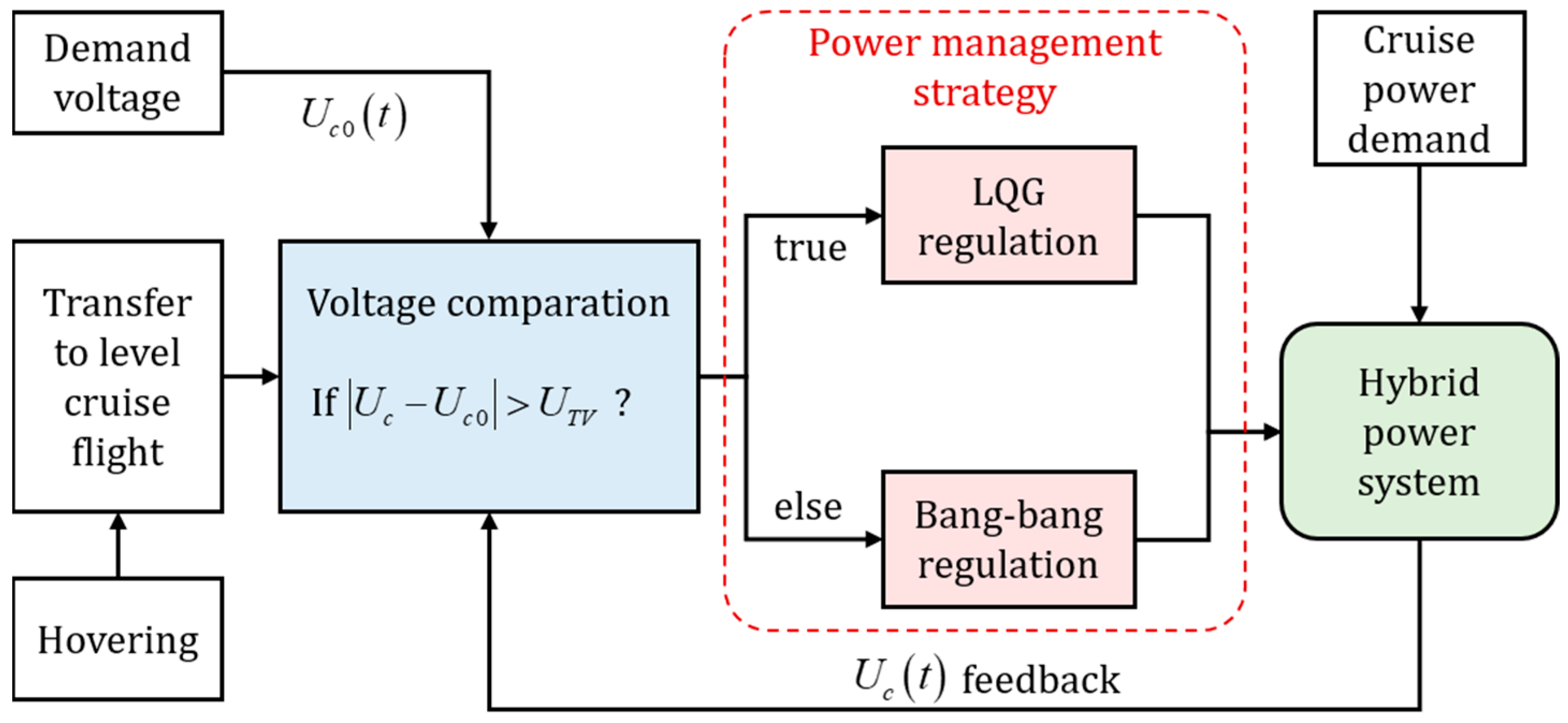
3.3. Power Management Strategy Definition

The composite power management strategy incorporates both an optimization-based method and a rule-based method to manage power distribution within the electro-gasoline hybrid power system of the compound-wing VTOL aircraft during level cruise flight. Illustrated in Figure 4, the power management strategy comprises two key components. When the real-time voltage of the battery pack deviates significantly from the demand value, the LQG regulation provides an optimal solution to minimize cost while increasing voltage. As the battery pack’s voltage reaches the demand once, a switch to bang–bang regulation occurs, where regulation is achieved using a relay, and voltage fluctuates repeatedly around the demand value.

3.4. Battery Degradation Definition

The service life of the battery pack, that is usually made by a Li-polymer, will decline sharply when the operating current exceeds the optimal rate, leading to a significant increase in cycle degradation, which is worth considering in the overall cost.
The degradation of battery satisfies the Arrhenius model [30], as in Equation (20).
ζ b a t t = ( γ 1 + γ 2 c r a t e ) e ( γ 3 + γ 4 c r a t e O A T ) Q t o t a l z
where ζ b a t t and Q t o t a l are, respectively, the degradation of battery pack and the total discharge capacity of battery pack. c r a t e represents the charge and discharge rate of the battery pack. γ 1 , γ 2 , γ 3 , and γ 4 are the constants of the Arrhenius model. The cost of the battery degradation satisfies Equation (21).
Π b a t t = ζ b a t t ( 1 κ b a t t ) λ b a t t
where Π b a t t is the cost of battery pack degradation. κ b a t t represents the maximum degradation limit coefficient of the power battery. To ensure the safe operation of the UAV, lithium power batteries are generally retired when their capacity drops below 70%. Consequently, this paper adopts a value of 0.7.

4. Results of the Experiment

4.1. Simulation Verification
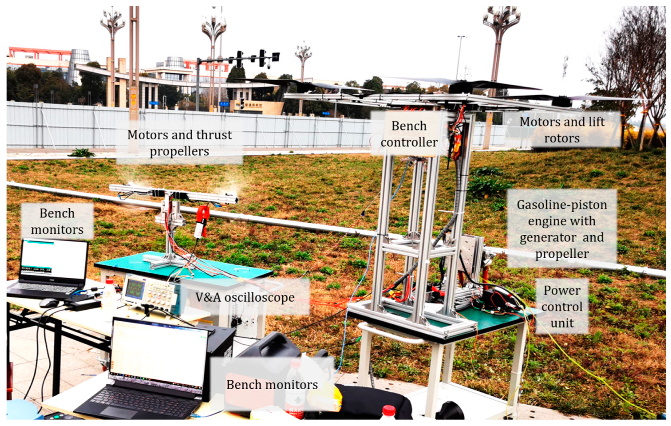
As depicted in Figure 5, the bang–bang and LQG strategies are implemented and validated through simulation. The bang–bang approach rapidly regulates the battery pack voltage from the initial stage, maintaining it within a fluctuating range around the desired value. In contrast, the LQG method ensures smoother voltage regulation with gradual variations in current and throttle opening. However, it is worth noting that the LQG strategy may not effectively address uncertainties related to flight range or endurance across all flight tasks or profiles, as shown Figure 6 and Figure 7.
These two simulations examine the requirements for VTOL operations under two flight profiles, each demanding different voltage levels. For example, to accomplish specific hovering tasks after level flight within a given profile, a higher demanded voltage is necessary. Conversely, when such tasks are not required, a lower voltage setting can be adopted, thereby conserving fuel used for power generation and battery charging.
As demonstrated in Table 1, the composite strategy shows a significantly slower charging rate compared to the Bang–bang only regulation, effectively striking a balance between fuel consumption and battery pack degradation.

4.2. Testbench

As depicted in Figure 8, a variable pitch propeller and a PM generator are coaxially mounted on both ends of the crankshaft of a 2-stroke, 2-cylinder piston engine. All major power components and their controller are installed on a specialized testbench to obtain performance data and validate the power management strategies.
The specialized testbench is equipped with adjustable power sources, lift/hovering simulation, and thrust simulation capabilities. The controllable power source derived from the generator/ICE ensures precise control over the experiment. Bench sensors and an oscilloscope are employed to monitor the charging or discharging rate of the battery, which can be fine-tuned by the bench controller. The simulated time-domain thrust and lift curves are configured to imitate practical flight profiles. Regarding the measurement parameters and methods, shaft speed is measured using sensors attached to the crankshaft of the ICE. Battery current and voltage are monitored with current and voltage sensors connected to the battery pack. Fuel consumption is tracked by monitoring the fuel flow rate during engine operation. Battery degradation is calculated using the Arrhenius model, where the charge and discharge rate of the battery pack are measured, and degradation is estimated using constants specific to the battery chemistry.

4.3. Typical Operation Conditions

The proposed VTOL aircraft takes off with a typical weight of 30 kg, a wingspan of 3.2 m, a fuselage length of 1.9 m, and a maximum payload capacity of 5 kg. It maintains a cruise speed of 27 m/s, while the drag force, which is equal to the total thrust, amounts to 8.6 kgf. The total thrust is generated by wing-mounted propellers and an ICE coaxially installed thrust propeller. Consequently, the power consumption of the wing-mounted propulsion motors depends on the thrust provided by the ICE-driven propeller.
The universal characteristics curve of ICE is acquired and shown in Figure 9. Considering both fuel efficiency and power output, the optimal range of rotational speed is selected within the range of 6000–7000 RPM.
The static relationship between thrust and power consumption from one of the propellers on the wings is shown in Figure 10, where the throttle value comes from the flight controller, and the practically used throttle value is set within 0.55–0.65.
Typical operation conditions for the power system are chosen as listed in Table 2.
The bench test was conducted to validate the feature of voltage-controlled shaft speed. The throttle opening was set at a fixed 70%, while the actual total thrust from the thrust motors was manually controlled. As depicted in Figure 11, both SOC and voltage gradually increased due to the charging of surplus power. From 600 s to 1000 s, despite significant variations in actual thrust (representing required power), the shaft speed remained constrained by voltage, resulting in minimal deviation within this time period.

4.4. Result Under Power Management Strategies

Thrust motors convert the flight profile shown in Figure 12 into power demand (loading power). When there are variations in battery voltage, the controller adjusts the throttle opening to regulate the output shaft power of the ICE accordingly.
The entire power system is linearized around a typical operation condition selected from Table 2. Based on Equations (12) to (17), an LQG controller is designed to track a demanded voltage of 49.9 V and 48.2 V, whose parameters are shown in Table 3.
As depicted from Figure 13 and Figure 14, five different strategies are conducted into the on-bench regulation tests. The LQG’s parameters are calculated off-line. Voltage under the LQG-only regulation reaches the demand after 600 s. The bang–bang-only regulates voltage most rapidly. The other three strategies combine smooth regulations with bang–bang. These strategies start with PID or LQG. Once voltage surpasses the lower limits, bang–bang is switched, and the real-time voltage oscillates around the demand. Within the bang–bang regulation, the battery pack’s current changes with a stepwise shape between the maximum charging value and level cruise pure-electric discharging value.
The bang–bang regulation switches the throttle opening to either 100% or 45% (the minimum for idle). The degradation is calculated by Equations (20) and (21) with time-domain absolute current from the battery pack (12 cells in series, 5800 mAh Li-polymer).
The on-bench regulation performances are compared in Table 4; despite the longer adjusting time, the strategy of LQG with bang–bang achieves the best overall cost, taking both fuel consumption and battery degradation into account. The overall cost is calculated by aggregating the fuel cost and battery degradation, with equal weighting assigned to each factor. The fuel cost is derived from a rate of 1.143 $/L, while battery degradation is assessed by multiplying the degradation percentage by the battery price of $95.15. In comparison with other strategies, the LQG-only strategy has the longest adjusting time, while the bang–bang-only strategy has the shortest adjusting time but the highest overall cost. The PID strategy has a relatively small adjusting time, but its overall cost is also higher.
Flight test is conducted on the proposed 30 kg VTOL, which is uploaded with planning flight profile containing vertical take-off, hovering-cruise transferring, climbing, circling, waypoint cruise, approaching, and vertical landing, as shown in Figure 15.
The power management strategy of LQG with bang–bang is verified through a flight test. The voltage is demonstrated as Figure 16, and the performance comparation is shown in Table 5. Compared with other three regulations, the proposed composite regulation recovers voltage in a smoother way. There is no overshoot, and meanwhile, the overall cost is relatively low. In exchange, the adjusting time is longer than that of PID only and bang–bang only. Despite a slightly higher overall cost, the composite regulation enables faster charging of the battery pack compared to LQG only, ensuring robustness in dealing with uncertain or sudden high-power demands.
The bang–bang regulation switches the throttle opening to either 85% (for the reliability of ICE) or 45% (the minimum for idle). The degradation is calculated by Equations (20) and (21) with time-domain absolute current from the battery pack (12 cells in series, 5800 mAh Li-polymer).
Remark on Figure 16: the conversion from hovering to level cruise flight takes approximately 10 s from the beginning. The hybrid power system demonstrates a peak output power, resulting in rapid voltage decay.

5. Conclusions

The present article proposed a composite power management strategy for the electro-gasoline hybrid power system that powers a compound-wing VTOL in level cruise flight. By analyzing critical components, the linear model of the hybrid power system was derived. To optimize the cost under flight demand of this hybrid power system in level cruise flight, the optimization-based and rule-based regulations were introduced and combined. Key conclusions are summarized as follows.
(1)
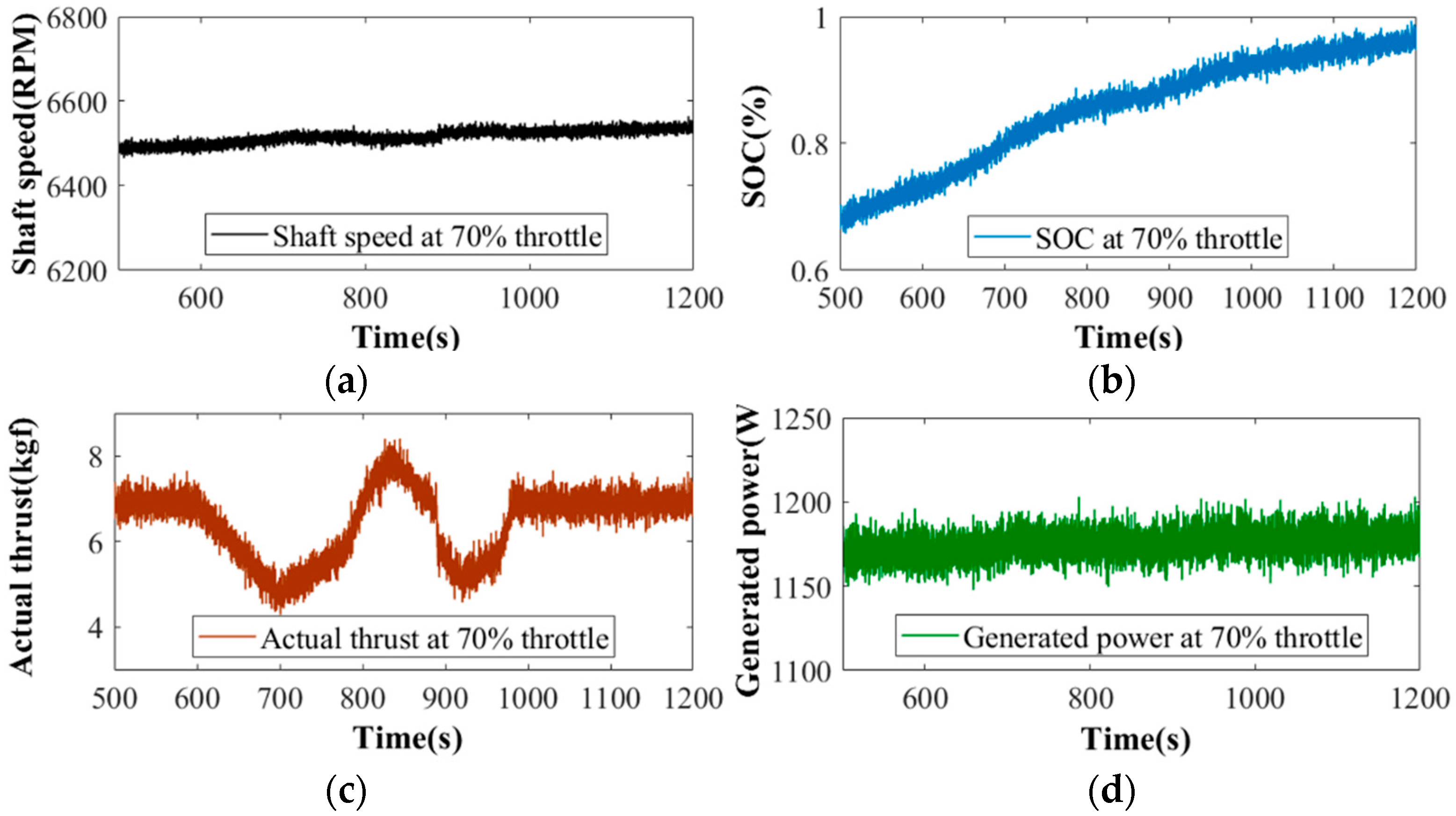
The complete hybrid power system was modelled and linearized, incorporating the states of shaft speed, voltage, and current. The shaft speed of ICE was primarily determined by the battery voltage, with a secondary influence from current. The validation of semi-fixing the shaft speed through bench testing further confirmed this relationship.
(2)
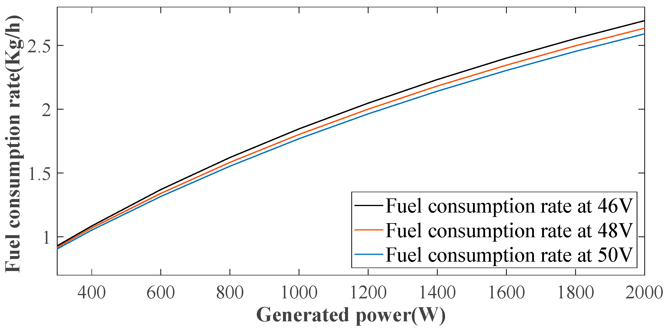
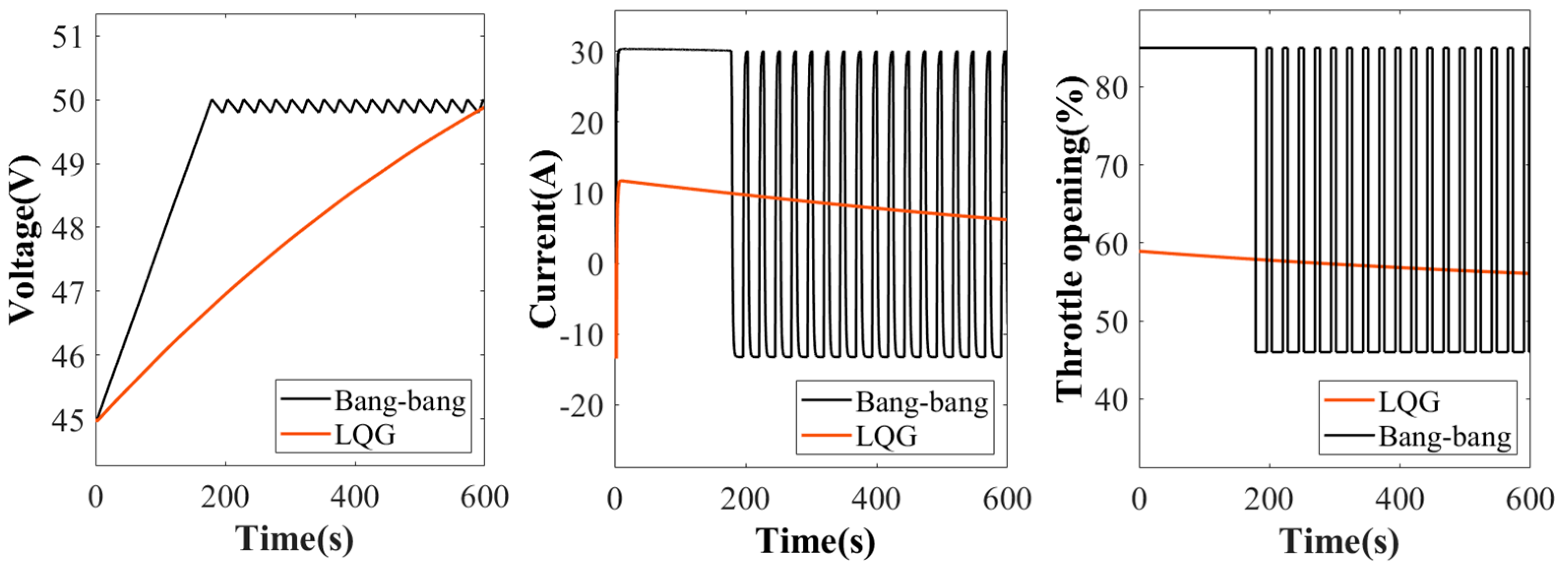
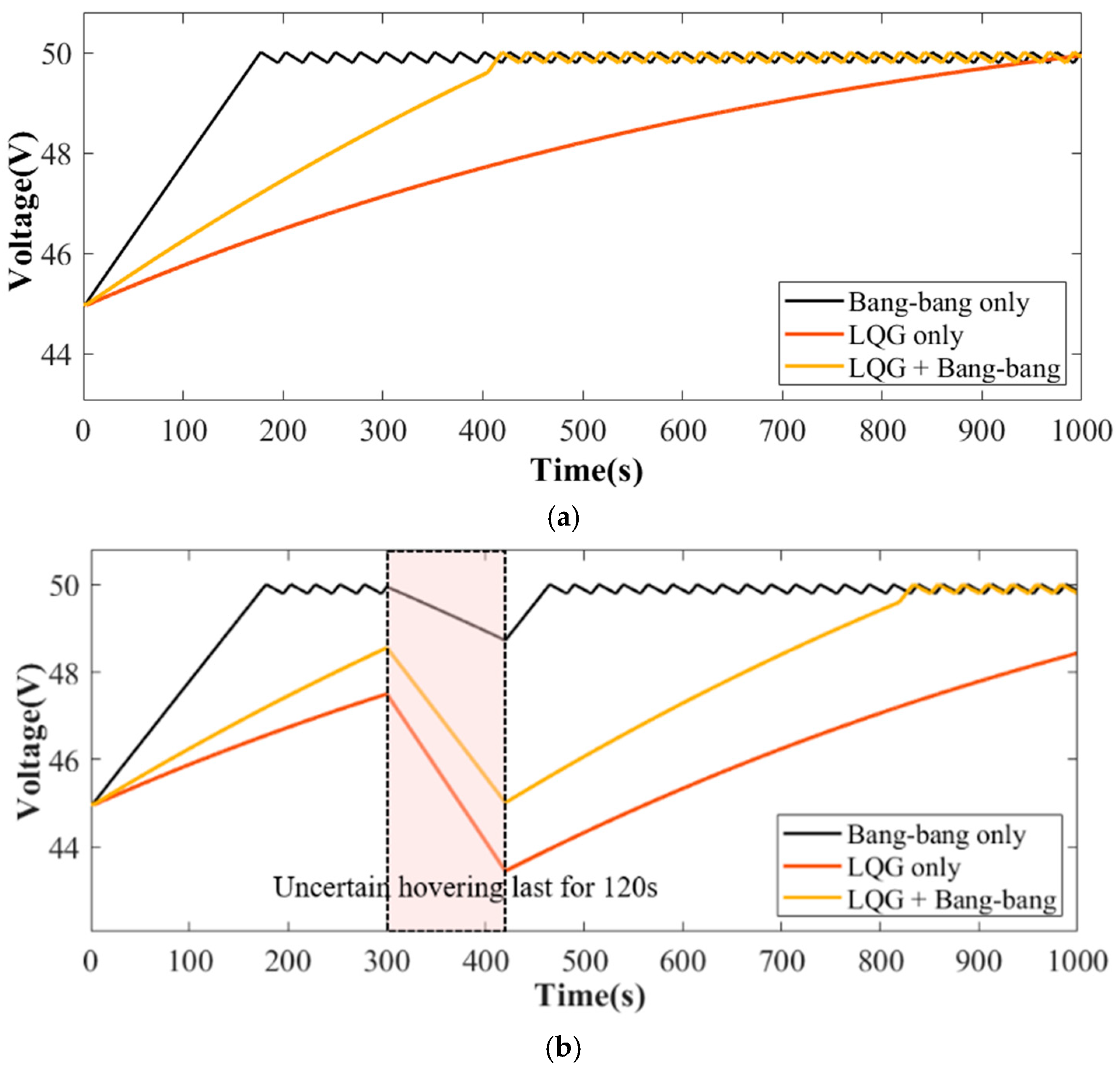
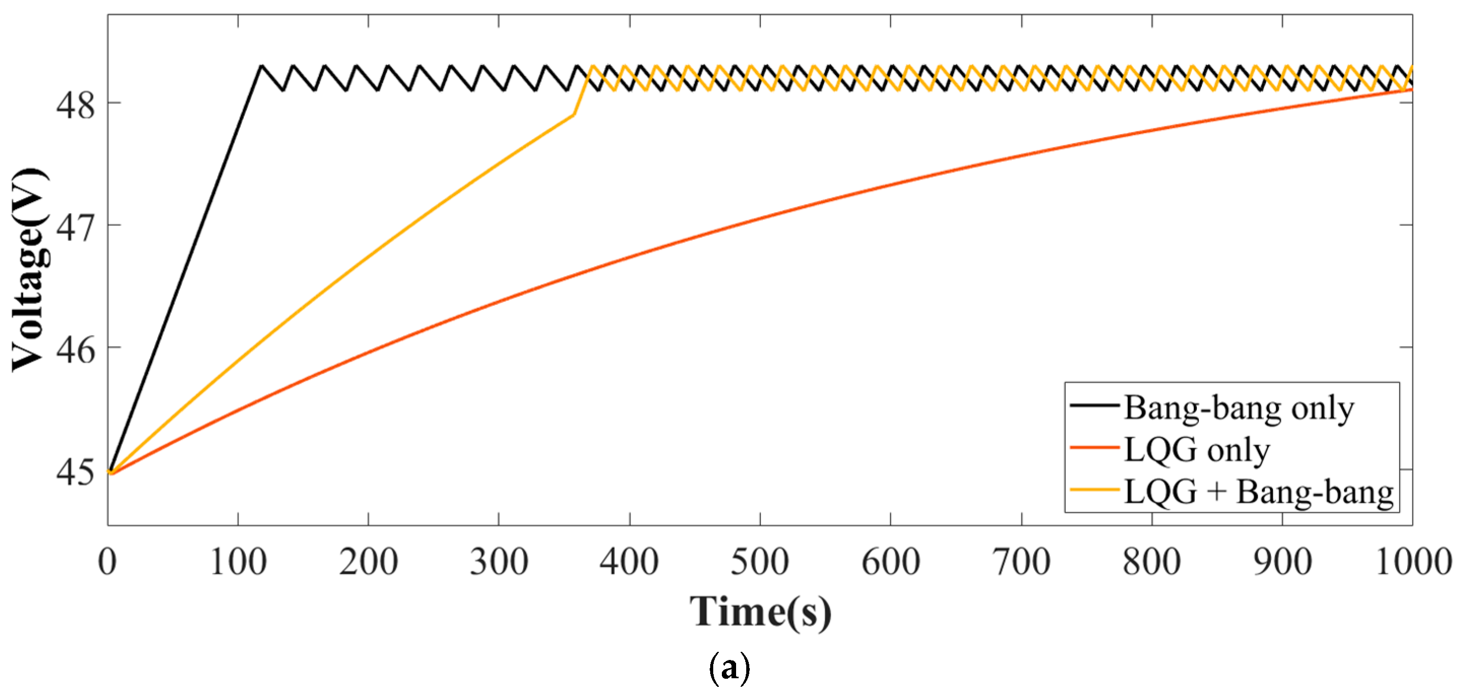
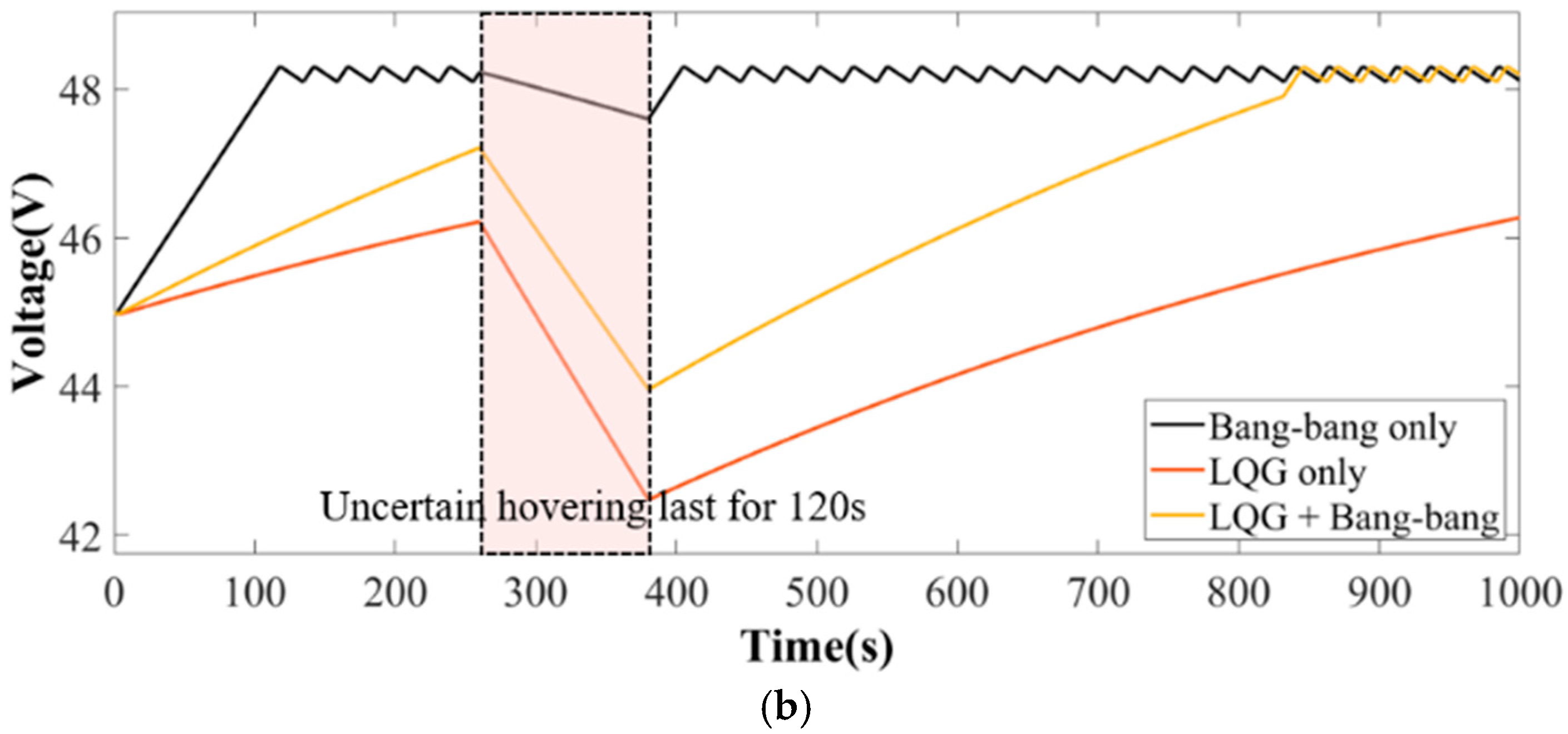
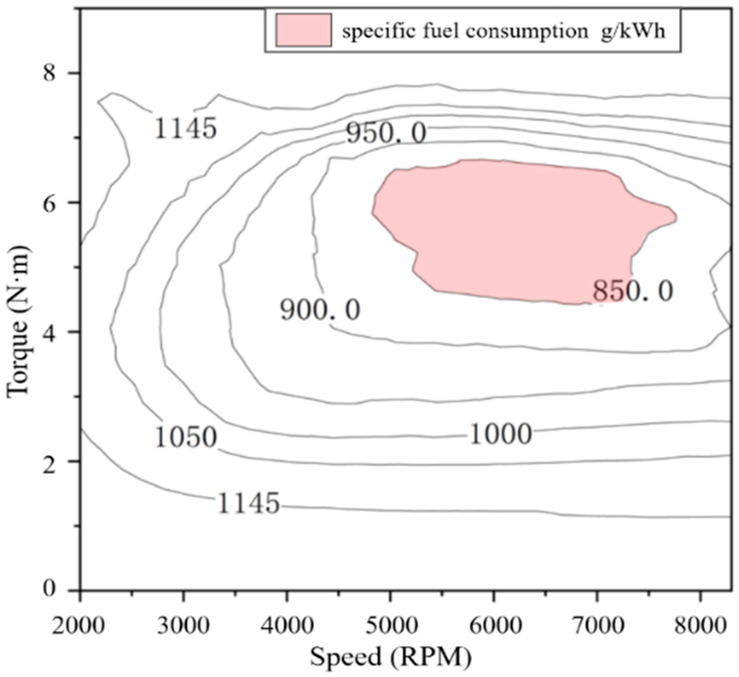
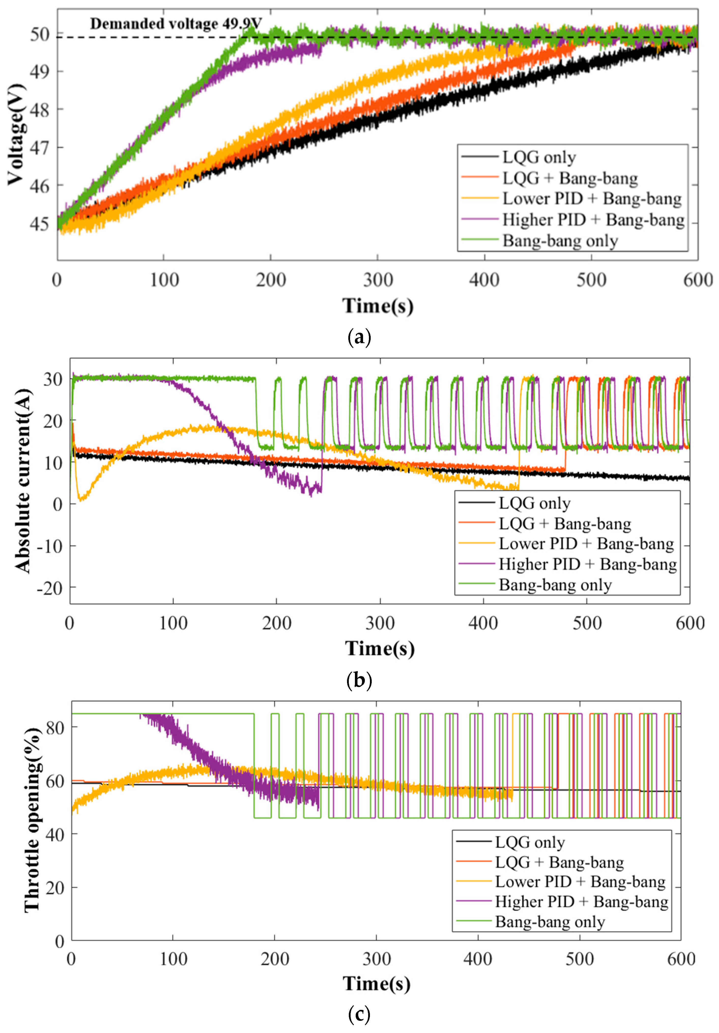
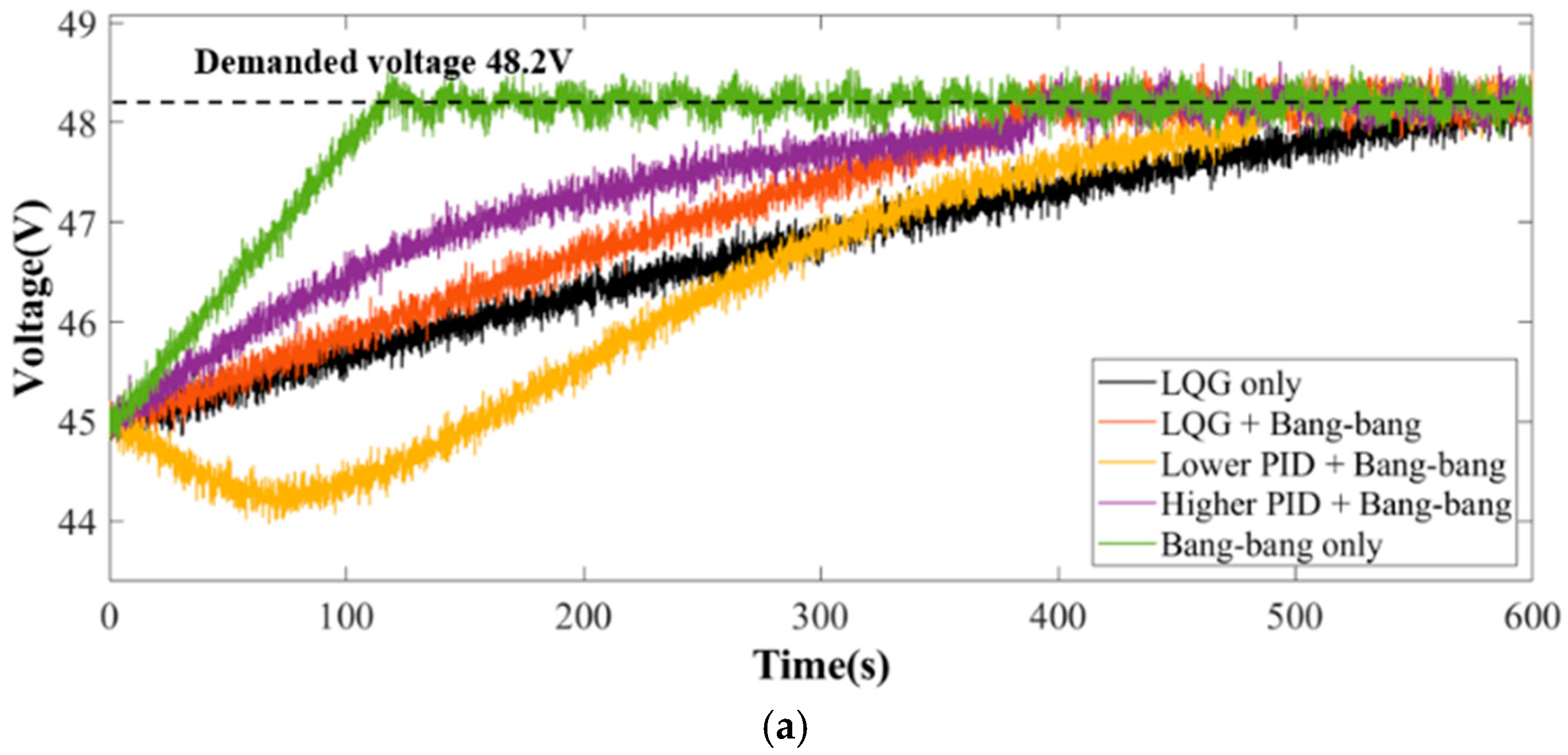
The fuel consumption chart and battery pack degradation mechanism were provided. The simulation results revealed that the LQG regulation strategy exhibits lower fuel consumption, while the bang–bang regulation strategy performed well in dealing with flight uncertainty. To strike a balance between cost and flight uncertainty, a composite power management strategy combining LQG and bang–bang regulation was devised.
(3)
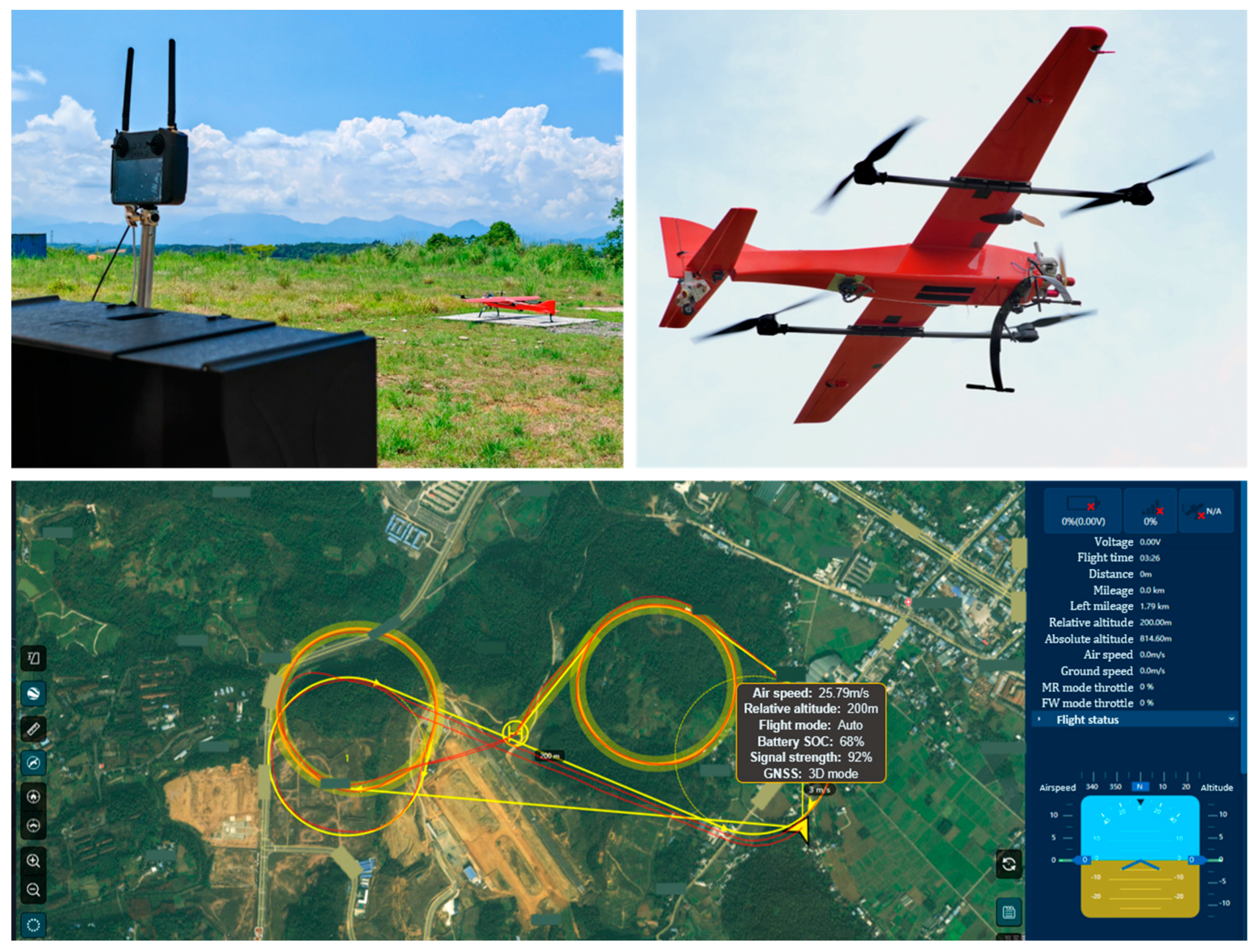
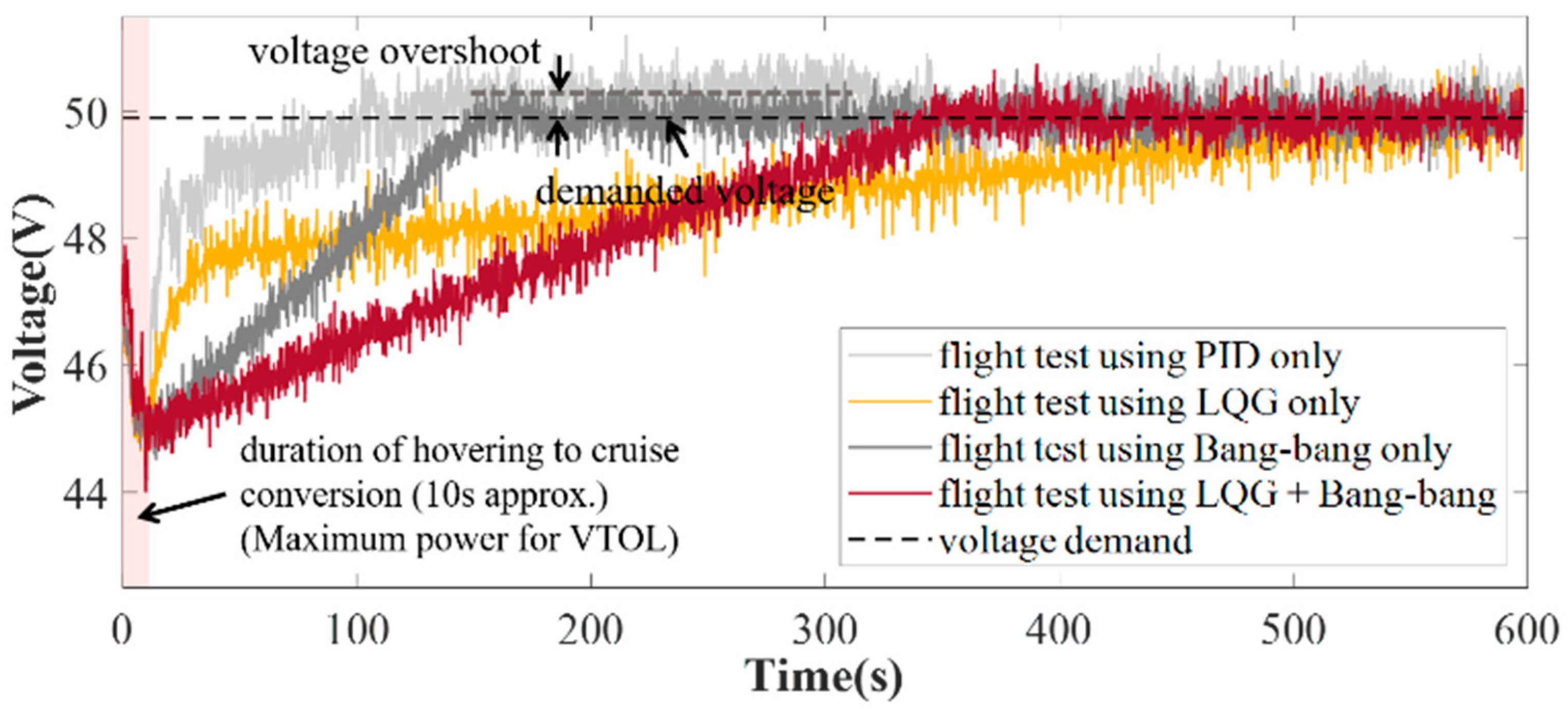
The proposed composite strategy, integrating LQG and bang–bang regulation, has been validated in both ground testing and flight tests on VTOL prototypes, demonstrating its feasibility and cost-effectiveness. In a comprehensive flight duration of 600 s with uncertainty, this strategy achieved a fuel consumption of 0.310 L, representing a 6.63% reduction compared to the LQG only strategy, which consumed 0.332 L. Battery degradation was reduced to 0.92%, indicating improved battery longevity. This composite strategy not only minimized costs but also enabled the system to achieve desired performance objectives more rapidly.
Furthermore, the absence of future research directions in the conclusion merits attention. First, optimizing the power management strategy for various flight phases, including takeoff, landing, sharp maneuvers, sharp climbing, and flight mode transformation could enhance its overall applicability. Second, integrating advanced battery monitoring techniques to more accurately assess battery health and optimize charging and discharging patterns would be beneficial. Additionally, exploring the influence of external factors such as varying weather conditions on the hybrid power system and refining the strategy accordingly could yield significant improvements. Finally, investigating the scalability of this strategy for larger-sized aircraft or fleets of VTOLs would broaden its practical applications.

Author Contributions

S.A.: Software; methodology; writing—original draft and review & editing, X.P.: Funding acquisition; project administration; resources, Y.G.: Writing—review & editing; validation. J.Y.: Visualization, G.X.: Supervision; investigation. S.D.: Conceptualization; funding acquisition and resources. All authors have read and agreed to the published version of the manuscript.

Funding

This work research was funded in part by Sichuan flight engineering technology research center project under grant GY2024-014C and CAFUC science foundation under grants J2023-022, J2023-023 and CZKY2024031.

Data Availability Statement

The original contributions presented in the study are included in the article, further inquiries can be directed to the corresponding author.

Conflicts of Interest

The authors declare no conflict of interest.

References

  1. Akhter, M.Z.; Raza, M.; Iftikhar, S.H. Temporal and Economic Benefits of Vertical Take-Off and Landing Vehicles in Urban Transport. In Proceedings of the 2020 Advances in Science and Engineering Technology International Conferences (ASET), Dubai, United Arab Emirates, 4 February–9 April 2020; pp. 1–6. [Google Scholar] [CrossRef]
  2. Arshad, A.; Kallungal, A.J.; Elmenshawy, A.A.A.E. Stability Analysis for a Concept Design of Vertical Take-off and Landing (VTOL) Unmanned Aerial Vehicle (UAV). In Proceedings of the 2021 International Conference on Military Technologies (ICMT), Brno, Czech Republic, 8–11 June 2021; pp. 1–6. [Google Scholar] [CrossRef]
  3. Yolcu, S.; Akdağ, M. Conceptual Design of a Cargo UAV That Can Take-off and Land Vertically. In Proceedings of the 2021 3rd International Congress on Human-Computer Interaction, Optimization and Robotic Applications (HORA), Ankara, Turkey, 11–13 June 2021; pp. 1–6. [Google Scholar] [CrossRef]
  4. Li, W.; Liang, L.; Liu, W.; Wu, X. State of Charge Estimation of Lithium-Ion Batteries Using a Discrete-Time Nonlinear Observer. IEEE Trans. Ind. Electron. 2017, 64, 8557–8565. [Google Scholar] [CrossRef]
  5. Liu, Y.; Ma, R.; Pang, S.; Xu, L.; Zhao, D.; Wei, J.; Huangfu, Y.; Gao, F. A Nonlinear Observer SOC Estimation Method Based on Electrochemical Model for Lithium-Ion Battery. IEEE Trans. Ind. Appl. 2021, 57, 1094–1104. [Google Scholar] [CrossRef]
  6. Yu, L.; Zhang, Z.; Bian, Z.; Gerada, D.; Gerada, C. Dual-Pulse Mode Control of a High-Speed Doubly Salient Electromagnetic Machine for Loss Reduction and Speed Range Extension. IEEE Trans. Ind. Electron. 2020, 67, 4391–4401. [Google Scholar] [CrossRef]
  7. Ge, L.; Zhong, J.; Bao, C.; Song, S.; De Doncker, R.W. Continuous Rotor Position Estimation for SRM Based on Transformed Unsaturated Inductance Characteristic. IEEE Trans. Power Electron. 2022, 37, 37–41. [Google Scholar] [CrossRef]
  8. Mao, S.; Ma, C.; Jiao, N.; Liu, W. Sensorless Starting Control of the Brushless Synchronous Starter/Generator based on Flux and Parameter Estimation of the Main Exciter. IEEE Trans. Power Electron. 2023, 39, 1174–1183. [Google Scholar] [CrossRef]
  9. Xie, M.; Wang, H.; Zhang, X.; Gao, Z.; Li, W. Study on impedance characteristic of aircraft cables. In Proceedings of the 2014 17th International Conference on Electrical Machines and Systems (ICEMS), Hangzhou, China, 22–25 October 2014; IEEE: New York, NY, USA, 2015; pp. 645–650. [Google Scholar]
  10. Shan, Z.; Ding, X.; Jatskevich, J.; Tse, C.K. Synthesis of multi-input multi-output DC/DC converters without energy buffer stages. IEEE Trans. Circuits Syst. II Express Briefs 2021, 68, 712–716. [Google Scholar] [CrossRef]
  11. Qi, Y.; Li, Y.; Li, W.; Deng, H.; Tang, Y. Autonomous Control of Soft Open Point for Distribution Network Reliability Enhancement. IEEE J. Emerg. Sel. Top. Power Electron. 2023, 11, 3127–3137. [Google Scholar] [CrossRef]
  12. Deng, F.; Li, Y.; Li, X.; Yao, W.; Mattavelli, P.; Zhang, X. A Decentralized Impedance Reshaping Strategy for Balanced, Unbalanced and Harmonic Power Sharing in Islanded Resistive Microgrids. IEEE Trans. Sustain. Energy 2021, 13, 743–754. [Google Scholar] [CrossRef]
  13. Chen, J.; Wang, C.; Chen, J. Investigation on the Selection of Electric Power System Architecture for Future More Electric Aircraft. IEEE Trans. Transp. Electrif. 2018, 4, 563–576. [Google Scholar] [CrossRef]
  14. Yang, Z.; Qu, J.; Ma, Y.; Shi, X. Modeling and simulation of power distribution system in more electric aircraft. J. Electr. Comput. Eng. 2015, 2015, 847624. [Google Scholar] [CrossRef]
  15. Dehesa, D.A.; Menon, S.K.; Monju, M.J. Modeling and Testing of Control Logic Approaches for Series Hybrid-Electric Powertrains for Unmanned Aerial Systems. In Proceedings of the AIAA Propulsion and Energy 2020 Forum, Online, 24–26 August 2020; p. 3961. [Google Scholar]
  16. Hageman, M.D.; McLaughlin, T.E. Considerations for pairing the ic engine and electric motor in a hybrid power system for small uavs. In Proceedings of the 2018 AIAA Aerospace Sciences Meeting, Kissimmee, FL, USA, 8–12 January, 2018; p. 2132. [Google Scholar]
  17. Tao, L.; Zhou, Y.; Zicun, L.; Zhang, X. State of art on energy management strategy for hybrid-powered unmanned aerial vehicle. Chin. J. Aeronaut. 2019, 32, 1488–1503. [Google Scholar]
  18. Campagna, N.; Castiglia, V.; Damiano, A.; Di Noia, L.P.; Miceli, R.; Di Tommaso, A.O. A hybrid energy storage sizing for a vertical take-off and landing electric aircraft. In Proceedings of the IECON 2021–47th Annual Conference of the IEEE Industrial Electronics Society, Toronto, ON, Canada, 13–16 October 2021; IEEE: New York, NY, USA, 2021; pp. 1–6. [Google Scholar]
  19. Maraschi, L.; Bernabei, L.; Marzioli, P.; Galassi, R.M.; Ciottoli, P.P.; Valorani, M.; Piergentili, F. Hybrid-electric propulsive systems sizing and performance evaluation tool for aircraft and UAV. In Proceedings of the 2022 IEEE 9th International Workshop on Metrology for AeroSpace (MetroAeroSpace), Pisa, Italy, 27–29 June 2022; IEEE: New York, NY, USA, 2022; pp. 43–48. [Google Scholar]
  20. Martinez-Heredia, J.M.; Colodro, F.; Mora-Jiménez, J.L.; Remujo, A.; Soriano, J.; Esteban, S. Development of GaN technology-based DC/DC converter for hybrid UAV. IEEE Access 2020, 8, 88014–88025. [Google Scholar] [CrossRef]
  21. Bayrak, Z.U.; Kaya, U.; Oksuztepe, E. Investigation of PEMFC performance for cruising hybrid powered fixed-wing electric UAV in different temperatures. Int. J. Hydrogen Energy 2020, 45, 7036–7045. [Google Scholar] [CrossRef]
  22. van Nguyen, C.; van Quyen, T.; Le, A.M.; Truong, L.H.; Nguyen, M.T. Advanced hybrid energy harvesting systems for unmanned aerial vehicles (UAVs). Adv. Sci. Technol. Eng. Syst. J. 2020, 5, 34–39. [Google Scholar] [CrossRef]
  23. Yang, X.; Pei, X. Hybrid system for powering unmanned aerial vehicles: Demonstration and study cases. In Hybrid Technologies for Power Generation; Academic Press: Cambridge, MA, USA, 2022; pp. 439–473. [Google Scholar]
  24. Zong, J.; Zhu, B.; Hou, Z.; Yang, X.; Zhai, J. Evaluation and comparison of hybrid wing VTOL UAV with four different electric propulsion systems. Aerospace 2021, 8, 256. [Google Scholar] [CrossRef]
  25. Burgess, J.; Runnels, T.; Johnsen, J.; Drake, J.; Rouser, K. Experimental comparison of direct and active throttle control of a 7-kw turboelectric power system for unmanned aircraft. Appl. Sci. 2021, 11, 10608. [Google Scholar] [CrossRef]
  26. Hu, C.M.; Yan, D.Y.; Liu, N.; Song, X. Comparison and Simulation Research on Energy Management Strategies of Oil–Electric Hybrid Unmanned Aerial Vehicle. Chin. Intern. Combust. Engine Eng. 2022, 43, 74–83. [Google Scholar]
  27. He, C.; Tong, Y.; Xia, X.; Chen, G. Integrated optimization of energy management strategy and mission path for hybrid-electric VTOL UAVs in cargo transportation. Acta Aeronaut. Astronaut. Sin. 2024, 45, 229606. [Google Scholar]
  28. Wu, F.; Wu, Z.; Xu, J.; Hao, Q. Rule-based Transient Power Control Strategy for Hybrid System in Unmanned Aerial Vehicle. In Proceedings of the 2021 24th International Conference on Electrical Machines and Systems (ICEMS), Gyeongju, Republic of Korea, 31 October–3 November 2021; pp. 2425–2429. [Google Scholar]
  29. Tao, L.; Wang, Y.; Jin, X.; Min, Z.; Zhang, X.; Zhang, X. An optimal fuzzy logic-based energy management strategy for a fuel Cell/Battery hybrid power unmanned aerial vehicle. Aerospace 2022, 9, 115. [Google Scholar] [CrossRef]
  30. Kittaneh, O. On the Theory of the Arrhenius-Normal Model with Applications to the Life Distribution of Lithium-Ion Batteries. Batteries 2023, 9, 55. [Google Scholar] [CrossRef]
Figure 1. General view of the VTOL, powered by the proposed electro-gasoline hybrid power system.
Energies 18 00799 g001
Figure 2. Architecture of proposed direct-connected hybrid power system on the VTOL.
Energies 18 00799 g002
Figure 3. Fuel consumption rate at different voltages.
Energies 18 00799 g003
Figure 4. Schematic of power management strategy.
Energies 18 00799 g004
Figure 5. The simulation of bang–bang and LQG strategies.
Energies 18 00799 g005
Figure 6. A typical level flight profile simulation (45.0–49.9 V). (a) Ideal level flight with charging, (b) Uncertain power demand happens during level flight.
Energies 18 00799 g006
Figure 7. A typical level flight profile simulation (45.0–48.2 V). (a) Ideal level flight with charging, (b) Uncertain power demand happens during level flight.
Energies 18 00799 g007aEnergies 18 00799 g007b
Figure 8. The specialized testbench for the proposed hybrid power system.
Energies 18 00799 g008
Figure 9. Universal characteristic curve of ICE acquired by testbench.
Energies 18 00799 g009
Figure 10. On-wing thrust and power consumption vary with throttle.
Energies 18 00799 g010
Figure 11. Shaft speed is chained by the voltage, even though demanded power varies frequently (a) shaft speed. (b) SOC (c) actual thrust. (d) generated power.
Energies 18 00799 g011
Figure 12. A typical flight profile demonstration for test.
Energies 18 00799 g012
Figure 13. On-bench regulation comparison among five different power management strategies when the demand voltage is 49.9 V. (a) DC voltage. (b) Absolute DC current. (c) Input throttle opening.
Energies 18 00799 g013
Figure 14. On-bench regulation comparison among five different power management strategies when the demand voltage is 48.2 V. (a) DC voltage. (b) Absolute DC current. (c) Input throttle opening.
Energies 18 00799 g014aEnergies 18 00799 g014b
Figure 15. Proposed VTOL and its flight test, monitored by a ground station.
Energies 18 00799 g015
Figure 16. In-flight regulation comparison of DC voltage among four different power strategies.
Energies 18 00799 g016
Table 1. Simulation regulation performance comparison (with hovering during level flight).
Flight ProfilePower Management StrategyAdjusting Time
(45.0 V to 49.9 V)
Fuel Consumption
(1000 s)
Battery Pack Degradation
45.0–49.9 VLQG onlynone0.533 L0.73%
Bang–bang only180 s0.456 L1.60%
LQG + bang–bang820 s0.528 L1.34%
45.0–48.2 VLQG onlynone0.482 L0.68%
Bang–bang only120 s0.407 L1.44%
LQG + bang–bang840 s0.470 L1.06%
Table 2. Parameters at Typical Operation Conditions.
PerformanceValuePerformanceValue
VTOL take-off weight30 kgPower demand for level cruise flight600 W
Cruise airspeed27 m/sGenerated power
(charging)
1700 W
Total cruise thrust
(converted at ground)
8.6 kgfThrust on wings
(converted at ground)
2.8 × 2 kgf
ICE speed6500 RPM
Table 3. Parameters of 2 LQG regulators.
ParameterQSRVoltage Error (V)
LQR-1 Q 11 = 1.8 × 10 7 Q 33 = 1.0 × 10 2 Q i j = 0   i , j 1 , 3 S 11 = 1.8 × 10 7 S 33 = 1.0 × 10 2 S i j = 0   i , j 1 , 3 R 11 = 1 , R 22 = 1 × 10 4 R 33 = 1 , R 44 = 1 R 55 = 1 , R 66 = 1 R i j = 0   i j 3.06 × 10 3
LQR-2 Q 11 = 1.9 × 10 5 Q 33 = 1.0 × 10 2 Q i j = 0   i , j 1 , 3 S 11 = 1.9 × 10 5 S 33 = 1.0 × 10 2 S i j = 0   i , j 1 , 3 R 11 = 1 , R 22 = 1 × 10 4 R 33 = 1 , R 44 = 1 R 55 = 1 , R 66 = 1 R i j = 0   i j 1.04
Table 4. On-bench regulation performance comparison.
Demand
Voltage
Power Management StrategyAdjusting Time
(45.0 V to 49.9 V)
Fuel Consumption
(600 s)
Battery Pack DegradationOverall Cost ($)
49.9 VLQG only600 s0.325 L0.82%1.15
LQG + bang–bang480 s0.305 L0.84%1.15
Lower PI + bang–bang450 s0.299 L0.92%1.22
Higher PI + bang–bang260 s0.276 L1.92%2.14
Bang–bang only180 s0.266 L2.12%2.32
48.2 VLQG only600 s0.262 L0.77%1.03
LQG + bang–bang380 s0.255 L0.78%1.03
Lower PI + bang–bang500 s0.299 L0.88%1.18
Higher PI + bang–bang390 s0.276 L1.72%1.95
Bang–bang only120 s0.266 L2.01%2.22
Table 5. In-Flight Regulation Performance Comparison.
Power Management StrategyAdjusting Time (After Conversion)OvershootFuel Consumption
(600 s)
Battery Pack DegradationOverall Cost ($)
LQG only600 sNone0.332 L0.85%1.23
PID only150 s0.6 V0.378 L1.13%1.56
Bang–bang only150 snone0.267 L1.89%2.19
LQG + bang–bang330 snone0.310 L0.92%1.27
Disclaimer/Publisher’s Note: The statements, opinions and data contained in all publications are solely those of the individual author(s) and contributor(s) and not of MDPI and/or the editor(s). MDPI and/or the editor(s) disclaim responsibility for any injury to people or property resulting from any ideas, methods, instructions or products referred to in the content.

