Article

Improving Energy Efficiency in the Management of Drilling Waste from Trenchless Gas and Power Pipeline Construction Through the Implementation of Photovoltaic Panels and Circular Economy Principles

Department of Drilling and Geoengineering, Faculty of Drilling, Oil and Gas, AGH University of Krakow, 30-059 Krakow, Poland
*
Author to whom correspondence should be addressed.
Energies 2025, 18(4), 788; https://doi.org/10.3390/en18040788
Submission received: 28 November 2024 / Revised: 21 January 2025 / Accepted: 5 February 2025 / Published: 8 February 2025
(This article belongs to the Section H: Geo-Energy)

Abstract

:
The modern construction of transmission networks for transporting energy resources (e.g., crude oil, gas, hydrogen) or electricity is increasingly being carried out using trenchless technologies. Trenchless methods significantly reduce the need for extensive earthworks; however, they consequently generate substantial amounts of drilling waste. This waste consists primarily of a mixture of spent drilling fluids and drill cuttings. Due to the volume and composition of the waste, along with the rapidly increasing costs of waste disposal, the trenchless technology industry faces significant economic and environmental challenges related to circular economy principles in waste management. This article presents an analysis of trenchless construction methods for underground transmission networks, with particular emphasis on the quantity and quality of the generated drilling waste. Furthermore, research is conducted to develop a cationic flocculant based on polyvinylamine, designed to eliminate the harmful coagulants in drilling waste treatment technology. Based on the conducted studies, we propose a closed-loop waste management system for trenchless technologies. The implementation of circular economy principles, along with the integration of drilling fluid treatment systems with photovoltaic panels and energy storage units, enhances the energy efficiency of drilling waste treatment processes and aligns with global trends in the adoption of renewable energy sources (RESs).

1. Introduction

Economic development is accompanied by increased energy consumption and the depletion of natural resources. Households, offices, and industry require the supply of electricity, natural gas, as well as biogas, and, in the near future, hydrogen transportation. These are achieved through transmission networks comprising pipeline systems, which enable the transport of energy resources or the transmission of electricity using power cables, such as those connecting offshore wind farms [1,2,3,4].
These types of networks are now most commonly installed underground using trenchless technologies. Trenchless technologies are defined as a set of methods for the underground construction and rehabilitation of pipeline and cable infrastructure, involving relatively minor earthworks and linear excavation [5,6,7,8]. Various classifications of these technologies are detailed in previous studies [4,5,6,7,9,10,11,12]. A typical classification of trenchless technologies used for the construction of new pipelines is illustrated in Figure 1.
Microtunneling and HDD are trenchless methods widely employed for pipeline installation. The combination of these two methods has resulted in the development of a hybrid technology known as Direct Pipe® (DP) [10,13]. Analogous methods to microtunneling, HDD, and DP technologies include pipe jacking, pilot tubing, impact moling, pipe ramming, direct drilling, and horizontal casing drilling. However, the direct drilling and horizontal casing drilling technologies have not yet been used in Poland.
Among the aforementioned trenchless technologies, the most commonly used in Poland are microtunneling and pipe jacking. However, the distances typically achieved with these methods are significantly shorter than those with HDD or DP technologies. Generally, the pipe jacking method does not exceed a distance of 100 m, while microtunneling projects only slightly surpass 200 m. These methods are also characterized by lower drilling speeds due to the necessity of constructing launch and reception shafts. Additionally, the depths at which these works can be conducted are significantly shallower than with HDD technology, usually remaining below 5 m. Due to the requirement for constructing both the launch and reception shafts, as well as a robust concrete retaining wall, microtunneling is more expensive technology compared to HDD or DP.
Currently, when designing the trenchless installation of steel pipelines over distances exceeding several hundred meters, engineers predominantly use two construction techniques: HDD or DP® [6,14,15]. These technologies are playing a significant role in the global energy transition. For instance, between 2021 and 2024, these methods were employed in Europe for shoreline crossings to install power cables from offshore wind farms in the Baltic Sea.
The history of HDD technology dates back to the 1960s, originating with the research and development division of AT&T Bell Laboratories in the United States. Researchers at this institution were the first to develop an impact drilling rig powered by compressed air. A major project utilizing HDD was undertaken by Titan Construction, USA, in 1971, for the installation of a gas pipeline beneath the Pajero River. The initial borehole spanned 183 m [13,16,17]. The first significant HDD installation in Poland was completed in 1991 [18,19,20,21]. The longest HDD borehole in the world to date, measuring 5205 m, was drilled in the People’s Republic of China in 2018 [22].
Standard HDD technology involves three primary stages: (stage 1) pilot drilling, (stage 2) reaming, and (stage 4) pipe installation, also known as “pullback” (Figure 2) [16,23,24]. However, for large-scale installations in Poland, an additional stage—calibration (stage 3)—is implemented (Figure 2). This stage entails verifying the borehole’s integrity and assessing its readiness for pipeline installation. During calibration, it is also possible to evaluate the resistance posed by the pipeline string and the calibration tool.
Direct Pipe® is among the most recent advancements in pipeline installation technology. This method allows for the simultaneous drilling of the borehole and installation of the pipeline in a single operational step. The Direct Pipe® method was developed by the German company Herrenknecht AG, located in Schwanau, Germany, which first applied this technology to construct a water supply network beneath the Rhine River in 2007 [13,25,26]. To date, approximately 200 installations have been completed worldwide using Direct Pipe® technology, 31 of which were executed by the Polish company PPI Chrobok, now known as GGT Solution, part of the UOS Drilling SA group, based in Warsaw, Poland. The longest installation using the Direct Pipe® method involved a 48” (1219 mm) diameter pipe over a length of 2220 m [27,28]. Additionally, a Polish company completed the longest domestic installation, spanning 1400 m, using a 40” (1016 mm) diameter pipe [9].
Table 1 presents a comparative analysis of HDD and Direct Pipe® technologies alongside trenchless methods, highlighting their primary advantages, limitations, and disadvantages.
The data summarized in Table 1 indicate that trenchless technologies such as HDD and DP minimize the need for extensive earthworks, and, due to the use of modern electric or hybrid drilling machines, are perceived as environmentally friendly. However, one of the most significant environmental hazards associated with these methods is their potential negative impact on groundwater due to drilling fluid leaks and the generation of considerable amounts of drilling waste, including used drilling fluids and drill cuttings [2,29,30,31].
Drilling fluids plays a crucial role in the overall success of projects utilizing trenchless technologies, particularly in HDD operations. The basic task of drilling fluid in HDD technology is to remove the cuttings from the borehole, keep them suspended and transport them to the surface so that the drilling operation can be carried out smoothly. Additionally, in this technology, the drilling fluid is used for flushing; hydro-treating the ground; stabilizing the wall of the well; inhibiting clayey layers; cooling, lubricating and cleaning the drill head; reducing the friction of the ground against the outer surface of the pipeline during its installation; and generating rotational power in the downhole motor [6,32].
Unlike HDD technology, the drilling fluid primarily has basically two functions to perform in DP drilling. The first is to ensure that the outer surfaces of jacking pipes are properly lubricated, thus reducing the surface traction between the ground and the pipeline being jacked [33]. The drilling fluids used in DP technologies should have excellent lubricating properties and low rheological parameters, as the shear stresses that develop on the pipe during installation directly depend on the viscosity and lubricating performance of the drilling fluids [34].
Given the critical roles that drilling fluids must fulfill in the borehole during HDD and DP operations, these fluids are complex polymer–mineral dispersions characterized by diverse chemical and mineralogical-phase compositions, as well as varying proportions of colloidal solids dispersed in an aqueous medium [35,36]. Although the composition of drilling fluids may vary slightly between boreholes, observations from European markets indicate that approximately 95% of trenchless technology projects have used bentonite-based mud modified with biopolymers and polymers, as noted by Osikowicz [37] and corroborated by other researchers [38,39,40,41,42]. In these systems, bentonite serves as the solid colloidal phase. The addition of natural polymers (biopolymers) such as natural resins, starch derivatives, cellulose, tannins, and lignins, along with semi-natural polymers like PHPA, is necessary to regulate the filtration, rheological, and inhibitive properties of the drilling fluids [43,44]. Figure 3 shows the typical composition of the bentonite mud used in HDD and DP technology.
The presence of polymers in the composition of a drilling fluid induces a chemical modification of the properties of clay minerals, contributing to an increase in the stability of the drilling fluid over time. This stability is primarily attributed to the presence of clay minerals in the form of bentonite, which acts as a structuring agent, as well as the interactions between long-chain polymers and chemical additives with clay minerals [45,46,47]. The waste generated from such drilling fluids can pose a significant threat to the ground and water environment, primarily due to the presence of compounds such as [45,47,48].
-
Bentonites, which undergo sedimentation only after the degradation of the protective colloids and a decrease in pH;
-
Polymers that induce the chemical modification of the properties of clay minerals, contributing to the increased stability of the waste, with durability often exceeding several decades;
-
Organic substances with high reductive potential, which, during waste storage, release methane into the atmosphere as a result of the decomposition processes.
The emission of methane from drilling waste represents a significant environmental issue, particularly in the context of the EU’s strategy for reducing the emissions of this greenhouse gas [49]. The regulation proposed by the European Commission concerning the reduction in methane emissions in the energy sector, which includes the obligation to monitor, report, and repair methane leaks throughout the entire energy supply chain, also encompasses the emissions associated with drilling waste. Consequently, companies involved in generating drilling waste will be required to implement measures aimed at minimizing the methane emissions from such waste.
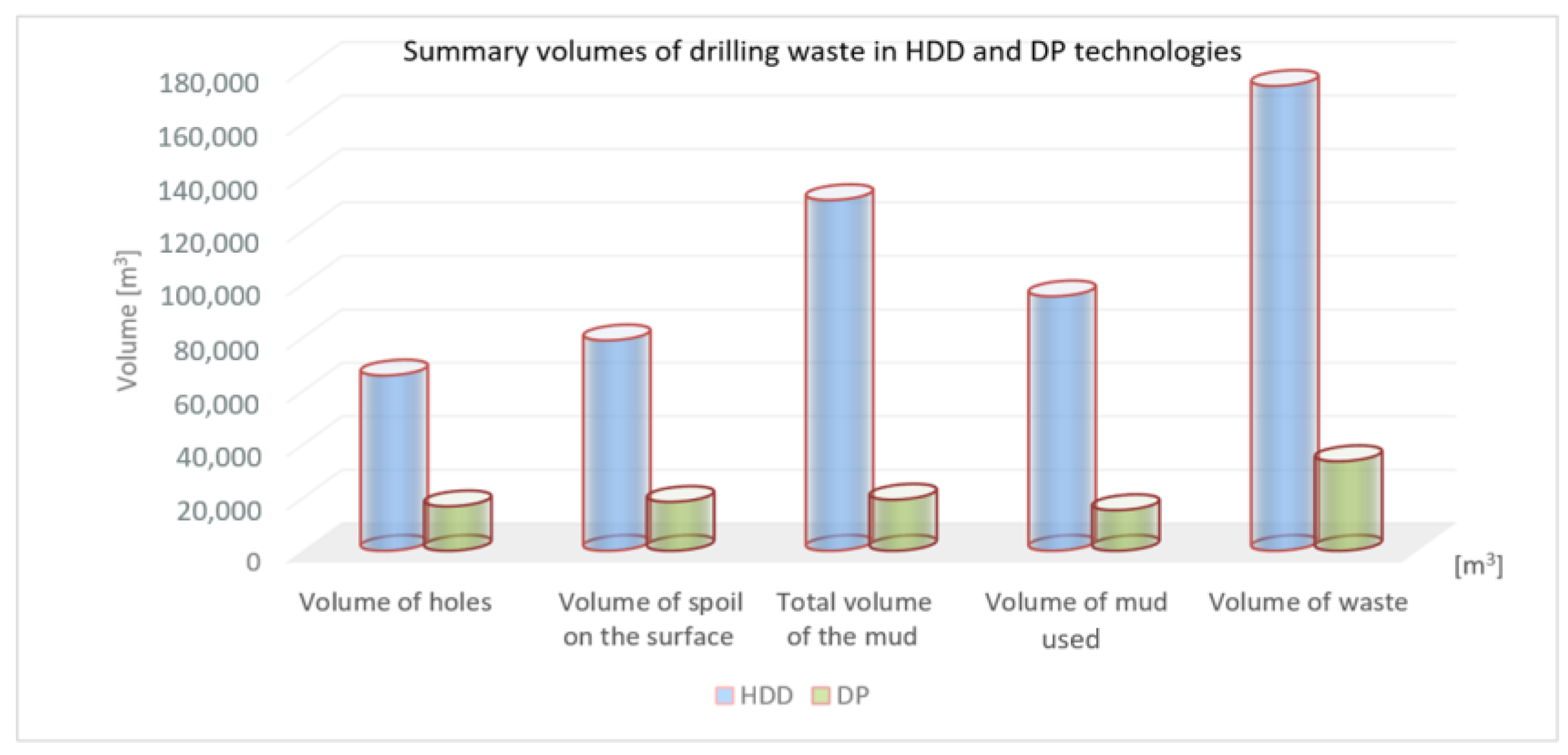
An additional challenge in managing the drilling waste produced during HDD and DP drilling technologies is the significant volume of waste generated in the form of sludgy colloidal hydrosol [30,31]. The estimated amounts of waste, calculated based on data [50] obtained from 100 HDD and 31 Direct Pipe® projects in Poland, are summarized in Figure 4. When estimating the amount of generated waste, the standard diameters of the drilled crossings were also considered for a given pipe diameter and technology. The borehole cavity formation factor and the efficiency of drilling fluid treatment systems were additionally considered. The total length of the analyzed crossings executed using HDD and DP® technologies was 83.5 km.
An analysis of the data presented in Figure 4 demonstrates that the volume of drilling fluid, as well as the quantity and quality of drilling waste, primarily depends on the type of technology used—DP or HDD. Due to the characteristics of DP technology, namely, the possibility of a single-stage operation, the final bore diameter for the installation of a DN 1000 pipe is typically 1140 mm, whereas, in a comparable case using HDD technology, the bore diameter is approximately 1321 mm. This results in a significantly larger nominal volume of excavated material. It is widely recognized that the DP method requires less drilling fluid material. However, it should be emphasized that due to the use of pumps for circulating the drilling fluids in the DP method, it is sometimes necessary to replace the entire volume of fluid.
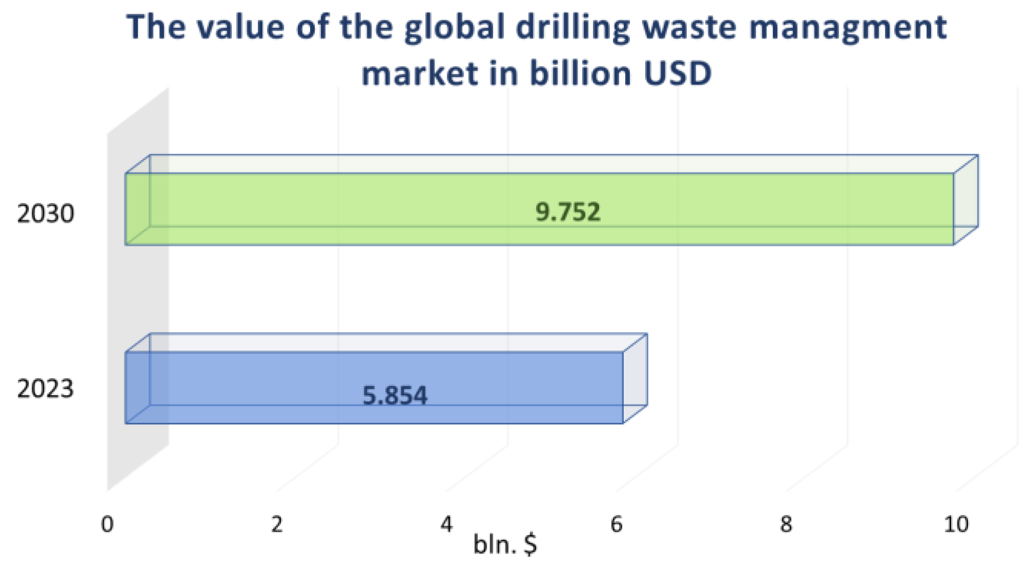
The volume and quality of drilling waste, coupled with increasingly stringent environmental regulations [51,52,53,54,55,56,57], are pushing the trenchless technology industry to address the significant ecological and economic challenges associated with the disposal and management of such waste [58]. In the coming years, the costs of waste disposal and management are expected to increase. According to a report by 360iResearch published in September 2024 [59], the value of the global drilling waste management market will significantly increase from a predicted value of USD 5.85 billion in 2023 to USD 9.75 billion by 2030 (Figure 5).
Given the above considerations and recognizing that the electricity and drilling fluid production costs in trenchless technologies constitute a significant portion of the project budget, it is essential to develop an energy-efficient and environmentally friendly system for managing drilling waste. Improving the energy efficiency of the drilling waste management process requires not only implementing circular economy principles (material recovery and processing of drilling waste) but also addressing logistical aspects, monitoring and optimizing drilling fluid treatment systems, and incorporating renewable energy sources to power these systems. Figure 6 illustrates the key strategies for enhancing energy efficiency in the management of the drilling waste generated by trenchless technologies.
Enhancing the energy efficiency of drilling waste management processes can provide companies involved in trenchless technologies with significant economic benefits and improved market competitiveness through
-
A reduction in electricity costs;
-
Decreased operational costs associated with the reuse of drilling fluids and mineral resources;
-
A reduction in the expenses related to the transportation of waste to disposal sites and fees for landfilling.
The concept for managing the waste generated by trenchless technologies, as proposed by the authors, aligns with the 2030 Agenda for Sustainable Development [60]. According to this agenda [60] and the Sustainable Development Goals [61], an essential component of ecological security involves ensuring sustainable patterns of consumption and production, particularly in the energy sector. To achieve these objectives, the environmentally friendly management of chemicals and all types of waste throughout their life cycle must be implemented in accordance with established international frameworks. The release of such substances into the air, water, and ground should be significantly reduced, especially greenhouse gas emissions in the form of methane. This would minimize their negative impact on human health and the environment. Moreover, by 2030, the level of waste generation should be significantly reduced through prevention, reduction, recycling, and reuse [60,61].
Globally, a wide range of methods for managing drilling waste are available [35,62,63,64,65,66], among which the most commonly used are stabilization/solidification [62,63], landfilling [62], reinjection [63], chemical processes that reduce waste toxicity and volume [67,68], and, in the case of hydrocarbon-contaminated waste, bioremediation [48] and thermomechanical cutting cleaning [69]. However, these solutions were primarily designed for the management and disposal of drilling waste generated during hydrocarbon exploration. The implementation of these methods in the trenchless technology sector is often impossible or associated with numerous environmental and technological challenges. The primary issue with applying waste disposal technologies for drilling waste is the volume of waste generated by trenchless technologies. The amount of waste produced in HDD and DP technologies can be up to ten times greater than that generated during vertical drilling for oil or natural gas. Additionally, trenchless drilling is often conducted in highly urbanized areas, where the space for setting up drilling waste disposal equipment is limited. Moreover, the sustainable development of trenchless technologies and the increasingly stringent environmental regulations—especially when drilling near rivers or coastal areas—necessitate the use of environmentally friendly chemical reagents. To address this, we propose improvements in the energy efficiency of drilling waste management processes and the elimination of harmful coagulants from the methods of disposing drilling waste. To achieve this, environmentally friendly flocculants based on poly(N-vinylamines) were developed. Currently, the flocculants used in drilling fluid technologies are predominantly acrylic polymers. The most notable representative of this group is partially hydrolyzed polyacrylamide (PHPA), characterized by exceptionally high molecular weights (exceeding 1 million atomic mass units). The PHPA structure contains approximately 30% carboxyl groups. As an anionic polymer, it requires the addition of supplementary chemical agents—coagulants—to operate effectively in bentonite-based drilling fluids. Coagulants typically include strong electrolytes containing multivalent metal ions, derived from water-soluble inorganic salts such as FeCl3, Fe2(SO4)3, FeSO4, CaCl2, Al2(SO4)3, and AlCl3, as well as aluminum alums and hydroxy-aluminum or hydroxy-iron complexes [70]. During the flocculation process, coagulants are introduced first. Their cations adsorb onto the negatively charged surfaces of the solid particles in waste drilling fluids, altering their surface charge (Stern–Helmholtz double layer). This step enables the subsequent addition of an anionic flocculant, allowing it to act effectively.
Even so, this method does not fully address the challenges. PHPA polymers, with their anionic carboxyl groups, are highly sensitive to inorganic salt cations and are susceptible to degradation, particularly in the presence of multivalent ions. Consequently, the ion content in the drilling fluid must be meticulously controlled to ensure the correct amount of coagulant is added, thereby preventing the precipitation of the flocculant. Furthermore, the acrylic flocculants used in drilling operations are polymers with extremely high molecular weights, which hinder their movement within drilling waste characterized by high rheological properties and a significant solid-phase content. As a result, flocculation often proceeds very slowly or occurs only locally. Moreover, the need to use coagulants alongside anionic flocculants increases the cost of drilling waste disposal and leads to further contamination by salt ions, thus escalating the expenses associated with waste management.
A potential solution to these challenges may be the use of cationic polymers. However, the most of these polymers are ineffective in alkaline drilling fluids, possess excessive steric hindrance that prevents effective adsorption on solid-phase particles, or are prohibitively expensive. The authors propose addressing these issues by using cationic polymers—copolymers of N-vinylamine—as effective flocculants for phase separation in the context of drilling waste management. Through the application of N-vinylamine copolymers, along with the proposed technology for managing the drilling waste generated in HDD and DP operations, the system aims to minimize both the environmental impact and the volume of waste. Furthermore, the proposed technology will contribute to reducing CO2 emissions by eliminating the need to transport waste to landfilling sites. It will also decrease the consumption of mineral resources by implementing a closed-loop drilling fluid system. Additionally, integrating photovoltaic panels into the proposed system will significantly improve the energy efficiency of the entire process.
The proposed concept for managing the drilling waste generated during trenchless operations aims to enhance the perception of these methods as even more environmentally friendly, aligning with circular economy trends. According to the authors, the proposed drilling waste management system, incorporating photovoltaic panels and eliminating the need for waste landfilling and transportation to disposal sites, supports sustainable development, improves energy efficiency, and contributes to the efforts aimed at reducing greenhouse gas emissions (CO2 and CH4).

2. Material and Methods

2.1. Materials

The research material consisted of drilling waste containing drill cuttings and used spent drilling mud, categorized into bentonite-based, bentonite-polymer (inhibited) types. The waste samples were collected from various regions in Poland where HDD and DP technologies were employed. Since clay formations dominate the geological profiles of many areas in Poland, the drilling mud systems predominantly utilized dual inhibition mechanisms. The bentonite drilling fluids were inhibited using a polymer-based clay inhibitor, commercially known as ClayCutter (CETCO, Hoffman Estates, IL, USA), which is based on PHPA and potassium ions, and HydroClay (CETCO, Hoffman Estates, IL, USA), a product based on modified gypsum that supplies calcium ions to the system. To increase the pH, soda ash was also added to the drilling mud.

2.2. Polymer Synthesis

The direct synthesis of N-vinylamine polymers is not feasible because the N-vinylamine monomer is unstable and does not exist freely under natural conditions. Therefore, the polymer synthesis was carried out in two stages. In the first stage, poly(N-vinylformamide) was synthesized via free radical polymerization [71]. In the second stage, the controlled partial hydrolysis of the synthesized polymer was conducted resulting in two copolymers, poly(N-vinylformamide-co-N-vinylamine), differing in the proportion of cationic groups in their chains: the polymer designated as PAm-25 contained 25% ionic groups, while the polymer PAm-50 contained 50% ionic groups.
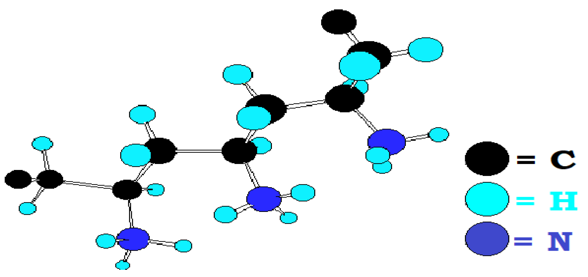
The synthesized vinylamine polymers exhibit very low steric hindrance, as the primary amine groups are directly attached to the main chain and carry a relatively high positive charge (Figure 7). The average molecular weights of the synthesized polymers do not exceed 200,000 atomic mass units.

2.3. Mixing Spent Drilling Mud with Flocculants

For a sample of drilling waste (used drilling mud) with a volume of 1000 cm3, an amount of synthesized flocculant ranging from 0.1 to 0.75 g/cm3 was added. The mixture was stirred for 15 s using a four-blade stirrer. The length and width of each blade were 25 mm and 15 mm, respectively. The stirrer operated at a rotational speed of 2500 rpm. The mixture was then transferred to a graduated cylinder with a capacity of 1000 cm3. Using a stopwatch, the settling time of the flocs was measured over a specified section of the graduated cylinder.

2.4. Research Methodology

The measurement of the physicochemical properties of the analyzed drilling waste mud was conducted in accordance with the PN-EN ISO 10414 standard [72] and the technical standard ST-IGG-3301:2021 [73].
The selection of a rheological model was performed using a proprietary software program, Rheosolution 3.01, developed at the Department of Drilling and Geoengineering, Faculty of Drilling, Oil and Gas, AGH University of Science and Technology. This program enables the automation of the process for determining the optimal rheological model for drilling mud [74]. The Pearson correlation coefficient (R) was used to select the optimal rheological model. In the process of designating rheological parameters for the Bingham Plastic, Casson, Ostwald de Waele and Newtonian models, applying a linear regression method was proposed. In the case of the Herschel–Bulkley, Vom Berg, and Hahn–Eyring models, applying a nonlinear regression method was suggested [74].
The microstructure analysis of the examined drilling waste mud was conducted using a scanning electron microscope (FEI Quanta 200 FEG SEM) equipped with a micro-area chemical composition analyzer.
X-ray qualitative analyses of the mineral composition were carried out using the Debye–Sherrer powder method. X-ray patterns were recorded with an APD X’Pert PW 3020 (Philips) diffractometer under the following operational conditions: CuKα radiation, graphite reflection monochromator, voltage 35 kV, lamp current 30 mA, step recording with a step of 0.05 o2θ, and counting time 1 sec/step. The positions of the X-ray reflections recalculated into the d interplanar values were used for the identification of the crystalline mineral phases on the basis of the ICDD (International Centre for Diffraction Data) catalogue and XRAYAN software, version 4.0.1.
For scanning microscopy and microstructural analysis, SEM-EDS, and X-ray diffractometry (XRD), all samples spent drilling mud were prepared in the same way. A dry mass sample of each waste drilling mud with a weight of about 30 g was obtained by slow drying (evaporation of H2O) at 105 °C for 24 h.
The suitability of the synthesized polymers for flocculating drilling waste mud was evaluated by measuring the time required for the water/floc boundary to move through a specified section of the measuring cylinder. Following the measurement of the flocculation time, the flocculation coefficient (k) was determined. This coefficient represents the ratio expressing how many times flocculation using the flocculant is faster compared to flocculation without it:
k = t 0 t f
where t0 is the flocculation time without the flocculant [s]; tf is the flocculation time with the flocculant [s].
Since drilling mud is a stable suspension over time, determining t0 can be prolonged or even impossible. For the purposes of this test, a fixed value of t0 = 86,400 s (24 h) was adopted for all measurements. The next step involved plotting the relationship between the flocculation coefficient and the polymer dose. The amount of flocculant is expressed in kg/m3 of waste drilling mud, facilitating the transition from laboratory scale to industrial scale and allowing for the calculation of the cost of applying the given flocculant. The optimal flocculant dose was determined based on the maximum of the regression curve.

3. Research Results

The measurements of the physicochemical properties of the analyzed spent bentonite-based drilling mud, conducted in accordance with the PN-EN ISO 10414 standard [72] and the technical standard ST-IGG-3301:2021 [73], are summarized in Table 2.
The results of the analysis of the spent bentonite-based drilling mud presented in Table 2 indicate that these muds form thixotropic aqueous dispersions with rheological parameters described by the Herschel–Bulkley equation, a model for non-Newtonian fluids. The flow behavior is associated with the formation and breakdown of mineral and mineral–polymer structures (disintegration, recombination, or conformational changes in polymer chains) (see Table 2). The plastic viscosity of these systems ranged from 6.1 to 27.5 mPas, while the yield stress, reflecting the size of the structural network, varied from 8.71 to 31.36 Pa. The structural strength measured after 10 min ranged between 9.10 and 44.00 Pa. The analyzed spent bentonite-based mud, particularly the bentonite-polymer and bentonite-inhibited variants, are highly stable polymer–mineral systems with enhanced rheological properties [75].
Capillary suction time (CST) measurements indicated that these used drilling mud formed colloidal systems with notably poor filtration properties and low permeability (the average CST value for the analyzed spent bentonite-based drilling mud was approximately 70,200 s) (see Table 2). These observations were further supported by filtration tests. Under a differential pressure ∆p = 0.7 MPa, the bentonite-based waste mud released only small quantities of liquid phase, ranging from 5.0 to 25.0 cm3over 0.5 h (Table 2).
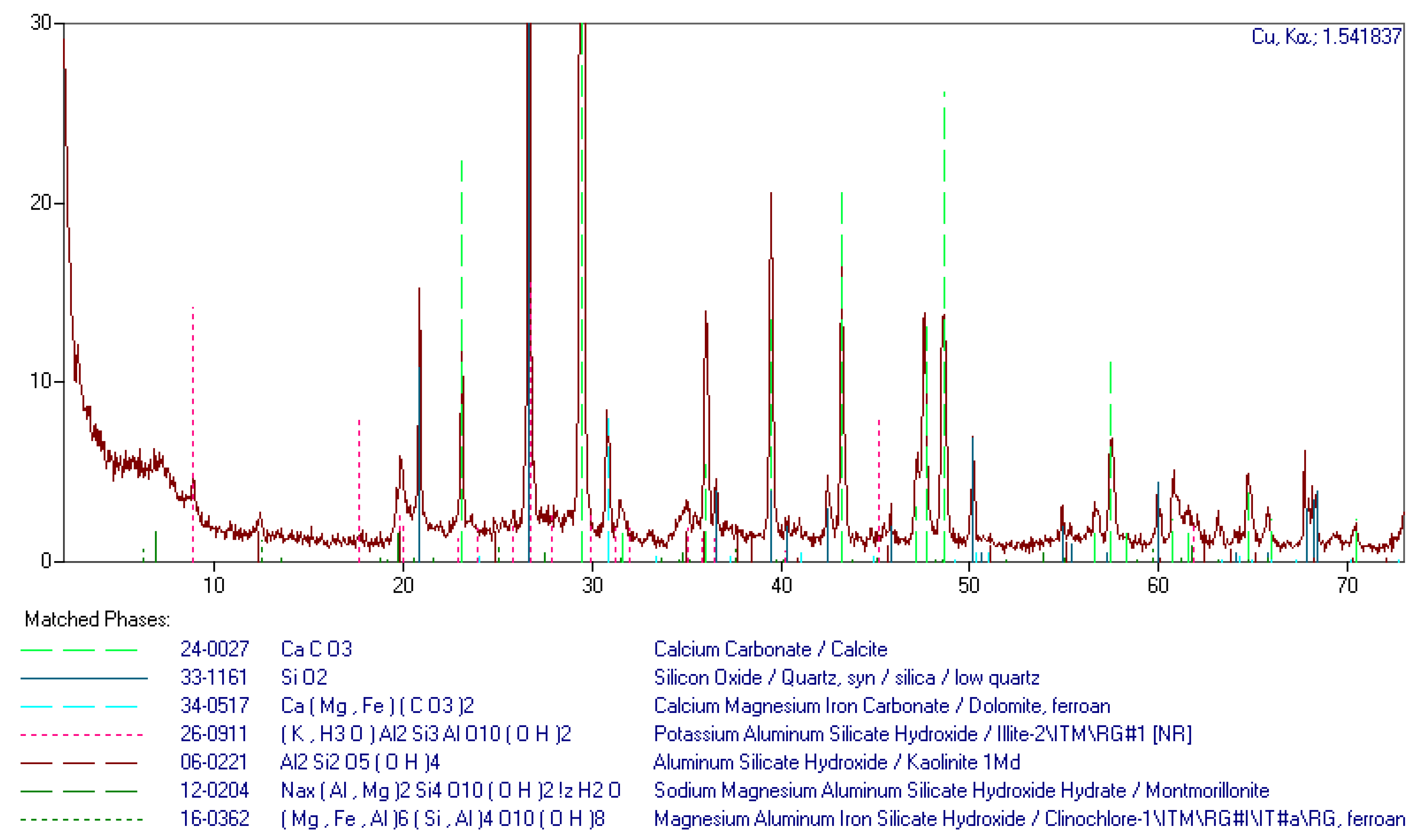
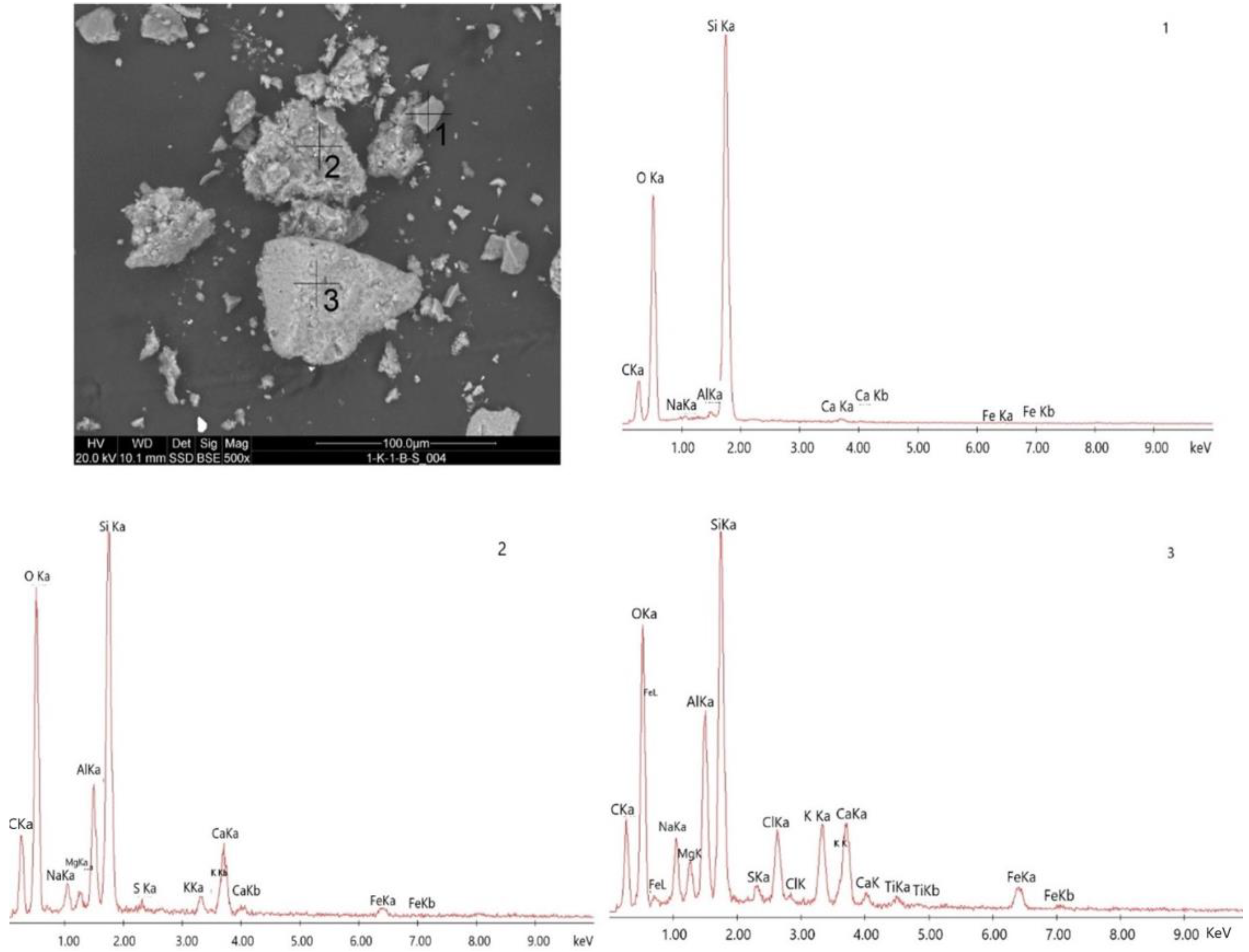
The phase composition analysis of the spent bentonite-based drilling mud, conducted using the Debye–Scherrer powder diffraction method (Figure 8, Table 3), along with microstructural analysis supported by energy-dispersive spectroscopy (EDS) (Figure 9), revealed that these wastes were predominantly composed of organic–mineral colloidal particles suspended in an aqueous dispersive phase. This phase was enriched with solid material derived from the drilled formations, including finely dispersed layered silicate minerals (illite, smectite, kaolinite), quartz, feldspars, and carbonate minerals such as calcite and dolomite.
The analysis of the X-ray diffraction patterns (Figure 8) and SEM images (Figure 9) indicates that the spent bentonite-based drilling mud contained highly dispersed, swelling clay minerals (smectites, illites, and mixed-layer smectite-illite minerals) that are enriched during drilling. These minerals complex with the hydrophilic macromolecules and organic polymers present in bentonite-based drilling fluids, forming highly stable micellar hydrogels. The resulting mineral–polymer systems, composed primarily of clay minerals and organic polymers, exhibit the ability to adsorb and absorb cations and anions, retain them, and exchange them for other ions. These properties are crucial for the minimization and management of drilling waste [75,76], as such systems are resistant to phase separation (liquid–solid separation). According to Kwas-Kotlarek [38], the finer the fraction of the drilled soil (clay, loam, sandy-clay formations), the more difficult it is to clean drilling waste mud using mechanical recycling systems. Mechanical recycling systems for drilling mud are the most effective when drilling operations are performed in sand, gravel, or solid rock fractions. The drilling mud used in clay- and clay mineral-containing soils cannot be effectively cleaned through mechanical separation alone [75,77,78,79]. They cannot be successfully centrifuged or dewatered unless subjected to preliminary treatment and destabilization using chemical methods, such as coagulation and flocculation.
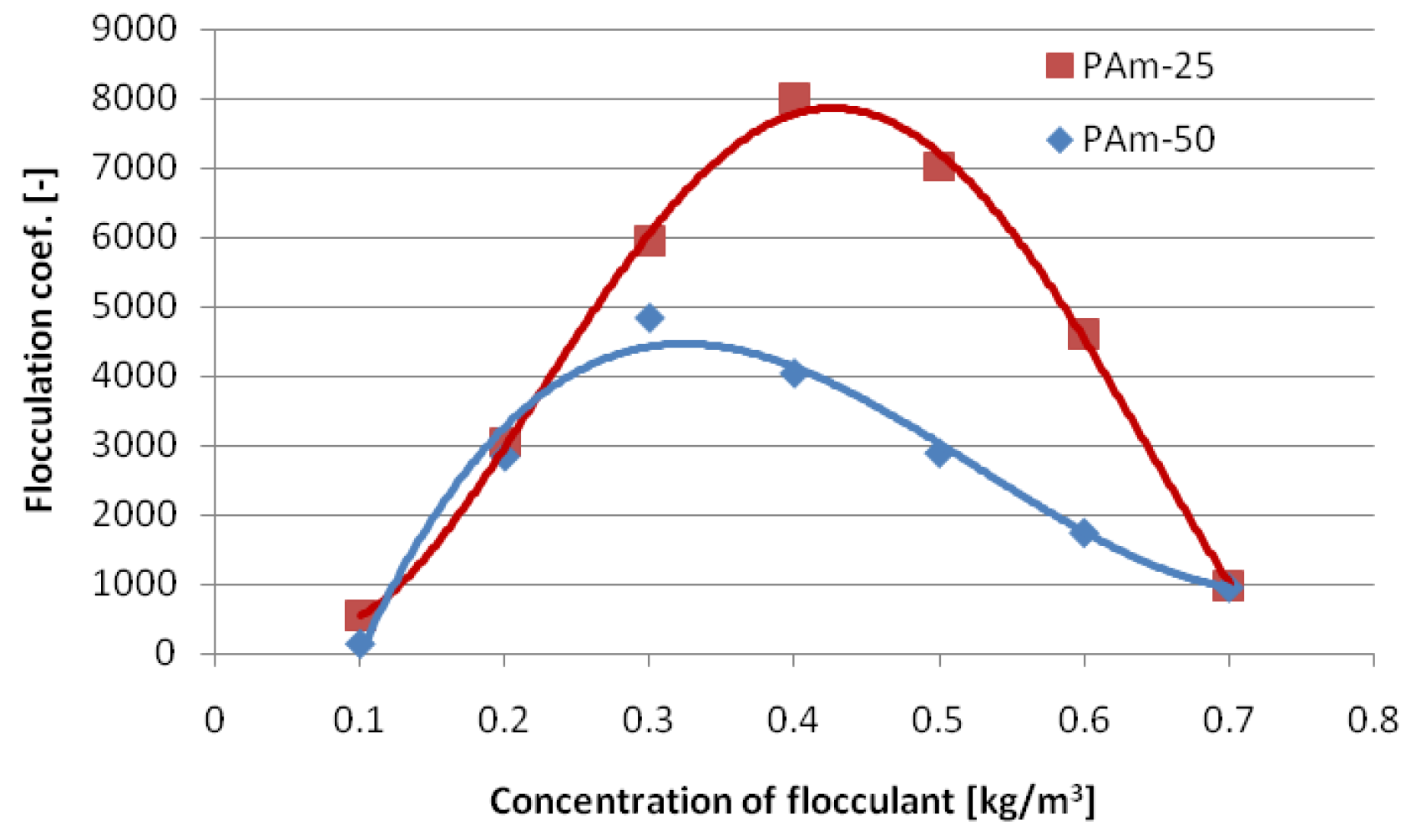
In response to the above, the authors synthesized N-vinylamine polymers PAm-25 and PAm-50 and applied them as flocculants for bentonite-based and spent bentonite-polymer (inhibited) mud generated during HDD and DP drilling operations. The graphs presented in Figure 10 and Figure 11 illustrate the flocculation coefficient of the bentonite-based and bentonite-polymer mud using the synthesized flocculants PAm-25 and PAm-50.
The flocculation of these highly modified, stable bentonite-based and bentonite-polymer dispersions using PAm polymers took only several to several dozen seconds (see Figure 10 and Figure 11). This rapid process can be attributed to the synthesized polymers having an average molecular weight not exceeding 200,000 atomic mass units. Additionally, the polymer chains are relatively short, facilitating the uniform distribution of the flocculant in the spent mud and accelerating the flocculation process. The effectiveness of the newly developed flocculants can be explained by the presence of primary amine groups directly attached to the main polymer chain. As a result, these flocculants exhibit very low steric hindrance. Furthermore, the amine groups carry a relatively high positive charge, which enhances the adsorption onto negatively charged solid-phase particles and eliminates the need for coagulants. Consequently, cationic copolymers with low to medium molecular weight and a low degree of ionicity (10–30%), containing primary amine groups in their structure, have emerged as a new research trend [80,81].
Comparing the two polymers, the polymer with a lower positive charge density (PAm-25) exhibited better flocculating properties than the polymer PAm-50, which contains a higher number of ionic groups (Figure 12). This finding is consistent with the theory that the most effective flocculants are polymers containing approximately 20–30% ionic groups. Consequently, further tests on spent drilling mud were conducted using the PAm-25 polymer.
The initial tests demonstrated that the synthesized polymers can be effectively used as flocculants for clay suspensions such as spent bentonite-based drilling mud. A significant advantage is that the flocculation of the tested clay suspensions was achieved without the use of a coagulating agent. The resulting flocs were large and durable. Another observation supporting the efficiency of the tested flocculants was that the supernatant water above the flocculated sediment was clear. The efficiency of solid-phase separation exceeded 90%, enabling the recovery of over 90% of the water used in the preparation of the drilling mud.
Solid–liquid separation technologies significantly reduce the volume of spent drilling mud and facilitate the subsequent waste processing steps. Furthermore, solid–liquid separation must be integrated with other treatment technologies to ensure a comprehensive approach to waste management. In this context, the authors developed a modified system for managing used drilling mud, with a focus on improving the energy efficiency of the process and enhancing the effectiveness of phase separation.

4. Improving the Energy Efficiency of Drilling Waste Treatment Processes

Drilling waste can contain between 60% and 90% water, depending on the composition, physicochemical properties, and volume of the drilling mud. Due to these factors, waste disposal is a costly and energy-intensive process, as it requires the use of high-efficiency drilling mud treatment systems, including vibrating screens, desanders, desilters, decanter centrifuges, coagulation–flocculation units, and filter presses. These systems are powered by electricity, which, on construction sites, is most commonly generated by diesel-powered generators. As a result, traditional drilling waste management in trenchless technology is associated with high energy consumption, greenhouse gas emissions, and significant operational costs. Depending on the applicable legal regulations, the final cost of disposing 1 m3 of the spent drilling mud generated during HDD and DP operations can be comparable to, or in some cases even higher than, the cost of producing 1 m3 of new drilling mud. These costs include waste disposal fees, electricity costs, and CO2 emission charges.
The authors propose the implementation of photovoltaic panels combined with surface energy storage systems and circular economy (CE) principles to improve the energy efficiency of waste management in trenchless technologies. The energy efficiency management model framework adopted by the authors is based on the following stages:
1. Minimization of drilling waste generation.
This can be achieved by creating suitable conditions for recycling spent drilling mud, including the use of advanced purification equipment and the introduction of chemical destabilization methods to enable effective phase separation. This research conducted by the authors demonstrated that PAm-25 and PAm-50 flocculants are effective in treating bentonite and bentonite-polymer drilling mud. The proposed solution will enable the reuse of water after the drilling mud purification process, which aligns with the principles of the circular economy.
2. Energy analysis and assessment of individual components of drilling mud treatment systems.
To identify key areas of energy consumption and energy losses in the drilling waste management process, the authors reviewed existing drilling mud treatment technologies. They conducted electricity consumption measurements at various stages of the process and analyzed the feasibility of replacing grid electricity with energy from photovoltaic panels.
3. Evaluation of energy efficiency improvements through the integration of photovoltaic panels and surface energy storage systems into drilling waste management in trenchless technologies.
The authors propose utilizing renewable energy sources (RESs) in the form of photovoltaic panels to generate electricity for an on-site drilling mud treatment and waste disposal system. To fully capitalize on the potential of photovoltaic panels, they should be integrated with a high-efficiency surface energy storage system. This solution is expected to reduce the dependence on electricity from diesel-powered generators and contribute to a decrease in CO2 emissions.
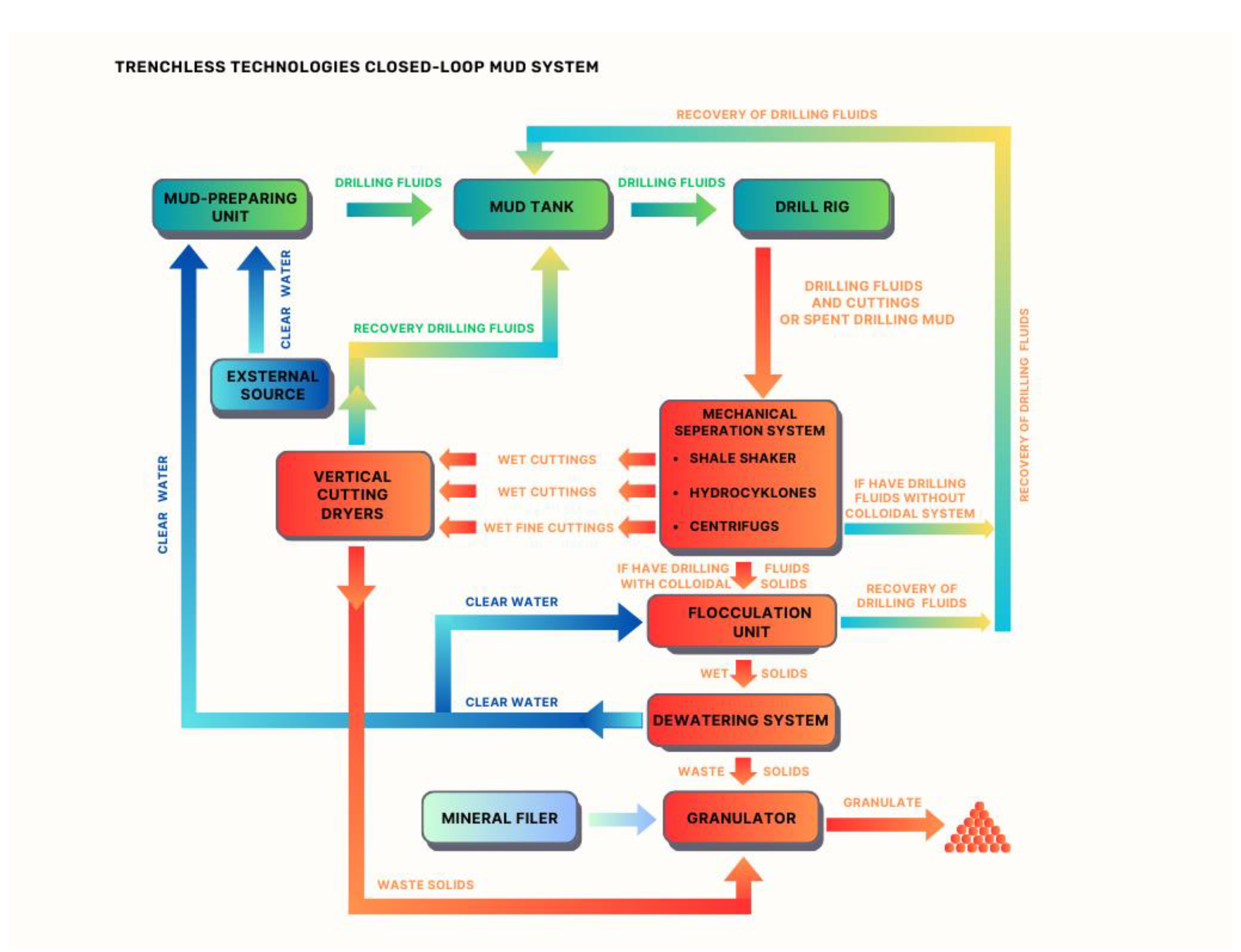
The adopted model for improving energy efficiency in the drilling waste management process in trenchless technologies, along with a market analysis and a review of the available solid control solutions for spent drilling mud, enabled the authors to develop a closed-loop drilling mud management system applicable to HDD and DP technologies. A schematic diagram of this solution is presented in Figure 13.
The primary components of the proposed drilling mud treatment system include shale shakers, hydrocyclones, decanter centrifuges, and a flocculation and dewatering unit for spent drilling mud. Shale shakers, used as a preliminary solid-phase removal element for particles larger than 74 µm, enhance the overall efficiency of the treatment system through various means, such as [78,79,82,83,84,85] installing screens with appropriately sized mesh openings, optimizing the motion characteristics of the screens, or arranging them in a cascading layout.
In a cascading configuration, the first screen acts as the primary separator, capturing larger fractions (rock fragments, gravel), while subsequent screens separate progressively finer fractions [79,82]. Shale shakers should be integrated with hydrocyclone batteries, which remove particles larger than 15 µm. However, a significant drawback of hydrocyclones is their tendency to further fragment the solid phase, which paradoxically complicates the purification of the drilling mud [86,87].
The next step in enhancing the efficiency of drilling mud treatment through mechanical separation is the use of decanter centrifuges. The mechanical separation of solid particles from drilling mud using a decanter centrifuge is a highly effective method for maintaining the appropriate viscosity of the drilling mud. To improve the efficiency of phase separation in decanter centrifuges, the use of a tandem configuration—low-speed and high-speed centrifuges—is recommended. Low-speed centrifuges are primarily used to remove solid particles larger than 5–7 µm from the drilling mud. They are characterized by high flow rates ranging from 350 to 750 L/min and operate at rotational speeds of 1900 to 2200 rpm [75,76]. In contrast, the high-speed centrifuge should be used as the second centrifuge in the system. This centrifuge generates a higher centrifugal force and separates particles ranging from 2 to 5 µm. It operates at speeds of 2500 to 3300 rpm and is fed with flow rates between 150 and 450 L/min. The decanter centrifuges used in HDD or DP technologies should have the largest possible capacity and a drum diameter ranging from 400 to 600 mm [58].
The solid particles remaining in the drilling mud after mechanical purification are of colloidal size. They are not subject to gravitational forces due to the dominance of translational forces (Brownian motion). Therefore, the mechanical purification system should be supplemented with chemical methods. In a traditional drilling mud purification system, the station is equipped with a coagulant and flocculant dosing module, as well as coagulation and flocculation tanks, where the processes of flocculation and coagulation occur. The N-vinylamine polymers synthesized by the authors allow for the elimination of coagulation tanks and flocculation tanks, as flocculation occurs during slow mixing, with a contact time as short as 10 s being sufficient for the separation of suspended solids. The addition of the PAm-25 polymer generates large, stable flocs in the suspension, which withstand high shear forces and can be separated using decanter centrifuges. After centrifugation, a solid waste with a dry matter content of 60 to 70% by weight is obtained. The recovered base fluid can be reused to prepare new drilling muds [35]. The method proposed by the authors eliminates environmentally harmful coagulants from the traditional drilling mud purification system while increasing the efficiency of mud purification. Additionally, it enhances the reusability of the drilling mud and reduces the volume of the drilling waste generated. By using N-vinylamine-based flocculants, it may be possible to omit the “dilution” stages in many cases, further shortening the duration of the mud purification process and thereby reducing electricity consumption and overall process costs.
Furthermore, the waste produced after flocculation and dewatering, due to the absence of electrolyte contamination (a result of eliminating the coagulation process), can be subject to technological processes to convert it into a useful product. For example, through granulation with mineral and/or hydraulic binders, the waste can be transformed into aggregates. This process, in line with a rational waste management policy, can be classified under the category of drilling waste recovery [51,56]
In addition to improving the efficiency of phase separation and reducing the environmental impact of drilling waste, the authors propose powering the closed-loop drilling mud treatment system with renewable energy derived from photovoltaic panels as a further step toward enhancing the energy efficiency of the drilling waste management process. To ensure stable system operation regardless of weather conditions, the authors suggest equipping the system with energy storage units. To this end, the power requirements of the individual components of the drilling mud treatment system were analyzed (Table 4).
The data presented in Table 4 were calculated under the assumption that the drilling mud treatment system operated continuously for 12 h. However, such a scenario is extremely rare, as individual devices typically operate for shorter periods during trenchless drilling operations.
A key factor to consider when generating electricity using photovoltaic panels is their efficiency. The efficiency of solar panels largely depends on their conversion rate, which indicates how much solar energy a photovoltaic panel can convert into electrical energy. This efficiency is expressed as a percentage and is measured under standardized test conditions (STCs). These conditions include solar irradiation of 1000 W/m2 and a temperature of 25 °C. The nominal power of photovoltaic cells is expressed in kilowatt-peak (kWp), a parameter that determines the performance of PV cells under test conditions [88,89]. It is important to note that the irradiation and temperature in the test conditions are constant, whereas these factors fluctuate during real-world operations. The most commonly available PV panels on the market provide nominal power in the range of 250–370 Wp. For instance, BEM-320W Solar Extreme modules offer a nominal power output of 320 Wp [88,89]. Thus, under the test conditions, such a panel mounted on the roof of a drilling mud treatment system should generate 320 watts of electrical power from every 1 kWp of solar power.
Another important consideration is the surface area required for photovoltaic panels to generate the necessary amount of electricity. On average, 1 kWp of solar power (3–4 panels) requires approximately 5–7 m2 of surface area (Table 5). Therefore, the authors propose roofing the drilling mud preparation and treatment system and installing photovoltaic panels on the roof. The roof area above the mud treatment system can measure up to 1000 m2. For example, one HDD drilling contractor uses a pavilion with dimensions of 20 × 50 m.
The analysis of the electricity demand of standard drilling mud treatment equipment, with consideration of process efficiency, indicates that powering such systems solely with photovoltaic panels is not feasible (see Table 4 and Table 5). Photovoltaic panels will serve as a supplementary power source for the drilling mud treatment and waste processing system. Nevertheless, they will reduce the dependence on the energy supplied by the electrical grid or diesel generators. To ensure uninterrupted 12 h system operation under virtually any sunlight condition, the installation of a surface-mounted containerized energy storage system will be necessary (Figure 14).
In Europe, the application of industrial energy storage systems is expected to become a mandatory component of the energy transition in the coming years. Their implementation must also increase in trenchless technologies, contributing to environmental protection and enhancing their perception as technologies powered by green energy.
Currently, most of the surface-mounted energy storage systems are based on lithium-ion cells. These systems are equipped with an energy management system (EMS), an inverter, and a battery system that can be configured according to customer requirements within a power range of 50 kW to several MW and an energy capacity range of 100 kWh to several MWh [90]. These storage capacities are fully sufficient to power the standard mud treatment systems outlined in Table 4. Depending on the requirements, battery modules are housed in cabinets or in specialized shipping containers.

Cost Analysis of Waste Management in Trenchless Technologies

Waste management refers to the adoption of an appropriate strategy for handling generated waste. Currently, the drilling waste produced in trenchless technologies undergoes treatment in drilling mud purification systems before being transported to landfill sites. To evaluate the economic feasibility of different waste management approaches, three variants were considered:
  • Basic variant, involving the separation of the solid phase from the drilling mud using mechanical purification systems equipped only with vibrating screens, desanders, and desilters, followed by the landfill disposal of the waste (Table 6).
  • The most commonly used variant in the drilling industry, which involves solid-phase separation using mechanical purification systems equipped with vibrating screens, desanders, desilters, and decanter centrifuges. After this treatment, the waste is transported to a landfill (Table 7).
  • The authors’ proposed variant, which includes an additional flocculation station and a dewatering unit for post-flocculation drilling mud treatment. The authors propose using a cationic polyvinylamine-based flocculant. To enhance the energy efficiency of the drilling mud purification system, the process is powered by photovoltaic panels (Table 8).
To illustrate these variants, it was assumed that an average of 2.578 m3 of drilling waste per meter of borehole, with a density of 1300 kg/m3, was generated during HDD installations of DN 1000 pipelines. Based on industrial data, the average drilling duration for such a borehole was assumed to be three months, with the productive operation time of the purification system being 40%. The power demand of the drilling mud purification system was calculated based on the average power consumption per hour kWh for each system component, as detailed in Table 4. These data were used to estimate the operational costs of the drilling mud purification system during trenchless drilling operations.
The disposal of generated waste requires a contract with a waste receiver. This contract specifies the cost of disposing of different types of waste. Consequently, the total cost of waste collection can be expressed by Equation (2):
C1 = i1 · K1
where
i1 is the amount of generated waste with code 01 05 04;
K1 is the cost of collecting 1 Mg of waste with code 01 05 04.
In the first variant (Table 6), which includes a minimal treatment system, the cost of treating and disposing of waste at a landfill is approximately PLN 1,187,295. This cost is influenced by the low efficiency of the treatment system, which is only 20%. The electricity cost required to power this treatment system configuration is around PLN 1200 per day. The total energy cost for operating the treatment system throughout the drilling process amounts to PLN 108,000. Consequently, the total waste disposal cost is PLN 1,295,295.
In the second variant (Table 7), after implementing a treatment system equipped with decanter centrifuges, the amount of generated waste can be reduced by 40%. As a result, the volume of waste transported to the landfill decreases to 2001 Mg, and the cost of its disposal amounts to PLN 890,472. The daily operating cost of this treatment system is approximately PLN 1659, while the total energy cost for powering the system is PLN 149,310. Therefore, the total waste disposal cost for this variant is PLN 1,039,782.
The efficiency of the drilling mud treatment system proposed by the authors (see Table 3) was estimated to be approximately 65% on average. This is due to the implementation of a flocculation station, the effectiveness of the proposed cationic polyvinylamine-based flocculant, and the addition of a drilling mud dewatering unit. As a result, the amount of waste requiring management or landfill disposal is 1167 Mg, with an estimated disposal cost of PLN 519,441. In this calculation, the electricity costs for the treatment system were excluded, as the system is powered by photovoltaic energy. The solution proposed by the authors offers cost savings of approximately 49% compared to variant 2 and 60% compared to variant 1.

5. Conclusions

With ongoing urbanization and the sustained demand for energy, the number of transmission networks installed using trenchless methods is steadily increasing. Trenchless technologies are an alternative to traditional methods of installing infrastructure for gas transmission and, in the near future, hydrogen. Trenchless technologies such as HDD and DP are now considered equivalent and are among the most frequently used methods for the trenchless installation of steel pipelines (with diameters exceeding 700 mm) over distances of several hundred meters. To mitigate the anthropogenic impact of these technologies on ecosystems and align them with the principles of the circular economy, it is essential to reduce both the volume and harmfulness of the drilling waste generated. Additionally, improving the energy efficiency of a closed-loop drilling waste management system is necessary.
The conducted research led to the following conclusions and recommendations:
  • The drilling mud after the HDD or DP drilling process only assumes a liquid form. Consequently, it do not meet the basic criterion for waste disposal under Article 55 of the Waste Law [56], which prohibits the disposal of waste in liquid form, including waste containing water at 95% of the total weight.
  • The high values of plastic viscosity negatively affect the process of drilling mud treatment, making it necessary to support mechanical solid-phase removal methods using chemical methods.
  • The chemical destabilization of drilling fluids can be carried out by flocculation methods, using low-molecular-mass cationic–ionic co-polymers as flocculants, which should have high degree of ionicity, containing primary amine groups in their structure, such as the synthesized N-vinylamine polymers PAm-25 and PAm-50.
  • To this study demonstrated that polyvinylamine derivatives containing primary amine groups in their structure can effectively destabilize bentonite-based drilling fluid systems when used for flocculation. As a result, the proposed system enables the separation of drill cuttings and the repeated reuse of purified drilling mud in a closed-loop circuit. This accelerates the drilling process, significantly reduces the wear of the drilling tools and pumps, and lowers the consumption of water and bentonite, thereby increasing the overall profitability of HDD and DP® technologies. At the same time, it aligns with the principles of the circular economy.
  • The proposed drilling mud treatment system can operate in a closed-loop circuit, allowing a significant portion of the waste to be reused either for drilling purposes in another project or as a base for preparing new drilling mud. The waste, after dewatering in the centrifuge, is a mineral material with cohesive, fine-grained properties and a plastic consistency. Due to the elimination of harmful coagulants, this material can be transformed into a useful product, such as aggregates, through granulation with mineral and/or hydraulic binders. This process, in accordance with applicable environmental regulations [51,56], can be classified as recovery.
  • The implementation of RESs, such as photovoltaics combined with a surface-mounted energy storage system, into the drilling mud treatment system can improve the energy efficiency of the process, enhance the role of renewable energy in reducing the carbon footprint, and promote sustainable development.
  • The large-scale implementation of the proposed solution in the trenchless technology industry, by increasing the recovery of raw materials from drilling waste and integrating photovoltaic panels, could improve the energy efficiency of drilling waste treatment processes. Furthermore, it enables the trenchless technology sector to reduce costs and minimize the environmental impact of these operations.
  • The technology proposed by the authors, which involves integrating photovoltaic panels into the management of drilling waste, will require increased financial investment in purchasing photovoltaic installations and energy storage systems. However, in the long term, it will provide financial benefits to companies by reducing the costs associated with purchasing heating oil for power generators and lowering expenses related to CO₂ emissions. Additionally, it will enhance the company’s image as an environmentally responsible entity and enable it to apply for financial support from EU funds for the acquisition of such equipment.

Author Contributions

Conceptualization, A.J., J.Z. and S.W.; methodology, A.J. and S.W.; validation, A.J. and J.Z.; formal analysis A.J. and J.Z.; investigation A.J. and J.Z.; resources A.J. and S.W.; data curation, A.J. and J.Z.; writing—original draft preparation, A.J. and J.Z.; writing—review and editing, A.J.; visualization, A.J. and J.Z.; supervision, A.J. and J.Z.; project administration, A.J. and J.Z.; funding acquisition, A.J. and J.Z. All authors have read and agreed to the published version of the manuscript.

Funding

This research was supported by the program “Excellence Initiative—Research University” of the AGH University of Krakow and project No. 16.16.190.779 from the AGH University of Krakow.

Institutional Review Board Statement

Not applicable.

Informed Consent Statement

Not applicable.

Data Availability Statement

The original contributions presented in this study are included in the article. Further inquiries can be directed to the corresponding author.

Conflicts of Interest

The authors declare no conflicts of interest.

References

  1. Lu, H.; Matthews, J.; Iseley, T. How does trenchless technology make pipeline construction greener? A comprehensive carbon footprint and energy consumption analysis. J. Clean. Prod. 2020, 261, 121215. [Google Scholar] [CrossRef]
  2. Lu, H.; Xi, M.; Azimi, M. US natural gas consumption prediction using an improved kernel-based nonlinear extension of the Arps decline model. Energy 2020, 194, 116905. [Google Scholar] [CrossRef]
  3. Chorazy, T.; Hlavínek, P.; Racek, J.; Pietrucha-Urbanik, K.; Tchórzewska-Cieślak, B.; Keprdová, Š.; Dufek, Z. Comparison of Trenchless and Excavation Technologies in the Restoration of a Sewage Network and Their Carbon Footprints. Resources 2024, 13, 12. [Google Scholar] [CrossRef]
  4. Belani, D.; Pitroda, J.; Bhavsar, J. A Review on Trenchless Technology: State of Art Technology for Underground Utility Services. In Proceedings of the National Conference on: “Trends and Challenges of Civil Engineering in Today’s Transforming World”, Umrakh, India, 29 March 2014; ISBN 978-81-929339-0-0. [Google Scholar]
  5. Najafi, M.; Gokhale, S. Trenchless Technology: Pipeline and Utility Design, Construction, and Renewal, 2nd ed.; McGraw-Hill Education: New York, NY, USA, 2021. [Google Scholar]
  6. Kuliczkowski, A. I Inni. Technologie Bezwykopowe w Inżynierii Środowiska; Wydawnictwo Seidel-Przywecki: Warsaw, Poland, 2019. [Google Scholar]
  7. Naveen, K.K.; Chandramouli, K.; Sree, J.; Naga, C.; Gowreswari, B. A Review on Trenchless Technology. Int. J. Mod. Trends Sci. Technol. 2021, 7, 202–207. [Google Scholar]
  8. Faghih, A.; Goerz, B.; Bayat, A. Stress analysis of steel pipe installation in horizontal directional drilling based on strain monitoring. Tunn. Undergr. Space Technol. 2024, 147, 105673. [Google Scholar] [CrossRef]
  9. Osikowicz, R. Long and Large Diameter HDD Crossings. Top 100 światowych projektów”. Inż. Bezwykopowa 1/2023 r. Available online: https://robertosikowicz.com/wp-content/uploads/2023/03/Top-100_artykul.pdf (accessed on 4 February 2025).
  10. Sparks, A.E.; Hotz, R.D. Direct Pipe Is No Panacea, but it Could be the Right Solution. Available online: https://trenchlesstechnology.com/direct-pipe-is-no-panacea-but-it-could-be-the-right-solution/ (accessed on 19 June 2024).
  11. Gerasimova, V. Undeground Engineering and Trenchless Technologies at the Defense of Environment. Procedia Eng. 2016, 165, 1395–1401. [Google Scholar] [CrossRef]
  12. Bennett, D.; Ariaratnam, S.; Horizontal Directional Drilling (HDD). Good Practices Guidelines, 4th ed.; The North American Society for Trenchless Technology, HDD Consortium: Bothell, WA, USA, 2017. [Google Scholar]
  13. Yan, X.; Ariaratnam, S.T.; Dong, S.; Zeng, C. Horizontal directional drilling: State-of-the-art review of theory and applications. Tunn. Undergr. Space Technol. 2018, 72, 162–173. [Google Scholar] [CrossRef]
  14. Firkowski, M.; Szypuła, K. Pierwsze w Polsce Przekroczenia w Technologii Direct Pipe; Inżynieria Bezwykopowa: Krakow, Poland, 2016. [Google Scholar]
  15. Osikowicz, R. Jakościowa Ocena Procesu Wiertniczego; Inżynieria Bezwykopowa: Krakow, Poland, 2022. [Google Scholar]
  16. Willoughby, D.A. Horizontal Directional Drilling Utility and Pipeline Applications; McGraw-Hill Education: New York, NY, USA, 2005. [Google Scholar]
  17. Wiśniowski, R.; Łopata, P.; Orłowicz, G. Numerical Methods for Optimization of the Horizontal Directional Drilling (HDD) Well Path Trajectory. Energies 2020, 13, 3806. [Google Scholar] [CrossRef]
  18. Osikowicz, R. Planowanie i Realizacja Projektów HDD” cz. I; Inżynieria Bezwykopowa: Krakow, Poland, 2018. [Google Scholar]
  19. Osikowicz, R. Planowanie i Realizacja Projektów HDD” cz. II; Inżynieria Bezwykopowa: Krakow, Poland, 2018. [Google Scholar]
  20. Osikowicz, R. Planowanie i Realizacja Projektów HDD” cz. III; Inżynieria Bezwykopowa: Krakow, Poland, 2018. [Google Scholar]
  21. Osikowicz, R. Planowanie i Realizacja Projektów HDD” cz. IV; Inżynieria Bezwykopowa: Krakow, Poland, 2019. [Google Scholar]
  22. Yan, X.; Ariaratnam, S.T.; Ma, B. World Record 5.2 km HDD Twin Crossings of the Hong Kong Harbor. In Pipelines 2019: Condition Assessment, Construction, and Rehabilitation; ASCE: Reston, VA, USA, 2019. [Google Scholar]
  23. Hermes Science Publishing Ltd. Recommendations French Society for Trenchless Technology, Microtunnneling and Horizontal Drilling; Hermes Science Publishing Ltd.: London, UK, 2004. [Google Scholar]
  24. DCA. DCA Technical Guidelines. Information and Recommendation for the Planning, Construction and Documentation of HDD Projects, 4th ed.; Drilling Contractors Association DCA: Berlin, Germany, 2015. [Google Scholar]
  25. Eising, J.; Kógler, R. Przykładowe Porównanie Kosztów HDD vs Direct Pipe; Inżynieria Bezwykopowa: Krakow, Poland, 2012. [Google Scholar]
  26. Lang, G.; Pfeff, D.; Hayes, B. Direct Pipe as an Alternative to HDD, Method and Case Studies. Herrenknecht AG. Available online: https://www.waternz.org.nz/Attachment?Action=Download&Attachment_id=286 (accessed on 19 June 2023).
  27. Ziaja, J.; Wiśniowski, R.; Jamrozik, A.; Knez, D. Modern construction technologies of gas pipelines and oil pipelines. In Proceedings of the SGEM 2018—18th International Multidisciplinary Scientific Geoconference, Albena, Bulgaria, 2–8 July 2018. [Google Scholar]
  28. Firkowski, M. Technologia Direct Pipe w Skomplikowanych Warunkach Geologicznych; Inżynieria Bezwykopowa: Krakow, Poland, 2020. [Google Scholar]
  29. Krechowicz, M.; Gierulski, W.; Loneragan, S.; Kruse, H. External Risk Factors Evaluation in Horizontal Directional Drilling Technology Using Failure Mode and Effect Analysis. Manag. Prod. Eng. Rev. 2022, 13, 76–88. [Google Scholar] [CrossRef]
  30. Jamrozik, A.; Ziaja, J.; Gonet, A. Analysis of applicability of modified drilling waste for filling out annular space in horizontal directional drilling. Pol. J. Environ. Stud. 2011, 20, 671–675. [Google Scholar]
  31. Como, C. Drilling Fluid Use and Drilling Waste Disposal on HDD Project; Technical Papers; North American Society for Trenchless Technology: Bothell, WA, USA, 2006. [Google Scholar]
  32. Skonberg Eric, R.; Muindi Tennyson, M. Pipeline Design for Installation by Horizontal Directonal Drilling, 2nd ed.; ASCE Manuals and Reports on Engineering Practices No. 108, Horizontal Directonal Drilling Guideline Task Committee of the Technical Committee on Trenchlessinstalation of Piplelines of the Pipleine Divisione of the American Society of Civil Engineers; American Society of Civil Engineers: Reston, VA, USA, 2014. [Google Scholar]
  33. Montazar, R.; Kuo, P.; Chang, S.; Gelinas, M. Analysis and Design of Pipes Installed via Direct Pipe ® Technology. In Proceedings of the NASTT’s 2018 No-Dig Show, Palm Springs, CA, USA, 25–29 March 2018. [Google Scholar]
  34. Robison, J.L.; Arens, N.A. Direct Pipe Construction—An Engineering Perspective on Quality Assurance. In Proceedings of the Pipelines 2017, Phoenix, AZ, USA, 6–9 August 2017. [Google Scholar] [CrossRef]
  35. Jamrozik, A. Możliwości Kompleksowego Recyklingu Odpadowych Płuczek Wiertniczych; Wydawnictwa AGH: Kraków, Poland, 2009. [Google Scholar]
  36. ASME Shale Shaker Committee. Drilling Fluids Processing Handbook; Elsevier INC: London, UK, 2005. [Google Scholar]
  37. Osikowicz, R. Rynek Płynów Wiertniczych; Inżynieria Bezwykopowa: Krakow, Poland, 2013. [Google Scholar]
  38. Kwast-Kotlarek, U.; Hełdak, M.; Szczepański, J. Introducing Bentonite into the Environment in the Construction Stage of Linear Underground Investment Using the HDD Method. Appl. Sci. 2018, 8, 2210. [Google Scholar] [CrossRef]
  39. Bielewicz, D. Płyny Wiertnicze; Wydawnictwa AGH: Kraków, Poland, 2009. [Google Scholar]
  40. Sai, D.; Chao, K.; Alireza, B.; Ergun, K.; Osbak, M.; Barr, K.; Trovato, C. Rheological Properties of Clay-Based Drilling Fluids and Evaluation of Their Hole-Cleaning Performances in Horizontal Directional Drilling. J. Pipeline Syst. Eng. Pract. 2020, 11, 3. [Google Scholar]
  41. Yan, X.; Lan, H.; Moore, I.D.; Ma, B. Flow Properties of Fresh Mud (Drilling Fluid) Used in Horizontal Directional Drilling Pipeline. Syst. Eng. Pract. 2021, 12, 04020063. [Google Scholar] [CrossRef]
  42. American Gas Association, Pipeline Research Committee. Drilling Fluids in Pipeline Installation by Horizontal Directional Drilling; Practical Application Manual. PR-227-9321; American Gas Association, Pipeline Research Committee: Tulsa, OK, USA, 1994. [Google Scholar]
  43. Bueno Sharon, M. Przekroczenie Zatoki Meksykańskiej w Technologii Direct Pipe; Inżynieria Bezwykopowa: Krakow, Poland, 2019; pp. 96–99. [Google Scholar]
  44. Wysocki, S.; Dubiel, S.; Dyndor, D.; Boniecki, A.; Wysocka, M. Clay modifications with biopolymer PT 300308 for HDD muds. AGH Drill. Oil Gas 2009, 26, 1–2. [Google Scholar]
  45. Fijał, J.; Gonet, A.; Jamrozik, A. Characterization, properties and microstructure of spent drilling mud from the point of view of environmental protection. AGH Drill. Oil Gas 2015, 32, 483. [Google Scholar] [CrossRef]
  46. Theng, B.K.W. Formation and Properties of Clay-Polymer Complexes; Elsevier: Amsterdam, The Netherlands, 1979. [Google Scholar]
  47. Jamrozik, A.; Gonet, A.; Fijał, J.; Terpiłowski, K.; Czekaj, L. Analysis of waste mud stability. AGH Drill. Oil Gas 2014, 31, 1. [Google Scholar] [CrossRef]
  48. Steliga, T. Bioremediacja odpadów wiertniczych zanieczyszczonych substancjami ropopochodnymi ze starych dołów urobkowych. Pr. Inst. Naft. I Gazu 2009, 163, 359. [Google Scholar]
  49. EUR Lex, Documents 52021PC0805, COM(20210805—Methane emission reduction in the energy sector (UE) 2019/942. Available online: https://eur-lex.europa.eu/legal-content/EN/TXT/?uri=celex:52021PC0805 (accessed on 4 February 2025).
  50. Osikowicz, R. 30 Lat HDD w Polsce; Inżynieria Bezwykopowa: Krakow, Poland, 2021; Volume 82. [Google Scholar]
  51. DYREKTYWA 2008/98/WE PARLAMENTU EUROPEJSKIEGO I RADY z dnia 19 Listopada 2008 roku w Sprawie Odpadów i Uchylające Niektóre Dyrektywy (Dz.U. L 312 z 22.11.2008, s. 3); European Union: Brussels, Belgium, 2008.
  52. DYREKTYWA 2006/21/WE PARLAMENTU EUROPEJSKIEGO I RADY z dnia 15 Marca 2006 r. w Sprawie Gospodarowania Odpadami Pochodzącymi z Przemysłu Wydobywczego oraz Zmieniająca Dyrektywę 2004/35/WE; European Union: Brussels, Belgium, 2006.
  53. Rozporządzenie Komisji (UE) nr 1357/2014 z dnia 18 Grudnia 2014 r. Zastępującego Załącznik III do Dyrektywy Parlamentu Europejskiego i Rady 2008/98/WE w Sprawie Odpadów oraz Uchylającej Niektóre Dyrektywy (Dz. Urz. UE L 365 z 19.12.2014, str. 89, z późn. zm.); European Union: Brussels, Belgium, 2014.
  54. Dyrektywa Rady 1999/31/WE z dnia 26 Kwietnia 1999 r. w Sprawie Składowania Odpadów (Dz.U. UE. L 182 z 16.07.1999 wraz z późn. zm.); European Union: Brussels, Belgium, 1999.
  55. Ustawa z dnia 27 kwietnia 2001 r.—Prawo ochrony środowiska (tekst jedn. Dz.U. z 2021 r., poz. 1973 ze zm.). Available online: https://isap.sejm.gov.pl/isap.nsf/download.xsp/WDU20210001973/T/D20211973L.pdf (accessed on 4 February 2025).
  56. USTAWA z dnia 14 grudnia 2012 r. o odpadach (Dz.U. 2022 r. poz.699). Available online: https://isap.sejm.gov.pl/isap.nsf/download.xsp/WDU20220000699/T/D20220699L.pdf (accessed on 4 February 2025).
  57. USTAWA z dnia 10 lipca 2008 r. o odpadach wydobywczych (Dz.U. 2022 r. poz. 2336). Available online: https://isap.sejm.gov.pl/isap.nsf/download.xsp/WDU20220002336/T/D20222336L.pdf (accessed on 4 February 2025).
  58. Ptak, S. Utylizacja Płuczki Wiertniczej Stosowanej w Projektach HDD; Inżynieria Bezykowa: Krakow, Poland, 2019. [Google Scholar]
  59. 360iResearchTM. Drilling Waste Management Market by Waste Type (Contaminated Equipment Wastes, Cuttings Wastes, Drilling Fluid Wastes), Treatment Processes (Bioremediation, Chemical Treatment, Solidification/Stabilization), Service Providers, End User Industries, Equipment, Technology—Global Forecast 2025–2030; 360iResearchTM: Maharashtra, India, 2024. [Google Scholar]
  60. ONZ. Transforming Our World: The 2030 Agenda for Sustainable Development; Resolution adopted by the General Assembly on 25 September 2015; Available online: https://docs.un.org/en/A/RES/70/1 (accessed on 4 February 2025).
  61. Serwis Rzeczypospolitej Polskiej. Cele Zrównoważonego Rozwoju. Available online: https://www.gov.pl/web/rozwoj-technologia/cele-zrownowazonego-rozwoju (accessed on 19 November 2024).
  62. Shahbaz, M.; Rashid, N.; Saleem, J.; Mackey, H.; McKay, G.; Al-Ansari, T. A review of waste management approaches to maximise sustainable value of waste from the oil and gas industry and potential for the State of Qatar. Fuel 2023, 332, 126220. [Google Scholar] [CrossRef]
  63. Kazamias, G.; Zorpas, A.A. Drill cuttings waste management from oil & gas exploitation industries through end-of-waste criteria in the framework of circular economy strategy. J. Clean. Prod. 2021, 322, 129098. [Google Scholar] [CrossRef]
  64. Hossain, M.E.; Al-Majed, A.; Adebayo, A.R.; Apaleke, A.S.; Rahman, S.M. A Critical Review of Drilling Waste Management Towards Sustainable Solutions. Environ. Eng. Manag. J. (EEMJ) 2017, 16, 1435–1450. [Google Scholar] [CrossRef]
  65. Lebedev, A.; Cherepovitsyn, A. Waste Management during the Production Drilling Stage in the Oil and Gas Sector: A Feasibility Study. Resources 2024, 13, 26. [Google Scholar] [CrossRef]
  66. Shen, B.; Khanal, M.; Shi, J.; Mallants, D. Modelling geomechanical stability of a large deep borehole in shale for radioactive waste disposal, Incorporating Trenchless Technology Research. Tunn. Undergr. Space Technol. 2024, 145, 105606. [Google Scholar] [CrossRef]
  67. Chandan, K.K.; Chauhan, V.K.S. Review of Polymers and Coagulants Used for Flocculation of Drilling Fluid. In Recent Advances in Materials. ICSTE 2023; Swain, B.P., Ed.; Springer Proceedings in Materials; Springer: Singapore, 2023; Volume 25. [Google Scholar] [CrossRef]
  68. Liu, Y.; Zhang, Y.; Xie, T.; Yue, M.; Wang, D.; Li, B. The Study of Optimization of Flocculation and Destabilization Technology of Waste PEM Drilling Fluid in Bohai Oilfield. Front. Energy Res. 2021, 9, 796786. [Google Scholar] [CrossRef]
  69. Yang, J.; Sun, J.; Wang, R.; Qu, Y. Treatment of drilling fluid waste during oil and gas drilling: A review. Environ. Sci. Pollut. Res. 2023, 30, 19662–19682. [Google Scholar] [CrossRef]
  70. Goneta, A. Metody Przetwarzania Organiczno-Mineralnych Odpadów Wiertniczych w Aspekcie ich Zagospodarowania; Wydział Wiertnictwa, Nafty i Gazu Akademii Górniczo-Hutniczej im. ST Staszica w Krakowie: Kraków, Poland, 2006. [Google Scholar]
  71. Fischer, T.; Heitz, W. Synthesis of polyvinylamine and polymer analogous reactions. Macromol. Chem. Phys. 1994, 195, 679–687. [Google Scholar] [CrossRef]
  72. PN-EN ISO 10414; Część 1 Płyny Wiertnicze—“Przemysł Naftowy i Gazowniczy. Badania Polowe Płynów Wiertniczych. International Organization for Standardization: Geneva, Switzerland, 2008.
  73. Standard Techniczny ST-IGG-3301:2021; Technologie Bezwykopowe, Horyzontalne Przewierty Sterowane. Izba Gospodarcza Gazownictwa: Warsaw, Poland, 2021.
  74. Wiśniowski, R.; Skrzypaszek, K.; Małachowski, T. Selection of a Suitable Rheological Model for Drilling Fluid Using Applied Numerical Methods. Energies 2020, 13, 3192. [Google Scholar] [CrossRef]
  75. Shu, B.; Ma, B.; Zeng, C.; Lan, H. Preparation and Recycling of Drilling Mud in Large Scale Horizontal Directional Drilling Projects in Mainland China. In Proceedings of the ICPTT 2011: Sustainable Solutions for Water, Sewer, Gas, and Oil Pipelines, Beijing, China, 26–29 October 2011. [Google Scholar]
  76. Macnar, K.; Gonet, A.; Stryczek, S. Dewatering and neutralization of waste drilling muds. In Proceedings of the Mineralogia—Special Papers. MECC’08: 4th Mid-European Clay Conferenc, Zakopane, Poland, 22–27 September 2008. [Google Scholar]
  77. Osikowicz, R. Zamknięty Obieg Płuczkowy, cz. II: Selekcja Parametrów; Inżynieria Bezwykopowa: Krakow, Poland, 2016. [Google Scholar]
  78. M-I Drilling Fluids, Schlumberger Company. Solids Control Solutions for HDD, Mining & Waterwell. Reduce Waste, Recover More Fluid, and Increase Performance. Available online: https://www.slb.com/products-and-services/innovating-in-oil-and-gas/drilling/drilling-fluids-and-well-cementing/solids-control/solids-control-solutions-for-hdd-mining-and-waterwell (accessed on 31 July 2024).
  79. Schlumberger Company. HDD, Mining & Waterwell. Products Used to Drill Vertical Hole in Australian Subsidence Zone. Available online: https://www.slb.com/resource-library/case-study/mi/hdd-mww-boart-australia (accessed on 31 July 2024).
  80. Wysocki, S.; Bielewicz, D.; Wysocka, M. Flokulacja Suspensji Ilastych i Płuczek Wiertniczych z Zastosowaniem Nowo Opracowanych Flokulantów Kationowych; Wydawnictwa AGH Wiertnictwo, Nafta, Gaz: Kraków, Poland, 2009. [Google Scholar]
  81. Wysocki, S. Flokulacja Suspensji Ilastych i Zasolonych Płuczek Wiertniczych z Zastosowaniem Nowo Opracowanych Flokulantów Kationowych (PT-FLOC-201107); Wydawnictwa AGH Wiertnictwo, Nafta, Gaz: Kraków, Poland, 2010. [Google Scholar]
  82. Rai, A.M. Principles of Solids Control. 29 October 2013. Trenchles Technology. Available online: https://trenchlesstechnology.com/principles-of-solids-control/ (accessed on 31 July 2024).
  83. American Assosation of Drilling Engineers. Shale Shakers and Drilling Fluids System; American Assosation of Drilling Engineers: Houston, TX, USA, 2014. [Google Scholar]
  84. Osikowicz, R. Zamknięty Obieg Płuczkowy Część I: IDEA; Inżynieria Bezwykopowa: Krakow, Poland, 2016; Volume 1. [Google Scholar]
  85. Bayer, H.J. HDD Practice Handbook; Vulkan-Verlag GmbH: Essen, Germany, 2005. [Google Scholar]
  86. Clark, B.; Sorteberg, B. Centrifuges Improve Directional Drilling Operations and Reduce Disposal Costs; Trenchless Technology: Richfield, OH, USA, 2015. [Google Scholar]
  87. Zou, J.; Zhu, H.; Wang, F.; Sui, H.; Fn, J. Preparation in a new inorganic-organic composite flocculant used in solid-liquid separation for waste drilling fluid. Chem. Eng. J. 2011, 171, 350–356. [Google Scholar] [CrossRef]
  88. Jaka Jest Wydajność Paneli Fotowoltaicznych. Portal Akademia fotowoltaiki.pl. Available online: https://akademia-fotowoltaiki.pl/wydajnosc-paneli-fotowoltaicznych/ (accessed on 31 July 2024).
  89. Biernaciak, E. Sprawność Paneli Fotowoltaicznych—6 Najważniejszych Informacji. Portal ENERGIA.pl. Available online: https://enerad.pl/sprawnosc-paneli-fotowoltaicznych-6-najwazniejszych-informacji/ (accessed on 31 July 2024).
  90. Marat, A. Magazyny energii—inteligentne zarządzanie energią na przykładzie Automatic System Engineering. Energetyka Rozproszona 2022, 8, 69–74. [Google Scholar] [CrossRef]
Figure 1. Classification of trenchless pipeline construction technologies.
Energies 18 00788 g001
Figure 2. Stages of drilling a hole using HDD technology.
Energies 18 00788 g002
Figure 3. Typical drilling fluid composition for HDD and DP technologies (adopted from [36,39]).
Energies 18 00788 g003
Figure 4. Total volumes of drilling waste in HDD and DP technologies.
Energies 18 00788 g004
Figure 5. Value of the global drilling waste market (adopted from [59]).
Energies 18 00788 g005
Figure 6. Strategies for improving the energy efficiency in the management of the drilling waste generated by trenchless technologies.
Energies 18 00788 g006
Figure 7. Structural formula of polyvinylamine (PAm).
Energies 18 00788 g007
Figure 8. X-ray diffraction pattern of the spent bentonite-based drilling mud.
Energies 18 00788 g008
Figure 9. SEM image of the spent bentonite mud sample showing the presence of clay mineral aggregates and calcite (point 2) as well as pieces, among others, of quartz, drill cuttings (point 1), and feldspars (point 3).
Energies 18 00788 g009
Figure 10. Flocculation coefficient of the suspension of the spent bentonite-based (1) and bentonite-polymer spent drilling mud (2) with the flocculant PAm-25.
Energies 18 00788 g010
Figure 11. Flocculation coefficient of spent bentonite-based (1) and bentonite-polymer drilling mud (2) with the flocculant PAm-50.
Energies 18 00788 g011
Figure 12. Comparison of the flocculating properties of the two PAm polymers tested.
Energies 18 00788 g012
Figure 13. Closed-loop drilling waste management system applicable to HDD and DP technologies.
Energies 18 00788 g013
Figure 14. Diagram of the use of photovoltaic panels mounted on a pavilion protecting the drilling mud preparation and treatment system for HDD and DP technology. 1—Pavilion for the mud treatment system, 2—photovoltaic panels, 3—energy storage, 4—HDD drilling rig.
Energies 18 00788 g014
Table 1. Comparison of HDD and Direct Pipe® trenchless methods with excavation methods.
ParameterOpen ExcavationHDDDirect Pipe®
Earth worksOver entire lengthMinimal (only on the entry and outlet sides)Moderate (shallow entry and outlet chambers)
Potential collisions with underground infrastructureFrequentVery rareVery rare
Environmental impactMaximalMinimalMinimal
Safety of installationModerateVery highVery high
Time of installationVery longVery shortShort
Assembly line of the pipelineRequired over entire lengthOnly on one side of the pipelineOnly on the machine side
Assembling of systems and toolsEasyVery easyComplex and time-consuming
EquipmentVery big, standard equipmentSmall, only specialist equipmentSmall, only specialist equipment
Consumption of drilling fluids materialsNoHighModerate
Reconstruction of river beds and surface infrastructureCompleteNoNo
Meteorological impactMaximalMinimalMinimal
Protection of surface watersMinimalMaximalMaximal
Limitations of the methodDeep, broad water courses, swamps, natural reserveHigh-pressure groundwaterModerate and big distances only
Ability to cover complex trajectoriesUnlimitedModerate curveSmall-curvature radii
Average cost of construction of 1 mb of pipelineLowMediumHigh
Table 2. Selected physical and chemical properties of spent bentonite-based drilling mud used in trenchless technologies.
ParameterUnitValue
Min.Max.Average
Density inkg/m31.031.181.105
Density outkg/m31.051.251.15
600 rpmoFann37.6109.573.55
300 rpmoFann318256.5
Plastic viscosity [PV]mPas6.127.516.8
Yield point [YP]Pa8.731.3620.04
Gel 10′′/10′Pa8.81/9.1027.00/44.0017.91/26.5
Rheological model-Herschel–BulkleyHerschel–Bulkley-
pH of filtrate-7.9010.008.95
API filtrationml5.025.015.0
Electrolyte conductivitymS/cm104039002470
Solid vol. in/out%3.3/11.514.1/17.58.7/14.5
Capillary water absorption time tcsts54,000>86,40070,200
Table 3. Phase composition of the analyzed spent bentonite-based drilling mud.
Type of MudIdentified PhaseICDD Code *
Bentonite-basedCalcite (CaCO3),
Quartz (Q)
Dolomite (D)
Illite (I)
Chlorite (Ch)
Kaolinite (K)
Na-smektite (M)
Amorphous phase
24-0027
33-1161
34-0517
26-0911
16-0362
06-0221
12-0204
-
* from the International Centre for Diffraction Data (ICDD) catalogue.
Table 4. Standard drilling mud treatment systems used in trenchless technologies with electric power requirements.
Type of EquipmentShift Power Demand [kW]Average Power Consumption per Hour [kWh]Motor Rated Power [kW]Average Operating Time per Shift [h]Operating Time with Energy Storage per Shift [h]Demand for Energy Storage [kWh]
Shale shakers12010158440
Desanders320274084108
Desilters 16013404226
Decanter centrifuges 20017504234
Flocculation unit21618404236
Total1016851852814244
Table 5. Solar power and total panel surface area required to generate 1 kWh and 100 kWh energy of electricity for various panel efficiencies.
Type of Scenario in the Context of Power DemandPessimistic VariantNumber of PanelsRealistic VariantNummer of PanelsOptimistic VariantNumber of Panels
Electric power [kW]0.2510.310.351
Solar power [kWp]1413.3312.86
Panel surface area [m2] for 1 kWp solar power6.85.74.9
Electric power [kW]100
Solar power [kWp] required for 100 kW electric power4001600333.31112285.7817
Total panel surface area [m2]272018891388
Table 6. Data assumed for the economic analysis of the first variant of drilling mud treatment for a 1000 m borehole.
ParameterValueUnit
i1—Amount of generated waste with code 01 05 043335Mg
K1—Cost of collecting 1 Mg of waste with code 01 05 04445PLN/Mg
W1st—Efficiency of the drilling waste treatment system20%
Pe—Power demand of the drilling mud treatment system348kW
Ce—Cost of electricity obtained from diesel generators3.4PLN/kWh
Table 7. Data assumed for the economic analysis of the second variant of drilling mud treatment for a 1000 m borehole.
ParameterValueUnit
i1—Amount of generated waste with code 01 05 043335Mg
K1—Cost of collecting 1 Mg of waste with code 01 05 04445PLN/Mg
W1st—Efficiency of the drilling waste treatment system40%
Pe—Power demand of the drilling mud treatment system
without a flocculation unit
416kW
Ce—Cost of electricity obtained from diesel generators3.4PLN/kWh
Table 8. Data assumed for the economic analysis of the third variant of drilling mud treatment for a 1000 m borehole.
ParameterValueUnit
i1—Amount of generated waste with code 01 05 043335Mg
K1—Cost of collecting 1 Mg of waste with code 01 05 04445PLN/Mg
W1st—Efficiency of the drilling waste treatment system64%
Pe—Power demand of the drilling mud treatment system
with a flocculation unit and dewatering
488kW
Disclaimer/Publisher’s Note: The statements, opinions and data contained in all publications are solely those of the individual author(s) and contributor(s) and not of MDPI and/or the editor(s). MDPI and/or the editor(s) disclaim responsibility for any injury to people or property resulting from any ideas, methods, instructions or products referred to in the content.