Article

Development and Performance Analysis of an Electromagnetic Pump for a Thermal Hydraulic Experimental Loop of a Lead-Cooled Fast Reactor

1
Department of Nuclear Science and Technology, Shaanxi Key Laboratory of Advanced Nuclear Energy and Technology, Xi’an Jiaotong University, Xi’an 710049, China
2
State Key Laboratory of Advanced Nuclear Energy Technology, Nuclear Power Institute of China, Chengdu 610213, China
*
Author to whom correspondence should be addressed.
Energies 2025, 18(3), 750; https://doi.org/10.3390/en18030750
Submission received: 6 November 2024 / Revised: 21 December 2024 / Accepted: 1 February 2025 / Published: 6 February 2025
(This article belongs to the Special Issue Thermal Hydraulics and Safety Research for Nuclear Reactors)

Abstract

:
With the advancement of lead–bismuth fast reactors, there has been increasing attention directed towards the design of and manufacturing technology for electromagnetic pumps employed to drive liquid lead–bismuth eutectic (LBE). These electromagnetic pumps are characterized by a simple structure, effective sealing, and ease of flow control. They exploit the excellent electrical conductivity of liquid metals, allowing the liquid metal to be propelled by Lorentz forces generated by the traveling magnetic field within the pump. To better understand the performance characteristics of electromagnetic pumps and master the techniques for integrated manufacturing and performance optimization, this study conducted fundamental research, development of key components, and the assembly of the complete pump. Consequently, an annular linear induction pump (ALIP) suitable for liquid lead–bismuth eutectic was developed. Additionally, within the lead–bismuth thermal experimental loop, startup and preheating experiments, performance tests, and flow-head experiments were conducted on this electromagnetic pump. The experimental results demonstrated that the output flow of the electromagnetic pump increased linearly with the input current. When the input current reached 99 A, the loop achieved a maximum flow rate of 8 m3/h. The efficiency of the electromagnetic pump also increased with the input current, with a maximum efficiency of 5.96% during the experiments. Finally, by analyzing the relationship between the flow rate and the pressure difference of the electromagnetic pump, a flow-head model specifically applicable to lead–bismuth electromagnetic pumps was established.

1. Introduction

In 2002, the U.S. Department of Energy initiated the Generation IV International Forum (GIF), which selected six of the most promising advanced reactor designs, including lead-cooled fast reactors (LFRs) and sodium-cooled fast reactors (SFRs) [1,2]. In particular, the LFR design is regarded as one of the most promising fourth-generation nuclear energy systems [3]. LFRs can meet the requirements for nuclear fuel breeding and transmutation, making then a key solution to the global energy crisis [4]. With the development of lead-cooled fast reactor technologies, electromagnetic pumps (EMPs) used to drive liquid metals have attracted increasing attention. Electromagnetic pumps have been widely utilized in the cooling systems of LFRs and SFRs. In comparison to mechanical pumps, an EMP offers advantages such as a simple structure, absence of mechanical parts, easy of flow rates control, and long-term operational stability. However, EMPs also exhibit drawbacks such as relatively low flow rates and efficiency [5].
An electromagnetic pump (EMP) drives liquid metals based on the principle of electromagnetic induction. When the electromagnetic coil is energized, a traveling magnetic field is generated within the EMP. The liquid metal passively cuts magnetic flux lines to generate induced current and flows directionally under the influence of the Lorentz force in the magnetic field. Based on the method through which the induced currents are generated in the liquid metal, EMPs can be classified into conductive pumps and inductive pumps. Furthermore, depending on the configuration of the liquid metal flow channels, EMPs can be subdivided into planar pumps, helical pumps, and annular pumps. The specific classification method of electromagnetic pumps is shown in Figure 1. The lead–bismuth electromagnetic pump designed and developed in this study is an annular linear induction pump (ALIP). An ALIP provides higher output flow rates and pumping efficiency than other types of EMP and exhibits enhanced structural stability [6].
The concept of an EMP was first proposed in the 19th century by Einstein and Szilard. In 1907, Northup initiated research on electromagnetic pumps [7]. Early electromagnetic pumps were primarily conduction-type pumps with low flow rates. These pumps were mainly used in the metallurgy and casting industries. In the 1950s, with the development of SFRs and LFRs, the demand for high-flow electromagnetic pumps began to increase. Although conduction electromagnetic pumps have a simple principle and structure, their low absolute efficiency and low relative flow rates and efficiency compared to induction pumps led to a shift in research focus towards induction pumps [8]. In 1997, Argonne National Laboratory in the U.S. introduced a liquid lead–bismuth induction pump manufactured by General Electric for its liquid metal reactor design, which successfully passed tests for equipment longevity, temperature resistance, and radiation tolerance [9]. In 2004, Hiroyuki et al. from Toshiba Corporation of Japan designed and manufactured an ALIP intended to operate in a liquid sodium environment [10]. Experimental tests demonstrated that its key performance parameters met the design requirements. Sharma et al. presented the design of a high-flow ALIP (170 m3·h−1) intended for the secondary liquid metal sodium filling and exhaust system in the Indian sodium-cooled Prototype Fast Breeder Reactor (PFBR) in 2011 [11]. They also conducted performance tests on the electromagnetic pump.
In recent years, many scholars have extensively studied theoretical models of EMPs. In 2014, Nashine et al. conducted a theoretical study on ALIPs based on the equivalent circuit method [12] and derived the relationship between flow rate and pressure head. In 2016, Kim et al. conducted a theoretical analysis of ALIPs based on magnetohydrodynamics (MHD) and analyzed the influence of structural parameters such as pole pair number and core size on the pressure head and efficiency of EMPs [13]. In 2019, Wang et al. conducted experimental research and performance optimization design for a small-flow sodium ALIP and developed a flow-head model that was corrected based on experimental data [14]. The aforementioned research work primarily focuses on sodium electromagnetic pump. These theoretical models show significant discrepancies in predicting the lead–bismuth electromagnetic pump developed in this study.
This study focuses on the design and development of a lead–bismuth electromagnetic pump, which was carried out based on the theoretical model of EMPs. Through experimental research, the performance characteristics of the developed electromagnetic pump were analyzed, and a flow-head model applicable to small-flow lead–bismuth electromagnetic pumps was proposed. This work provides valuable guidance for the further development of lead–bismuth electromagnetic pumps. In this paper, Section 2 mainly introduces the derivation process of the theoretical model of the EMP, Section 3 mainly introduces the development of the EMP, Section 4 shows the experiments carried out in this study and the relevant conclusions obtained, and Section 5 is a summary of the above contents.

2. Mathematical and Physical Model

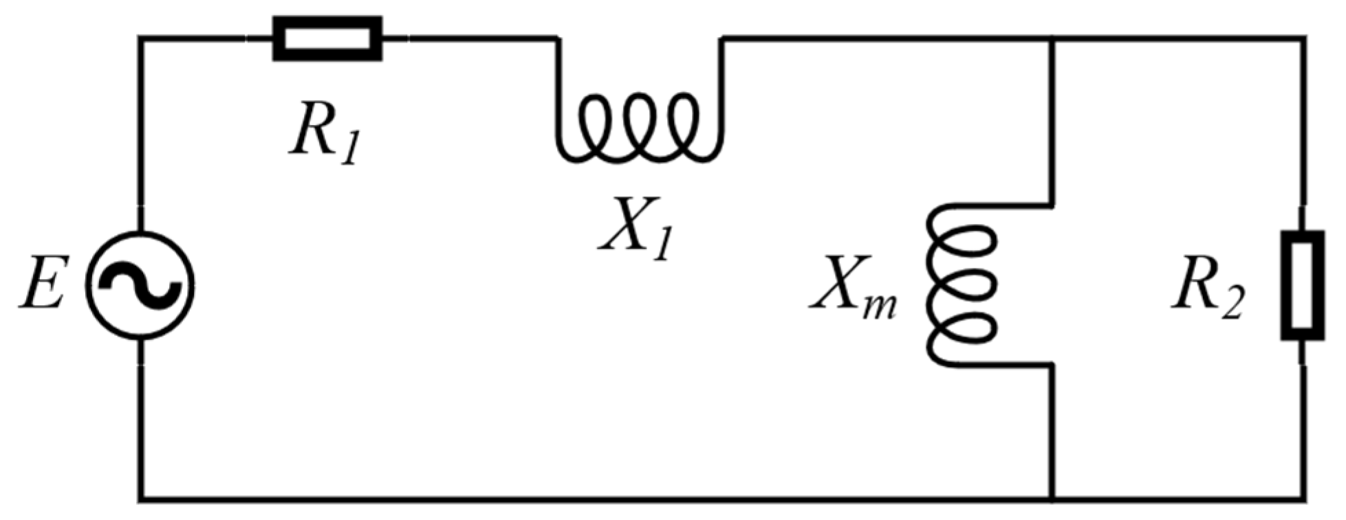
2.1. Equivalent Circuit Model

The basic principle of an EMP is similar to that of a three-phase asynchronous motor [15]. According to motor theory, the structural components are typically divided into two parts: the primary and secondary sections. The primary section consists of the center and external iron cores and electromagnetic coils, while the secondary section includes the liquid lead–bismuth and the walls of the annular flow channel [16]. Figure 2 shows the equivalent circuit model of the electromagnetic pump [6]. The single-phase equivalent circuit of the EMP is composed of the primary equivalent resistance R1, equivalent leakage reactance X1, secondary equivalent resistance R2, and magnetizing reactance Xm.
The parameters in the equivalent circuit of the electromagnetic pump are as follows [17]:
R 1 = π r C u q k p 2 M 2 D 0 N 2 k f k d p τ 2
X 1 2 π μ 0 ω D 0 λ c N 2 p q
X m = 6 μ 0 ω τ π D 0 k w N 2 π 2 p G e
R 2 = 6 π D a n n u l a r r s s k w N 2 τ p
Due to the differences between the internal structure of the electromagnetic pump and the motor in the aforementioned model, a re-evaluation and a detailed explanation of the individual components within the circuit are necessary.

2.1.1. Primary Equivalent Resistance

The primary resistance is composed of the resistance of the winding coil. The winding coil is primarily made of copper. The resistance of a single winding coil can be calculated using the following equation:
R c o i l = r C u N L c o i l A c o i l
For the stator winding of the Q-slot, its total resistance is given by
R 1 = Q r C u N L c o i l A c o i l
The resistivity of copper varies with temperature and is expressed by the equation below [18]. Typically, the resistivity is calculated using the experimentally measured average temperature of the coil.
r C u = 0.0178 × 1 + T C u 293.15 × 0.0039 × 10 6

2.1.2. Equivalent Leakage Reactance

In the magnetic flux generated by the winding coil, a part of the flux is linked only to the winding itself. This part includes the leakage flux Φ1 passing through the winding coil and the leakage flux Φ2 coupled with the coil, as shown in Figure 3. Considering a differential segment of length dx as the object, the magnetic flux dΦ through this segment can be expressed as
d Φ = Φ | d x = F | d x R m | d x = μ 0 π D i Q I D c o i l d c o i l x d x
At the inlet and outlet of the electromagnetic pump, specifically at the ends of the electromagnetic coils, end effects typically occur, resulting in an axially non-uniform magnetic field distribution [19]. To simplify calculations, it is assumed that the magnetic field is uniformly distributed along the axial direction of the EMP. The total magnetic flux coupled by the coil can be calculated by the following formula:
ψ = Q Φ = L I
The inductance at the coil can be expressed as
L 1 = 1 I Q d Φ = 1 I 0 D c o i l Q x D c o i l μ 0 π D i Q I D c o i l d c o i l x d x = μ 0 π D i Q 2 d c o i l 3 D c o i l
Similarly, the inductance at the air gap can be expressed as
L 2 = μ 0 π D j D a i r Q 2 D c o i l
The total inductance of the winding coil consists of two components:
L = L 1 + L 2
The primary leakage impedance is given by
X 1 = 2 π f L Q = 2 π 2 μ 0 f Q ( D j d c o i l + 3 D j D a i r ) 3 D c o i l

2.1.3. Secondary Equivalent Resistance

The secondary resistance consists of the equivalent resistance of the liquid metal and the resistance of the pipe walls of the annular channel. When liquid LBE flows through the annular channel, it continuously cuts magnetic flux lines in the alternating magnetic field, inducing an electromotive force. If the liquid lead–bismuth within the flow channel is considered a conductive medium, its equivalent resistance can be calculated using the following formula:
R L B E = r L B E D ¯ a n n u l a r d a n n u l a r L s t a t o r
The resistivity of LBE varies with temperature and is expressed by the equation below [20]. In this study, the LBE temperature at the EMP inlet was controlled at 250 °C during the experiments. Therefore, the resistivity of LBE at 250 °C was used to calculate the equivalent resistance.
r L B E = 90.9 + 0.048 T L B E 293.15 × 10 8
The resistance of the pipe walls of the annular channel is primarily composed of the resistance of the inner wall surface Rw,in and the resistance of the outer wall surface Rw,out. This resistance can be calculated using the following formulas:
R w , i n = r s s π D ¯ a n n u l a r d w , i n
R w , o u t = r s s π D ¯ a n n u l a r d w , o u t

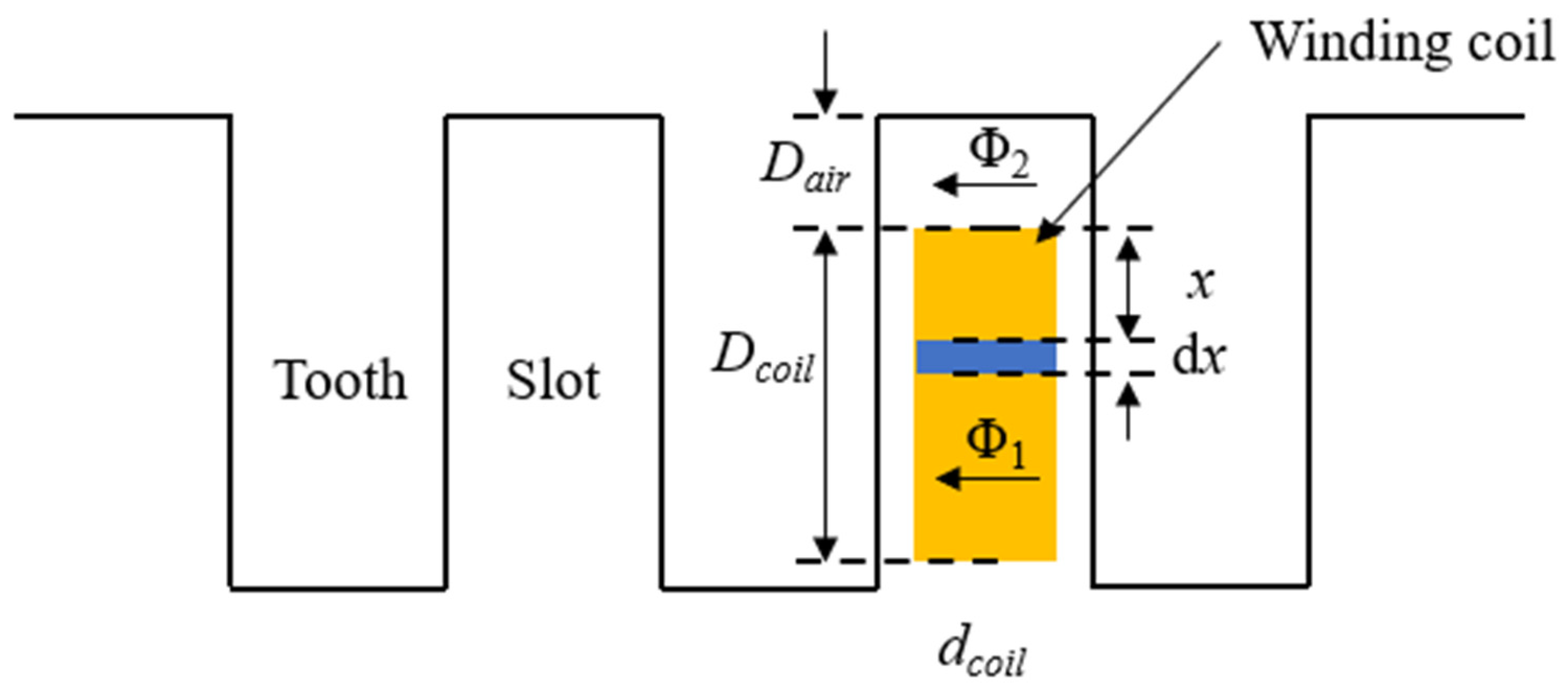
2.1.4. Magnetizing Reactance

For the magnetic flux within a magnetic pole,
Φ p = B p A B = B p π D ¯ a n n u l a r τ
The magnetomotive force amplitude FB in the airgap of the EMP is given by
F B = H L B = B m μ 0 d a i r g a p
For a single-phase winding coil, the harmonic magnetomotive force (MMF) is typically neglected [12], and the analysis primarily focuses on the fundamental wave MMF. The amplitude of the fundamental wave MMF can be calculated using the following formula [21]:
F 1 = 4 π Q k w 2 p I ϕ cos θ
For the fundamental MMF of a three-phase winding,
F 3 = 1.35 Q k w p I ϕ cos ω t θ
The amplitude of its MMF is given by
F m = 1.35 Q k w p i ϕ
By simultaneously solving Equations (17) and (20), the amplitude of the magnetic flux density Bm can be obtained as
B m = 1.35 μ 0 N k w I ϕ d a i r g a p p
The total induced electromotive force (EMF) is given by
E B = E m 2 = ω Q Φ m 2 = 2 π f Q B m A B
Considering the multi-slot winding coil, the expression for the magnetization impedance is obtained as follows:
X m = E B k w I ϕ = 1.91 μ 0 D ¯ a n n u l a r L s t a t o r f π 2 Q 2 k w 2 d a i r g a p p

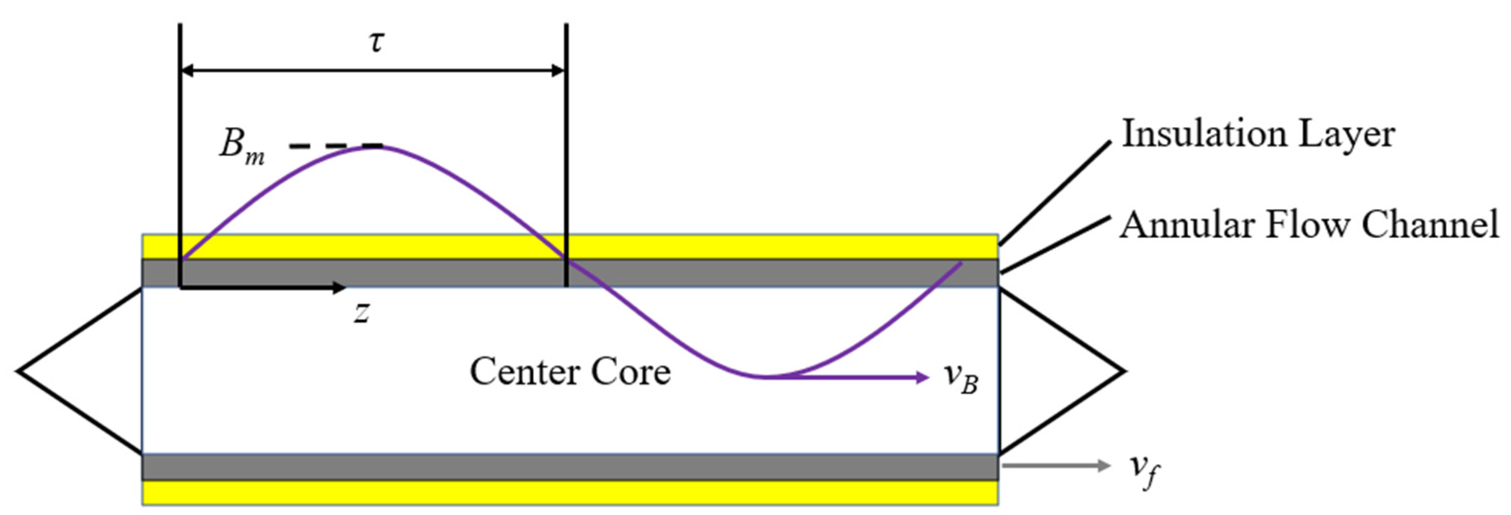
2.2. Flow-Head Model

The annular linear induction pump designed in this study features a cylindrical symmetrical structure, and the internal magnetic field distribution is shown in Figure 4. When the three-phase alternating current is applied, the center core of the EMP generates a traveling magnetic field in the direction of the flow channel through electromagnetic induction. This creates a closed magnetic circuit across the external core, annular flow channel, liquid lead–bismuth, and central core. The liquid lead–bismuth within the annular flow channel passively intercepts the magnetic flux lines under the influence of the traveling magnetic field, generating induced currents. These currents, through Lorentz forces, drive the flow of the liquid lead–bismuth.
In the magnetic field inside the electromagnetic pump, the magnetic flux density amplitude Bm can be calculated with the following formula:
B m = 1.35 μ 0 N k w I ϕ d a i r g a p p
Figure 5 shows the magnetic field distribution within the annular flow channel during the operation of the EMP. As shown in the figure, the instantaneous magnetic field intensity along the flow channel in the z-direction is given by the following equation [22]:
B z = B m sin ( ω t π z / τ )
The induced electromotive force Ez generated by the electromagnetic pump at position z is given in Equation (28).
E z = B z L v R = B m sin ( ω t π z / τ ) π D a n n u l a r ( v s y n v f )
The induced current Iz generated by the dz segment at position z is given in Equation (29).
I z = B z v R d a n n u l a r r L B E d z
The Ampere force dF exerted on the liquid lead–bismuth in the segment dz is given in Equation (30).
d F = B z I z L s t a t o r = B z 2 L s t a t o r v R d a n n u l a r r L B E d z
After a complete cycle, the Ampere force Fp exerted on the liquid lead–bismuth in the EMP can be calculated with Equation (31).
F p = d F = L s t a t o r v R d a n n u l a r r L B E B m 2 τ
The Ampere force causes a pressure difference in the annular flow channel. The pressure difference ΔP between the inlet and outlet of the EMP is given in Equation (30) [14].
Δ P = F P P A a n n u l a r = 2 B m 2 L s t a t o r 2 r L B E π ( D j + D a n n u l a r ) ( v s y n v f )
Taking into account the total pressure loss caused by gravity pressure drop, friction pressure drop, and form resistance pressure drop to the pressure measuring points at both ends of the EMP, the pressure drop correction factor ∆PM is introduced:
Δ P M = Δ P f + Δ P e l + Δ P c
where ∆Pf is the friction pressure drop of liquid LBE flowing in the flow channel, ∆Pel is the gravity pressure drop caused by the height difference of the pressure measuring point, and ∆Pc is the form resistance pressure drop caused by the sudden expansion and contraction of the pipeline at both ends of the pump.
The final experimentally measured pressure difference between the inlet and outlet of the EMP can be expressed as follows:
Δ P = 2 B m 2 L s t a t o r 2 r L B E π ( D j + D a n n u l a r ) ( v s y n v f ) + Δ P M

3. Design and Manufacturing

The development and manufacturing process of the electromagnetic pump is illustrated in Figure 6. The process begins with the determination of the pumping medium and performance requirements, which guide the selection of key parameters for the pump. These parameters are categorized into hydraulic, electrical, and structural aspects, each critical for the optimal design of the pump. Following this, the design and fabrication of key components are carried out, ensuring the integration of all necessary functionalities. Once the components are prepared, the electromagnetic pump is assembled as a whole unit. Finally, comprehensive performance testing and verification are conducted to assess the pump’s operational characteristics and ensure that it meets the specified requirements. This structured approach ensures that each step is carefully considered and validated, leading to the development of a high-performance electromagnetic pump. Figure 7 shows a schematic of the three-dimensional structure of the EMP designed in this study. The total length of it is about 1300 mm. The cross section of the EMP is a regular hexagon with a side length of 225 mm and a side distance of 400 mm.
Different liquid metal flow media, such as sodium, sodium–potassium alloy, and lead–bismuth eutectic (LBE), exhibit varying electrical conductivity and chemical properties, which require distinct structural designs and material selections for the pump body. The EMP designed in this study is specifically intended to drive liquid LBE, which is highly corrosive. Consequently, low-carbon austenitic stainless steel, renowned for its corrosion resistance, is selected as the primary material for the pump’s structural components. Moreover, compared to liquid sodium, liquid LBE has a higher density and lower electrical conductivity. As a result, the EMP designed for liquid LBE necessitates a more compact design to concentrate the magnetic field within the pump body, ensuring a stable driving force. Once the type of pumped fluid and the performance requirements of the EMP are determined, the subsequent steps for parameter design and manufacturing should be carried out, as discussed below.

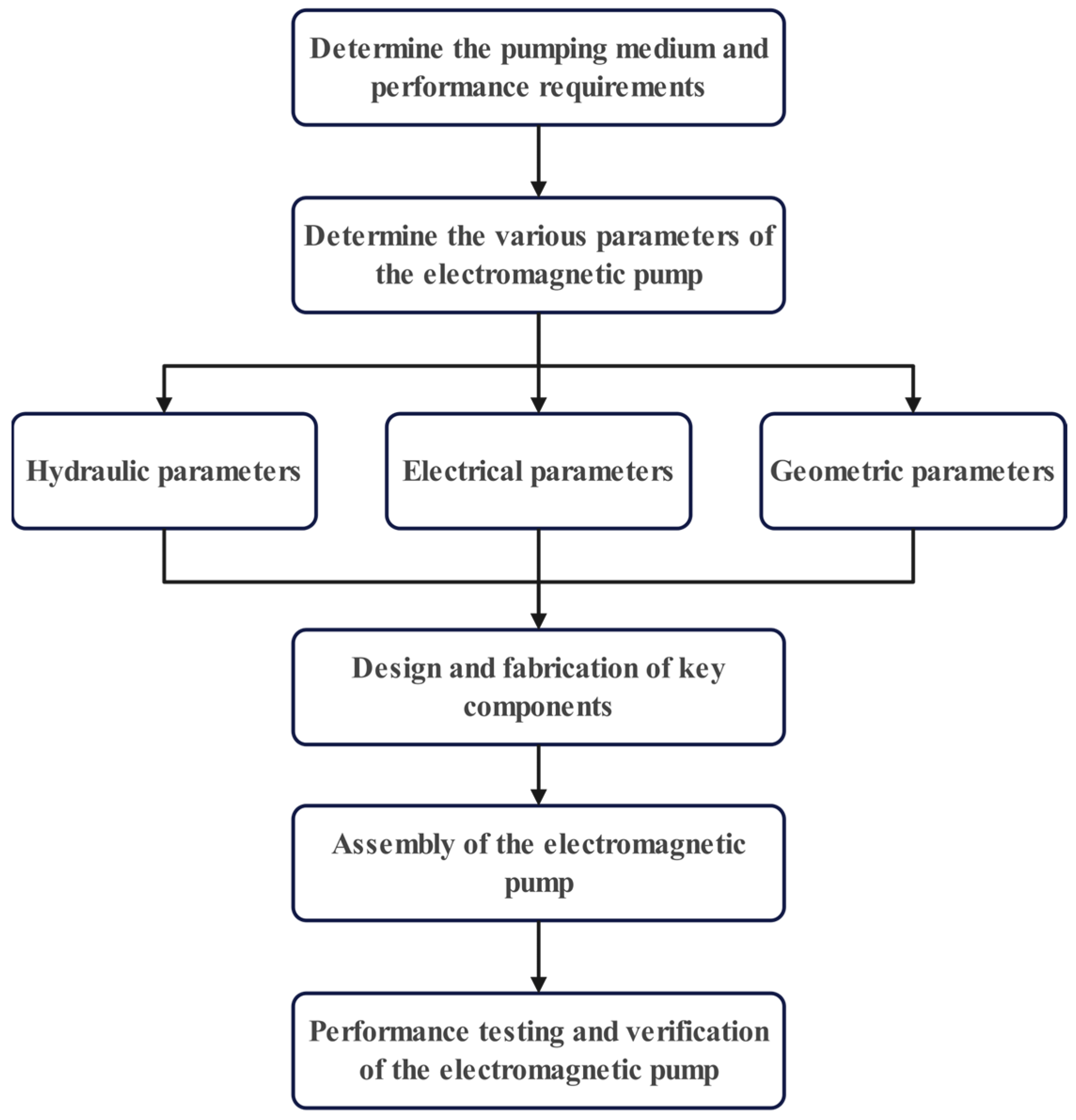
3.1. Parameter Design of the EMP

The parameter design of the EMP primarily includes the following aspects:
(1)
Hydraulic parameter design: This involves the flow rate range and driving head for the EMP.
(2)
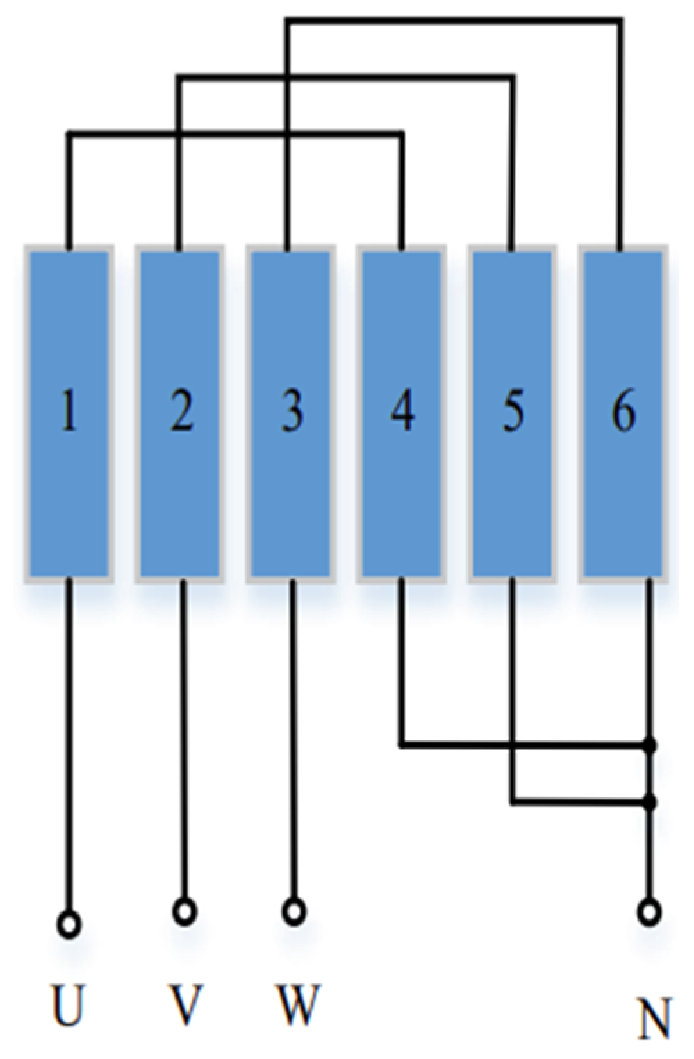
Electrical parameter design: This involves the input current range, rated voltage, rated frequency, pole pair number, and winding connection method.
(3)
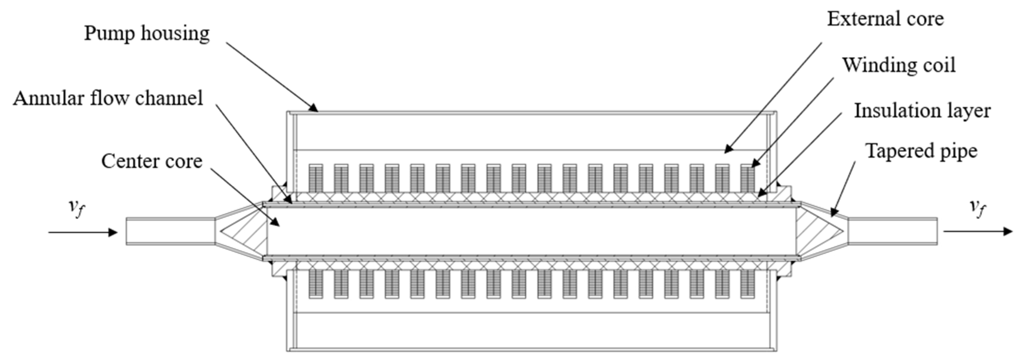
Geometric parameter design: This includes the dimensions of the annular flow channel, as well as the center and external iron cores and the solenoid coil.
The design principles and related parameters for the EMP developed in this study are outlined below.

3.1.1. Hydraulic Parameter Design

The developed EMP is primarily intended to drive liquid lead–bismuth alloy in the experimental system loop. Consequently, the hydraulic parameters of the EMP must be designed based on the flow limits of the liquid LBE in the pipeline. Liquid LBE is highly corrosive and can cause intergranular corrosion of the stainless steel pipe walls during flow, thereby weakening the pipes. Consequently, the flow speed of liquid LBE inside stainless steel pipes is typically controlled to stay below 2 m/s to mitigate the corrosive effects on the pipe walls [22]. The pipeline carrying the EMP has an inner diameter of 38 mm, an outer diameter of 45 mm, and a wall thickness of 3.5 mm. To maintain the liquid LBE flow speed within 2 m/s, the electromagnetic pump’s output flow rate should be controlled within the range of 0 to 8 m3/h. Additionally, with the experimental setup having an overall height of 5 m, the head of the developed EMP should be more than 5 m. In summary, the hydraulic parameter design for the EMP is as follows (Table 1):

3.1.2. Electrical Parameter Design

The EMP operates on a principle analogous to that of a three-phase asynchronous motor. In a three-phase asynchronous motor, the number of poles corresponds to the number of north (N) and south (S) magnetic poles generated by the winding coils. For a six-slot motor, with a phase sequence of AZBXCY for the three-phase alternating current, two magnetic poles are formed, creating one pole pair. This configuration generates a traveling magnetic field that varies sinusoidally in the liquid metal flow channel, thereby propelling the fluid forward. The three-phase alternating current is connected in a Y configuration, as illustrated in Figure 8 below:
To ensure that the developed EMP achieves a sufficiently high driving head, the pump is designed and manufactured with an 18-slot configuration and three pole pairs. As the number of pole pairs increases, the driving capacity of the EMP is increased accordingly. The wiring configuration of the 18-slot annular channel linear induction electromagnetic pump is illustrated in Figure 9 below:
The remaining electrical parameters are shown in Table 2 below:

3.1.3. Geometric Parameter Design

For an annular channel linear induction electromagnetic pump, the stronger the magnetic field of the winding coils, the greater the electromagnetic force generated per unit volume of liquid metal. The magnetic field strength of the winding coils inside the annular channel is inversely related to the air gap width. The larger the air gap, the less concentrated the magnetic flux in the annular channel, resulting in a weaker magnetic field. Additionally, a larger air gap increases the amount of magnetic flux leakage, leading to lower efficiency of the electromagnetic pump. Therefore, in the design of the electromagnetic pump, the air gap width must be minimized. Figure 10 shows the internal structure of the EMP. The air gap between the winding coils and the center core is composed of the following parts: the stainless steel protective layer of the center core, the annular flow channel, the outer wall of the annular channel, the insulation layer, and the air layer.
Based on these design principles, the geometric parameters of each structural component of the electromagnetic pump are listed in Table 3 below:

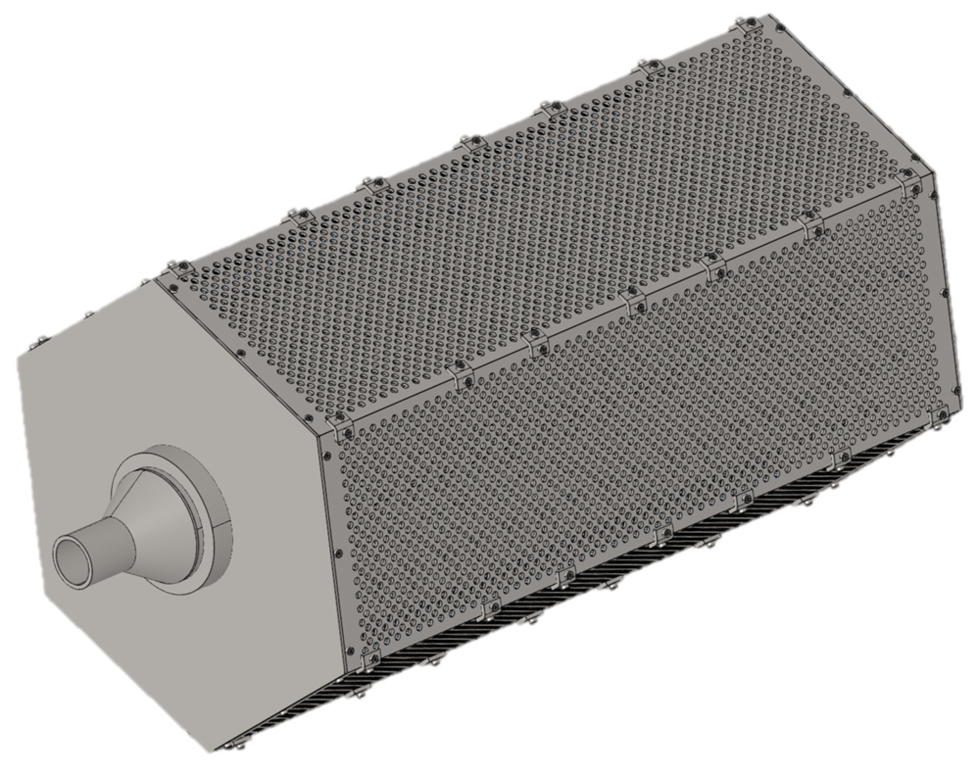
3.2. Fabrication and Manufacturing of the EMP

Based on the parameter design of the electromagnetic pump, the fabrication and manufacturing of its structural components mainly involve the fabrication of electromagnetic coils, the external core (toothed silicon steel sheets), the center core, and the pump housing. The electromagnetic coils are key components responsible for electromechanical energy conversion, making them crucial components of the electromagnetic pump. The coils can consist of single or multiple turns, with each turn made up of several conductors. The design of the windings must meet the following conditions: they must generate sufficient induced electromotive force while allowing sufficient current flow through the windings to produce the required electromagnetic torque and power. In an ALIP structure, enameled flat copper wire is typically used. The copper wire is wound into annular winding coils and fixed in the slots of the toothed silicon steel sheets of the external core. In addition to the electromagnetic coils, the design and manufacturing of the inner and outer iron cores are also crucial in the development of the electromagnetic pump. During operation, the inner and outer iron cores work together to form a closed magnetic circuit, ensuring that the magnetic field generated by the electromagnetic coils is effectively concentrated and directed into the annular channel where the fluid resides. Additionally, it enhances the efficiency of electromagnetic induction with the conductive fluid, thereby improving the pump’s efficiency and fluid delivery capability. The iron cores are usually made by stacking cold-rolled, non-oriented silicon steel sheets with small thickness, minimizing energy losses due to eddy currents and improving the overall efficiency of the electromagnetic pump.
After completing the fabrication of the structural components, the pump undergoes full assembly and integration. This process includes the following:
(1)
Securing the center core to the inner wall of the annular channel;
(2)
Fixing the inner and outer walls of the annular channel;
(3)
Installing insulation layers on the outer surface of the annular channel;
(4)
Installing and securing the external core;
(5)
Winding and fixing the coils;
(6)
Installing the pump casing.
The final integrated EMP is shown in Figure 11.

4. Experiments and Results

4.1. Experimental Loop

Performance testing of the developed EMP was conducted using the lead–bismuth thermal hydraulic experimental loop. The schematic diagram of the system is shown in Figure 12. The lead–bismuth flow primary loop, the oil cooling loop, and the gas loop are part of the experimental loop. The lead–bismuth primary loop includes components such as a lead storage tank, a preheater, a heater, a heat exchanger, a buffer tank, the electromagnetic pump, and an electromagnetic flowmeter. The oil cooling loop consists of equipment such as a thermal oil tank and a thermal oil pump. The gas loop contains an argon cylinder, a gas buffer tank, and a vacuum pump. The basic design parameters and operating parameters of the experimental loop are shown in Table 4.
Table 5 presents a list of the measuring instruments in the experimental loop and their accuracy. The measurement uncertainty mainly arises from instrument measurement error and data acquisition error. The total uncertainty can be expressed by the following correlation [14]:
u t = u m 2 + u d 2

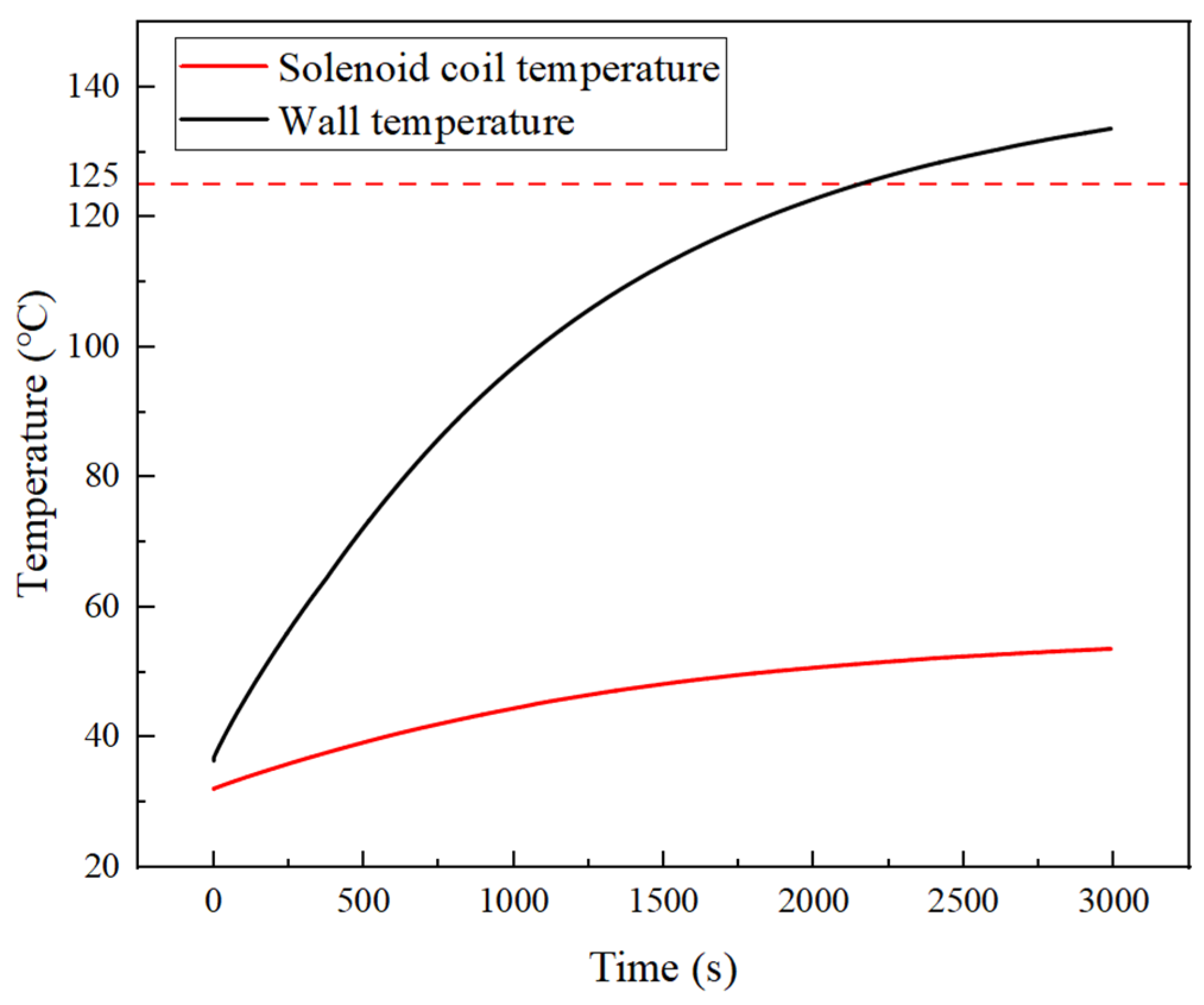
4.2. Start-Up and Preheating Characteristics

The melting point of LBE under atmospheric pressure is 125 °C. When the temperature drops below its melting point, the liquid LBE rapidly solidifies on the inner walls of the annular channel, which causes blockage of the flow channel and affects the performance of the pump. Therefore, prior to conducting lead-in experiments with the electromagnetic pump, the internal annular channel must be preheated to above 125 °C. When the electromagnetic pump is started, the electromagnetic coils generate a magnetic field that induces eddy currents in the silicon steel sheets of the center core and the inner wall of the annular channel. In this way, the EMP can achieve self-heating. To monitor the internal temperature of the EMP, two temperature measurement points were installed to measure the temperature of the annular channel wall and the electromagnetic coil, as shown in Figure 13. After starting the EMP, the user should increase its input current and record the temperature of the inner wall of the annular channel and the electromagnetic coil. When the temperature of the inner wall of the annular channel reaches 125 °C, the EMP developed in this study can be considered to meet the experimental requirements.
Through the start-up and preheating experiments of the EMP, the temperature variation curves of the coil temperature and inner wall temperature during the preheating process were obtained, as shown in Figure 14. It can be observed that the developed EMP has a self-heating capability. With an input current of 40 A, the inner wall temperature rises with time and reaches around 133 °C after approximately 3000 s, meeting the requirements for the experiment. Upon completion of the preheating process, the temperature of electromagnetic coils stabilizes at approximately 70 °C, which is well within the allowable temperature range (180 °C). The temperature rise of the inner wall of the annular channel gradually slows down over time, which is due to the thermal dissipation from the external environment. During the self-heating process of the EMP, the cooling fan should be turned off to minimize the impact on the internal temperature.

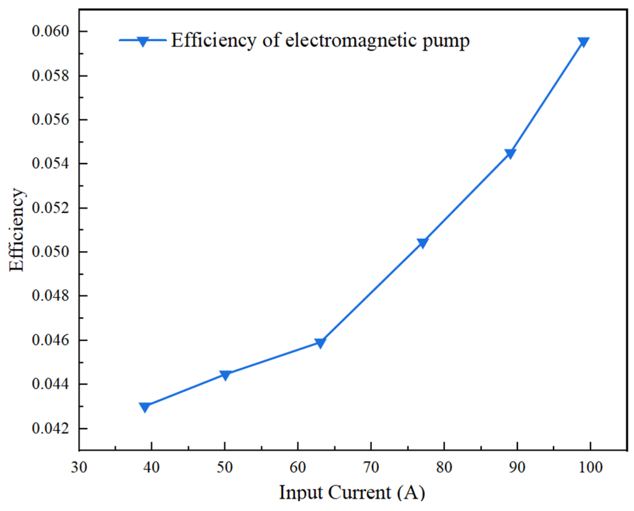
4.3. Drive Performance Characteristics

To obtain the performance parameters of the developed EMP, performance testing experiments were conducted. After starting the loop, the input current of the EMP was adjusted, gradually increasing the flow rate of LBE in the loop from 3 m3/h to 8 m3/h. The phase current and phase voltage of the EMP were recorded at different flow rates. The flow rate vs. current curve was obtained and shown in Figure 15. From the figure, it can be seen that the output flow rate of the electromagnetic pump increases with the input current. When the input current reaches 99 A, the pump achieves its maximum flow rate of 8 m3/h. Furthermore, the output flow rate is roughly proportional to the input current, aligning well with theoretical predictions.
The efficiency calculation formula for a three-phase asynchronous motor is given in Equation (10). The efficiency curve of the EMP at different input currents was obtained and shown in Figure 16. It can be seen that the efficiency of the EMP increases with the input current, reaching a maximum of 5.96% at an input current of 99 A. According to motor theory, the efficiency of a three-phase asynchronous motor increases with load (peaking when the load is between 0.7 and 1.0). Therefore, the developed EMP has not yet reached its peak efficiency. The operational efficiency of the pump falls within the rising segment of the motor’s efficiency curve, indicating that the motor is operating closer to its optimal working point. This design enables the EMP to better adapt to varying loads: as the load increases, the pumping efficiency gradually improves, allowing the pump to maintain low operational losses while accommodating a wider range of working loads.
η = Q v Δ P 3 U I cos φ

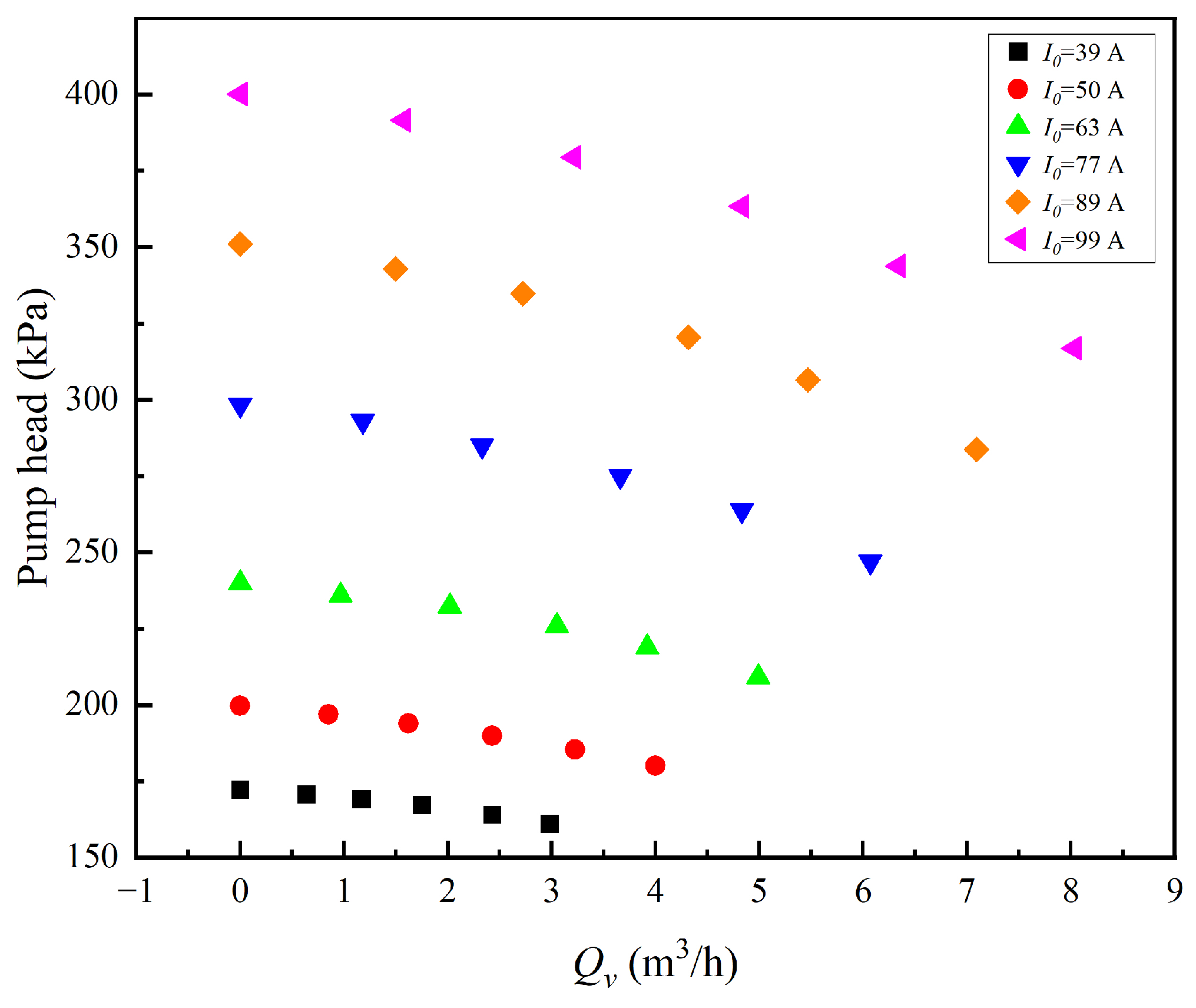
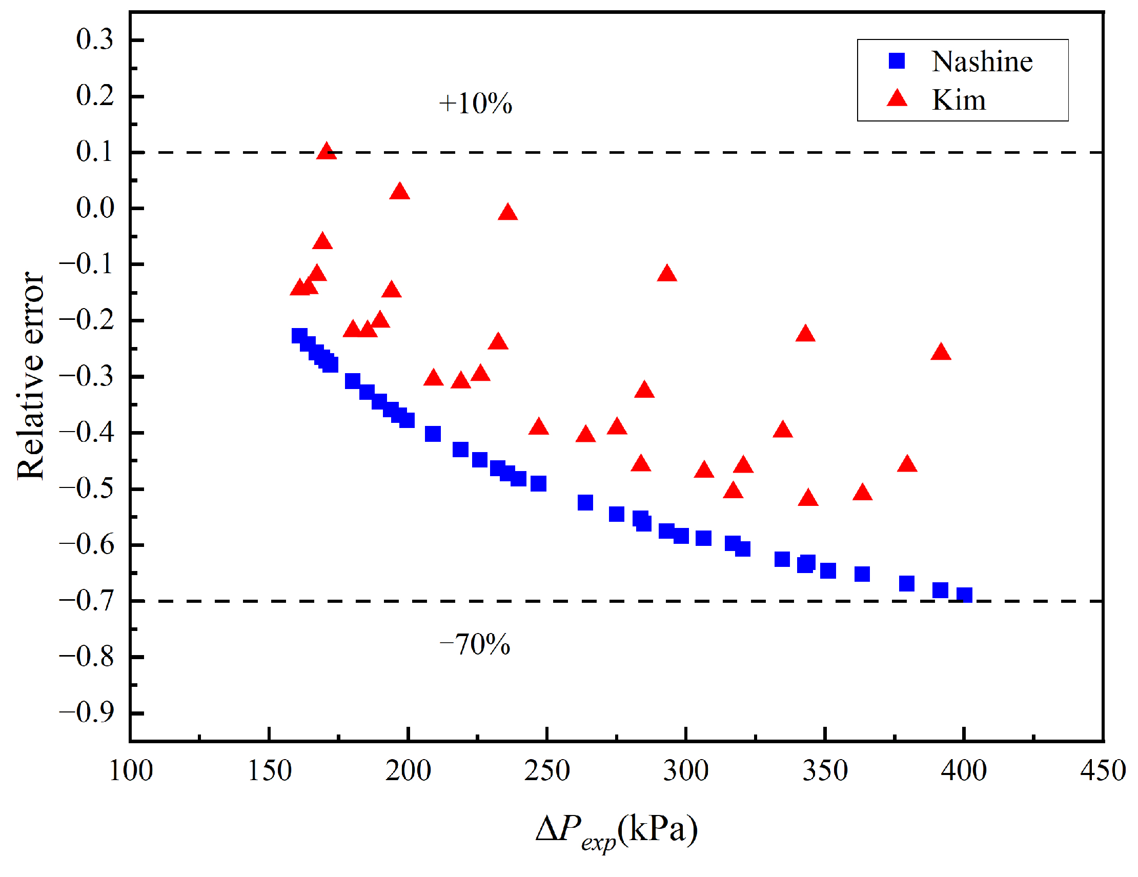
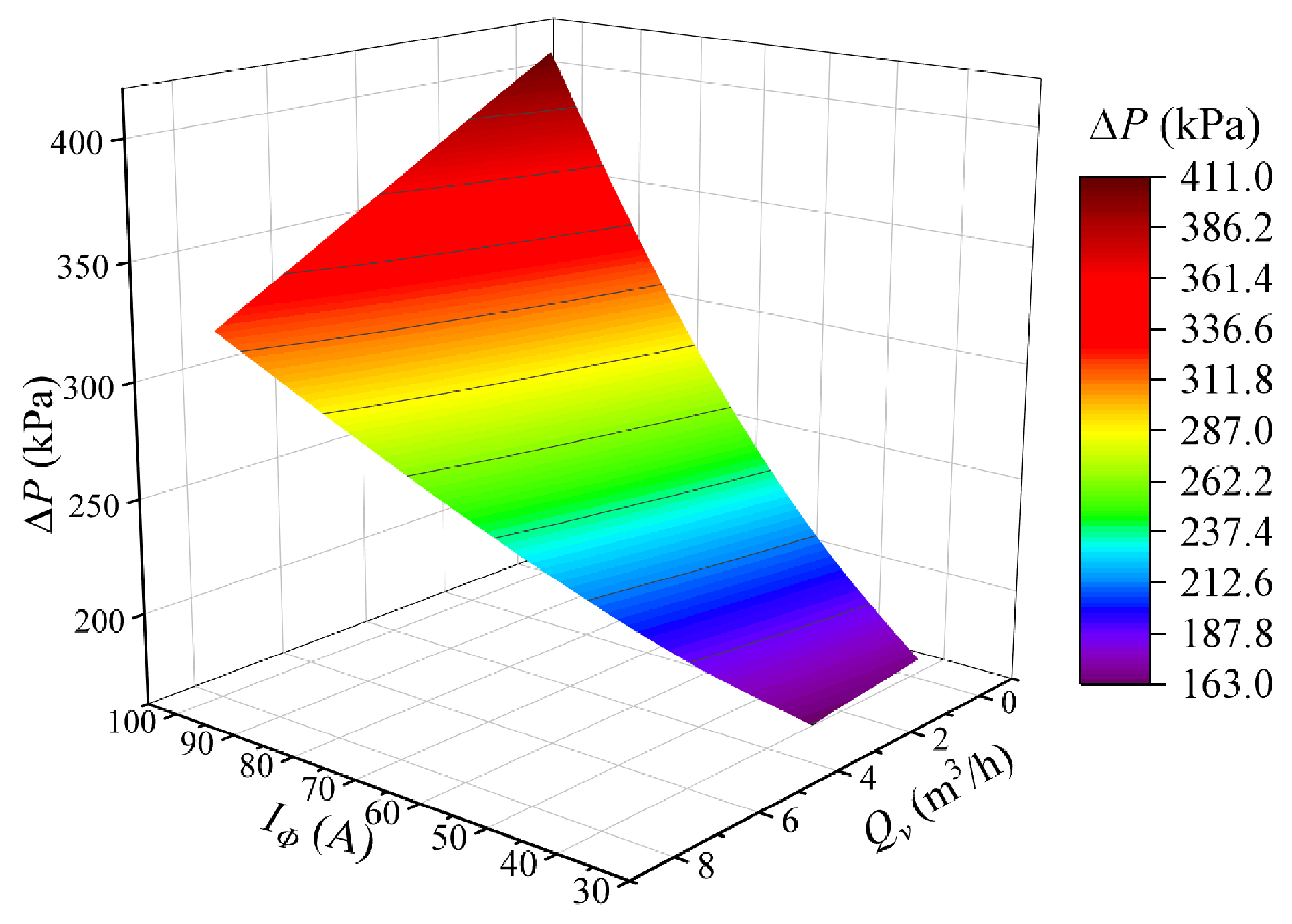
4.4. Flow Rate and Head Characteristics

To obtain the flow rate and head characteristics of the EMP and to provide an experimental basis for performance analysis and design optimization, flow rate and head characteristic experiments were conducted. After starting the loop, the input current of the EMP was fixed, and the flow rate of LBE was altered by adjusting the valve opening in the experimental loop. The experiment was repeated under different input current conditions to obtain the relationship between the flow rate and head of the EMP. The specific experimental process is illustrated in Figure 17.
Through the flow rate and head characteristic experiments of the EMP, the P–Q relationship shown in Figure 18 was obtained. It can be observed that when the input current is 99 A, the maximum driving head of the electromagnetic pump reaches 400 kPa.
Nashine et al. proposed the following ALIP theoretical flow-head model [10]:
Δ P = 2 p 1 2 p + 1 m s E A 2 r L B E Q s y n
EA is the induced electromotive force. It can be described as follows:
E A = B m π D a n n u l a r v s y n N s c k p k d 2
Kim et al. proposed the following model [11]:
Δ P = 3 I 2 Q v R 2 ( 1 s ) s ( R 2 2 / X m 2 s 2 + 1 )
where R2 is the secondary equivalent resistance. It can be described as follows:
R 2 = 6 π D ρ r k w N 2 τ p
where D is the mean diameter of the fluid, ρr is the surface electrical resistivity of the fluid, kw is the winding factor.
Figure 19 shows the relative errors between the theoretical predictions and experimental values of the above two models. It can be seen from the figure that the data predicted by the models are smaller, with the maximum error reaching 70%. Kim’s and Nashine’s models are derived based on the conditions of liquid sodium working fluid. Therefore, their theoretical method may cause a large error in the prediction of the developed EMP head in this study.
The deviations between the calculated and experimental values are compared in conjunction with the theoretical model. As shown in Figure 20, a significant deviation remains. This is due to the unpredictable eddy currents generated by the liquid LBE in the pump and the stainless steel pipeline under the influence of the magnetic field during the operation of the EMP. End effects cause non-uniform magnetic field distribution at the pump inlet and outlet. Eddy current loss and end effects affect the performance of the EMP. Additionally, the frequency fluctuation of the power supply and the disturbance of the electromagnetic flowmeter significantly affect the measured values. Therefore, to address these issues, the head correction coefficient c1, frequency correction coefficient c2, and flow correction coefficient c3 are introduced for correction:
Δ P = c 1 B m 2 L s t a t o r 2 r L B E π ( D j + D a n n u l a r ) ( c 2 v s y n c 3 v L B E )
By fitting to the experimental results, c1 = 5.9, c2 = 0.9, and c3 = 1.25 were determined. The fitted relationship is compared with the experimental data as shown in Figure 21. Figure 22 shows the predicted values of the developed pressure under different flow rates and input currents. The relative error between the theoretical and the experimental values is shown in Figure 23. The calculated values are in good agreement with the experimental data, and the model prediction error is within ±5%.
The derived relationship can be used to predict the flow-head characteristics of a small lead–bismuth electromagnetic pump operating at a power frequency of 50 Hz and a flow range of 0–10 m3/h.

5. Conclusions

This paper derives a theoretical model of a lead–bismuth alloy annular linear induction pump based on the equivalent circuit method. A pump with a flow rate of 8 cubic meters per hour and a head of 500 kPa was designed and developed based on the principles of EMPs. A startup preheating experiment, a performance testing experiment, and a set of flow-head experiments for the EMP were conducted based on the lead–bismuth thermal hydraulic experimental loop. The experimental results show the following: (1) The annular channel can be heated to 133 °C within 3000 s, and the coil temperature is controlled below 70 °C. (2) The output flow rate increases with the increase in input current of the EMP. When the input current is 99 A, the maximum flow rate of the EMP is 8 m3/h, and the efficiency is 5.96% at this time. (3) Through the flow-head characteristic test experiment, the flow-head relationship of the EMP developed in this study was obtained and compared with the theoretical results. The flow-head model corrected by the experimental value is as follows:
Δ P = c 1 B m 2 L s t a t o r 2 r L B E π ( D j + D a n n u l a r ) ( c 2 v s y n c 3 v L B E )
where the head correction coefficient c1 = 5.9, the frequency correction coefficient c2 = 0.9, and the flow correction coefficient c3 = 1.25. The obtained relationship can be used to predict the flow-head relationship of a small lead–bismuth electromagnetic pump with a power frequency of 50 Hz and a flow range of 0–10 m3/h.

Author Contributions

Z.L.: writing—original draft, formal analysis. L.Y.: writing—review & editing, investigation. C.W.: writing—review & editing; S.Q.: supervision, methodology, visualization. Y.L.: funding acquisition, resources, validation. All authors have read and agreed to the published version of the manuscript.

Funding

This study is financially supported by the Innovative Scientific Program of CNNC. This study is also supported by the Sichuan Science and Technology Program (grant 2023NSFSC1314).

Data Availability Statement

The original contributions presented in this study are included in the article. Further inquiries can be directed to the corresponding author.

Conflicts of Interest

The authors declare that they have no known competing financial interests or personal relationships that could have appeared to influence the work reported in this paper.

Nomenclature

Aannular (m2)Sectional area of annular flow channelL2 (H)Inductance at airgap
AB (m2)Magnetic area of EMPLB (m)Magnetic circuit length
Acoil (m2)Cross-sectional area of a single winding coilLcoil (m)Length of coil
Bm (T)Magnetic density amplitudeLstator (m)Stator length
BP (T)Magnetic density of single stageMNumber of phases
Bz (T)Magnetic density at zNTurns of coil
dairgap (m)Air layer thicknessNscEffective number of turns in series per phase in stator
dannular (m)Annular channel widthΔP (kPa)Pump head
dcoil (m)Winding coil widthpPole pairs
dw,in (m)Annular channel inner wall thicknessPM (kPa)Pressure drop correction factor
dw,out (m)Annular channel outer wall thicknessPf (kPa)Friction pressure drop
D0 (m)Diameter of center corePel (kPa)Gravity pressure drop
Dair (m)Air layer outer diameterPc (kPa)Form resistance pressure drop
Dannuluar (m)Annular channel outer diameterQNumber of slots
Dcoil (m)Winding coil radial lengthQv (m3/h)Volume flow rate
Dj (m)Insulation layer outer diameterQsyn (m3/h)Synchronous volume flow rate
EA (V)Induced electromotive forceqNumber of slots per pole pair in a phase
EB (V)Total induced electromotive forcerCuResistivity of Cu
Ez (V)Induced electromotive force at zrLBEResistivity of LBE
F1 (H)Fundamental wave MMF of single-phase windingrssResistivity of stainless steel
F3 (H)Fundamental wave MMF of three-phase windingR1 (Ω)Primary equivalent resistance
Fm (H)MMF amplitudeR2 (Ω)Secondary equivalent resistance
Fp (N)Ampere forceRcoil (Ω)Resistance of coil
Ge (m)Effective inter-core gapsSlip
H (T)Magnetic field strengthTCu (°C)Temperature of copper coil
Iφ (A)Phase currentTLBE (°C)Temperature of LBE
Iz (A)Induced current generated by dzt (s)Time
iφ (A)Instantaneous phase currentU (V)Input voltage
kwWinding factorvsyn (m/s)Synchronous speed
kfSlot-filling factorvf (m/s)Fluid velocity
kdWinding distribution factorvR (m/s)Relative speed
KpPitch factorX1 (Ω)Equivalent leakage reactance
L (H)Total inductance of winding coilXm (Ω)Magnetizing reactance
L1 (H)Inductance at coil
Greek symbols
μ0Vacuum permeabilityτ (m)Pole distance
ηEfficiencyρcResistivity of coil conductor
ρrSurface electrical resistivity of fluidωInput angular frequency
λckd(1 + 3a)/12 (a: chording factor)ΦMagnetic flux

References

  1. U.S. DOE. A Technology Roadmap for Generation IV Nuclear Energy System. In Nuclear Energy Research Advisory Committee and the Generation IV International Forum; U.S. DOE: Washington, DC, USA, 2002. [Google Scholar]
  2. Tuček, K.; Tsige-Tamirat, H.; Ammirabile, L.; Lázaro, A.; Grah, A.; Carlsson, J.; Döderlein, C.; Oettingen, M.; Fütterer, M.; D’agata, E.; et al. Generation IV Reactor Safety and Materials Research by the Institute for Energy and Transport at the European Commission’s Joint Research Centre. Nucl. Eng. Des. 2013, 265, 1181–1193. [Google Scholar] [CrossRef]
  3. Dong, Z.; Qiu, H.; Wang, M.; Tian, W.; Qiu, S.; Su, G. Numerical simulation on the thermal stratification in the lead pool of lead-cooled fast reactor (LFR). Ann. Nucl. Energy 2022, 174, 109176. [Google Scholar] [CrossRef]
  4. Stanisz, P.; Oettingen, M.; Cetnar, J. Monte Carlo modeling of Lead-Cooled Fast Reactor in adiabatic equilibrium state. Nucl. Eng. Des. 2016, 301, 341–352. [Google Scholar] [CrossRef]
  5. Gluekler, E.L. US advanced liquid metal reactor (ALMR). Prog. Nucl. Energy 1997, 31, 43–61. [Google Scholar] [CrossRef]
  6. Baker, R.S.; Tessier, M.J. Handbook of Electromagnetic Pump Technology; Elsevier: Amsterdam, The Netherlands, 1987. [Google Scholar]
  7. Childs, B.M. Electromagnetic pumps and flowmeters for fast-reactor development. Ann. Nucl. Sci. Eng. 1974, 1, 351I–357I. [Google Scholar] [CrossRef]
  8. Blake, L.R. Conduction and induction pumps for liquid metals. Proc. IEE-Part A Power Eng. 1957, 104, 49–67. [Google Scholar] [CrossRef]
  9. Kikuchi, K.; Kurata, Y.; Saito, S.; Futakawa, M.; Sasa, T.; Oigawa, H.; Wakai, E.; Miura, K. Corrosion–erosion test of SS316 in flowing Pb–Bi. J. Nucl. Mater. 2003, 318, 348–354. [Google Scholar] [CrossRef]
  10. Ota, H.; Katsuki, K.; Funato, M.; Taguchi, J.; Fanning, A.W.; Doi, Y.; Nibe, N.; Ueta, M.; Inagaki, T. Development of 160 m3/min large capacity sodium-immersed self-cooled electromagnetic pump. J. Nucl. Sci. Technol. 2004, 41, 511–523. [Google Scholar] [CrossRef]
  11. Sharma, P.; Sivakumar, L.; Prasad, R.R.; Saxena, D.; Kumar, V.S.; Nashine, B.; Noushad, I.; Rajan, K.; Kalyanasundaram, P. Design, development and testing of a large capacity annular linear induction pump. Energy Procedia 2011, 7, 622–629. [Google Scholar] [CrossRef]
  12. Nashine, B.K.; Rao, B. Design, in-sodium testing and performance evaluation of annular linear induction pump for a sodium cooled fast reactor. Ann. Nucl. Energy 2014, 73, 527–536. [Google Scholar] [CrossRef]
  13. Kim, H.R.; Kwak, J.S. MHD design analysis of an annular linear induction electromagnetic pump for SFR thermal hydraulic experimental loop. Ann. Nucl. Energy 2016, 92, 127–135. [Google Scholar] [CrossRef]
  14. Wang, L.; Hou, Y.; Shi, L.; Wu, Y.; Tian, W.; Song, D.; Qiu, S.; Su, G. Experimental study and optimized design on electromagnetic pump for liquid sodium. Ann. Nucl. Energy 2019, 124, 426–440. [Google Scholar] [CrossRef]
  15. Pan, W.; Chen, X.; Wang, X. Generalized design method of the three-phase Y-connected wound rotor for both additive modulation and differential modulation brushless doubly fed machines. IEEE Trans. Energy Convers. 2021, 36, 1940. [Google Scholar] [CrossRef]
  16. Zhang, Z.; Liu, H.; Song, T.; Zhang, Q.; Yang, L.; Bi, K. One dimensional analytical model considering end effects for analysis of electromagnetic pressure characteristics of annular linear induction electromagnetic pump. Ann. Nucl. Energy 2022, 165, 108766. [Google Scholar] [CrossRef]
  17. Nasar, S.A. Linear Motion Electric Machines; John Wiley & Sons: New York, NY, USA, 1976. [Google Scholar]
  18. Matula, R.A. Electrical resistivity of copper, gold, palladium, and silver. J. Phys. Chem. Ref. Data 1979, 8, 1147–1298. [Google Scholar] [CrossRef]
  19. Roman, C.R. Study of the Electromagnetic Pumping Systems of Molten Metals and Molten Salts. Ph.D. Thesis, University Grenoble, Grenoble, France, 2014. [Google Scholar]
  20. NEA. Handbook on Lead-Bismuth Eutectic Alloy and Lead Properties, Materials Compatibility, Thermal-hydraulics and Technologies, 2007 ed.; OECD Publishing: Paris, France, 2007. [Google Scholar]
  21. Yan, J.C. Electrical Machinery; Press of University of Science and Technology of China: Hefei, China, 2013. (In Chinese) [Google Scholar]
  22. Tarantino, M.; Angiolini, M.; Bassini, S.; Cataldo, S.; Ciantelli, C.; Cristalli, C.; Del Nevo, A.; Di Piazza, I.; Diamanti, D.; Eboli, M.; et al. Overview on Lead-Cooled Fast Reactor Design and Related Technologies Development in ENEA. Energies 2021, 14, 5157. [Google Scholar] [CrossRef]
Figure 1. Classification of electromagnetic pumps.
Energies 18 00750 g001
Figure 2. Equivalent circuit model of electromagnetic pump.
Energies 18 00750 g002
Figure 3. Equivalent leakage reactance in the electromagnetic pump.
Energies 18 00750 g003
Figure 4. Schematic diagram of magnetic field distribution inside the electromagnetic pump.
Energies 18 00750 g004
Figure 5. Schematic diagram of annular flow channel.
Energies 18 00750 g005
Figure 6. Flow diagram of the development and manufacturing process of the electromagnetic pump.
Energies 18 00750 g006
Figure 7. Three-dimensional design of the electromagnetic pump.
Energies 18 00750 g007
Figure 8. Schematic diagram of star connection method.
Energies 18 00750 g008
Figure 9. Wiring diagram of 18-slot electromagnetic pump.
Energies 18 00750 g009
Figure 10. Schematic diagram of the internal structure of the EMP.
Energies 18 00750 g010
Figure 11. The electromagnetic pump developed in this study.
Energies 18 00750 g011
Figure 12. Schematic diagram of lead–bismuth thermal hydraulic experimental loop.
Energies 18 00750 g012
Figure 13. Layout diagram of temperature measurement points for the EMP.
Energies 18 00750 g013
Figure 14. Preheating curve of the EMP.
Energies 18 00750 g014
Figure 15. Flow vs. current variation curve of the EMP.
Energies 18 00750 g015
Figure 16. Efficiency curve of electromagnetic pump.
Energies 18 00750 g016
Figure 17. Flowchart of experimental procedure.
Energies 18 00750 g017
Figure 18. Flow and head experimental data.
Energies 18 00750 g018
Figure 19. Existing model versus test data.
Energies 18 00750 g019
Figure 20. Theoretical model versus test data.
Energies 18 00750 g020
Figure 21. Fitted theoretical model versus test data.
Energies 18 00750 g021
Figure 22. Developed pressure under different flow rates and input currents.
Energies 18 00750 g022
Figure 23. Relative error of the fitted theoretical model.
Energies 18 00750 g023
Table 1. Design table of hydraulic parameters for EMP.
Design VariablesUnitsValues
Flow rate (Q)m3·h−18
Developed pressure (ΔP)kPa500
Table 2. Design table of electrical parameters for electromagnetic pump.
Design VariablesUnitValues
Input voltage (U)V380
Input current (I)A0~150
Power frequency (f)Hz50
Number of slots-18
Number of pole pairs -3
Connection method-Y connection
Table 3. Design table of geometric parameters for electromagnetic pump.
Design VariablesUnitValues
Core length mm780
Inner core diametermm89
Flow gapmm4
Channel outer wall thicknessmm2
Insulation thicknessmm10
Air layer thicknessmm5
Tooth widthmm22
Slot widthmm22
Table 4. Experimental loop design parameters.
ParametersValue
Design operating pressure/MPa0–1.6
Design operating temperature/°C150–450
LBE capacity/kg800
Pipe material316 L
Main circuit pipe diameter/mmΦ45*3.5
Total circuit heating power/kW150
Total circuit cooling cower/kW150
Maximum flow rate of LBE/m·s−12.0
Maximum volume flow rate of LBE/m3·h−18
Volume of the storage tank/L200
Maximum pressure of the storage tank/MPa1.6
Table 5. The accuracy of the measuring instruments.
InstrumentMeasurementRangeAccuracy
EMFQv (m3/h)20±2%
Differential pressure transmitterP (kPa)800±0.075%
K-type thermocoupleT (°C)1300±0.5 K
Data acquisition system- ±0.02%
Disclaimer/Publisher’s Note: The statements, opinions and data contained in all publications are solely those of the individual author(s) and contributor(s) and not of MDPI and/or the editor(s). MDPI and/or the editor(s) disclaim responsibility for any injury to people or property resulting from any ideas, methods, instructions or products referred to in the content.

