1. Introduction
Measures taken to reduce greenhouse gas emissions in electricity generation are leading to an increased share of converter-connected and variable generation, for instance, wind and solar power, being connected to national electricity networks, along with the decommissioning of older thermal plants. The situation has increased the difficulty of frequency regulation—matching supply and demand—requiring generation and energy storage with increased flexibility and response speeds. Variable-Speed Hydropower (VSHP) aims to improve the flexibility and responsiveness of hydroelectric power plants by using a power electronic converter between the generator and grid, allowing the turbine speed to vary independently of the grid frequency.
Early VSHP installations concentrated on improving the flexibility of pumped-storage plants using Francis turbines [
1]. In the pumping mode of operation, the turbine guide vanes are kept fully open with the turbine run in reverse, and the power input from the grid is fixed due to the fixed turbine speed. Additionally, the optimum speeds for pumping and generating are different, meaning that efficiency in the generating mode is compromised. Replacing the synchronous generator with a Doubly-Fed Induction Generator (DFIG), with the rotor connected to the grid through a converter, allows a limited turbine speed variation (typically around 10% [
2]), allowing some variation in the pumping power and improved efficiency when generating. In such a system, the main economic advantage is to allow the plant to provide frequency support services during pumping operations.
Improvements in the response speed during generating operations are possible [
3] due to the decoupling of the turbine speed from the grid frequency, as grid interactions limit the stable governor bandwidth in a fixed-speed system. However, the mechanical response speed is still ultimately limited by the waterway dynamics, so variable-speed plants can take energy from the generator inertia to provide instant power, slowing down the generator. As the slower-reacting hydraulic system catches up, the turbine speed is recovered.
DFIG-based systems used for early installations [
1] employed thyristor-based cyclo-converters to limit the converter size required. Still, there is an increasing interest in using fully-rated converters [
4]. Recent studies have considered the enhancements of fully rated converters by designing new configurations [
5]. The idea of fully-rated converters was initially brought about by the development of converters with a power rating of 100 MW and higher based on the Modular Multilevel Converter (MMC), and operating at the generator voltage without the use of a step-down transformer [
6]. These are easier to retrofit to existing installations as the existing generator can be used, and the converter can be bypassed when not required to maximise efficiency. Fully-rated converter systems allow a wider variation in turbine speed, increasing the amount of inertial energy available for fast response. They can also increase the power range of the turbine during generation by reducing the turbine speed at lower power levels to avoid operating modes, which would reduce the turbine’s lifetime. DFIGs for the VSHP still attract researchers. In a recent study, some performance improvements were introduced [
7].
The existing literature on VSHP has largely concentrated on the capabilities of a fast response to changes in power demand and an enhanced operating range. Several additional benefits were considered in a number of studies. These include but are not limited to:
In some cases, the ability to compensate for varying wind farm outputs has been evaluated by directly modifying the VSHP power demand based on the measured wind farm output [
11]. Studies relating to the provision of grid frequency support services have largely concentrated on the potential revenue improvements [
12].
To explain the concept of generation inertia, a qualitative analysis of methods is shown in
Table 1. Using generator inertia has been one of the core approaches to stabilise the grid against frequency deviations. The conventional choice of method for this is the utilisation of synchronous generators. The synchronous generators enable the provision of physical inertia using the kinetic energy supplied by their rotating machinery components. Since renewable energy integration has begun to advance rapidly, it has caused a shift in generation methods, which has resulted in a lack of physical inertia in power generation mixes. Therefore, grids have been facing significant stability challenges. To tackle the problem of reduced inertia, methods of synchronous generators, VSMs, power converters, and fast frequency response have been considered. VSMs, power converters, and fast frequency response methods can provide synthetic inertia. Each method comes with its advantages and limitations, as listed in
Table 1. This research investigates the provision of synthetic inertia through the VSM and the VCC (power converter). By integrating these controllers, the proposed control framework aims to enhance grid stability.
From the control perspective, conventional strategies such as the Proportional-Integral-Derivative (PID) were considered for VSHP. In [
13], a VSHP model is developed and validated using such conventional control methods to understand the limitations brought by the hydraulic system, paving the way to implementing more sophisticated approaches like multi-variable or optimisation-based advanced controllers.
Regarding advanced controllers, Model Predictive Control (MPC) has been shown to be a promising approach for VSHP. Among the works in the literature, ref. [
14] takes a combined strategy where a linear MPC controls the VSHP by adjusting the turbine guide vane opening to maintain the reference turbine rotational speeds, and is supported by a VSM to handle deviations in the frequency through the converter. The controller also uses a Kalman filter to estimate the hydraulic system variables. Despite having similar principles, refs. [
15,
16] use a non-linear MPC approach and utilise a moving horizon estimator. The results show improved performance, faster response, and reduced rotational speed deviations.
Another well-established non-linear control approach, the sliding mode controller, was deployed by the researchers in [
17] for a VSHP. They carried out a benchmark of the approach with a traditional PID as the baseline method, and the results indicated a faster transient response. In [
7], a second-order sliding mode controller was considered to deal with the DFIG system. The problem of low-frequency oscillations was addressed in [
18] by developing a control technique that combines sliding mode control and fuzzy logic. Another second-order sliding mode controller was proposed to improve the guide vane opening and rotor regulations for frequency support in [
19].
There are other contributions from the domain of hydropower plant control in which different MPC strategies are used. Among these contributions, ref. [
20] designed a non-linear MPC and performed a Lyapunov stability analysis. The shortcomings of the conventional PID control were discussed, and a scalar MPC controller was proposed in [
21]. The benefit of the prediction of future water levels for a hydropower plant was investigated using an extended Kalman filter [
22]. The authors of [
23] employed fuzzy methods to improve the performance of an MPC. The work in [
24] proposed an intelligent MPC. However, the majority of such research follows the assumption of turbine speed syncing to the grid frequency and thus needs to pay more attention to its variability. Considering the steady rise of renewable energy technologies and even electric vehicles, it is important to provide a higher level of flexibility for the security of the future’s grids. VSHP could help the grid by providing fast frequency reserves as an ancillary service. A recent, comprehensive review of several hydropower plant models, including VSHP, was presented in [
25]. The survey also discusses the rapidness of VSHP in supporting a balanced grid frequency, which may come in handy, especially with the intermittent nature of renewables in mind. The flexibility of a real-world hydropower plant was studied, and its capacity was improved through optimisations in [
26].
VSHP is not a newly discovered technology, but has remained an underexplored research topic. However, it is gaining momentum on the course to reach its maximum potential. Some important research gaps or unresolved issues include:
Conventional PID-based turbine governor methods face limitations in dealing with variable speed systems due to frequent operating point changes. Their lack of adaptability leads to sub-optimal control performance. In other words, their need to be re-tuned frequently is not ideal for controlling VSHP.
While advanced control strategies such as MPC have shown promise, further research is needed to investigate their practical limitations. For example, their impacts on hydraulics and mechanical actuators or integration with electrical systems like fully-rated converters have been underexplored. For example, a recent paper [
19] presents a strategy to deal with the impacts of frequent opening of the guide vanes.
The limitations of DFIG systems, which are used conventionally for variable-speed installations, and the challenges in implementing their alternatives.
A lack of real-world implementations because most studies are based on simulations. More field validations are needed to further verify research results.
Few recent studies [
27] investigating the economic costs vs. benefits of VSHP exist.
There exists a lack of comparisons of VSHP with alternative solutions [
28] in terms of their ability to meet the flexibility demands of the renewable energy-rich grids.
This paper presents the findings of the project in [
29]. The figures and results used are fully adapted from the project report, which the same authors wrote. This study has developed an integrated control strategy consisting of a few control approaches to allow a VSHP based on a fully-rated converter to provide frequency support services, including fast frequency response and synthetic inertia. The list of novelties from the work and the paper includes:
Comprehensive Control Design: The proposed control strategy integrates a Frequency Support Controller (FSC), an anti-windup PID or Model Predictive Controller as the turbine governor, and a VSM/VCC for the grid-side converter, machine-side controller, and DC-link controller. As a result, not only is frequency support improved, but also fault ride-through capability is increased. Owing to the collective benefit of the controllers that make up the approach, a generalised performance enhancement for VSHP has been observed.
Large-scale System Model: The research aims to simulate a realistic hydropower model, so several hydraulic system components, electrical systems, and controllers were considered.
Thorough Validations: The control designs are validated thoroughly by considering various grid conditions, such as stiff grids and grids with power mixes that feature low inertia and high renewable penetration. The project demonstrates enhanced capabilities for primary and secondary frequency responses and synthetic inertia provision through simulations in both stiff and representative grid conditions. The results show improved stability compared to fixed-speed systems. The amount of validations extends beyond what is commonly observed in prior studies.
Use of Fully-Rated Converters: The research emphasises the implementation of fully-rated converters but diverges from prior research by implementing a Frequency Support Controller, which combines synthetic inertia with advanced damping techniques. Intense testing under diverse grid scenarios (stiff and low-inertia grids) may provide a deeper understanding of fully-rated converters’ performance for VSHPs.
Although a comprehensive control framework has been designed and validated, this research’s findings are derived from simulation studies and have not yet been tested in a real-world application. In addition to the need for implementation, economic feasibility and scalability were not particularly investigated by this study, but they impose important considerations for the bigger picture of the topic. These define some current limitations of this research. More insights into the future work will be given in the
Section 4.
The organisation of this paper is as follows:
Section 2 introduces the hydro-system models and controllers, and
Section 3 evaluates their performance using a stiff grid and representative grid model. The results presented in
Section 3 demonstrate the frequency support under grid frequency dipping and over-frequency cases, respectively. Additionally, the grid fault response is investigated.
Section 4 summarises and concludes the paper.
2. Materials and Methods
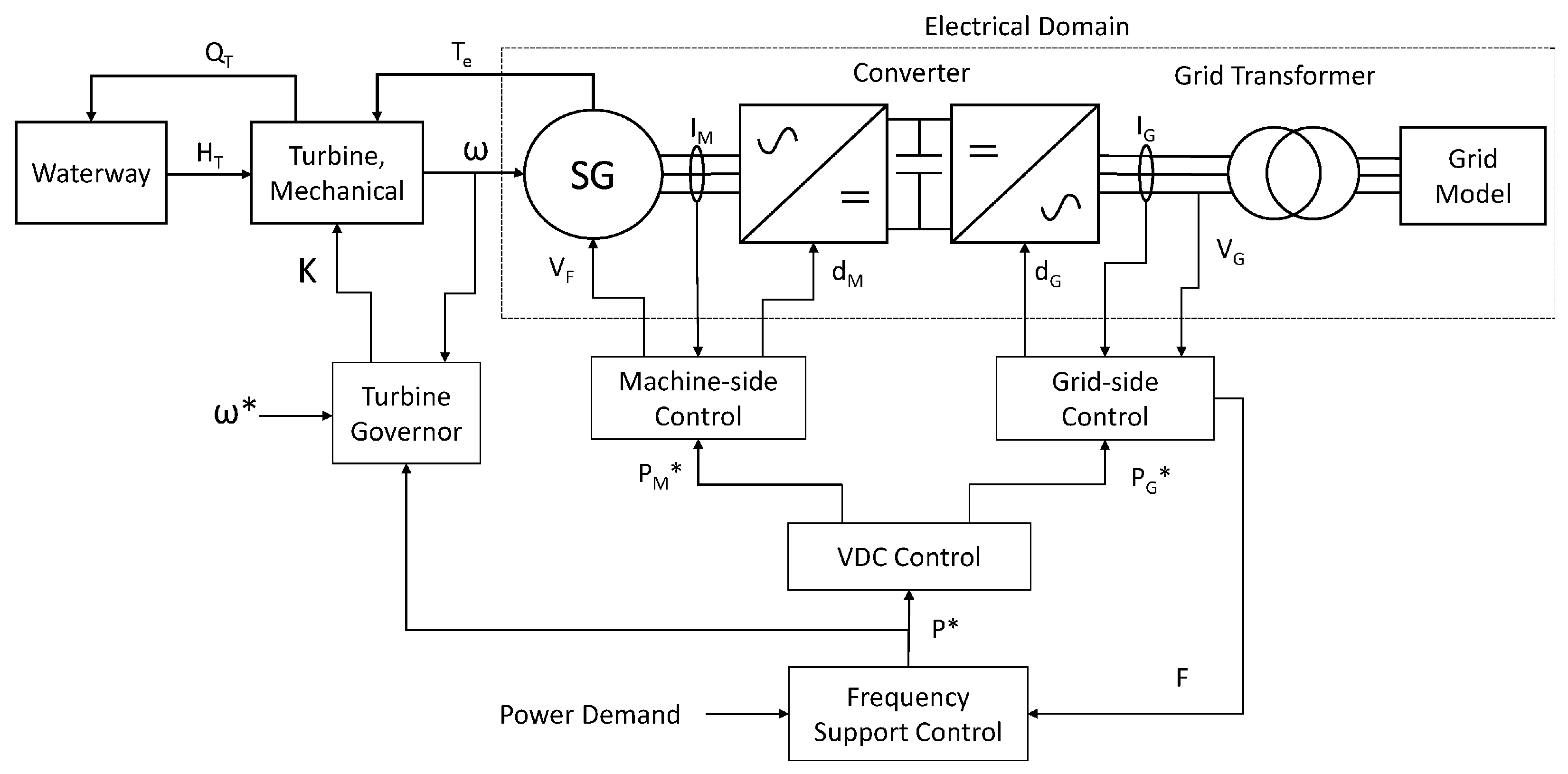
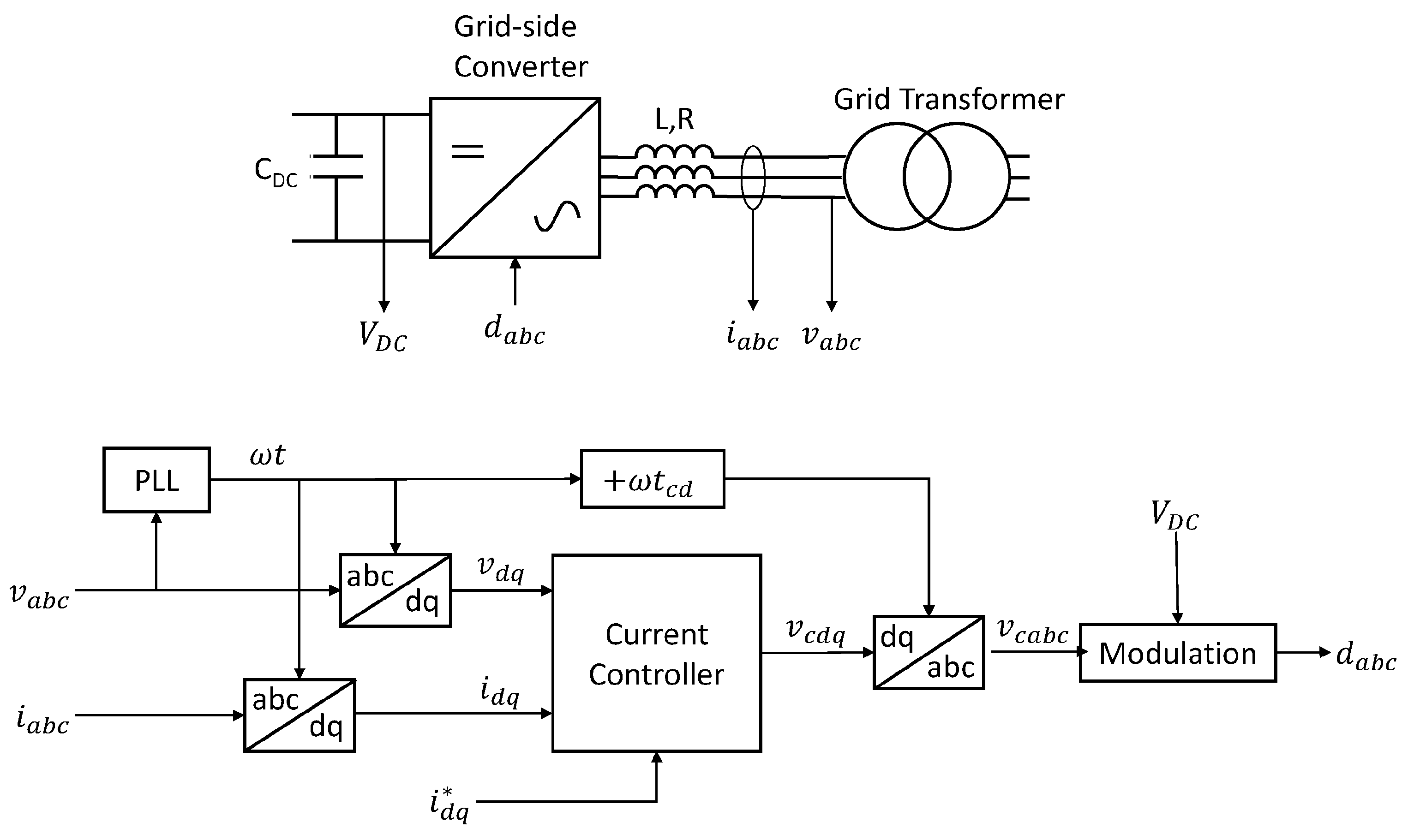
The complete structure of the model and control system is shown in
Figure 1. The system is modelled using MATLAB/Simulink R2023b (23.2), with the electrical domain modelled using the Simscape Electrical Specialised Power Systems block set.
The waterway model provides the pressure head at the turbine, , based on the turbine flow . The turbine model functions as a variable throttle on the hydraulic side, calculating the based on , the turbine speed, , and the guide vane opening K. The mechanical torque is also calculated, and this is used in the mechanical model along with the electrical torque from the generator, , to calculate .
For the controller, the turbine governor regulates the turbine speed through the guide vane opening, while the grid power is determined by the frequency support controller and regulated by the grid side controller. The machine-side controller is used to regulate the converter’s DC-link voltage. The power demand is also fed forward to the turbine governor to improve performance. This method allows the stored energy in the turbine inertia to be used to improve the system’s response speed. However, it is unsuitable for the pumping mode of operation, where the turbine speed determines the pumping power. For simplicity, only the generating mode of operation of the plant will be considered.
The waterway, turbine, and control systems operate in the per-unit (p.u.) system, with the electrical domain using real-world units. The various blocks in
Figure 1 will be described in more detail in the following sections.
2.1. Waterway, Turbine, and Mechanical System
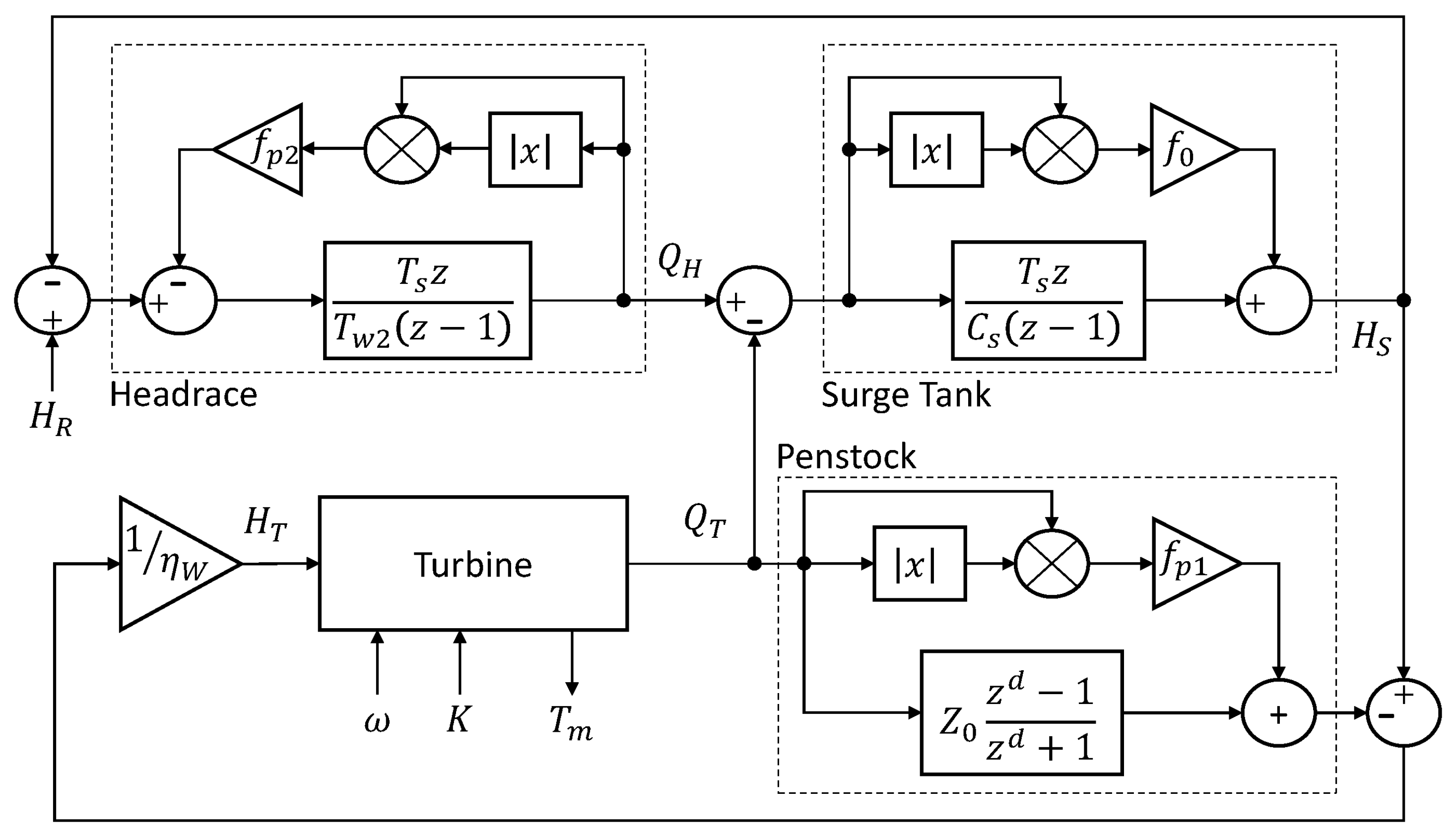
The model implements a typical high-head system, with a waterway consisting of a long headrace, surge chamber, and a short penstock connected to a single Francis turbine. The waterway headrace is modelled based on non-compressible flow, while a travelling-wave model is used for the penstock, and this arrangement is described in [
3]. The waterway model was discretised to improve the simulation speed, particularly with the comparatively short timesteps required for the converter model, with integrators implemented using the Backward Euler method to eliminate algebraic loops.
The discretised waterway model is shown in
Figure 2.
,
, and
are the pressure heads at the reservoir, surge tank and turbine, respectively.
and
are the flows in the headrace and turbine. The parameter
is the wave travelling time [
13] in the waterway which causes the delay
d. The delay parameter
d is calculated as in (
1), based on the sampling time step
, for which 1 ms is used.
The values of the parameters
,
,
,
,
, and
are given in
Table 2 and taken from [
13]. The parameter
is the waterway efficiency at the rated reservoir head and flow and is included so that the turbine head will be 1 when operating at rated conditions.
For the turbine, a Euler model is used [
30], providing a more straightforward implementation than the lookup table-based models used in many turbine-focused studies and greater accuracy at speeds below rated compared with the simple models used in system studies [
3].
The turbine throttling equation is given by (
2), while the mechanical torque
is given by (
3). These use the non-dimensional starting torque
, given by (
4), which depends on the guide vane angle
, given by (
5):
The turbine parameters
,
,
, and
are taken from the same source as the waterway [
13], and provided in
Table 2. They represent a typical high-head turbine. As this study is concerned with the generating mode of operation, the pumping mode is not implemented in the turbine model. Mechanically, the rotating system is modelled as a single lumped inertia representing the combined inertias of the generator and turbine, as shown in (
6).
is the generator electrical torque and
H is the inertia constant.
is the turbine efficiency at rated speed and power. The mechanical model is discretised at the same 1 ms timestep, with integration using the Forward Euler method.
2.2. Generator and Converter
Built-in models from the Specialised Power System block set of Matlab/Simulink were used to model the generator and converter. A fifth-order model was used for the generator, representing a salient-pole machine with damper windings. Parameters for a typical low-speed high-power hydroelectric generator were used [
31]. and are given in
Table 3.
For the converter, an averaged model was used, which represented the AC side as a controlled voltage source and the DC side as a current source based on the applied duty cycle. The averaged model resulted in a faster simulation time compared with a switched model and little reduction in accuracy for the dynamics of interest in this study [
32]. While the converter is likely to be based on an MMC, for simplicity, it was modelled as a 2-level voltage-source converter, as it was expected that the circulating current and voltage balancing controls needed for an MMC would have minimal impact on the dynamics. The 5 kHz sampling frequency used in the machine and grid-side controllers was based on the typical sampling frequencies used in an MMC. A converter with fewer levels would significantly reduce the sampling frequency, limiting the current control bandwidth. Converter parameters are given in
Table 4.
2.3. Turbine Governor
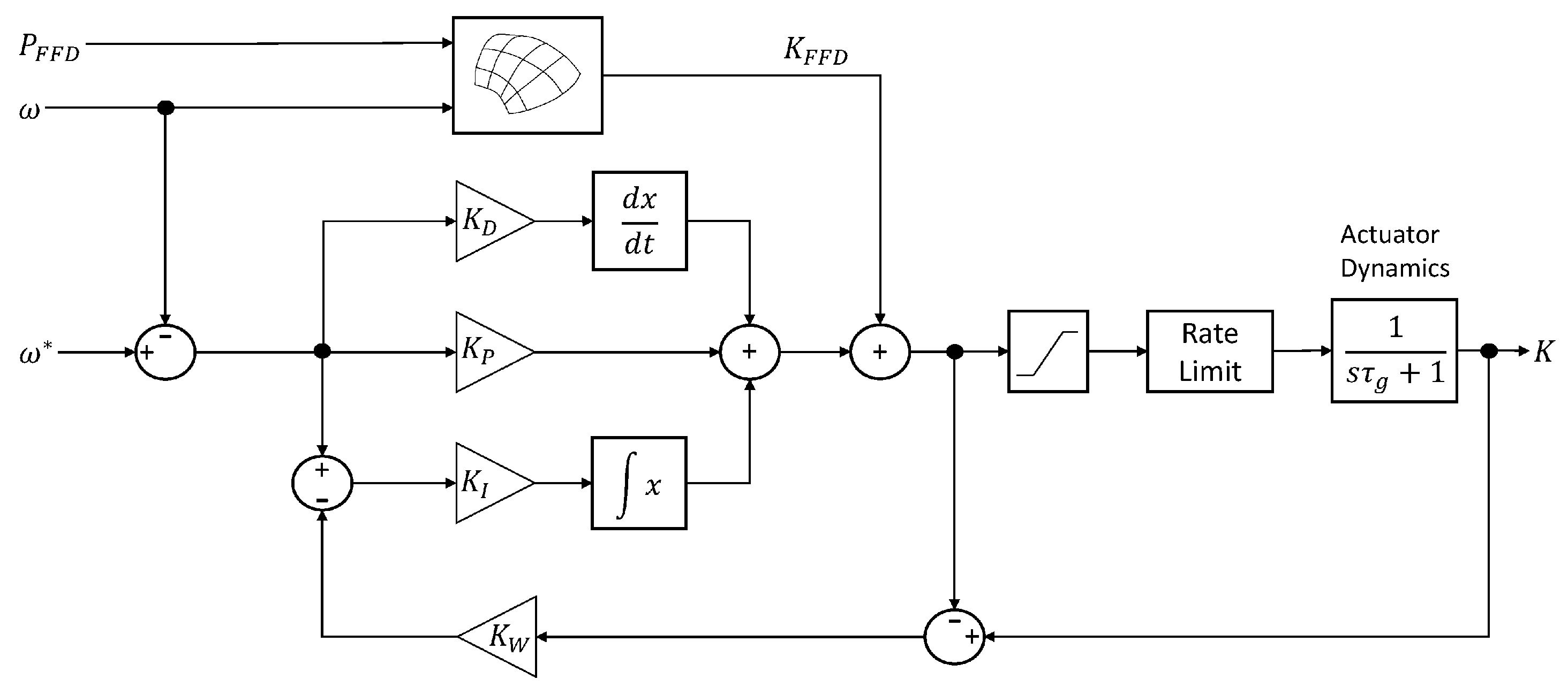
The purpose of the turbine governor is to regulate the turbine speed. To track the reference turbine speeds, the turbine governor configurations used in this research (PID and MPC) control the turbine guide vane position K.
2.3.1. PID Controller
The governor structure is shown in
Figure 3 and is based around a PID controller. Feed-forward is used to improve dynamic performance, with a lookup table used to calculate the guide vane feed-forward
from the turbine speed
and the power feed-forward value
. The guide vane position is subjected to saturation, and a rate limit is used to prevent pressure pulsations in the waterway, as is common practice in hydroelectric installations. As demonstrated in
Figure 3, guide vane actuation dynamics are based on a first-order response with a time constant
. As the rate limit, in particular, has a significant effect on the system’s response speed, the integrator features anti-windup using back-propagation, using the gain
. The values of the controller parameters are listed in
Table 5.
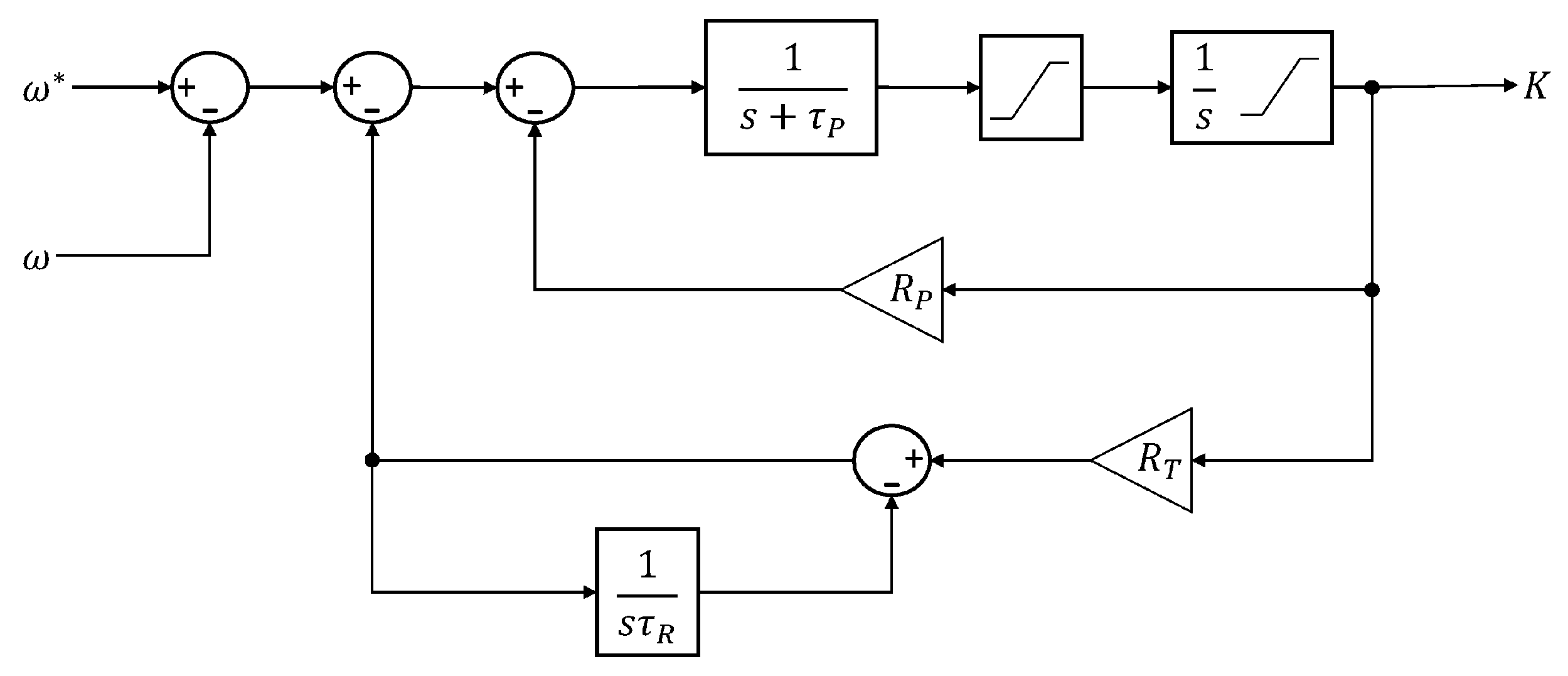
Additionally, a fixed-speed governor (shown in
Figure 4) was implemented so the performance of the variable-speed system could be compared with a conventional fixed-speed. The fixed-speed governor is based on a conventional two-stage hydraulic position servo, with permanent and transient droops [
3].
Parameters for the fixed-speed governor were taken from the same source as the turbine and waterway models [
13], and are listed in
Table 6.
2.3.2. Model Predictive Controller
MPC has been the most popular advanced control method recently, owing to its fast and effective optimisation-based solutions being more available due to the well-established computing power standards of today. MPCs are also robust and are good at handling non-linear systems such as hydropower plants [
20,
21,
22,
23,
24]. They were also validated for VSHP systems in a few studies [
14,
15,
16].
For the purposes of this research, a local output (turbine speed
) feedback linear MPC on the turbine governor side has been designed to achieve the optimal turbine speed
.
Figure 5 demonstrates the MPC turbine governor control diagram. The demanded electrical power
is used as the measured disturbance signal. The control signal is denoted by
K (guide vane opening).
The MPC optimisation problem [
33] is based on the minimisation of the quadratic cost function
subject to constraints on the states
and the control input
:
for the discrete-time linearised state-space system represented by:
For the cost function (
7), the prediction and control horizons are defined by
and
, respectively. The weightings are given by
,
, and
. The term
is a slack variable (non-negative) for the worst-case constraints. For the state-space model (
8), the variable
represents the measured disturbance. Assuming
, the mechanical system in (
6) becomes:
and the electrical system is defined as:
Recall the set of Equations (
2)–(
5) for the turbine and waterway models, and assume the ratio
. Substituting (
2), (
4) and (
5) in (
3), the mechanical torque is redefined as:
Substituting (
10) and (
11) in the derivative of (
9), the turbine speed dynamics become:
Augmenting the speed dynamics
with the rest of the turbine and waterway equations (parameters
) [
29], it is possible to represent the complete non-linear Variable-Speed Hydropower system by the generalisation below:
In the non-linear representation (
13), the state vector is chosen as
, the control action is given by
and the measured disturbance
. The output
uses the parameter vector set to
. The non-linear model is linearised around the operating points
and
. Taking the Jacobian linearisations around
and
, the state matrices are calculated:
Using
and
, the state-space model below can be defined:
Note that v was not involved in the linearisation process because it is a measured output disturbance and cannot be manipulated.
For the MPC turbine governor, the sampling time
= 0.1 s was chosen. Then, omitting the delta terms for the purpose of clarity and using the forward Euler approach for discretisation, the final state-space model of the system becomes:
The MPC uses a Kalman filter for estimations:
where
represents the estimated states and
denotes the estimated system output. The term
L is the Kalman gain.
The control horizon is chosen as and the prediction horizon is selected as . The control limits are set to and , as constraints. The weights are and .
2.4. Machine-Side Controller
Field-oriented control is used in the generator-side controller to directly regulate the generator torque by controlling the stator current flowing in the rotating reference frame and the field current.
In the per-unit system, the generator electrical torque is given by (
18), where
is the stator flux linkage in the rotating reference frame, with the
d axis aligned with the field, and
the stator current. Given knowledge of
, the current demand
can be calculated to achieve the desired torque:
For simplicity, the controller uses the generator air gap flux calculated in the model. This approach is analogous to using flux sensors within the generator. Sensorless observer systems can be used to estimate the flux [
34], but these are complicated to implement as the current in the damper windings is unknown. The terms
and
may be expanded as:
The stator voltage equations are then given by:
where
and
stand for the stator winding resistance and rotor angular frequency, respectively.
The current references are calculated using (
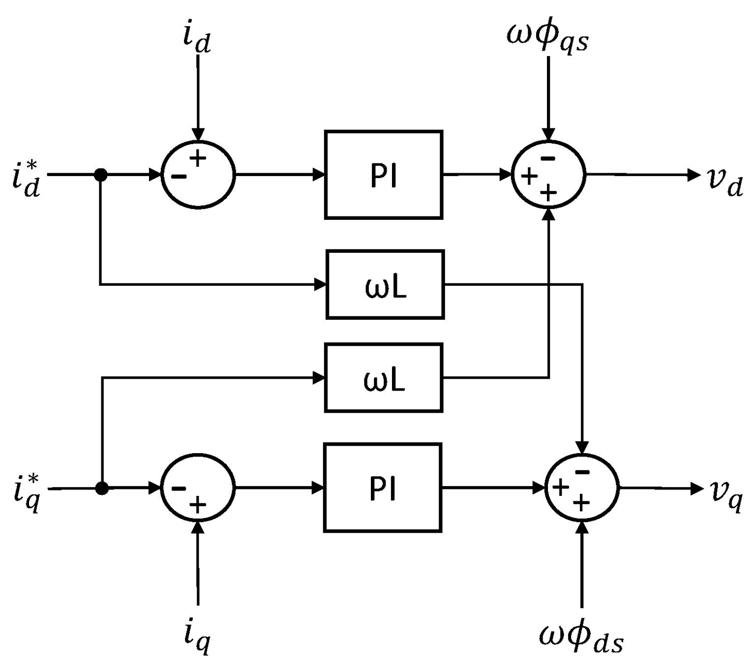
18), a standard vector current controller based around a Proportional-Integral (PI) controller (shown in
Figure 6) with cross-coupling compensation and feed-forward of the generator EMF (calculated from the measured flux).
Using a sampling frequency of 5 kHz, the stator current controller gains were tuned following the Internal Model Control (IMC) method [
35] principles, with
and
providing a reasonable first-order response with no overshoots. The mathematical model of this controller and the calculation of its gains are given by:
where
denotes the desired frequency response bandwidth,
stands for the maximum bandwidth without overshoots, and,
is the controller time delay.
The generator field current is controlled to maintain a constant 1 p.u. flux in the d-axis. The required field current, referred to the stator,
, is given by (
22), where
is the d-axis flux demand,
the stator leakage inductance,
the magnetising inductance, and
the stator current in the d-axis. The field current is regulated using a PI controller as well:
The field current controller proportional and integral gains are and , respectively. The tuning parameters were selected manually to obtain a slower response than the stator’s current controller. The same sampling frequency value of the stator controller was used.
Recall that the generator used is a fifth-order salient-pole one. For further reading of generator reactance calculations, the reader may refer to [
29]. The generator torque demand, which determines the current demand, is limited to 2 p.u., allowing full power output down to 0.5 p.u. generator speed, which was selected for flexibility during the controller development. Further refinement of the current limit, allowing for a reduced converter current rating, would need to take into account the operating speed range of the turbine as well as the control of the generator excitation.
2.5. Grid-Side Controller
Two methods are implemented to control the power on the grid side of the converter: a conventional Vector Current Controller (VCC) and a Virtual Synchronous Machine (VSM).
The primary purpose of a VSHP is the flexibility it can provide to the grid among the inflexible converter-connected solutions like solar and wind power. However, a VSHP needs a converter in front of the generator because of its structure. This positioning may reduce the inertia on the grid side, although less so than inflexible power solutions. Therefore, synthetic inertia was introduced to balance it out by researchers [
36] in a case study on wind turbines. However, some mechanical problems were observed due to the incompatibility of the synthetic inertia controller with the turbine controller. A VSHP may be more practical, since its synchronous generator can quickly provide synthetic inertia service using its real inertia.
A modified version of a conventional VCC can provide the synthetic inertia needed, but it is dependent on the differentiation of the grid frequency measurement and a Phase-Lock Loop (PLL) mechanism and, thus, may suffer from noise that may cause issues in fragile grids. A VSM can mitigate the disadvantage of weak grids by handling converters with low virtual inertia while keeping high virtual inertia for the synthetic inertia support. As a result, the grid-side converter controller of this research combines the VSM and VCC for efficient synthetic inertia gain.
Note that the constraints on converter current and voltage are crucial for the system’s safety and reliability [
9]. The current controller discussed in
Section 2.5.1 and the anti-current controller outlined in
Section 2.5.3 offer valuable insights into the current constraints employed in this research. While the converter voltage constraints are not explicitly implemented, they are subject to the limits of the DC-link voltage.
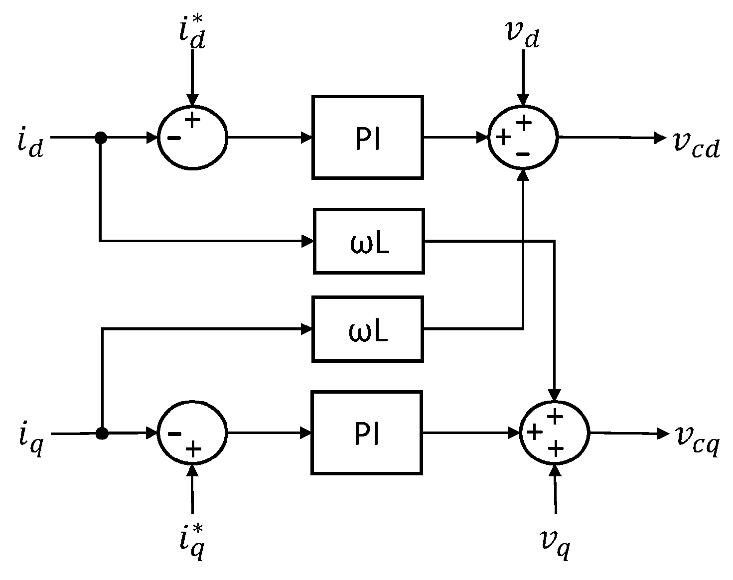
2.5.1. Vector Current Controller
The VCC and its current controller are demonstrated in
Figure 7 and in
Figure 8, respectively.
The PLL (
Figure 7) synchronises to the grid voltage
. The
and the grid current
go through the d-q transformations for the current controller. The current controller produces the converter voltage denoted by
. It is tuned using the IMC method [
35] for 100 Hz bandwidth.
Due to limits to the converter current capability, the d-axis current reference is limited to 1 p.u., while the magnitude of the current reference is limited to 1.2 p.u. The voltage demand is not limited, except by the limits of the DC-link voltage. In this study based around a simplified converter model, the converter typically operates at a modulation index of around , providing significant voltage headroom. A more realistic implementation would operate at a higher modulation index in order to maximise converter utilisation, but this would require a more detailed converter model to fully analyse the potential interactions.
2.5.2. Virtual Synchronous Machine
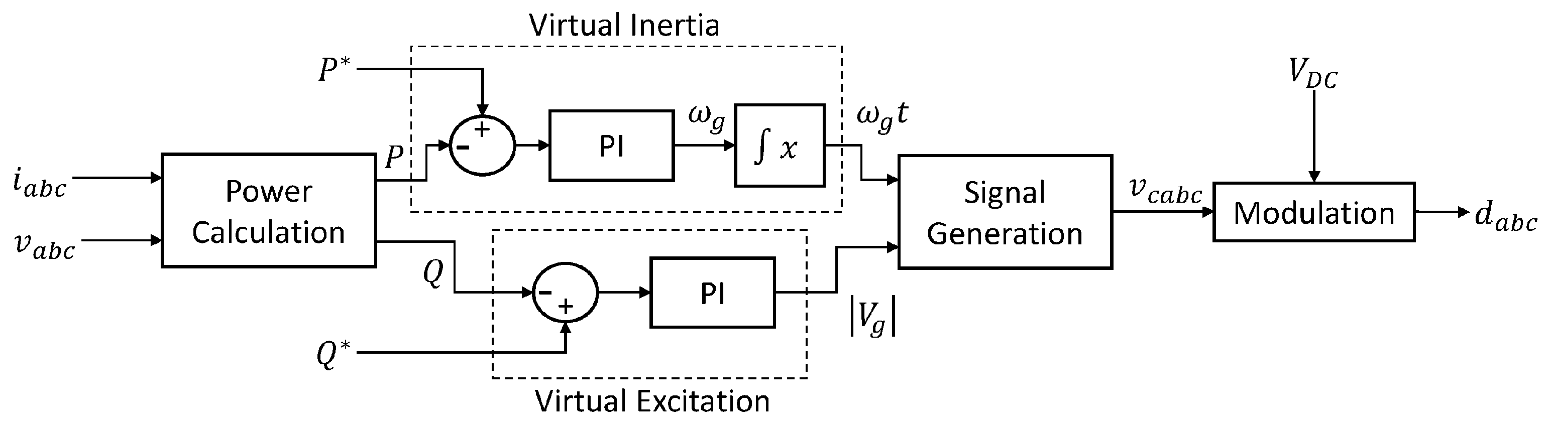
The structure of the VSM is shown in
Figure 9. From the measured grid voltage and current,
and
, the instantaneous real and reactive powers
P and
Q are calculated using (
23) and (
24). PI controllers are then used to set the reference angular velocity
and magnitude
of the reference voltage, with
being further integrated to obtain the reference angle
. These are used to generate the reference phase voltages
, from which the duty cycles
for the three phases are obtained:
The dynamic performance of the synchronous machine is calculated by:
where the term
stands for the p.u. mechanical power input, and
denotes the p.u. electrical power output. The reference angle
is obtained by:
where
is the load angle between the grid voltage vector and the electromotive force (EMF) of the generator.
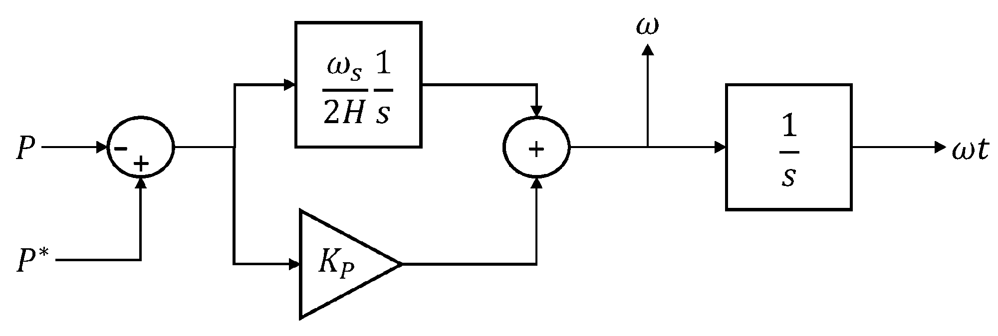
An issue with modelling a synchronous machine is the emulating the effects of the damper windings; for instance, some methods produce a permanent frequency droop characteristic [
37], and while this may be desired, it is better to be decoupled from the VSM operation. Therefore, in this research, a PI controller (shown in
Figure 10) has replaced (
26).
Here, the integral gain determines the virtual inertia according to:
where
is the synchronous speed of the grid, and
H is the virtual inertia constant. The proportional gain,
, can be tuned to achieve the required level of damping in the response, and a higher level of damping is used than would be found in a real synchronous machine.
2.5.3. VCC and VSM Combined
The VCC and VSM combined control structure is depicted in
Figure 11. This is inspired by the controller in [
38] used for power synchronisation. Note that the figure contains two grid frequencies, the
and the
, which stand for the PLL and VSM frequencies, respectively.
The resonance damping block shown on the combined controller is expanded as in
Figure 12. It is a first-order high-pass filter used to damp resonances that may be present in VSM systems.
The anti-current controller block is shown in
Figure 13 in detail. Its purpose is to supply current demand values to the existing current controller, such that the voltage demand
equals the reference from the VSM,
, in this way the current-limiting functionality of the current controller is maintained.
The current controller (
Figure 8) contains cross-coupling terms for which the integral component of the PI compensates. Therefore, the integral action may be seen as optional and removed under certain circumstances because the resulting steady-state error will be minimal. In the case of the combined controller, while the VSM is operating, the integral action is disabled. The current controller output
depends on
,
, and
; the anti-current controller generates a current reference
so that the output of the current controller
is equal to
. Note that, since the
passes through a hard limit, the current limitation will still be enabled. The entire set of grid-side control parameters is given in
Table 7.
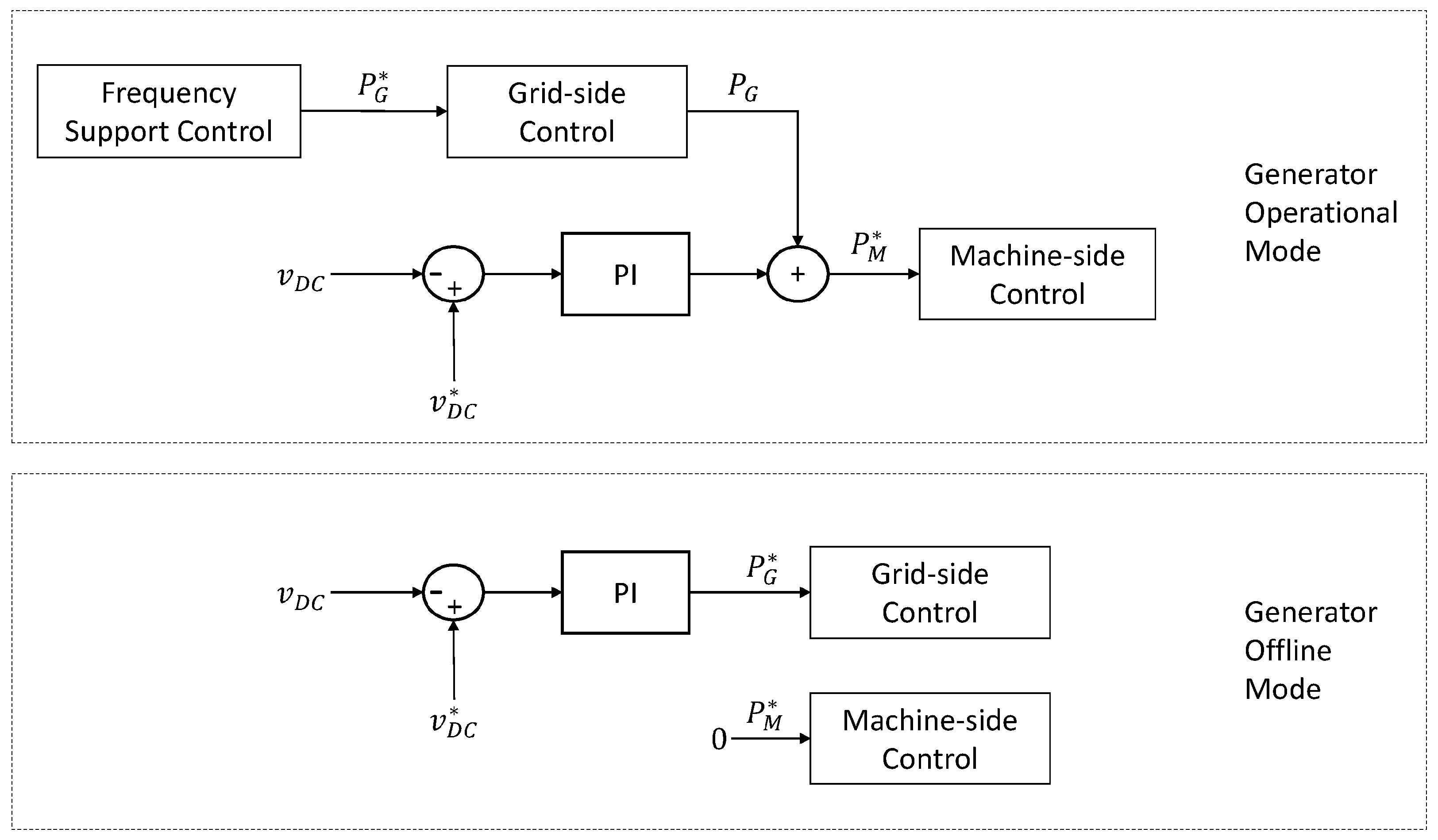
2.6. DC-Link Voltage Controller
The DC-link voltage control scheme is illustrated in
Figure 14. In the operational mode, the frequency support controller sets the real power demand for the grid-side converter,
.
The real power demand for the machine-side converter, , is used to regulate the DC-link voltage of the converter using a PI controller, and to improve the response, the measured grid power is used in a feed-forward fashion. The proportional gain was set to and the integral gain to . These presets were sufficient for the PI controller, but under different scenarios, further adjustments, especially on the integral action, might be necessary.
2.7. Frequency Support Controller
This research takes the UK Grid Code Issue 5 [
39] as a reference for the grid tests in its simulations. The grid code declares the items below for frequency support services:
Primary: The response reaches the desired value within 10 s when the grid frequency experiences a drop, and it must sustain at no lesser reduction after that.
Secondary: The response reaches the desired value within 30 s when the grid frequency experiences a drop and must sustain for at least 30 min.
Note that, as of 2024, UK Grid Code Issue 6 is in place, which can be accessed from [
40] along with its update packages and previous grid codes. The primary and secondary frequency responses are governed by frequency droop control. The droop control offers extra power proportional to the drop and is limited within −0.5 Hz below the nominal value. Meanwhile, the generator must offer at least
of the rated power. Furthermore, a deadband with the range ±0.015 Hz within the neighbourhood of the nominal value is allowed. The generator can receive payment for such optional frequency support services. Should the frequency exceed the nominal value, reducing the power output is mandatory. This can become an additional payment source for the generator. Another frequency support service is the fast start. In this case, the generator must rapidly start from a standby condition, which is one of the strengths of Variable-Speed Hydropower Technology.
2.7.1. Operating Limits
Ref. [
9] defines the limits on the operating region of the turbine during the generation by:
Minimum and maximum values for the rotor speed to disallow the cavitation and blade damage the high angle of attack may cause.
Introducing a minimum power limit for the given speed, as considering the turbine is running at a high speed on low power and discharge speed, it is highly likely that there will be excessive swirl in the discharge tube. The minimum power limit can stop the forming of cavitation and vortex rope. This measure can allow operational stability for the plant. Maximum power limits are introduced in the case of vice versa.
Imposing limits on the generator and converter currents.
The first set of limits appears to be the most crucial for the controller because the generator providing energy for a rapid frequency response will slow down the rotor, which may cause blade damage if the rotor speed ends up decreasing dramatically.
2.7.2. FSC Control Structure
This subsection presents the FSC layout divided into three pieces: the power change calculation, power limit implementation, and power reference calculation.
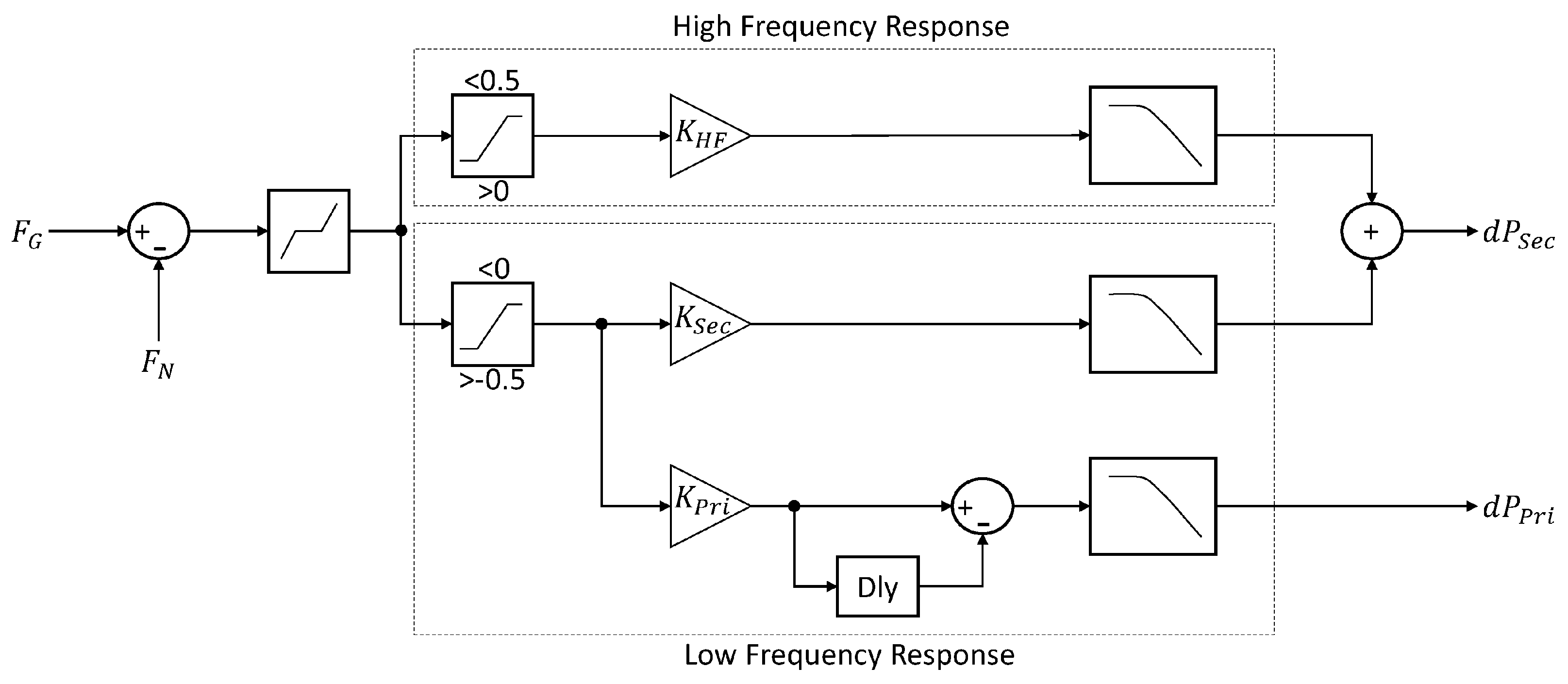
Figure 15 demonstrates the calculation of power change (primary and secondary), performed by taking the difference of
, denoting the grid frequency, and
the nominal frequency.
After that, the headbands are implemented. Droop represented by
calculates the primary response, which is limited by the 20 s delay block and a low-pass filter. The secondary and high-frequency responses are kept separate and also go through low-pass filters. The structure shown in
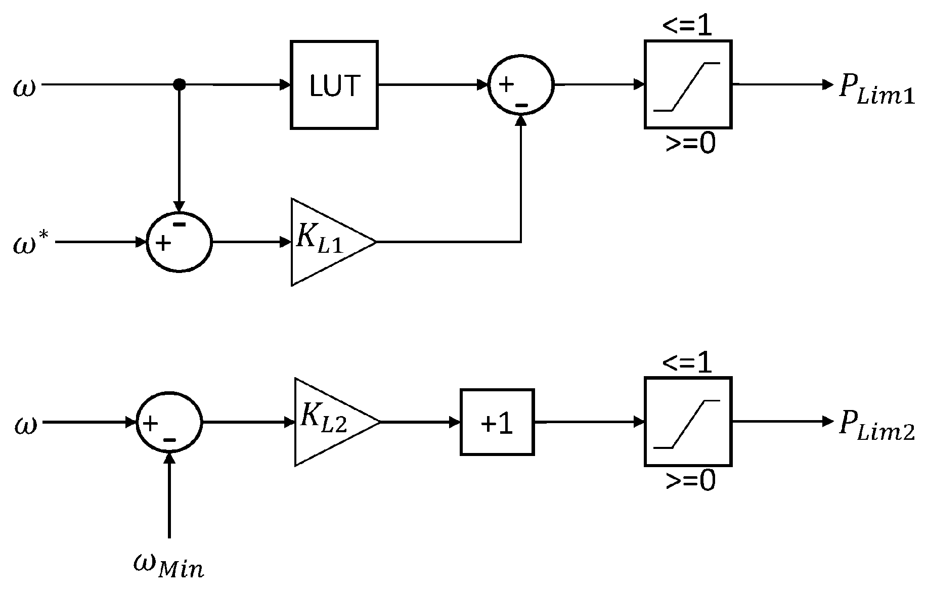
Figure 16 calculates the power limits. Of these,
works against the turbine stall, which may occur if the demand exceeds the maximum power available for the current speed. The speed is regulated back to the reference value
with the help of a look-up table set for the actual speed
and the droop gain,
, which can lower the power demand and re-accelerate the rotor.
On the other hand, is a preventive measure to halt the speed from falling behind the minimum value allowed and enables a linear reduction of the power using the droop gain denoted as the .
As the last piece of the FSC,
Figure 17 shows the calculation of the grid converter’s power reference
and the turbine governor’s feed-forward term
.
The FSC control parameters are provided in
Table 8.
2.8. Representative Grid Model
This study uses two different grid models: a stiff grid and a modified version of the representative grid model from [
41]. The stiff grid model involves a voltage source, resistance, and inductance. The latter is illustrated in
Figure 18 and is referred to as the representative grid model.
The difference to [
41] lies within station 3, which is, in contrast, connected to an inverter and represents a voltage-generating HVDC link (wind farm). Parameters used in the test scenarios are given in
Table 9.
Note that the parameters were chosen based on the idea of having a significant amount of hydropower available. What this means for the grid is a considerable stack of inertia. The hydropower stations in the model have a slow frequency response; thus, the thermal stations were also kept slow to increase the difficulty of frequency response for the VSHP, challenging the model to highlight its potential presence. The representative grid model was designed like this to assess the performance of VSHP and give a more realistic representation of the Nordic grid power mix.
3. Results
One of the major contributions of this research lies within the comprehensiveness of the control approach and the broadness of the plant model. The overall controller is an augmentation of multiple controllers responding to lower-level plant management solutions and higher-level plant management solutions. To expand the statement, the turbine governor, for example, deals with the turbine speed, which can be categorised as part of the lower-level plant management, while the control strategies for fault-ride through, frequency dip mitigation, and synthetic inertia provision could be placed in the higher-level plant management category. For these reasons, this section presents the simulations in the following order: PID and MPC turbine governors, generator torque control, VSM and VCC operation, fault-ride-through test, and frequency support control tests for the grid.
The anti-windup PID governor from
Figure 3 of
Section 2.3.1 using the parameters given in
Table 5 is analysed for the first set of results. The response of the governor to a step change of 0.1 p.u. on the power is shown in
Figure 19. The reference turbine speed
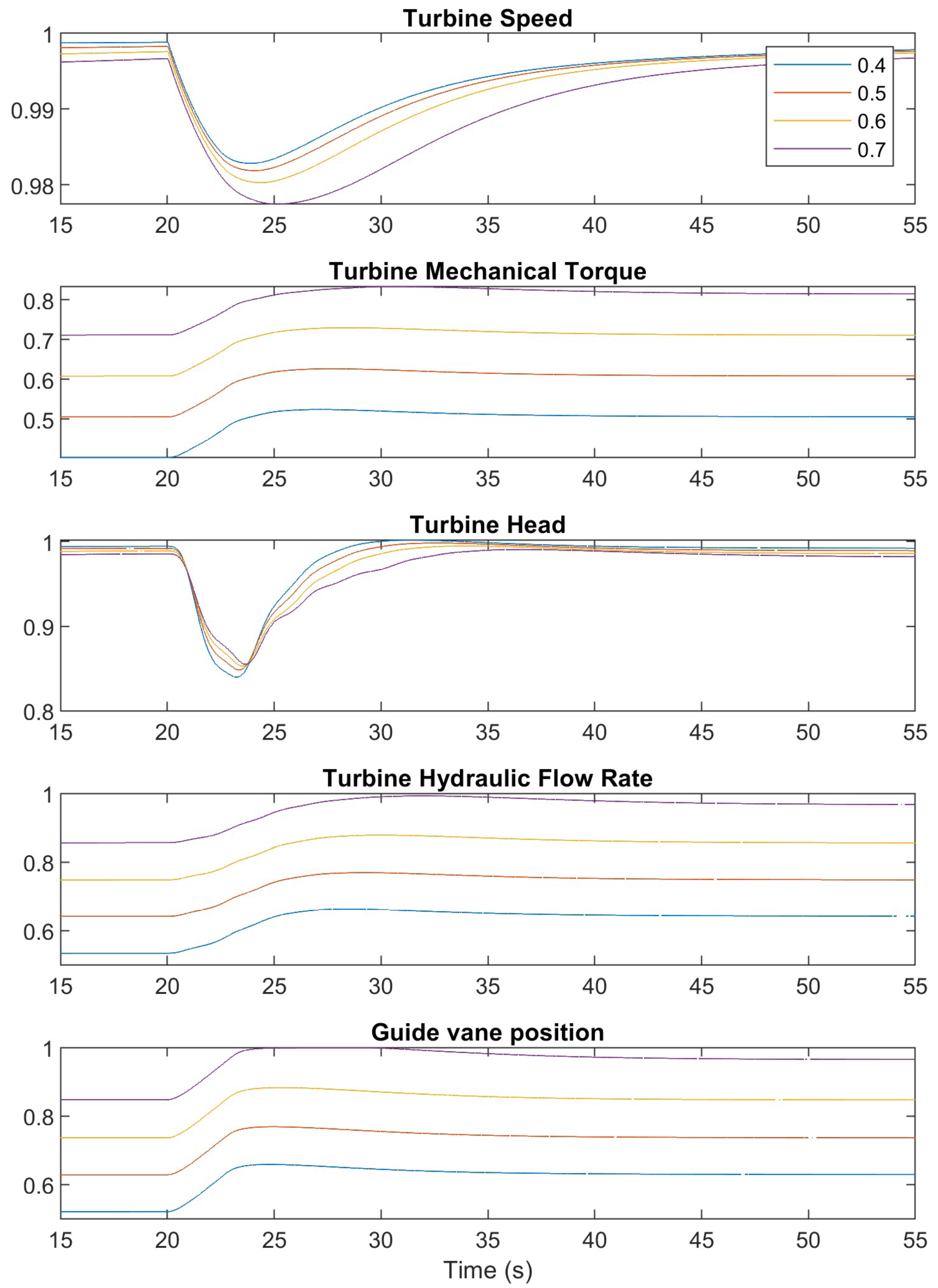
= 1 p.u. is tracked for various initial power values from 0.4 p.u. to 0.7 p.u. Following the step change, a decrease is observed in turbine speed. As is seen in the bottom subfigure, the governor responds to the decrease by opening the guide vane, which increases the turbine hydraulic flow rate and the turbine mechanical torque. With enough torque provided, the turbine speed starts to recover and the guide vane position begins to settle to its final value. This is also visible in the turbine head subfigure, which reflects the changes in the turbine speed.
Figure 20 shows the response of the MPC governor to the same step change applied to the PID governor previously for the initial power output of 0.7 p.u. The 0.1 p.u. step change is applied at
t = 40 s in this test for demonstrative purposes. Note that the Y-axes use the p.u. system which is the case for all figures in this section unless stated otherwise. The MPC response is observed to have fast transient characteristics. The limits on the control action are visibly functioning. The heads and flows of the hydropower system are observed to react a bit more aggressively this time, which might prove to be a slight issue in practical terms. The hydraulics’ reaction can be smoothened with tuning, but this will come at a cost for the tracking performance (see
Table 10). However, future studies will consider different modelling options for the MPC, and smoother transitions can be achieved without much compromise on the tracking performance.
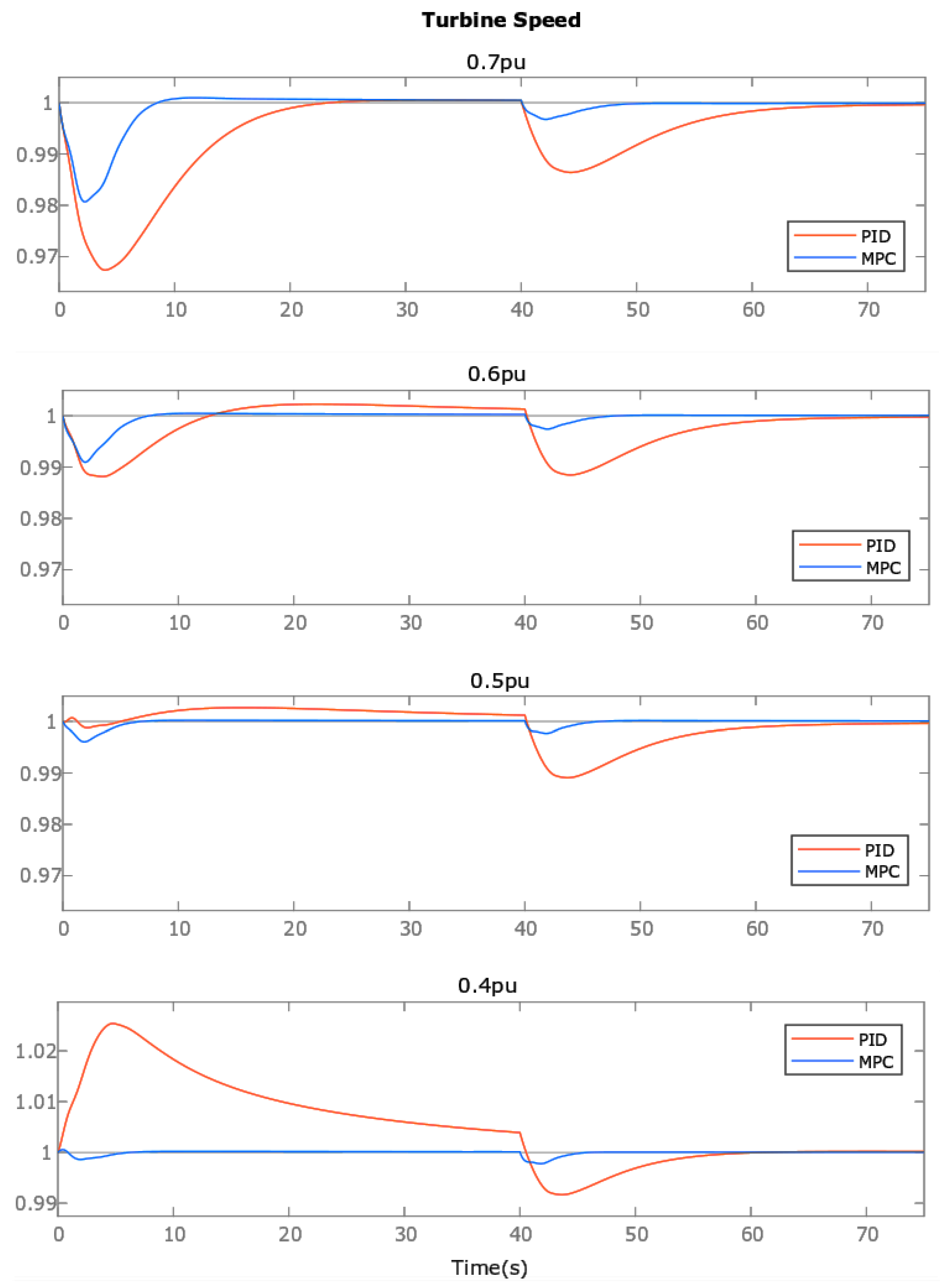
After introducing the MPC turbine governor, a comparison with the PID turbine governor can be made.
Figure 21 and
Figure 22 compare the performance of the governors from the start-up at
t = 0 s to a step change of 0.1 p.u. applied at
t = 40 s for the power output value varying between 0.4 p.u. and 0.7 p.u. The MPC-1 that refers to
Figure 21 has been tuned aggressively with priorities set on tracking performance and speed, while the MPC-2 that refers to
Figure 22 has been tuned moderately. The PID governor used in both cases is the same one.
The results show that the MPC has a much faster transient response overall, with smaller rise and settling times. It also shows smaller overshoots that amount to zero or insignificantly low percentages, thus proving superior tracking performance.
To verify the graphical results,
Table 10 presents the Root-Mean-Squared Errors (RMSE) for the given set of power outputs and compares the PID and the MPC governors.
According to the
Table 10, at the power output 0.7 p.u. for which the PID governor was originally tuned, the MPC-1 outperforms it by
and the MPC-2 outperforms it by
, whereas the tracking of MPC-1 is superior to MPC-2 by
. At the power output 0.4 p.u., MPC-1 and MPC-1 show
and
improvement compared to the PID, respectively. In this case, MPC-1 is superior to MPC-2 by
.
Due to its Kalman filter, the MPC adapts to variations in the power outputs and, therefore, does not produce the same amount of overshoot as the PID. The capability of adapting to different operating conditions is an important motivation to consider advanced control solutions like the MPC instead of the dominantly used conventional PID turbine governor approaches, which need to be re-tuned each time. The adaptability of the MPC would be a huge plus for the Variable-Speed Hydropower technology, which will demand rapid shifts in operating conditions.
Figure 23 presents the torque and current tracking performance of the machine-side controller from
Section 2.4. Both variables reach the desired values very quickly and do not exhibit any significant overshoots.
The VSM controller is compared to a Synchronous Machine (SM) in
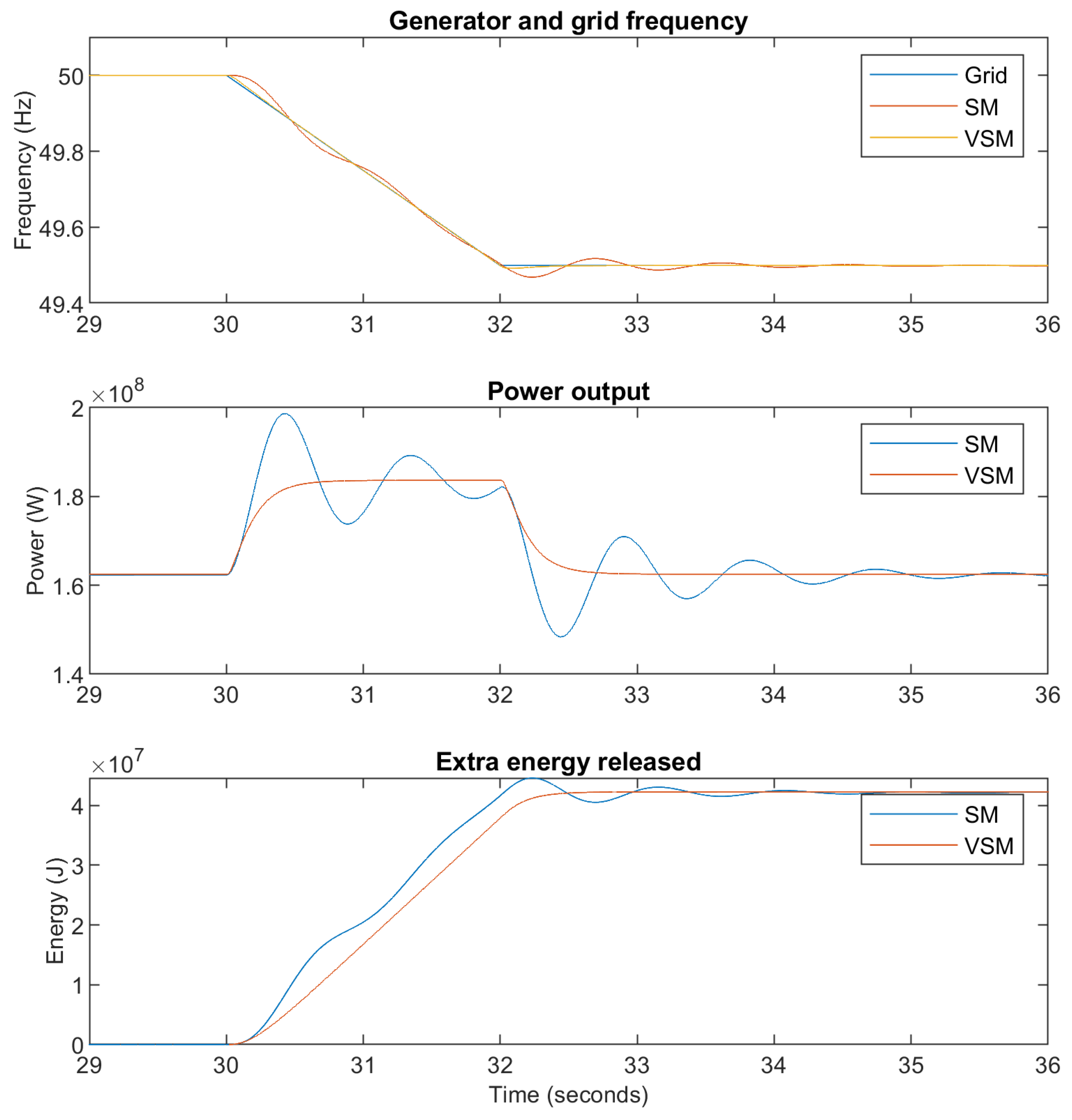
Figure 24. The grid frequency is taken down in a ramp from 50 Hz to 49.5 Hz within 2 s. It is seen that the power used and energy released by the VSM is similar to that of the SM but without oscillations. The damping of the VSM causes a slower energy release, but the difference is minimal. It is shown the VSM can provide smoother power and energy transitions to support the grid.
The VCC-VSM combined control that was introduced in
Section 2.5.3 alternates between a VCC and a VSM.
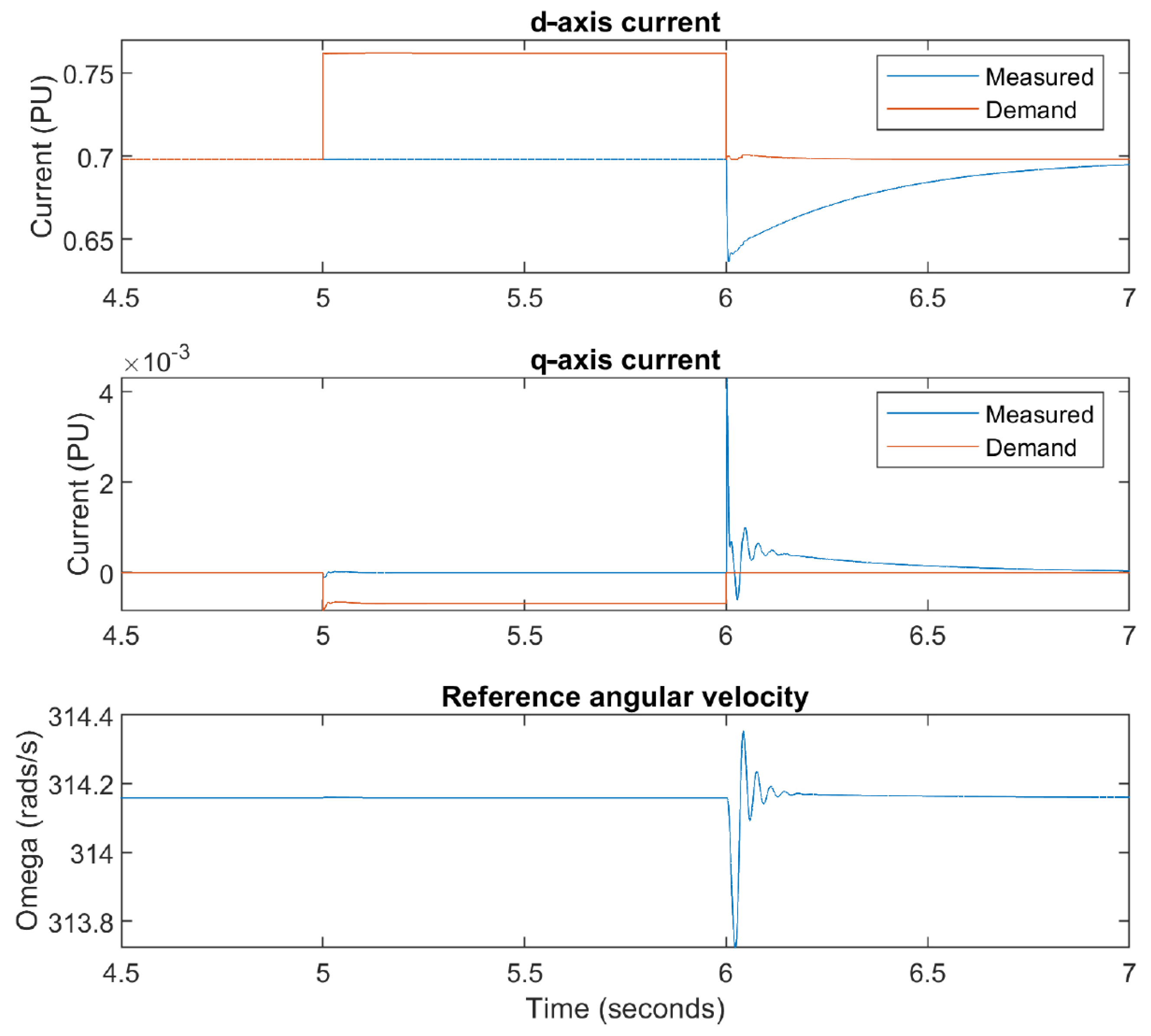
Figure 25 shows the d-q current values and reference speed
during the deactivation of the VSM between
t = 5 s and
s. In this period, the d-axis current demand rises, whereas the q-axis current demand falls because the VSM takes the initial value of the integrators of the current controller. However, the impact on the measured current is trivial. At
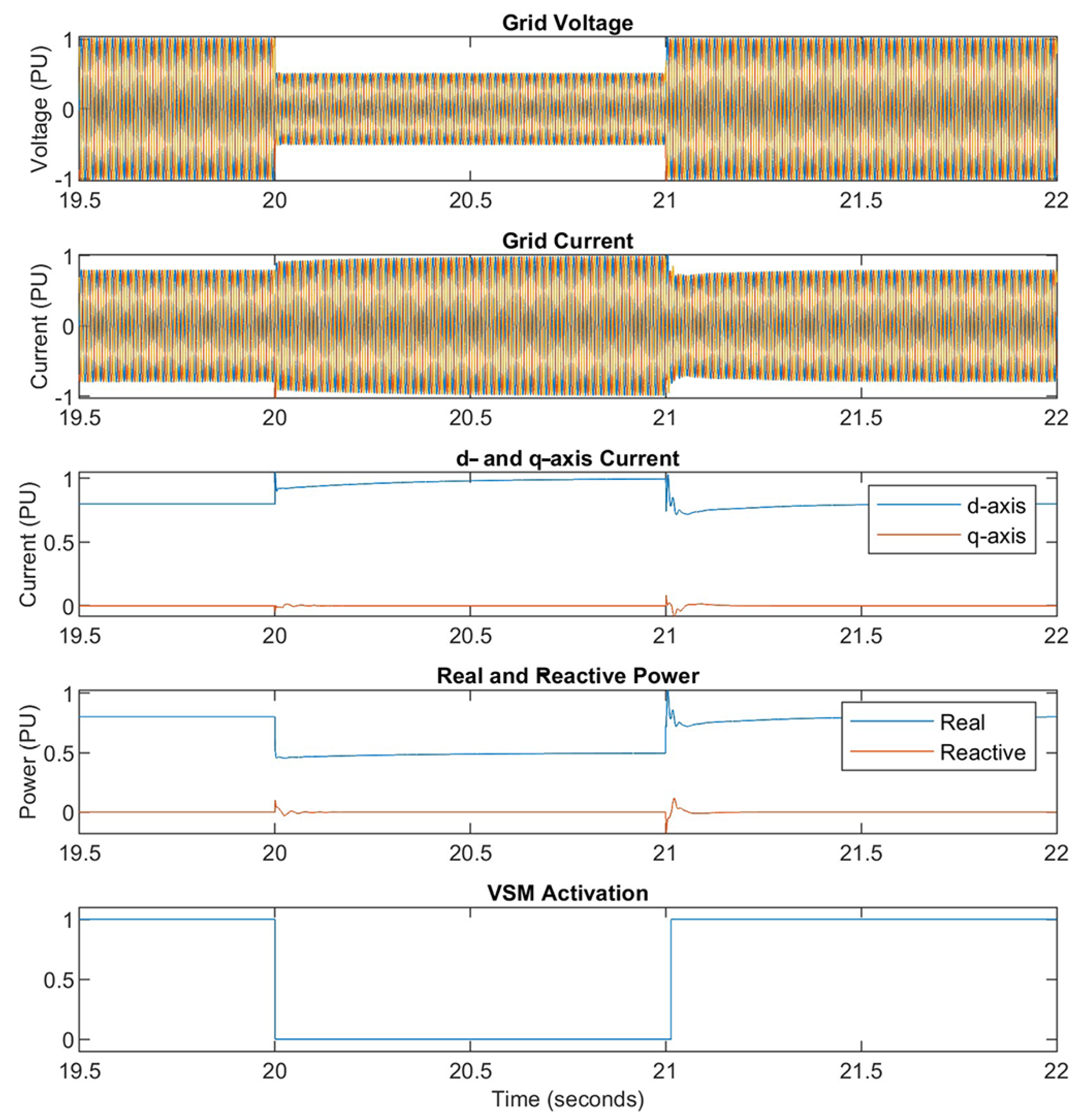
s, the VSM reactivates, and the current controller integrators are zeroed out, which causes the transients in the figure. While the DSM is deactivated, the combined controller transitions to the VCC, which is most likely to happen during a grid fault. Since such an event is bound to contain more significant transients, the transients observed during the switching are anticipated to be negligible.
The grid fault ride-through test in
Figure 26 verifies this. For this test, the grid voltage is subjected to a dip that amounts to the
of its nominal value which lasts for 1 s. This was chosen deliberately to create a strong response and clearly demonstrate the reaction of the electrical and mechanical systems. The reflection of the voltage dip in the mechanical part of the system is shown in
Figure 27. The VSM deactivates once the voltage gets below
of the nominal value, and similar d-q responses to those in
Figure 25 can be seen. The rising currents lead to maximum real power transfer, and the grid voltage gets restored to the nominal value. When this happens, the VSM is re-activated. During the dipping event, the generator begins to speed up due to the power transfer, and the governor starts cutting the guide vane to compensate for it and re-opens once the generator speed is back to the set-point (see
Figure 27).
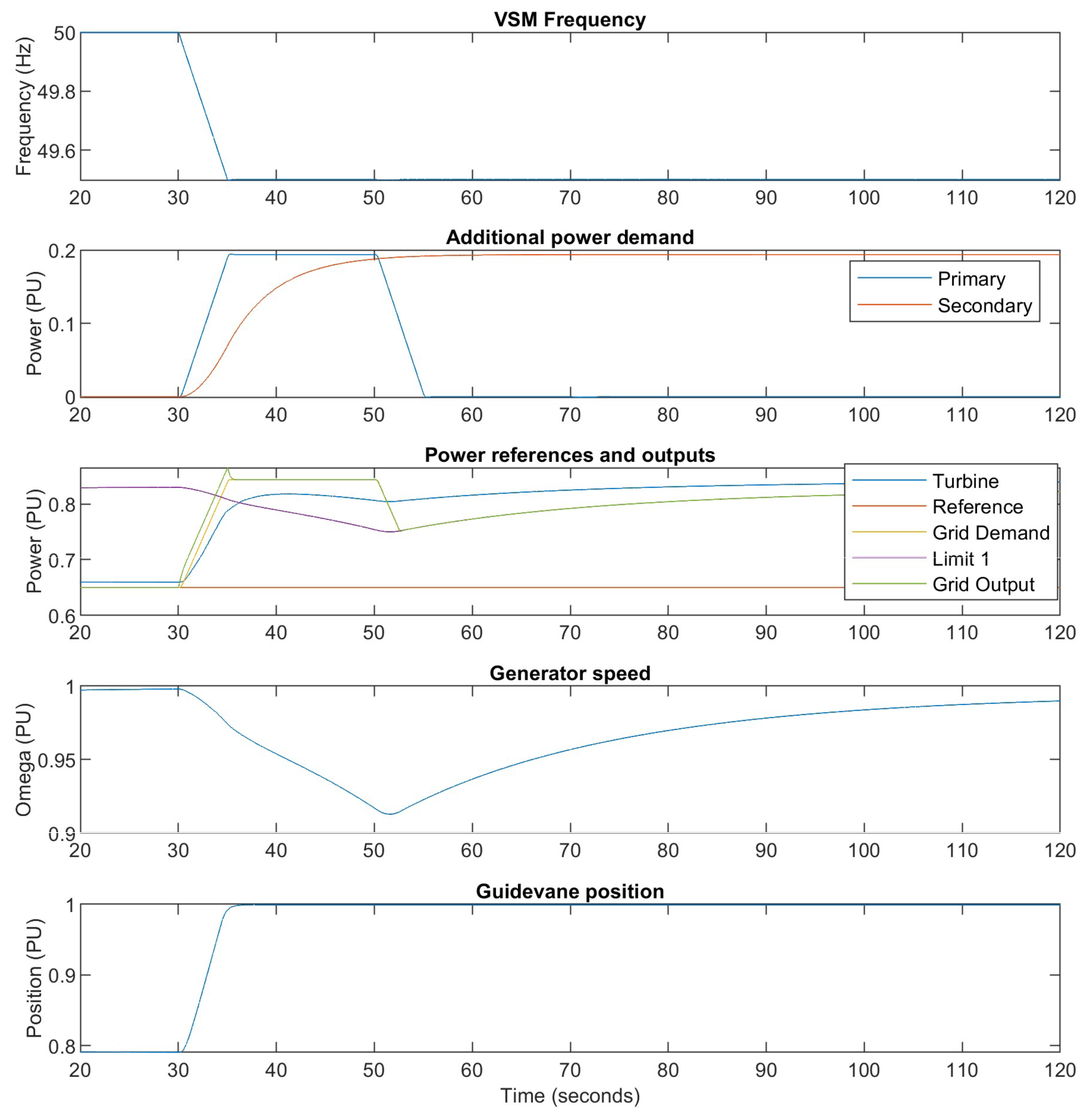
The Frequency Support Control tests for the stiff grid model are shown in
Figure 28. In this test, the grid frequency is dropped from 50 Hz to 49.5 Hz within slightly over 5 s and remains at the dropped value. Droops, both primary and secondary, are set to 0.2 p.u. The power reference is taken as 0.65 p.u. (shown in orange in the second part of the figure).
The primary response starts as the grid frequency begins to fall and is provided using the inertia of the turbine, which slows it down and decreases the generator speed. As a result, the governor opens the guide vanes, and the speed starts to recover.
Meanwhile, the excess synthetic inertia in use produces a power output for the grid that is higher than the reference value. However, this is limited by the
(shown in purple in the
Figure 28) to allow a smooth turbine speed recovery.
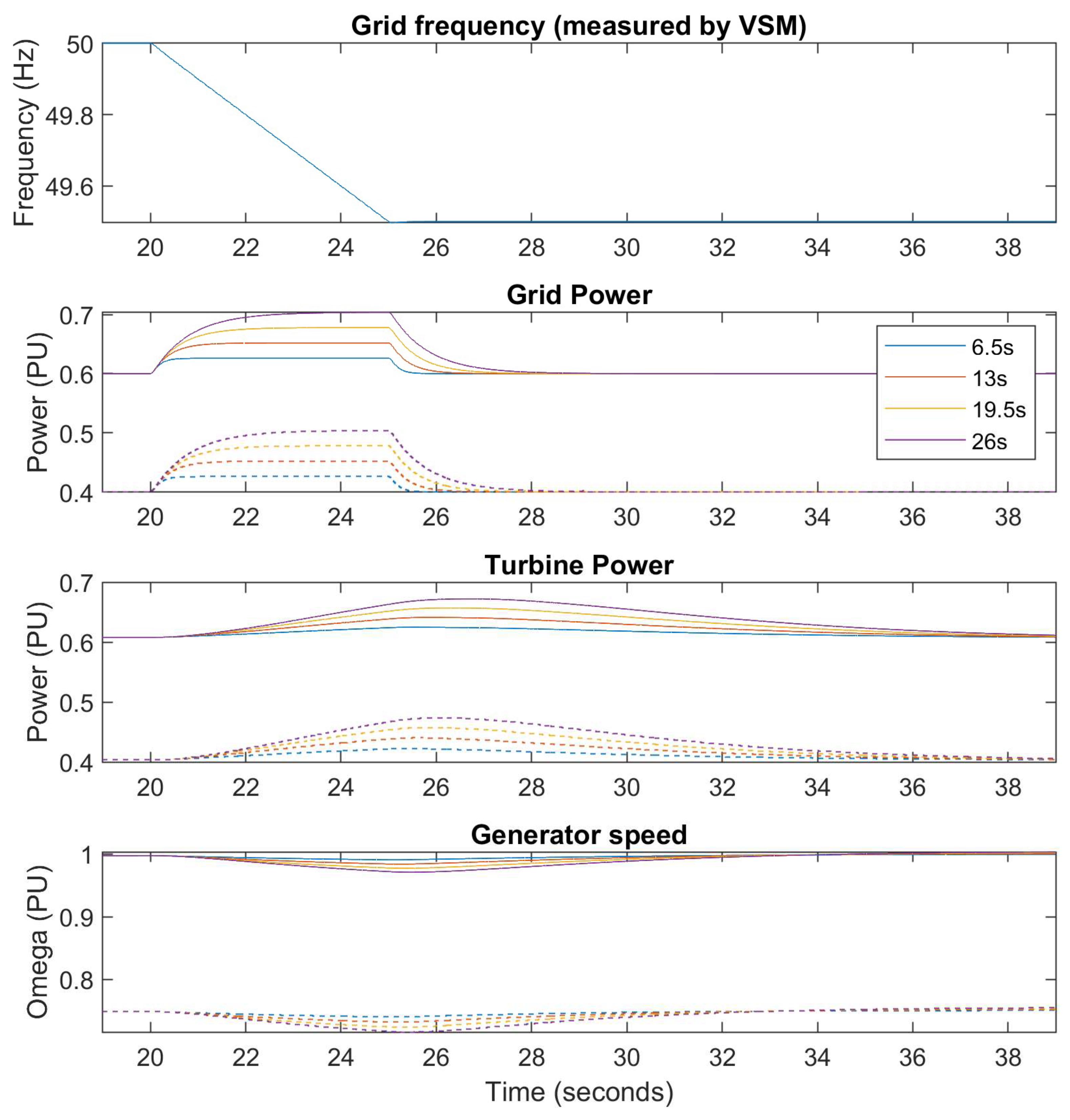
In
Figure 29, synthetic inertia provision is demonstrated for several virtual inertia constants from 6.5 s to 26 s. Solid lines mean
rated power and
rated turbine speed, whereas the dashed lines indicate
rated power and
rated turbine speed. Furthermore, the grid frequency is dropped exactly as in the previous test. The simulations show that the synthetic inertia response is swift. As the inertia is drawn from the turbine and the generator, the generator speed decreases, which is once again compensated by the governor.
Operating the generator at a lower rated speed and power (dashed values) does not create a significant difference. A higher dipping would be expected, but there is greater power headroom at lower-rated power, allowing a faster turbine response that balances the lowered operating conditions. To sum up, results show that the provision of different levels of synthetic inertia is possible. However, the amount of inertia that can be provided depends on the rated speed and power values, which might be limiting, especially for sharper frequency dips. Thus, VSHP may need to balance the inertia provision based on the expected generator payment.
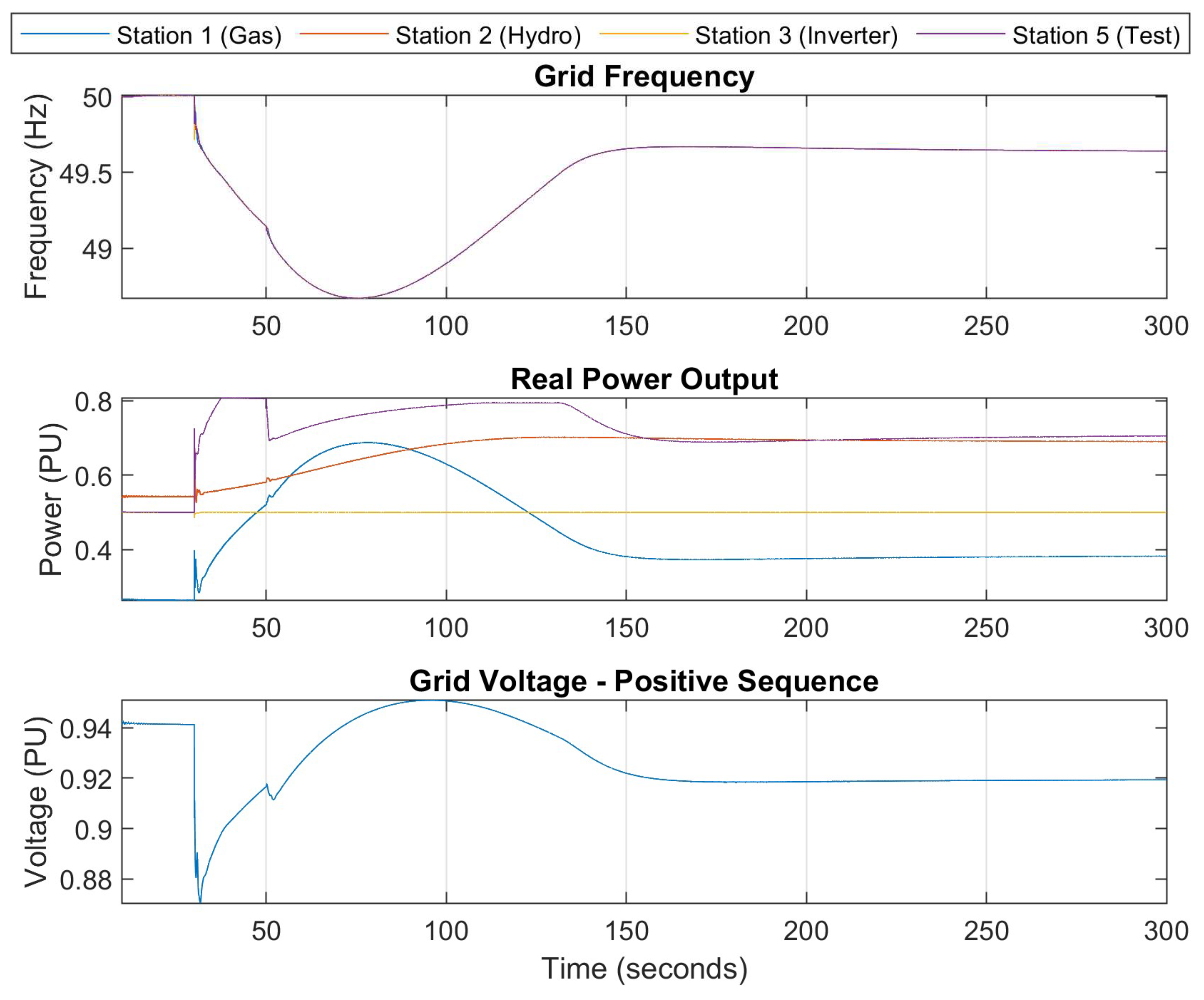
Finally, the representative grid tests whose parameters were given in
Table 9 are performed. For this, three cases are considered: the fixed-speed system for station 5, and the variable-speed systems using the VCC and VSM. In
Figure 30, the response of the variable-speed system with VSM is expanded, which is then compared with the fixed-speed system and the variable-speed system with VCC in
Figure 31. As the grid frequency starts to drop, the stations start to respond. The gas station responds the swiftest, the inverter provides a constant power output (HVDC link), the hydro responds at a slower rate, and station 5 is either the fixed-speed system or the VSHP. The VSHP provides a better response by reducing the rate the frequency drops and stabilising much faster. The VCC and VSM perform similarly, with a minimal reduction in the frequency observed for the VSM.
4. Discussion
This paper has presented a comprehensive control approach that improves the fault ride-through performance and ancillary services for VSHP. Additional benefits from advanced control strategies such as MPC have been gained. The frequency response of the system and the grid stability were tested for various conditions. The outputs of this extensive analysis can be summarised as:
Integrating the VSM/VCC with the grid-side converter enabled the effective simulation of the generator inertia provision. It enhanced the damping characteristics and thus has been observed to stabilise the system further during frequency deviations.
The frequency disturbances that hinder grid stability have been mitigated by the effectiveness of the Frequency Support Controller in keeping the grid frequency within desirable limits.
The anti-windup PID and MPC controllers have performed well on the turbine governor side. However, the MPC has outperformed the PID controller by providing faster and smoother transient response with lower rise times and overshoots.
The simulations have been performed on a stiff grid and a representative grid model that resembles the Nordic grid power mix. Several scenarios verifying the proposed control strategy have been considered. For instance, the frequency dip during loss-of-generation events has been damped due to the efficient synthetic inertia provision, showing the potential of the proposed control approach to provide grid stability.
The research shows the potential of VSHP technology for grid stability and flexibility. This aligns with the increasing demand for renewable energy sources to provide ancillary services and support in transitioning towards a more resilient and sustainable grid.
Future studies could consider accommodating the requirements and needs of different regions of the world. For example, a grid model with highly varying and more intense renewable energy penetration could be tested. Alternatively, utilising a VSHP simultaneously with energy storage systems might be a research idea worth investigating.
From the control perspective, validations of the methods in the paper on a real-world VSHP application could provide important research outputs in terms of understanding the practical limitations. In the shorter term, designing a non-linear version of the MPC or a linear-parameter varying version will be considered in order to improve the turbine governor performance.
Finally, a high-level optimisation approach could be investigated for handling the management of ancillary services and the internal management of VSHP, paying attention to aspects like extending the turbine life-span. Optimisation of these economic aspects, along with successful field validations, could incentivise future investments.


