Article

Dual-Stage Energy Recovery from Internal Combustion Engines

by
Davide Di Battista
*,
Federico Di Prospero
,
Giammarco Di Giovine
,
Fabio Fatigati
and
Roberto Cipollone
Department of Industrial and Information Engineering and Economics, University of L’Aquila, P.le Pontieri 1, 67100 L’Aquila, Italy
*
Author to whom correspondence should be addressed.
Energies 2025, 18(3), 623; https://doi.org/10.3390/en18030623
Submission received: 22 December 2024 / Revised: 16 January 2025 / Accepted: 27 January 2025 / Published: 29 January 2025
(This article belongs to the Special Issue Advances in Waste Heat Recovery and Integrated Energy Systems)

Abstract

:
Waste heat recovery is one of the most investigated solutions for increasing the efficiency of powertrains in the transportation sector. A major portion of thermal energy is wasted via exhaust gases. Almost one third of fuel energy is lost, and its recovery as propulsion energy is a promising goal. Moreover, this enables the increased electrification or hybridization of powertrains, assuming the energy recovered is converted into electrical form and used to fulfill different vehicles’ needs. The present study focuses on a dual-stage energy recovery system designed to enhance the efficiency of internal combustion engines (ICEs) in heavy-duty vehicles (HDVs). The system combines a turbocompound unit for direct heat recovery (DHR) and an organic Rankine cycle (ORC) for indirect heat recovery (IHR). These technologies aim to exploit waste heat from exhaust gases, converting it into electrical energy. In this regard, electrical energy can be stored in a battery for it to be available for the energy needs of powertrains that use hybrid propulsion and for driving pumps and compressors on board, following recent technologies of auxiliaries on demand. The proposed setup was modeled and analyzed under off-design conditions to evaluate energy recovery potential and engine performance impacts. From this point of view, in fact, any device that operates on exhaust gas introduces a pressure loss, increasing engine backpressure, whose effect is an increase in specific fuel consumption. An estimate of this negative effect is presented in this paper based on experimental data measured in a F1C IVECO™ engine. An average net recovery of 5–6% of engine power has been demonstrated, with an important prevalence of the turbocompound with respect to the ORC section. The results demonstrate the viability of integrating DHR and IHR stages, with implications for advancing sustainable transportation technologies.

1. Introduction

Human society has been living in an ecological transition era, where human behaviors should be changed to face the climatic emergency. This is mainly related to greenhouse gas emissions, which are mostly linked to energy consumption [1]. All economic sectors are involved, and the transportation sector ranks as the second most energy-intensive one globally, being responsible for approximately 27% of primary energy consumption, largely due to its reliance on fossil-fuel-based propulsion systems [2]. Within this sector, on-road vehicles for passenger and freight transport account for the largest share, and these vehicles are currently undergoing a transformative period where traditional internal combustion engines (ICEs) are increasingly being accompanied by electric and hybrid powertrains [3,4]. This shift is significantly altering driving habits, particularly for private passenger cars, while posing unique challenges for heavy-duty vehicles (HDVs) used in freight and passenger transit.
This growing awareness of the environmental impact from fuel consumption and emissions, combined with global carbon reduction commitments shared by international governments, drives the need for innovative vehicle technologies with reduced environmental impact. Recently, the European Union updated its emission regulations for HDVs [5,6], and other countries are also setting targets for their transportation sectors to reduce their environmental impact [7]. In this regard, the full electrification of HDVs remains challenging in the short term, while strategies that enhance efficiency and lower emissions without completely abandoning conventional powertrains are essential and can have a crucial role in this transition period [8]. Alternative fuels [9,10], such as biofuels [11], methanol [12], and e-fuels [13], show promising results, though there are still concerns around their full life cycle impacts [14]. Hydrogen-fueled ICEs are under exploration as well, leveraging hydrogen as a cross-sector energy carrier [15]. However, challenges related to hydrogen’s predominantly fossil-based production and infrastructure development constrain its short-term viability. Fuel cell powertrains have also been developed [16], yet they face similar infrastructure and life cycle hurdles [17].
As a result, the most promising technologies for HDVs are those that reduce fuel consumption with minimal costs and ease of integration into existing systems. HDV ICEs, which are less impacted by transient driving phases, already exhibit high efficiency, making further improvements particularly challenging. Among the various approaches, waste heat recovery (WHR) for both conventional and hybrid powertrain applications has drawn significant attention, where recovered energy can be stored in batteries and made available for use in auxiliary electrification [18,19]. For instance, in the US Supertruck program, waste heat recovery (WHR) systems are being considered to achieve engine efficiency targets; in the third stage of the program, the electrification of all sizes of HDVs was proposed [20].
Waste heat recovery for ICEs can be achieved via two main methods: direct heat recovery (DHR) and indirect heat recovery (IHR) [21]. DHR uses exhaust gases directly as the working fluid, often incorporating an additional turbine in the exhaust system, also known as turbocompounding [22]. This approach offers substantial power recovery, and different applications in marine and heavy-duty engines have been developed [23,24]. In mechanical turbocompounding, the secondary turbine is mechanically coupled to the engine crankshaft, often through a gearing system. This setup transfers the recovered energy directly to the engine, increasing the overall power output without additional fuel consumption [25,26]. On the other hand, electrical turbocompounding involves coupling the secondary turbine to an electrical generator instead of the crankshaft. The electricity produced by the generator can be used to power other engine systems, stored in a battery, or used to drive an electric motor in hybrid powertrains. This approach increases flexibility and can improve overall system efficiency, particularly in hybrid and electric vehicles [27,28]. The integration of a turbocompound into engine systems is very important, since the major disadvantage of this technology is increased exhaust backpressure, which results in higher pumping loss in the engines [29]. The additional turbine efficiency plays an important role, in particular if a conversion chain into electrical form is considered [30]. Moreover, the opportunity to have variable-geometry and variable-speed turbines allows for a more efficient turbocompound in different operating conditions [31,32]. An integrated control strategy for injection and valve timing, combustion, boosting, and exhaust heat exploitation can solve related issues [33] under certain operating conditions. In addition, advancements such as the inverted Brayton cycle (IBC) have been proposed, enabling sub-atmospheric pressure expansion but with increased complexity due to additional components (compressor and large cooler) [34,35,36].
In contrast, IHR employs a separate working fluid, enabling the use of various engine heat sources beyond exhaust gases, such as coolant and oil. Organic Rankine cycles (ORCs) are commonly used for IHR, where an organic fluid transforms waste heat into mechanical energy, performing a Rankine thermodynamic cycle [37,38,39]. ORC units are under extensive consideration for energy recovery due to their reliability, adaptability, and stable performance [40]. Despite these benefits, the frequent and wide fluctuation of the waste heat (i.e., exhaust gases) involves considerable challenges for the control of ORC-based units under dynamic conditions [41]. Indeed, although prototypes exist, market adoption has been limited by the low efficiency and challenges of off-design performance. Proposed solutions for improving ORC efficiency include more complex circuits with regenerative branches and secondary loops [42], as well as cascade cycles with supercritical CO2 [43,44] and expander supercharging [45,46], though the expander remains a critical component [47,48].
In this study, a combined waste heat recovery system is introduced. A supplementary turbine is added to the exhaust line of a turbocharged ICE downstream of the turbocharger. This component is integrated with an engine model to assess power recovery under off-design conditions. Additionally, the impact of increased backpressure on engine performance, which may cause higher fuel consumption or lower torque, is evaluated against the power recovered through turbocompounding. The results also consider the implementation of a second IHR downstream of the DHR turbine, based on an ORC system. The ORC is represented with an experimentally based model that is able to catch the real performance of the recovery unit under several exhaust gas conditions (temperature and mass flow rate). The feasibility of the dual stage is demonstrated under several engine working points, and the overall energy recovery is assessed. The model is applied to the exhaust gases of a turbocharged diesel engine (IVECO™ F1C engine) that has been extensively tested on an engine test rig, in steady and unsteady conditions. The testing activities measured all the parameters (flow rate, temperature, and pressure) that characterize the exhaust line of the referenced engine. The experimental activity also involved the evaluation of the effect of the pressure increase at the exhaust produced by the devices related to DHR and IHR. This is the case with the turbocompounding unit itself and the heat recovery vapor generator (HRVG). The turbocompounding section is the most important in terms of power recovered: it accounts for 75–80% of the overall power, which is on average 9–10% of the engine power in a specific test case. The final net power recovered, considering the engine loss due to the backpressure effect, is about 5–6% of the engine power in the operating region considered.

2. Materials and Methods

The layout for the energy recovery section is shown in Figure 1. A reference engine, namely, IVECO™ F1C 3.0 L present on a test bench in the ICE lab of University of L’Aquila, was selected for preliminary data collection and model development [49]. In its category, it is a reference engine, since it equips some light commercial vehicles and also military and marine vehicles. It has a variable-geometry turbocharger, which allows for a wide operating range and the possibility for the engine to be adapted to different vehicle platforms. Indeed, in the ECU, it has two different settings, for light-duty and heavy-duty vehicles, demonstrating the high flexibility and range of operation. Regarding efficiency, this falls into the category of common diesel engine vehicles (20–35%), and therefore, the same considerations apply for waste heat availability (i.e., exhaust temperature and mass flow rate), which is roughly one third of the fuel power. This engine has been widely tested in previous works [34,49]. The engine test bench is a dynamic one, with the possibility of measuring all the relevant engine parameters. The engine room was environmentally conditioned in order to keep the testing conditions in a suitable range to assure the repeatability of the tests.
To maintain the proper operating temperature for these components, the recovery section can be positioned downstream of the turbocharger and aftertreatments. The reference temperature, pressure, and mass flow rates of the engine are presented in the following sections and are used as boundary conditions for designing the auxiliary turbine [29]. After sizing the auxiliary turbine (Taux), it was analyzed under off-design conditions to explore all operating points of the engine, and the final energy recovery was assessed. At the same time, the ORC section was placed downstream of the turbocompound section. It has previously been properly studied thanks to an experimentally validated model in off-design conditions [50].
The model integration began with the engine exhaust data, particularly exhaust mass flow rate, pressure, and temperature, which were used as boundary conditions for the first stage of recovery, namely, the turbocompound. This submodel can be solved to assess the electric power recovered and the downstream exhaust temperature. These data, along with the exhaust mass flow rate, are needed to solve the second-stage ORC model. The final net electric power was calculated and compared to the estimation of the engine power loss in relation to the backpressure produced by the turbocompound.
The flow diagram in Figure 2 outlines the interactions between the engine exhaust parameters and the recovery system components. It captures the dynamics of exhaust flow, temperature, and pressure, serving as basis for the computational model used in analyzing system performance under various operational conditions.

2.1. Direct Recovery Modeling

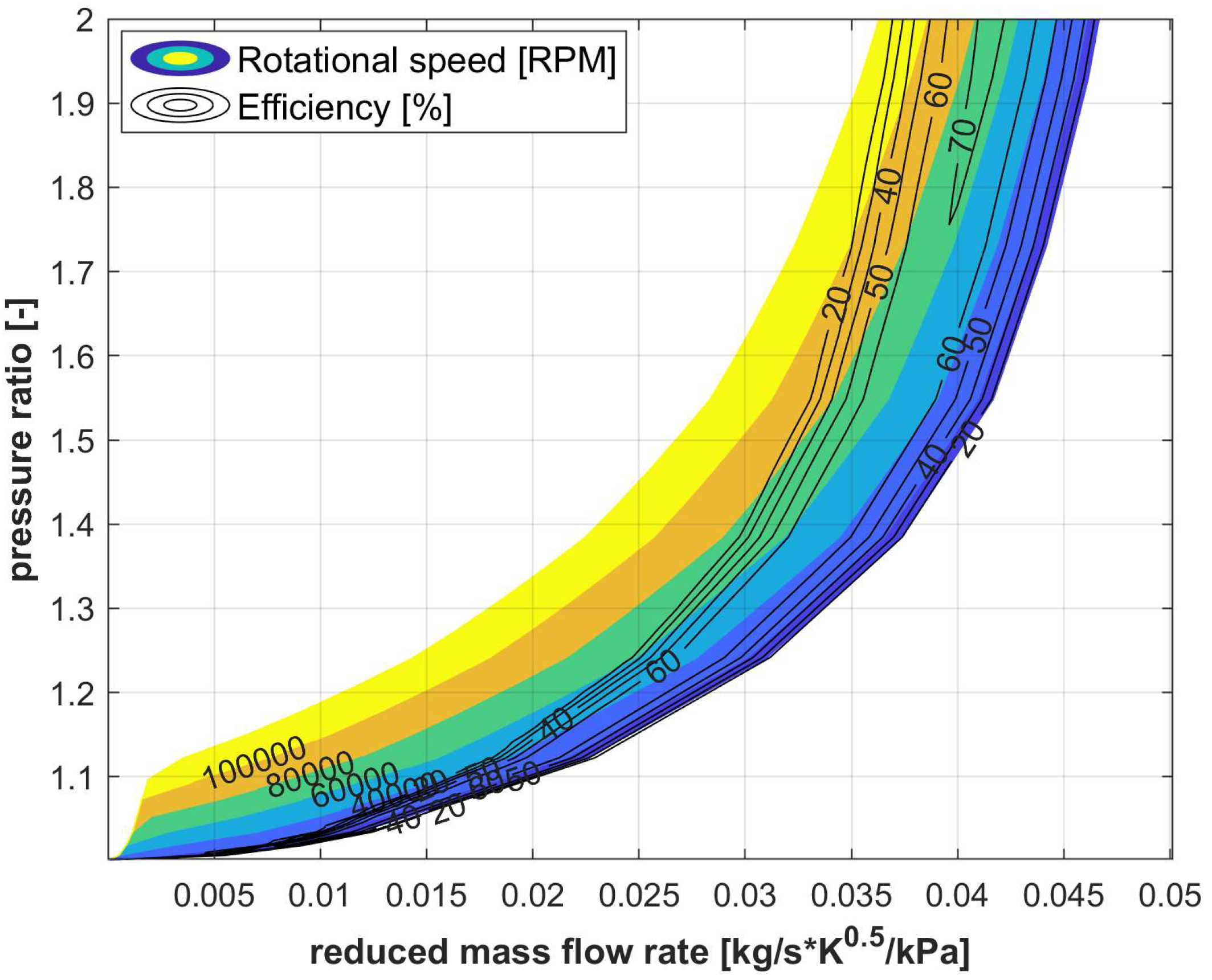
The direct heat recovery section was developed by deriving a radial auxiliary turbine from the existing one of the engine [29]. Indeed, the same mass flow rate crossed the auxiliary turbine in series with the turbocharger one. Only thermodynamic conditions should be adapted to properly size the turbocompound. A map-based approach was utilized, where the performance of the turbine is represented in terms of reduced mass flow rate, pressure ratio, rotational speed, and efficiency (Equation (1)).
m r e d = m e x h T e x h p e x h β T C = p e x h p o u t , T C η T C = m e x h h e x h h o u t , T C m e x h h e x h h o u t , a d , T C
Figure 3 depicts the performance characteristics of the auxiliary turbine, showing its efficiency and output across varying operational conditions. It provides insights into the turbine’s adaptability to changes in exhaust mass flow and temperature, which are critical for maintaining energy recovery efficiency without adversely impacting engine performance. The pressure ratio values did not exceed 1.9, since the device was placed in the very last part of the exhaust line, close to the exhaust outlet. This is also important for reducing the backpressure effect as much as possible, which reduces the efficiency of the engine, increasing pumping losses. Rotational speed assumes characteristic values for small radial turbines in the automotive sector, the maximum value being around 110 kRPM. This parameter was considered freely variable during operation in order to optimize efficiency: the rotational speed can be seen as the regulating parameter of the turbocompound. The range of operation as shown in Figure 3 suggests the use of a conventional radial turbine, very similar to that of the turbocharger, mainly scaled to match the thermodynamic inlet quantities. The overall efficiency is in the range between 50 and 70% for most parts of the operating region of the turbocompound, with a maximum value of about 73%. However, the size of the turbocompound is a legitimate issue, since it influences the specific performance of the turbine, backpressure effect, final recovery, as well as the technological constraints of having a high-speed electrical generator. Hence, the correct sizing of the turbocompound could enhance or reduce the energy recovery from the first section. However, the use of similarity theory (reduced mass flow rate, pressure ratio, and thermodynamic speed as in Figure 3) can ensure the scalability of the component.
An electric conversion section should be considered, since the energy recovery will be likely converted into electrical form to be utilized on board for vehicle auxiliaries or to be stored in a battery.
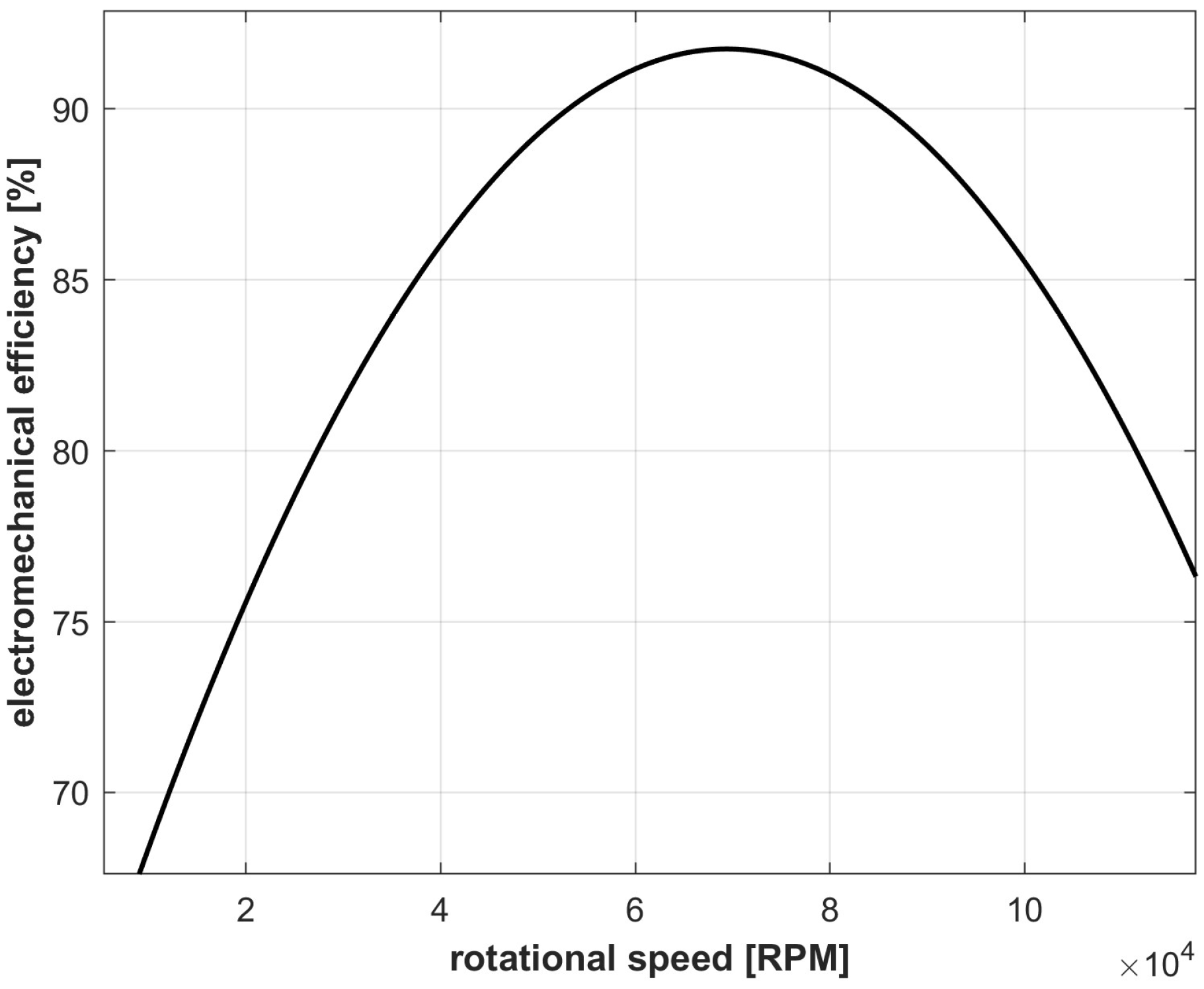
Figure 4 demonstrates the efficiency of an electric generator across different load conditions, based on experimental values of a specific machine for high-speed devices (up to 100 kRPM) [51]. The reported efficiency considers both the thermodynamic-to-mechanical conversion and the mechanical-to-electrical one, as this concerns a single device (an electric generator coupled to a radial turbine). Understanding this efficiency curve is pivotal for evaluating the net energy conversion rates and the overall feasibility of the direct recovery system, as the generator performance directly affects the energy output.
Figure 5 shows the relationship between the backpressure introduced by the auxiliary turbine and the resultant engine power losses. This visualization is crucial for balancing energy recovery benefits against potential drawbacks such as increased pumping losses, which could compromise overall engine efficiency if not carefully managed. A specific experimentally based approach has been considered, which quantifies the reduction in engine efficiency and the increase in engine specific consumption in relation to the pressure rise in the exhaust line produced by the presence of the turbocompound [29]. Indeed, the additional turbine is seen as an additional pressure drop by the engine, and this effect produces increased pumping work in the indicated cycle. In order to keep the same power output, the engine control unit should increase the fuel rate, which, in turn, increases the specific fuel consumption (ΔSFC). The possible mitigation of the variable-geometry turbine control strategy, which controls the air/fuel ratio, has been also integrated in this approach [34]. The backpressure value of Figure 5 is related to the pressure ratio of the turbocompound (Figure 3).

2.2. Indirect Heat Recovery Section

The indirect heat recovery section includes an ORC (organic Rankine cycle)-based unit, which is represented by an experimentally validated model. This model was developed using a combined zero-dimensional (0D) and one-dimensional (1D) approach [52,53]. The primary flow paths were modeled as single ducts and manifolds, where energy, momentum, and continuity equations were solved numerically using a discretized approach. For each component, scalar properties such as pressure, temperature, density, internal energy, and enthalpy were assumed to be uniform within each sub-volume, while vector variables like mass flow rate, velocity, and mass fractions were calculated at the boundaries. The 1D conservation equations were solved using an implicit numerical method [52]. The thermodynamic properties of the organic fluid were obtained from the NIST Refprop™ database [54].
The key components of the system include the pump (Section 1–2 in Figure 6), the evaporator (Section 2–3 in Figure 6), the expander (Section 3–4 in Figure 6), the condenser (Section 4–1 in Figure 6), and a 3 L tank serving as a receiver upstream of the pump. These components form the boundary conditions for the connecting pipes and are modeled accordingly. Specifically, the pump and expander are treated as lumped objects, while the heat exchangers are divided into multiple sub-volumes using a staggered grid approach [55]. The pump is a gear rotor type, while the expander is a scroll one [56], which ensures high flexibility of operation, reliability, and easiness of maintenance. The evaporator uses the exhaust gas energy to heat, vaporize, and superheat the organic working fluid (R245fa in the experimental apparatus), which operates at the maximum pressure level (pORC,max). On the other hand, in the condenser, the cold source is represented by the water flow available on board at a suitable temperature (40 °C [49]), and consequently, the condensing pressure (pORC,min) was determined. A model-based control was introduced to optimize the behavior and to preserve the integrity of the working fluid [50].
The ORC model, then, was completed with calculations of the main result parameters, as in the systems of Equation (2). The heat recovered, Qrec, is calculated from the exhaust gas side, where the exhaust inlet temperature at the evaporator, Texh,in, is the one exiting from the turbocompound and resulting from the specific submodel. Hence, the organic working fluid mass flow rate, mwf, and, consequently, all the thermodynamic powers exchanged across components (pump, expander, and condenser), can be calculated. The electric power absorbed by the pump, Ppump,el, and delivered by the expander, Pexp,el, was evaluated knowing the values of the overall electric efficiency of the two components (ηexp and ηpump). The ORC thermodynamic cycle efficiency, ηcycle, was evaluated as well to have an idea of the thermodynamic behavior of the recovery unit. The net power recovered, Pu,ORC, was evaluated considering the electrical values to have the final power that can be used for vehicle purposes or stored in a battery.
Q r e c = m e x h c p , e x h T e x h , i n T e x h , o u t m w f = Q r e c h 3 h 2 P e x p , e l = m w f h 3 h 4 η e x p P p u m p , e l = m w f h 2 h 1 η p u m p η c y c l e = h 3 h 4 h 2 h 1 h 3 h 2 P u , O R C = P e x p , e l P p u m p , e l
The model was experimentally validated under dynamic working conditions [53]. In particular, the model was able to reproduce the ORC-based power unit’s transient behavior for a step variation in ICE operating conditions (torque and speed). It was found that the model is able to reproduce, with good accuracy, the time evolution of the main operating quantities (maximum pressure and temperature) and plant performance. It was found that the absolute standard deviation of the maximum pressure and temperature equals 0.1 bar and 0.11 °C, respectively, within the experimental uncertainty range. For what concerns the power produced by the plant, the root-mean-square error is equal to 7 W. More details about the experimental validation section can be found in [50,53].
The plant control is based on the regulation of the working fluid mass flow rate, which is the main regulating parameter for the plant as observed in [55]. In fact, for the adopted plant layout, the expander speed is not externally imposed but depends on the dynamic equilibrium between the driving and resistant torque. It was found that a proportional regulation takes place between the working fluid mass flow rate and expander maximum pressure. Such a relation depends on the plant’s permeability, which explains the capability to be crossed by the working fluid. The lower the permeability, the larger the expander pressure is for a given working fluid mass flow rate sent by the pump. Permeability can be used as the base for a proportional regulator to modify the pump speed, and consequently the working fluid mass flow rate, to achieve the desired value of maximum pressure [57]. This value was evaluated according to the heat source conditions (temperature and working fluid mass flow rate). Indeed, through the energy conservation equation, the working fluid mass flow rate ensuring a superheating degree at the expander inlet close to 20 °C was evaluated (in optimal expander inlet conditions). The working fluid mass flow rate was refined through proportional feedback regulation based on the linear relationship between maximum pressure and working fluid mass flow rate. The control section ensures that the temperature does not exceed the fluid chemical decomposition value, which is set at 160 °C. This does not represent an issue for the components’ material, since the temperatures of both exhausts and organic fluid can be compatible with common materials for heat exchange (steel, cast iron, etc.).
Thanks to a detailed model of the unit developed in a GT-Suite® environment [53], the automatization of the control system was assessed, and the difference between this and the case in which no control action was adopted was analyzed. It was found that, for a sequence of sudden variation in hot source conditions, the controlled ORC-based power unit can keep the maximum temperature below 160 °C (decomposition limit). In fact, an uncontrolled ORC plant cannot satisfy this issue. Moreover, the control system prevents a situation in which the two-phase working fluid is processed by the expander. As a matter of fact, a superheating degree close to 20 °C is ensured, leading to a stable power production between 1 and 2 kW, with a corresponding efficiency of 4–6% under severe transient conditions.
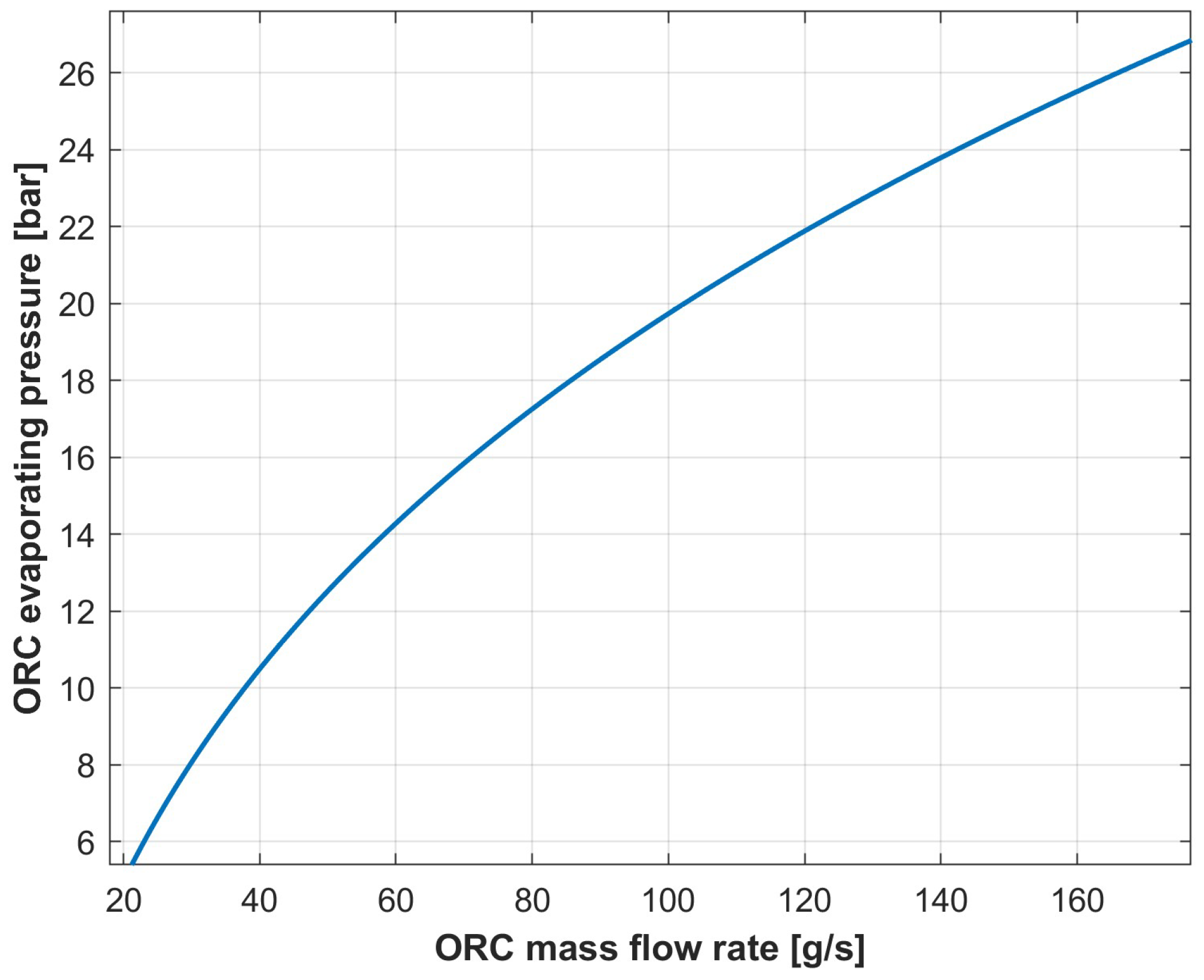
Figure 7 illustrates the operating parameters of the ORC unit, emphasizing the correlation between the evaporating pressure, pORC,max, and the fluid mass flow rate, mwf. These parameters are instrumental in describing the real hydraulic behavior of the ORC circuit and in optimizing the control strategy for maximum energy recovery efficiency.
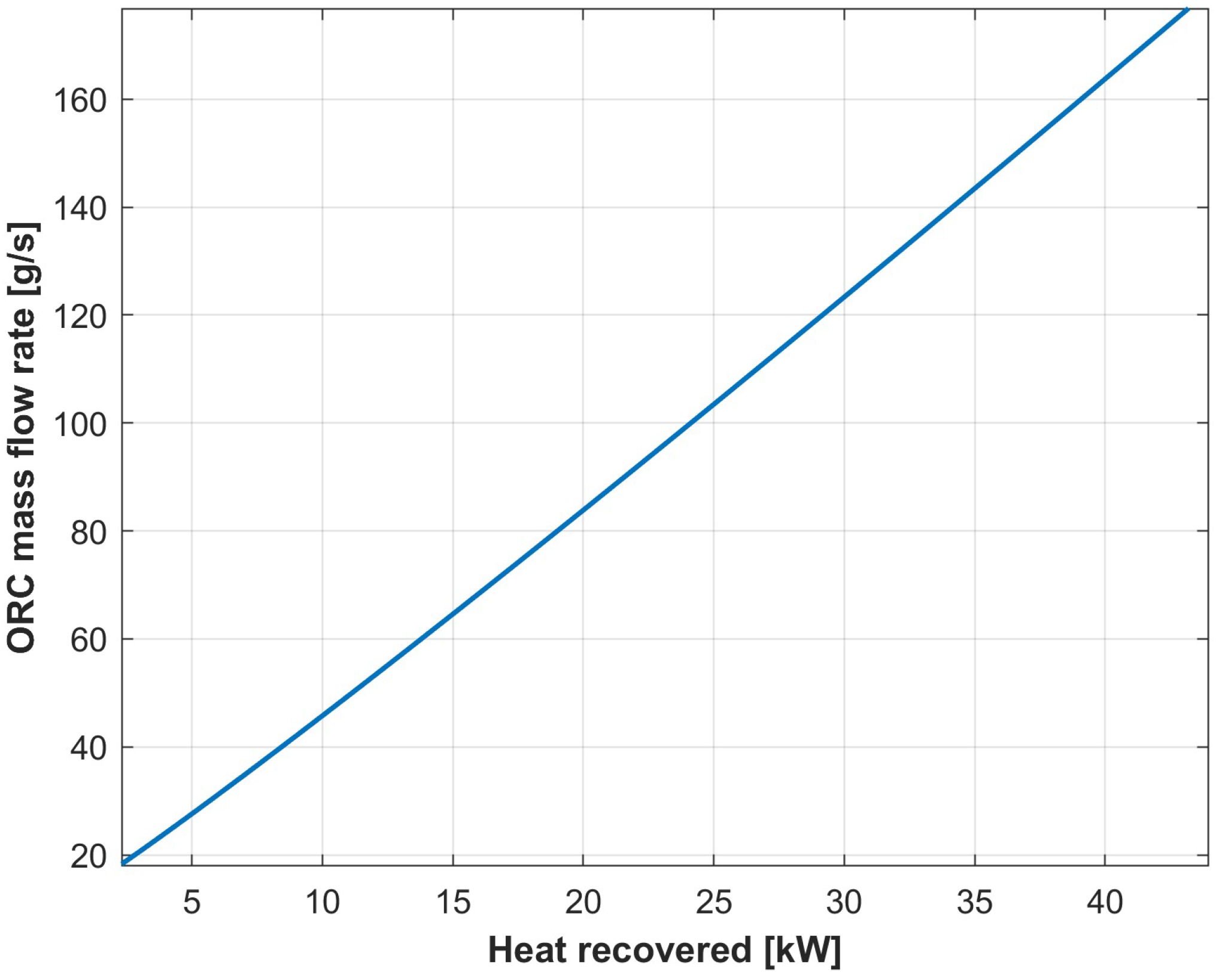
Figure 8 shows the organic fluid mass flow rate mwf as a function of the heat recovery capabilities Qrec of the ORC system. It demonstrates how adjustments in fluid circulation can directly influence the system’s ability to harvest waste heat effectively. The trend is almost linear, with a maximum mass flow rate of 170 g/s corresponding to thermal power recovered close to 45 kW.
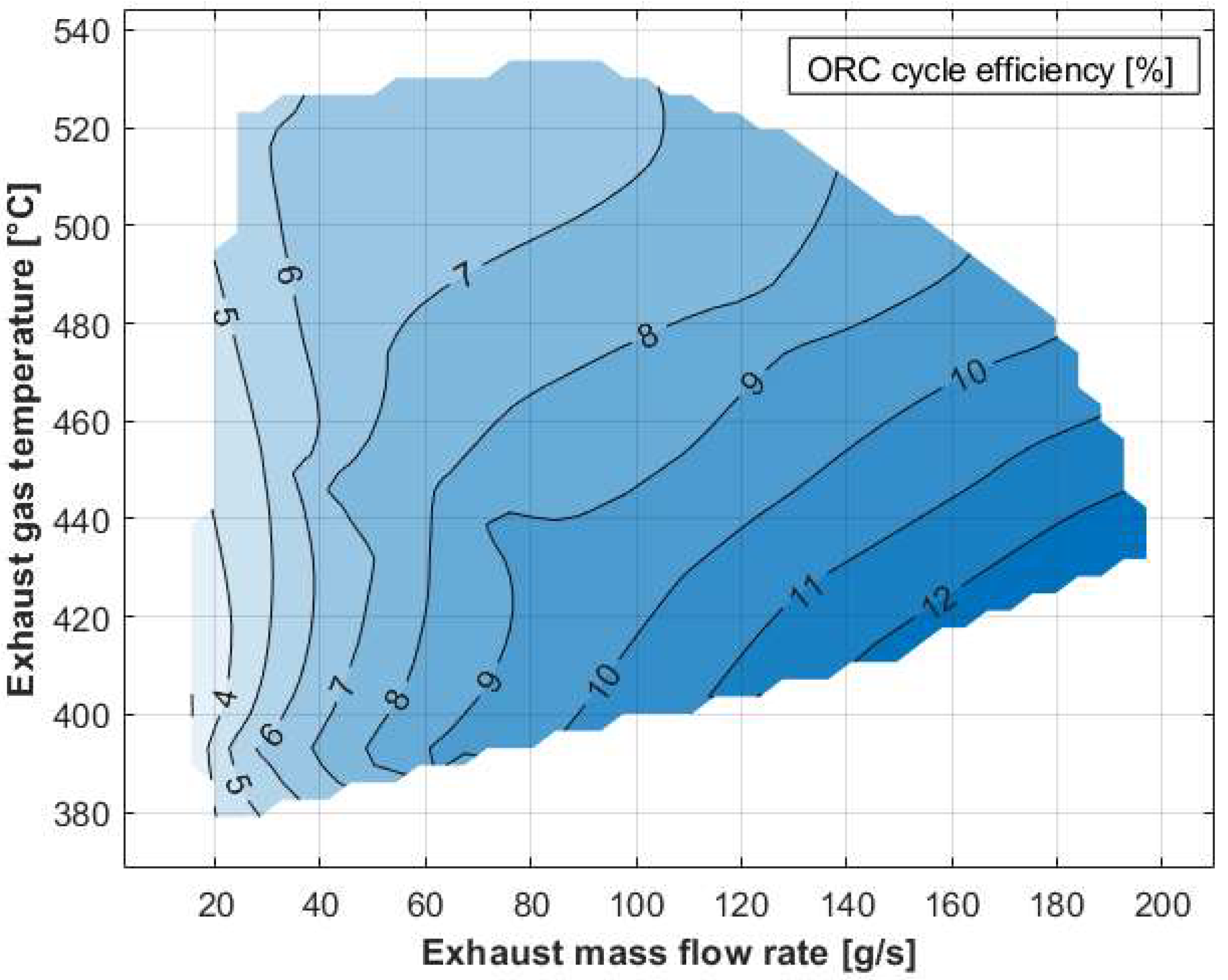
Figure 9 presents the thermodynamic cycle efficiency, ηcycle, of the ORC system in relation to the temperature and mass flow rate of exhaust gas entering the evaporator. The data underline the importance of inlet conditions in achieving peak cycle performance, which is strictly related to ORC pressure levels. Values up to 12–13% were obtained, demonstrating also the optimization of the control strategy proposed.

3. Results

This modeling approach has been used to assess the overall performance of dual-stage waste heat recovery bottomed to an existing turbocharged diesel internal combustion engine. Hence, the turbocompound is directly bottomed to the exhaust section of the turbocharger, while the ORC unit is placed downstream of the turbocompound. Each subsection has been considered in the results, before combining the two values of power recovered and comparing them with the estimated engine backpressure losses.
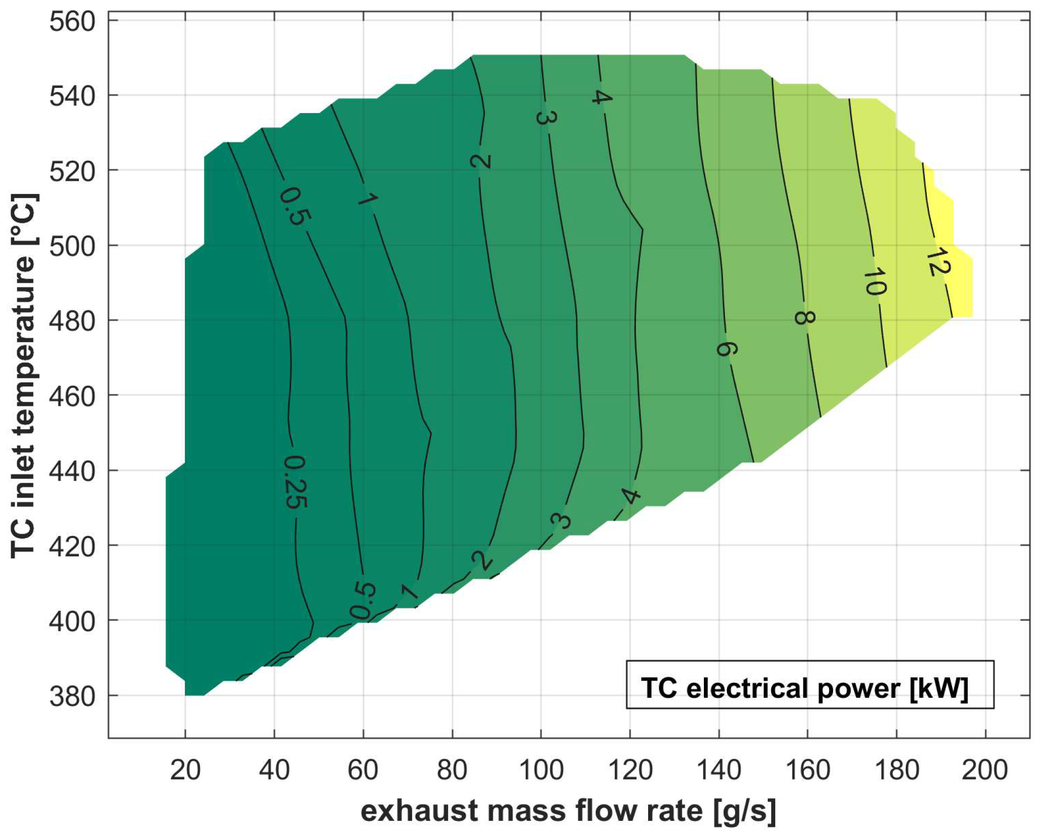
Figure 10 quantifies the electrical power generated through the turbocompound system under various exhaust operation scenarios. It is above 12 kW, mainly increasing with exhaust mass flow rate.
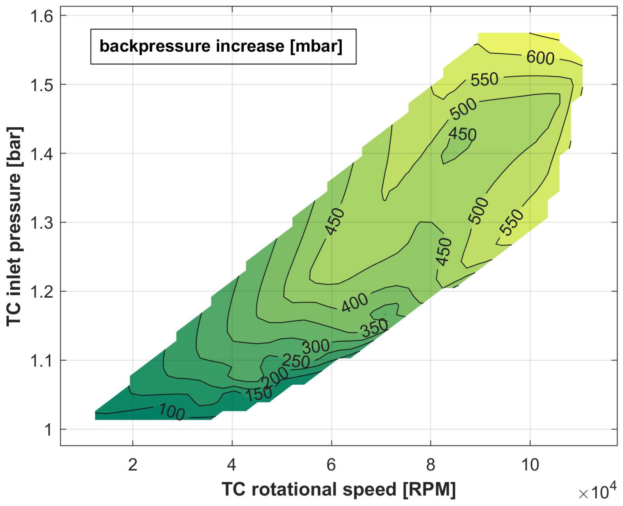
Figure 11 emphasizes the backpressure produced by the presence of the turbocompound in the exhaust line [29]. In fact, any component placed in the exhaust line would be an “obstruction” for the exhaust to overcome. This produces an increasing value of the engine exhaust pressure, which reduces the engine efficiency. In reality, the evaporator of the ORC bottomed to the turbocompound also produces pressure drops in the exhaust side. However, if a proper technology is considered, this effect can be neglected with respect to that of the turbocompound. The values of Figure 11 derive from an experiment conducted on the reference engine. They depend on inlet pressure and the rotational speed of the turbocompound, which reaches 110 kRPM. An optimized control strategy for this parameter can reduce this detrimental effect [33].
The temperature of exhaust gases exiting the turbocompound stage reveals the residual heat available for the ORC unit. It is related to the enthalpy drop across the auxiliary turbine and, thus, the mechanical power recovered, as well as the engine exhaust temperature (i.e., the turbocompound inlet one). This information is valuable for assessing the compatibility and integration potential of the dual recovery stages (Figure 12), and it is used as boundary condition for the bottomed ORC unit.
Once the temperature and mass flow rate of the exhaust gases exiting from the first recovery stage are evaluated, the second stage (ORC unit) can be considered and its performance calculated.
Figure 13 highlights the ORC system’s ability to recover heat as a function of exhaust gas parameters. It underscores the interplay between gas temperature, mass flow rate, and the heat recovered in the evaporator, guiding the final net recoverable power of the second stage. Up to 40 kW of thermal power is recovered, increasing with exhaust mass flow rate and temperature, as expected.
Therefore, the net power output of the ORC unit can be calculated and is represented in Figure 14. Its value approaches 2 kW in optimal conditions (higher mass flow rate and temperatures). This is an experimentally based value and considered the total conversion efficiency of the thermal machines (pump and expander) in terms of conversion into and from electrical form, as well all the circuit constraints related to hydraulic permeability and the effectiveness of the heat exchangers. Indeed, the maximum net overall efficiency, calculated as the ratio between the net electrical power and the heat recovered, is approximatively equal to 5%, compared to a thermodynamic cycle efficiency of 13% (Figure 9).
Finally, the two-stage energy recovery model was applied to the reference turbocharged diesel engine, whose exhaust data have been used to trigger the model and evaluate the final recovery. Twelve engine working points were explored (Table 1), representing different engine torque and revolution speeds [49].
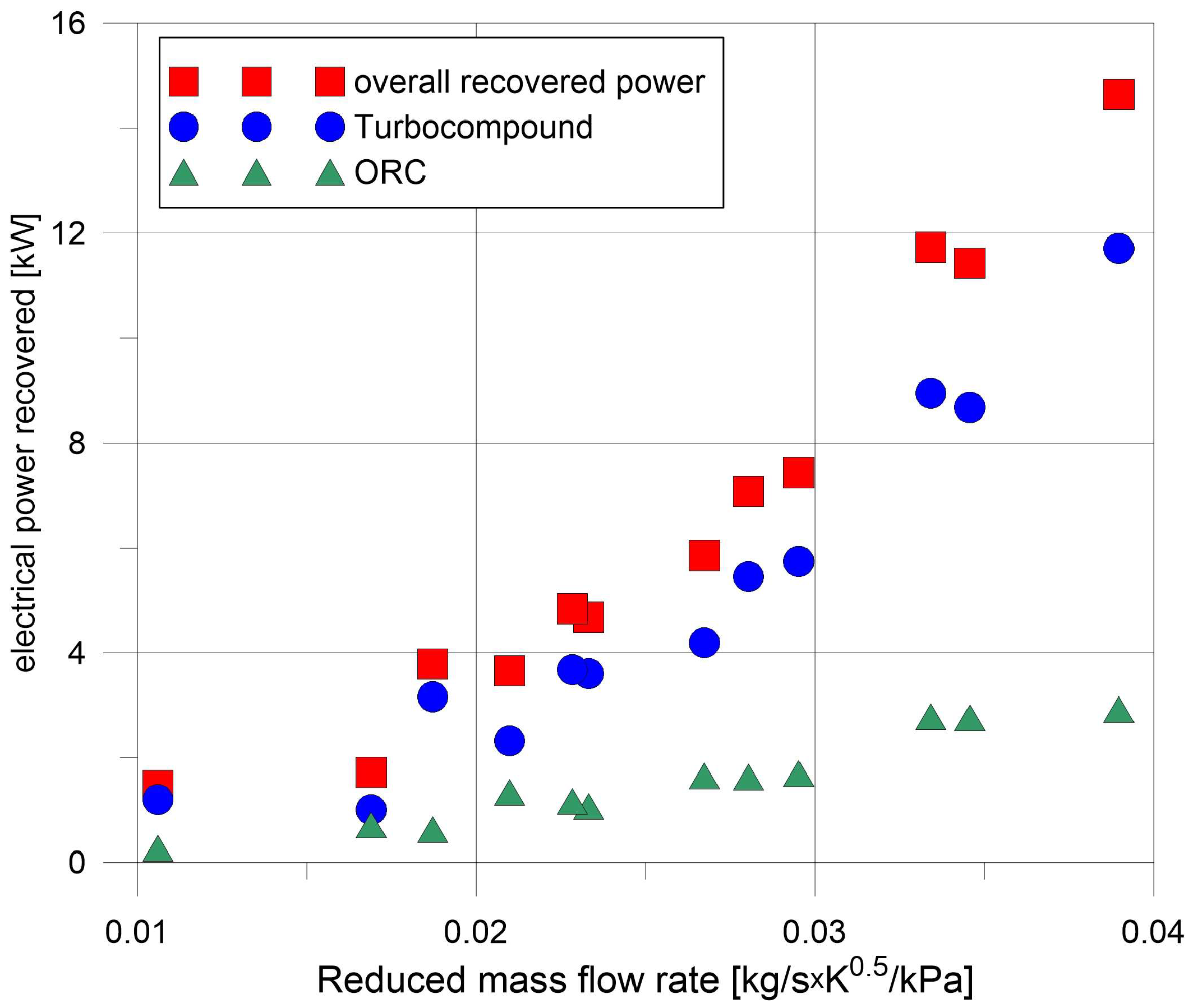
The total recovered power is above 14 kW at maximum engine power. Figure 15 reports the overall power recovered as a function of the reduced mass flow rate, which is a parameter that considers all the quantities of exhaust at the same time (i.e., mass flow rate, temperature, and pressure). The turbocompound electrical power recovered ranges from 1 to 12 kW, increasing almost linearly with the reduced mass flow rate of exhaust gases. On the other hand, up to 3 kW of ORC net electrical power is recovered. The graph demonstrates that the ORC accounts for about 20–25% of the overall power recovered, highlighting the possible fundamental role of the turbocompound in the dual-stage recovery.
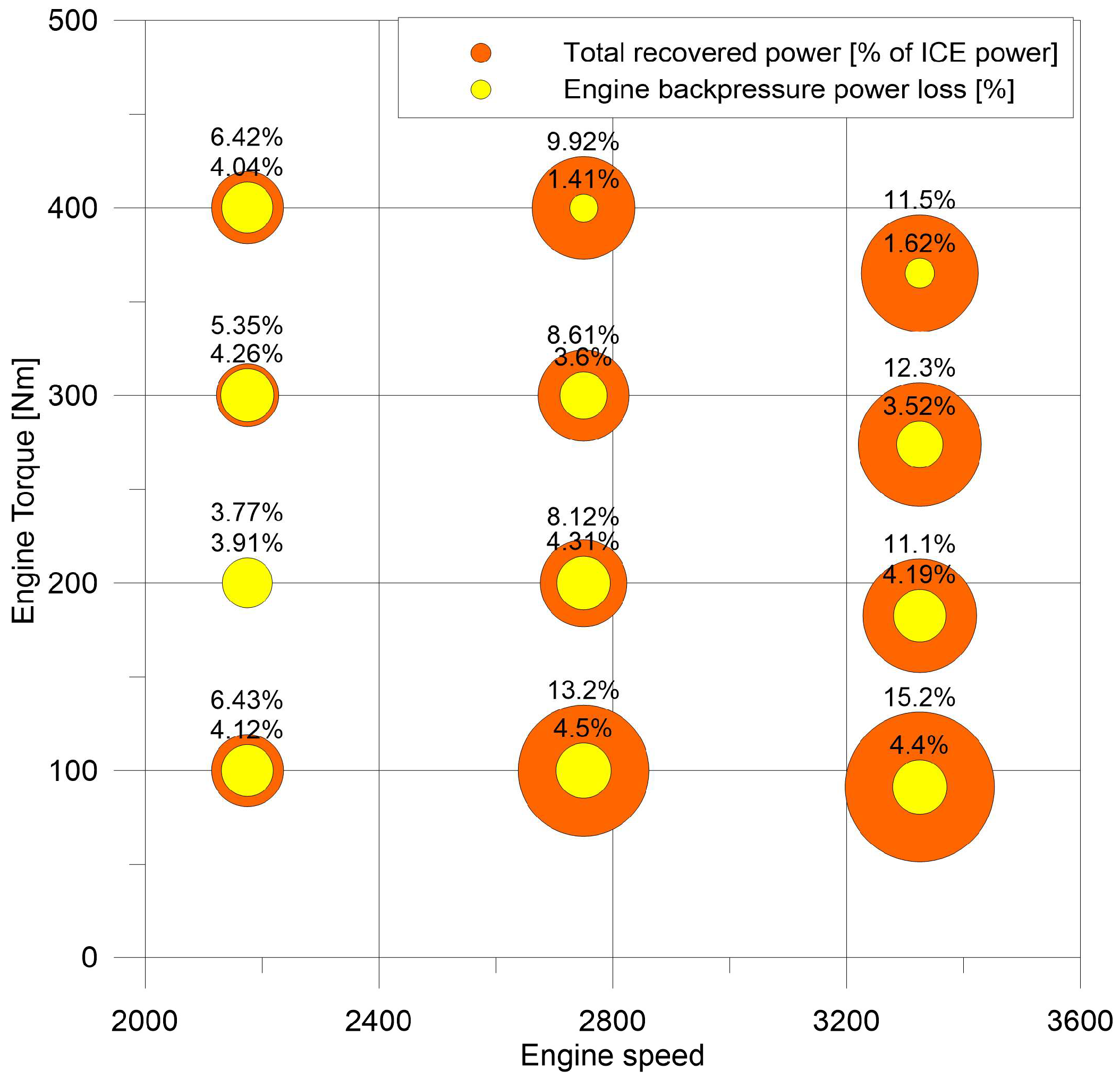
Figure 16 shows the percentage of total energy recovered from the engine power compared to the power loss introduced by the backpressure’s effect on the engine itself, as calculated through the map-based model of Figure 5. For almost all the working regions considered, the recovered power (orange circles in Figure 16) is higher than the power loss in relation to the backpressure (yellow circle). The gross overall energy recovery, without considering the backpressure effect, is on average equal to 9–10% in the operating region of the engine. The backpressure effect accounts for about 3–4% in most of the engine working points. The average net power recovery can be estimated to be 5–6%, with a peak of 10% in the working points with the highest revolution speed. Similar figures apply for carbon dioxide emission: considering that an average value of 224 gCO2/kWh can be considered for the reference engine, a mean value of 11–12 gCO2/kWh saved can be stated.
The engine loss does not consider the possible energy reduction related to the electrification of auxiliaries (engine cooling pump, lubrication oil pump, cabin conditioning, etc.), which are mechanically linked to the engine, taking power from it. These auxiliaries, in the progressive electrification of the powertrain, can be electrically driven by the recovered electrical energy from the turbocompound and ORC unit. In this way, the specific fuel consumption reduction shown in Figure 16 is underestimated.

4. Conclusions

The transportation sector is undergoing an intense technological evolution focused on decarbonization, as is happening for all other sectors that make use of fossil fuels. However, the path to be followed is more complex than that in other sectors. In fact, in order for different solutions to be feasible, they must align with all the other dimensions of sustainable development, such as the social dimension, considering that the ICE production sector is prevalent in many other economic sectors. Waste heat recovery, in light- and heavy-duty engines, is one of the most investigated solutions, since it can be easily implemented on board without significant changes in the powertrain while also ensuring effective increases in efficiency and paving the way to the increased electrification and hybridization of the vehicle system. It also requires components that reinforce existing production chains, giving support to the important thermomechanical sector.
The integration of a dual-stage waste heat recovery system, comprising a turbocompound and a bottomed organic Rankine cycle (ORC), has been proposed and studied using a model-based approach that considers experimental data for validation and boundary conditions, demonstrating significant and realistic potential for improving the efficiency of internal combustion engines. This study highlights the ability of the turbocompound to achieve high potential recovery over different engine exhaust boundary conditions (mass flow rate, temperature, and pressure). The increase in backpressure produced by the additional turbine is not negligible. For this reason, its effects on the pumping losses and the increase in specific fuel consumption produced in the engine have been estimated. The ORC-based unit, bottomed to the turbocompound, downstream in the exhaust line, can further increase the energy recovered, maintaining the gases at high temperatures and, thus, enthalpy, also after crossing the additional recovery turbine. Both energies recovered are considered in electrical form to maximize its exploitation after the battery storage section, while also considering conventional hybridized powertrains. This also opens the door to wider electrification, for instance, in auxiliary and ancillary components, reducing once more the energy needed for the powertrain.
In the engine working points considered, which cover a wide operating region of the engine itself, the recovered turbocompound electrical power ranges from 1 kW to 12 kW, while the ORC electrical net power is up to 3 kW, with a total recovered power that is above 14 kW in the highest conditions. The gross overall power recovered can be estimated to be about at 9% of the power of the turbocharged diesel engine used as a reference, in its operating region (torque vs. speed). The turbocompound recovers a substantial portion of the energy, contributing up to 75–80% of the total power recovered. Despite the backpressure effects, which increase the engine power by 3–4% in most operating points, the overall system achieves a net energy recovery of 5–6% in the engine power output. Similar figures apply to the carbon dioxide emissions prevented, and an average saving of 11–12 gCO2/kWh has been estimated in the engine working region considered. This is also a very significant value from an economic point of view, since each gram exceeding the international target represents a penalty for the vehicle manufacturers. The cost of the dual-stage system, on the other hand, would not be excessive, since the additional turbine is of the same technology of a conventional turbocharger, and the ORC components (heat exchangers, machineries, fluids, and piping) can be easily derived from other sectors (e.g., refrigeration and cabin air conditioning). Therefore, the cost/benefit ratio, including the cost avoided for the CO2 saved, will be positive.
An integrated control strategy that optimizes in a holistic way the efficiency of the engine, including backpressure reduction and the power recoverable from the dual-stage system, could also further increase recovery in a wider operating region. These findings underline the feasibility of adopting such advanced recovery mechanisms to enhance fuel efficiency and reduce greenhouse gas emissions, offering a promising pathway toward more sustainable transportation technologies during this ecological transition era.

Author Contributions

Conceptualization, R.C. and D.D.B.; methodology, D.D.B. and F.F.; software, F.D.P., D.D.B. and F.F.; validation, G.D.G. and R.C.; formal analysis, D.D.B. and G.D.G.; investigation, F.D.P. and G.D.G.; resources, R.C. and D.D.B.; data curation, D.D.B., F.D.P., F.F. and G.D.G.; writing—original draft preparation, D.D.B. and G.D.G.; writing—review and editing, R.C. and F.F.; visualization, D.D.B. and F.F.; supervision, R.C.; project administration, R.C. and D.D.B.; funding acquisition, R.C. All authors have read and agreed to the published version of the manuscript.

Funding

This research received no external funding.

Data Availability Statement

Dataset available on request from the authors.

Acknowledgments

The present work was developed in the framework of the National Relevant Interest Project PRIN “H2-ICE-Development of a hydrogen fuelled hybrid powertrain for urban buses”. AVL is acknowledged for the software used to retrieve experimental engine test bench data.

Conflicts of Interest

The authors declare no conflicts of interest.

Nomenclature

Acronyms
DHRDirect heat recovery
HDVHeavy-duty vehicle
HRVGHeat recovery vapor generator
IBCInverted Brayton cycle
ICEInternal combustion engine
IHRIndirect heat recovery
ORCOrganic Rankine cycle
SFCSpecific fuel consumption
TauxAuxiliary turbine
TCTurbocompound
WHRWaste heat recovery
Symbols
PPower
cpSpecific heat at constant pressure
hEnthalpy
mMass flow rate
pPressure
QrecRecovered thermal power
TTemperature
βPressure ratio
ηEfficiency
Subscripts
adAdiabatic
elElectric
exhExhaust
expExpander
uUseful
wfOrganic working fluid

References

  1. Crippa, M.; Guizzardi, D.; Pagani, F.; Banja, M.; Muntean, M.; Schaaf, E.; Monforti-Ferrario, F.; Becker, W.E.; Quadrelli, R.; Risquez Martin, A.; et al. GHG Emissions of All World Countries; Publications Office of the European Union: Luxembourg, 2024. [Google Scholar] [CrossRef]
  2. U.S. Energy Information Administration. International Energy Outlook 2023. Available online: https://www.eia.gov/outlooks/ieo/ (accessed on 28 November 2024).
  3. IEA. Road Transport; IEA: Paris, France, 2023; Available online: https://www.iea.org/reports/road-transport (accessed on 15 December 2024).
  4. Dornoff, J. CO2 Emission Standards for New Passenger Cars and Vans in the European Union; International Council on Clean Transportation: Washington, DC, USA, 2023; Available online: https://theicct.org/publication/eu-co2-standards-cars-vans-may23/ (accessed on 30 November 2024).
  5. ACEA. Fact Sheet: CO2 Standards for Heavy-Duty Vehicles. February 2023. Available online: https://www.acea.auto/fact/fact-sheet-co2-standards-for-heavy-duty-vehicles/ (accessed on 30 November 2024).
  6. Mulholland, E.; Rodriguez, F. The Revised CO2 Standards for Heavy-Duty Vehicles in the European Union; International Council on Clean Transportation: Washington, DC, USA, 2024; Available online: https://theicct.org/publication/revised-co2-standards-hdvs-eu-may24/ (accessed on 30 November 2024).
  7. Berube, M. Director, Vehicle Technologies Office. Vehicle Technologies Office Overview. In Proceedings of the 2017 Annual Merit Review and Peer Evaluation Meeting, Washington, DC, USA, 5–9 June 2017. [Google Scholar]
  8. Winkelmann, J.; Spinler, S.; Neukirchen, T. Green transport fleet renewal using approximate dynamic programming: A case study in German heavy-duty road transportation. Transp. Res. Part E Logist. Transp. Rev. 2024, 186, 103547. [Google Scholar] [CrossRef]
  9. Geng, P.; Cao, E.; Tan, Q.; Wei, L. Effects of alternative fuels on the combustion characteristics and emission products from diesel engines: A review. Renew. Sustain. Energy Rev. 2017, 71, 523–534. [Google Scholar] [CrossRef]
  10. Guido, C.; Beatrice, C.; Di Iorio, S.; Fraioli, V.; Di Blasio, G.; Vassallo, A.; Ciaravino, C. Alternative Diesel Fuels Effects on Combustion and Emissions of an Euro5 Automotive Diesel Engine. SAE Int. J. Fuels Lubr. 2010, 3, 107–132. [Google Scholar] [CrossRef]
  11. Di Blasio, G.; Ianniello, R.; Beatrice, C. Hydrotreated vegetable oil as enabler for high-efficient and ultra-low emission vehicles in the view of 2030 targets. Fuel 2022, 310, 122206. [Google Scholar] [CrossRef]
  12. Wouters, C.; Burkardt, P.; Steeger, F.; Fleischmann, M.; Pischinger, S. Comprehensive assessment of methanol as an alternative fuel for spark-ignition engines. Fuel 2023, 340, 127627. [Google Scholar] [CrossRef]
  13. Villforth, J.; Casal, K.A.; Rossi, E.; Vacca, A.; Cupo, F.; Chiodi, M.; Bargende, M. Experimental and Numerical Identification and Optimization of eFuel Potentials on Combustion Behavior and Engine Efficiency. Tongji Daxue Xuebao/J. Tongji Univ. 2021, 49, 83–95. [Google Scholar] [CrossRef]
  14. Bicer, Y.; Dincer, I. Life cycle environmental impact assessments and comparisons of alternative fuels for clean vehicles. Resour. Conserv. Recycl. 2018, 132, 141–157. [Google Scholar] [CrossRef]
  15. Oktar, H.E.; Tonyali, I.H.; Apaydin, A.H. A cost-effective and sustainable path to a green future: Retrofitting internal combustion engines for hydrogen fuel utilization. Int. J. Hydrogen Energy, 2024; in press. [Google Scholar] [CrossRef]
  16. Pramuanjaroenkij, A.; Kakaç, S. The fuel cell electric vehicles: The highlight review. Int. J. Hydrogen Energy 2023, 48, 9401–9425. [Google Scholar] [CrossRef]
  17. Razali, H.; Sopian, K.; Mat, A.S. Hydrogen as an alternative: Life cycle cost analysis between hydrogen internal combustion engine (Al+Hci) and gasoline engine based on brake specific fuel consumption. Appl. Mech. Mater. 2013, 315, 423–427. [Google Scholar] [CrossRef]
  18. Lehmann, J.; Winkenbach, M. Technology and energy choices for fleet asset decarbonization under cost uncertainty. Transp. Res. Part D Transp. Environ. 2025, 139, 104525. [Google Scholar] [CrossRef]
  19. .Singh, D.V.; Pedersen, E. A review of waste heat recovery technologies for maritime applications. Energy Convers. Manag. 2016, 111, 315–328. [Google Scholar] [CrossRef]
  20. SUPERTRUCK 2: Empowering Future Trucking; North American Council for Freight Efficiency (NACFE): Fort Wayne, IN, USA, 2024.
  21. Feng, D.J.; Tang, Y.; Zhu, S.; Deng, K.; Bai, S.; Li, S. Design of a combined organic Rankine cycle and turbo-compounding system recovering multigrade waste heat from a marine two-stroke engine. Energy 2024, 309, 133151. [Google Scholar] [CrossRef]
  22. Pasini, G.; Lutzemberger, G.; Frigo, S.; Marelli, S.; Ceraolo, M.; Gentili, R.; Capobianco, M. Evaluation of an electric turbo compound system for SI engines: A numerical approach. Appl. Energy 2016, 162, 527–540. [Google Scholar] [CrossRef]
  23. Fisher, R.; Ciappi, L.; Niknam, P.; Braimakis, K.; Karellas, S.; Frazzica, A.; Sciacovelli, A. Innovative waste heat valorisation technologies for zero-carbon ships—A review. Appl. Therm. Eng. 2024, 253, 123740. [Google Scholar] [CrossRef]
  24. Fu, J.; Liu, J.; Wang, Y.; Deng, B.; Yang, Y.; Feng, R.; Yang, J. A comparative study on various turbocharging approaches based on IC engine exhaust gas energy recovery. Appl. Energy 2014, 113, 248–257. [Google Scholar] [CrossRef]
  25. Jääskeläinen, H.; Majewski, W.A. Waste Heat Recovery for Heavy-Duty Diesel Engines: A Review of Mechanical Turbocompounding. In Proceedings of the ASME 2017 Internal Combustion Engine Division Fall Technical Conference, Seattle, WA, USA, 15–18 October 2017; Volume 1: Large Bore Engines, p. V001T01A012. [Google Scholar] [CrossRef]
  26. Teo Sheng Jye, A.; Pesiridis, A.; Rajoo, S. Effects of Mechanical Turbo Compounding on a Turbocharged Diesel Engine; SAE Technical Paper 2013-01-0103; SAE: Warrendale, PA, USA, 2013. [Google Scholar] [CrossRef]
  27. Katsanos, C.O.; Hountalas, D.T.; Zannis, T.C. Simulation of a heavy-duty diesel engine with electrical turbocompounding system using operating charts for turbocharger components and power turbine. Energy Convers. Manag. 2013, 76, 712–724. [Google Scholar] [CrossRef]
  28. Leng, L.; Cheng, J.; Shi, L.; Deng, K. Thermodynamic analysis on the effect of altitude on the exhaust energy recovery of electric turbocompound engines. Proc. Inst. Mech. Eng. Part D J. Automob. Eng. 2024. [Google Scholar] [CrossRef]
  29. Di Battista, D.; Di Bartolomeo, M.; Di Prospero, F.; Di Diomede, D.; Carapellucci, R.; Cipollone, R. Turbocompound energy recovery option on a turbocharged diesel engine. J. Phys. Conf. Ser. 2023, 2648, 012078. [Google Scholar] [CrossRef]
  30. Aghaali, H.; Ångström, H.-E. A review of turbocompounding as a waste heat recovery system for internal combustion engines. Renew. Sustain. Energy Rev. 2015, 49, 813–824. [Google Scholar] [CrossRef]
  31. Hountalas, D.; Katsanos, C.; Lamaris, V. Recovering Energy from the Diesel Engine Exhaust Using Mechanical and Electrical Turbocompounding; SAE Technical Paper 2007-01-1563; SAE: Warrendale, PA, USA, 2007. [Google Scholar] [CrossRef]
  32. Leng, L.; Ma, Z.; Cheng, J.; Shi, L.; Deng, K. Research on exhaust energy distribution regulation for fuel economy improvement of turbocompound diesel engine. Appl. Therm. Eng. 2023, 220, 119708. [Google Scholar] [CrossRef]
  33. Brancaleoni, P.P.; Corti, E.; Ravaglioli, V.; Moro, D.; Silvagni, G. Innovative torque-based control strategy for hydrogen internal combustion engine. Int. J. Hydrogen Energy 2024, 73, 203–220. [Google Scholar] [CrossRef]
  34. Di Battista, D.; Carapellucci, R.; Cipollone, R. Integrated evaluation of Inverted Brayton cycle recovery unit bottomed to a turbocharged diesel engine. Appl. Therm. Eng. 2020, 175, 115353. [Google Scholar] [CrossRef]
  35. Chagnon-Lessard, N.; Copeland, C.; Mathieu-Potvin, F.; Gosselin, L. Maximizing specific work output extracted from engine exhaust with novel inverted Brayton cycles over a large range of operating conditions. Energy 2020, 191, 116350. [Google Scholar] [CrossRef]
  36. Karabacak, M.; Turan, O. Off-design analysis of the inverted Brayton cycle engine. Aircr. Eng. Aerosp. Technol. 2024, 96, 954–963. [Google Scholar] [CrossRef]
  37. Butrymowicz, D.; Gagan, J.; Łukaszuk, M.; Śmierciew, K.; Pawluczuk, A.; Zieliński, T.; Kędzierski, M. Experimental validation of new approach for waste heat recovery from combustion engine for cooling and heating demands from combustion engine for maritime applications. J. Clean. Prod. 2021, 290, 125206. [Google Scholar] [CrossRef]
  38. de Araújo, L.R.; Morawski, A.P.; Barone, M.A.; Rocha, H.R.O.; Donatelli, J.L.M.; Santos, J.J.C.S. Response surface methods based in artificial intelligence for superstructure thermoeconomic optimization of waste heat recovery systems in a large internal combustion engine. Energy Convers. Manag. 2022, 271, 116275. [Google Scholar] [CrossRef]
  39. Novotny, V.; Spale, J.; Szucs, D.J.; Tsai, H.-Y.; Kolovratnik, M. Direct integration of an organic Rankine cycle into an internal combustion engine cooling system for comprehensive and simplified waste heat recovery. Energy Rep. 2022, 254, 124268. [Google Scholar] [CrossRef]
  40. Ping, X.; Yang, F.; Zhang, H.; Xing, C.; Yao, B.; Wang, Y. An outlier removal and feature dimensionality reduction framework with unsupervised learning and information theory intervention for organic Rankine cycle (ORC). Energy 2022, 254, 124268. [Google Scholar] [CrossRef]
  41. Pili, R.; Wieland, C.; Spliethoff, H.; Haglind, F. Numerical analysis of feedforward concepts for advanced control of organic Rankine cycle systems on heavy-duty vehicles. J. Clean. Prod. 2022, 351, 131470. [Google Scholar] [CrossRef]
  42. Sprouse, C.E., III. Review of Organic Rankine Cycles for Internal Combustion Engine Waste Heat Recovery: Latest Decade in Review. Sustainability 2024, 16, 1924. [Google Scholar] [CrossRef]
  43. Carapellucci, R.; Di Battista, D. Combined Supercritical CO2 Brayton Cycle and Organic Rankine Cycle for Exhaust Heat Recovery. ASME J. Energy Resour. Technol. 2024, 146, 062101. [Google Scholar] [CrossRef]
  44. Pan, M.; Zhu, Y.; Bian, X.; Liang, Y.; Lu, F.; Ban, Z. Theoretical analysis and comparison on supercritical CO2 based combined cycles for waste heat recovery of engine. Energy Convers. Manag. 2020, 219, 113049. [Google Scholar] [CrossRef]
  45. Fatigati, F.; Di Bartolomeo, M.; Di Battista, D.; Cipollone, R. A dual-intake-port technology as a design option for a Sliding Vane Rotary Expander of small-scale ORC-based power units. Energy Convers. Manag. 2020, 209, 112646. [Google Scholar] [CrossRef]
  46. Galindo, J.; Ruiz, S.; Dolz, V.; Royo-Pascual, L.; Haller, R.; Nicolas, B.; Glavatskaya, Y. Experimental and thermodynamic analysis of a bottoming Organic Rankine Cycle (ORC) of gasoline engine using swash-plate expander. Energy Convers. Manag. 2015, 103, 519–532. [Google Scholar] [CrossRef]
  47. Alshammari, F.; Karvountzis-Kontakiotis, A.; Pesyridis, A.; Usman, M. Expander Technologies for Automotive Engine Organic Rankine Cycle Applications. Energies 2018, 11, 1905. [Google Scholar] [CrossRef]
  48. Di Battista, D.; Cipollone, R. Experimental Analysis of an Organic Rankine Cycle Plant Bottoming a Heavy-Duty Engine Using Axial Turbine as Prime Mover. SAE Int. J. Engines 2017, 10, 1385–1397. [Google Scholar] [CrossRef]
  49. Di Battista, D.; Di Bartolomeo, M.; Villante, C.; Cipollone, R. A Model Approach to the Sizing of an ORC Unit for WHR in Transportation Sector. Commer. Veh. 2017, 10, 608–617. [Google Scholar] [CrossRef]
  50. Fatigati, F.; Di Battista, D.; Carapellucci, R. Model-based assessment of a feedforward-feedback control strategy for ORC-based unit in waste heat recovery application. Appl. Therm. Eng. 2025, 258, 124774. [Google Scholar] [CrossRef]
  51. Rosset, K.; Pajot, O.; Schiffmann, J. Experimental Investigation of a Small-Scale Organic Rankine cycle Turbo-Generator Supported on Gas-Lubricated Bearings. J. Eng. Gas Turbines Power 2021, 143, 051015. [Google Scholar] [CrossRef]
  52. T Gamma—Gamma Technologies Inc. GT-SUITE-Flow Theory Manual; Gamma Technologies: Westmont, IL, USA, 2020. [Google Scholar]
  53. Fatigati, F.; Coletta, A.; Di Bartolomeo, M.; Cipollone, R. The dynamic behaviour of ORC-based power units fed by exhaust gases of internal combustion engines in mobile applications. Appl. Therm. Eng. 2024, 240, 122215. [Google Scholar] [CrossRef]
  54. Lemmon, E.W.; Huber, M.L.; McLinden, M.O. REFPROP, NIST Standard Reference Database 23, version 8.0. Natl Std. Ref. Data Series (NIST NSRDS). National Institute of Standards and Technology: Gaithersburg, MD, USA, 2007.
  55. Fatigati, F.; Di Bartolomeo, M.; Di Battista, D.; Cipollone, R. Model based control of the inlet pressure of a sliding vane rotary expander operating in an ORC-based power unit. Appl. Therm. Eng. 2021, 193, 117032. [Google Scholar] [CrossRef]
  56. Fatigati, F.; Di Bartolomeo, M.; Di Battista, D.; Cipollone, R. Experimental characterization of a hermetic scroll expander operating in an ORC-based power unit bottoming an internal combustion engine. AIP Conf. Proc. 2019, 2191, 020069. [Google Scholar] [CrossRef]
  57. Fatigati, F.; Di Battista, D.; Cipollone, R. Permeability effects assessment on recovery performances of small-scale ORC plant. Appl. Therm. Eng. 2021, 196, 117331. [Google Scholar] [CrossRef]
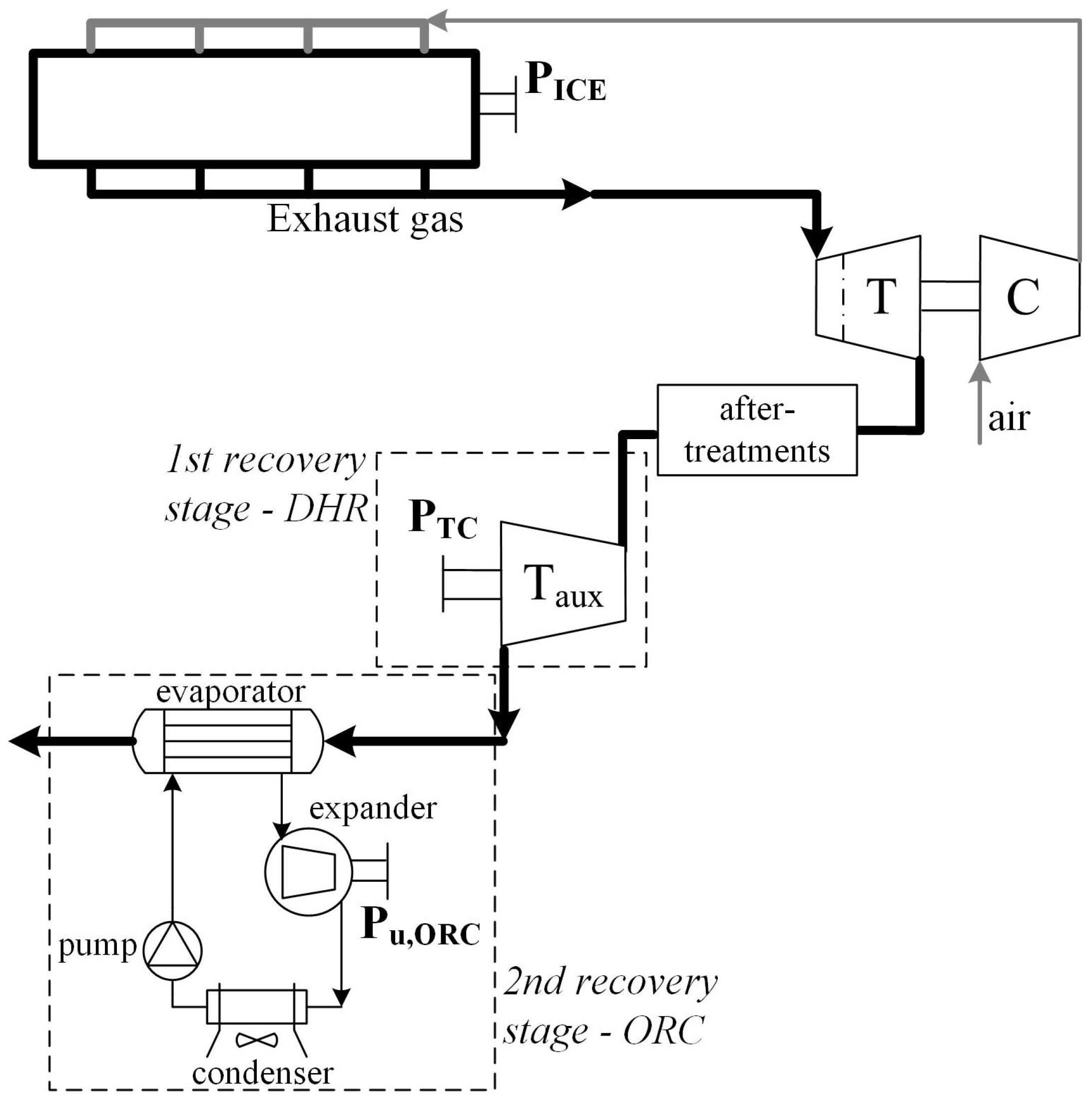
Figure 1. Layout of the recovery system proposed.
Energies 18 00623 g001
Figure 2. Flow diagram of the model developed.
Energies 18 00623 g002
Figure 3. Characteristic map of the auxiliary turbine considered for the direct heat recovery stage.
Energies 18 00623 g003
Figure 4. Electromechanical efficiency of the electric generator coupled to the turbocompound [51].
Energies 18 00623 g004
Figure 5. Backpressure effect map: percentage engine power loss in relation to the increase in the backpressure produced and engine exhaust pressure (downstream of the turbocharger–turbocompound inlet section).
Energies 18 00623 g005
Figure 6. An example of an entropic diagram of an ORC with hot and cold sources, highlighting the minimum and maximum operating pressures of the ORC unit. Dashed line is the saturation curve of the organic fluid (R245fa).
Energies 18 00623 g006
Figure 7. Evaporating pressure of the ORC unit and mass flow rate of the organic fluid implemented in the model.
Energies 18 00623 g007
Figure 8. Relationship between the organic fluid mass flow rate and the heat recovered, Qrec, from the ICE’s exhaust gases.
Energies 18 00623 g008
Figure 9. Resulting ORC thermodynamic cycle efficiency as a function of the inlet temperature and the mass flow rate of the exhaust gases in the evaporator.
Energies 18 00623 g009
Figure 10. Final electrical power recovered from the direct heat recovery stage (TC: turbocompound).
Energies 18 00623 g010
Figure 11. Increase in backpressure produced by the auxiliary turbine (turbocompound) in the engine exhaust line.
Energies 18 00623 g011
Figure 12. Temperature of the exhaust gas downstream of the turbocompound; this heat is then available for the second (indirect) heat recovery stage.
Energies 18 00623 g012
Figure 13. Heat recovered by the ORC unit as a function of the temperature and mass flow rate of exhaust gases entering the evaporator.
Energies 18 00623 g013
Figure 14. Final net ORC electrical power as a function of temperature and mass flow rate of exhaust gases entering the evaporator.
Energies 18 00623 g014
Figure 15. Resulting electrical power recovered from the dual-stage recovery system and breakdown with the turbocompound and bottomed ORC sections. Reduced mass flow rate is calculated in turbocompound inlet conditions.
Energies 18 00623 g015
Figure 16. Comparison on the engine map of the total electric power recovered and estimated engine power losses in relation to the backpressure increase (F1C 3.0 l turbocharged diesel engine).
Energies 18 00623 g016
Table 1. Engine working points considered for assessing dual-stage energy recovery.
Engine SpeedEngine TorqueEngine PowermexhTexhpexh
RPMNmkWg/s°Cbar
2175400.291.2122.9501.91.279
2175200.145.669.8480.01.134
2175300.1568.492.1519.71.235
2175100.0522.849.3350.81.161
275020057.6114.0432.61.299
275030086.4138.1493.31.295
2750400115.2157.5553.21.310
275010028.893.9380.31.281
3325365.2127.2181.8619.71.394
332591.331.8116.9442.11.369
3325273.995.4159.9548.81.372
3325182.663.6136.0485.81.336
Disclaimer/Publisher’s Note: The statements, opinions and data contained in all publications are solely those of the individual author(s) and contributor(s) and not of MDPI and/or the editor(s). MDPI and/or the editor(s) disclaim responsibility for any injury to people or property resulting from any ideas, methods, instructions or products referred to in the content.