Abstract
In grid-connected inverter systems, grid-connected filters can effectively eliminate harmonics. High-order filters perform better than conventional filters in eliminating harmonics and can reduce costs. For high-order filters, the use of multi-objective optimization algorithms for parameter optimization presupposes that the circuit structure must be known. To realize the design of the filter structure and related circuit parameters that meet the requirements of the grid-connected inverter system during the design process, this paper proposes a reinforcement learning (RL) method for designing higher-order filters. Our approach combines key domain knowledge with the characteristics of structural changes to obtain some constraints, which are then processed to obtain reward and are incorporated into RL strategy learning to determine the optimal structure and corresponding circuit parameters. The proposed method realizes the simultaneous design of parameters and structures in filter design, which greatly improves the efficiency of filter design. Simulation results for the corresponding grid-connected system setup show that the grid-connected filter designed by our method demonstrates a good performance in terms of filter dimension, harmonic rejection, and total harmonic distortion.
1. Introduction
Grid-connected inverters are crucial in sustainable energy generation systems [1]. However, the use of pulse width modulation (PWM) injects a large amount of harmonics into the grid-connected inverter system [2]. Therefore, it is usually necessary to insert a passive low-pass filter between the inverter and the grid to eliminate the effect of higher harmonics on the system [3].
Specifically, LCL-type filters are widely used because of their excellent high-frequency attenuation performance and the simplicity of their design method [4,5]. However, such filters usually require larger inductors, which not only leads to higher costs, but also causes larger voltage drops [6].
Recently, to obtain higher harmonic attenuation and lower inductor cost, LC series resonant branches have been widely used in the design of grid-connected filters [7]. The LLCL filter circuit contains a series resonant branch [8], which particularly attenuates the current ripple component at the switching frequency and lowers the total inductance. However, its attenuation in the high frequency band is only −20 dB/decade. Topological derivation of filters up to the fifth order reveals that the addition of LC resonant branches to the LCL filter provides better harmonic rejection [9]. The LCL filter attenuates at −40 dB/decade in the high-frequency band. Hence, higher-order grid-connected filters based on LCL and LC resonant branches are becoming popular. The LC resonant branch is also called a trap branch. The inductor–trap–capacitor–inductor (LTCL) filter can attenuate the current ripple components at the multiples of switching frequencies and guarantee −60 dB/decade attenuation in the high-frequency band [10]. The number of trap branches (n) of the LTCL filter is not fixed. To reduce the capacity of individual inductors, LTLCL filters are proposed based on the LTCL structure [11].
Filter parameter design is also an important aspect. Conventional methods are based on expert experience for dynamic tuning of parameters [12]. Expert design knowledge comes mainly from the constraints of some grid-connected standards and from trial-and-error experience. In other words, the parameter range is roughly determined according to the constraints of grid-connected current harmonics [13], current ripple [14], reactive power [15], etc., and then the parameters are tuned step by step. Based on the existing domain knowledge, some advanced methods are used to automate the parameter design. LCL parameter optimization methods based on particle swarm algorithm (PSO) and genetic algorithm (GA) are proposed in [16,17], respectively, where the designed objective functions include total inductance, total harmonic distortion (THD), etc. A clone-selection algorithm is used to optimize the parameters of the LCL filter [18]. Higher-order filter parameters such as LTLCL can also be obtained using a multi-objective optimization algorithm [11]. However, the parameter optimization for LTLCL presupposes that the topology must be known. In practice, optimization of the filter topology takes precedence over parameter optimization.
Artificial intelligence techniques are now widely used in the field of circuit design and power electronics topology design [19], and in particular, reinforcement learning (RL) is popular among designers. A step-by-step chip layout method is proposed based on reinforcement learning [20]. An analog circuit design method based on GCN-RL is proposed in [21]. In the field of power electronics, researchers have also used reinforcement learning to do topology derivation for DC–DC converters [22]. In summary, RL is flexible in the design process, so RL studies for circuits can also be used for filter structure and parameter optimization.
To further explore the potential of RL in high-order filter design, this paper focuses on the expandable LTLCL high-order filter, which also features a large search space due to its variable structure. The major contributions of this article are summarized as follows:
- The proposed method can simultaneously optimize the structure and parameters of the filter.
- By using RL, the proposed method can automatically design filters with certain specifications.
- By using the proposed method, the performances of the designed higher-order grid-connected filters are greatly improved.
The rest of this paper is organized as follows. The proposed learning architecture for filter design is presented in Section 2. Section 3 describes the specific characteristics and electrical design constraints of the LTLCL filter. In Section 4, the learning results are illustrated, and the highest-scoring filter circuit is verified by simulation and experimental results. Finally, Section 5 concludes the paper.
2. Learning Architecture
As shown in Figure 1, the proposed learning architecture is based on RL. In this framework, the design of grid-connected filters can be regarded as a step-by-step design process. The RL agent changes the circuit structure and parameters through actions based on the circuit state, and obtains the reward given by the evaluation program. The reward from changing the circuit is equal to 0 for all steps except the last one, which consists of various electrical constraints on the filter. Through multiple iterations, the agent improves the quality of its decisions and eventually learns the best strategy for maximizing the reward.

Figure 1.
Overview of our RL framework and the design process. (a) The RL framework. (b) An episode of the RL framework. The parameters of , , and are changing, so the final reward is (e.g., ).
In this paper, the LTLCL-type filter is the object of study, of which structure is as shown in Figure 2. The number of trap branches of LTLCL is equal to . Then, including fixed components, 2 + 4 components need to be determined for a complete filter design.
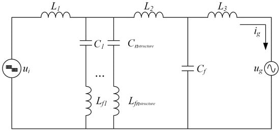
Figure 2.
The topology of the LTLCL filter.
In our learning framework, the action , state and reward are defined as follows:
- Action:
In this paper, the action consists of two parts. At the beginning of a complete filter design, a0 determines the number of trap branches, i.e., . Component parameters are determined by each subsequent step of the action at until a complete circuit is obtained. Before designing the filter, the lower and upper bounds [, ] for the parameter x will be approximately determined, followed by the utilization of a discrete action space to adjust the component parameters. Then, the equation for the variation of parameter x is defined as follows:
where is the step size of the parameter change, and takes values in the range [0, ].
- 2.
- State:
A complete circuit requires the determination of the number of trap branches and 2 + 4 component parameters. This means that the state will contain two parts, one part is a valid dimension for determining the circuit structure and parameters, and the other part is considered as an invalid dimension. Therefore, the dimension of the state should be set to a larger value .
Algorithm 1 is the key to the proposed RL-based LTLCL filter design. It initializes necessary variables like the highest score and buffers. In each episode, it gets the state, computes relevant values, updates the highest score if needed, and stores transitions. After all episodes in an epoch, it calculates the optimization target and uses ADAMW to update network parameters. Through iterative training across epochs, it enables the agent to learn the optimal filter design strategy considering electrical constraints and the reward mechanism.
| Algorithm 1. RL-based LTLCL filter design algorithm |
1: Initialize highest score 2: for i = 1 to M do 3: Initialize replay buffer and 4: for j = 1 to N do 5: Receive observation state 6: Compute for every step t 7: Compute for every step t and add to 8: if then 9: 10: end if 11: Store transition (; ; ) in 12: end if 13: for j = 1 to K do 14: Compute the optimization target: 15: 16: Update the parameters θ of the networks with by ADAMW 17: end for 18: end for |
- 3.
- Reward:
The reward is an important indicator used to measure the performance of the designed filter. The reward is always equal to 0 until the end of an episode. When the state is complete, it is then passed into the circuit evaluation program to obtain sc. The reward defined as follows:
where sc is the evaluation score. The specific electrical constraints and the construction of the reward can be seen in Equation (21).
In this paper, the Proximal Policy Optimization (PPO) [23] algorithm is employed for training the agent. PPO uses a surrogate objective function to optimize the policy network (Actor) and value function (Critic). The actor network represents the policy and outputs the probability of taking each action in a given state. The critic network estimates the value function and outputs the expected reward for a given state. PPO uses the actor to collect experience data from the environment. It then utilizes this experience to train both the actor and critic networks. The goal of PPO is to maximize the optimization target J defined as:
where , and are hyperparameters, represents the entropy regularization term of the policy distribution, and is the estimated advantage function defined as:
where and are hyperparameters, the policy is , is equal to , and is the accumulated discounted reward. represents the expected return, which is the long-term cumulative reward that the policy expects to obtain after taking an action in a certain state, and is the value estimate of the future state by the old Critic network.
The RL-based filter design algorithm is as shown in Algorithm 1. In each epoch, N times and are calculated, then the highest score is recorded along with the corresponding circuit. The algorithm then updates the network hyperparameters by computing the optimization objective using ADAMW [24].
3. LTLCL-Type Grid-Connected Filters and Electrical Constraints
3.1. LTLCL-Type Grid-Connected Filter
The LTLCL filter topology is as shown in Figure 2, where is the inverter-side inductor, is the splitting grid-side inductor, and is the gride-side inductor. The topology consists of parallel LC series resonant circuits, where the i-th branch involves the resonant capacitor and the resonant inductor .
LTLCL filter has better attenuation of higher harmonics. The LTLCL filter transfer function can be derived as:
Figure 3 shows the Bode diagrams of LTLCL with two trap branches ( = 2), where is the switching angular frequency. Since the resonant frequency of the trap branch is a multiplicative switching frequency, when Ci is determined, can be calculated by
Thus, the number of component parameters designed becomes + 4.
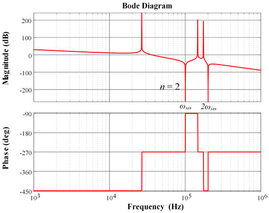
Figure 3.
Bode diagrams of the transfer function.
3.2. System Configuration
Figure 4 shows the three-phase grid-connected inverter. is the DC link voltage. In this paper, the sinusoidal PWM (SPWM) is used. The a-phase bridge output voltage can be calculated as:
where is the modulation ratio, is the modulation frequency, is the carrier frequency, and J is the Bessel function.
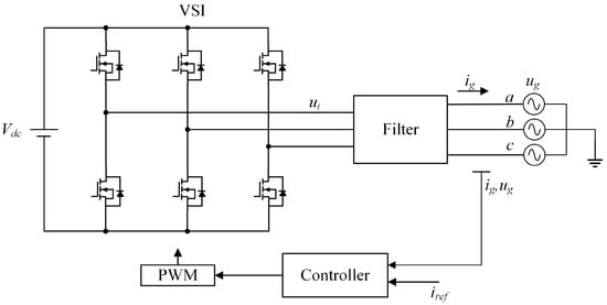
Figure 4.
Grid-connected inverter system.
For odd multiples (h = 1, 3, 5, …) of the carrier frequency harmonic nearby, = 0; for even multiples (h = 2, 4, 6, …) of the carrier switching frequency, = 0. Therefore, the harmonic components of the bridge arm output voltage only appear at frequencies where h + k is odd.
3.3. Electrical Constraints
- (1)
- The reactive power does not exceed 5% of the rated power, so the sum of capacitors is limited bywhere is the rated power. Based on the above inequality, the reward is constructed as follows:
- (2)
- The voltage drop across the total series inductors does not exceed 10% of the rated voltage rms. Therefore, the total series inductance value is limited byThe reward is constructed as follows:
- (3)
- The inverter-side inductance determines the maximum peak-to-peak current ripple. The choice has been made to enable support for ripple current of up to 60% of the rated current. The constraint is as follows:This constraint can be used to determine the lower and upper bounds of .
- (4)
- The designed filter consists of trap branches. The zero-impedance paths formed by the trap branches can effectively attenuate harmonic components at multiple switching frequencies. Therefore, it is necessary to ascertain whether the harmonic component at ( + 1) is within 0.3% of the fundamental current. As shown in (8), the harmonic amplitude of the output voltage can be calculated, as follows:In this paper, when + 1 is odd, the investigation is limited to harmonic amplitudes for k = ±2, ±4; when + 1 is even, consideration is restricted to harmonic amplitudes for k = ±1, ±3. Therefore, the maximized harmonic components around ( + 1) can be described as:The constraint can be derived as:where is the amplitude of the reference grid current. The reward is constructed as follows:denotes the reward when the constraint (16) is satisfied and is a constant. In this paper, equals 10.
- (5)
- To avoid system instability caused by harmonic resonance in the high-frequency band and low-frequency band of the filter, its characteristic resonant frequency needs to be limited between 10 and 0.5. With the same total capacitance, the first resonant frequency of the LTLCL filter is approximately the resonant frequency of the LCL filter. Therefore, the resonant frequency of the LCL filter can be used to approximate the first resonant frequency of the LTLCL filter. The first resonant frequency can be derived as:Hence, is constructed as follows:is also a constant larger than 0. In this paper, equals 10.
- (6)
- also includes a limit on the total capacitance, i.e., the smaller the total capacity, the higher the . In addition to the capacitance, the objective is to minimize the total inductance. Therefore, with respect to the total inductance, a penalty term can be constructed as follows:
- (7)
- To limit the order of the filter, a penalty term related to the order is therefore introduced. Let the coefficient be , which in this case equals 0.5. Then the reward is constructed as follows:
In summary, the total score sc obtained from the circuit evaluation program is derived as:
where are the weighting factors introduced to balance order of magnitude of .
4. Verification
The multi-objective optimization algorithm can be used to optimize the parameters of the grid-connected filter, as seen in some related studies. For instance, in the literature [25], they focused on optimizing the LCL filter using four metaheuristic algorithms, namely the Whale Optimization Algorithm, the Circle Search Algorithm, the Particle Swarm Optimization, and the Gray Wolf Optimization. Their approach aimed to minimize the total harmonic distortion (THD) and the error between the reference and real grid current, considering the LCL filter’s parameters, the damping coefficient of the capacitor current feedback active damping (CCF–AD) method, and the gains of the proportional resonant (PR) controller. However, the dimension of its decision vector varies with ; when changes, it must be re-optimized.
In our method, when the maximum value of is determined, the dimension of state does not change as changes, so only one exploration is needed. During the process, in addition to finding the highest-scoring filter, the highest-scoring circuit parameters are recorded for each of the four cases. This allows comparing not only the global optimal case but also the local optimal case.
The training program runs on a computer with AMD Ryzen 7 2700 CPU, Nvidia RTX2080 GPU, and 16 GB of RAM. The configurations of the parameters of the RL algorithm are as listed in Table 1.

Table 1.
Parameters of the RL algorithm.
In this validation, the maximum value of was set to 5. The approximate block diagram of the simulation is as shown in Figure 4. Simulation setting is as shown in Table 2. According to the simulation settings, the upper and lower limits of the inductor-capacitor can be obtained as shown in Table 3. The lower and upper bounds for parameters are determined based on grid-connected requirements. For LTLCL filter components, these bounds are set considering electrical constraints. Initial values are randomly chosen within this range for RL training start.

Table 2.
Simulation setting.

Table 3.
Upper and lower limits of component parameters.
4.1. Train Result
Figure 5 shows variation of reward (i.e., mean episode reward) and best score in training. Figure 5a shows that the reward converges after about 2 million steps. According to the designed constraints, the value of eventually converges to the case of = 4. According to Figure 5b, the best score also converges to a fixed value. The circuit structure and the waveform diagram of the grid current obtained from the simulation are shown in Figure 6.

Figure 5.
Reward and best score in training: (a) Trends in reward. The model search to the optimal structure and parameters takes about 7–8 min; (b) Trends in best score.
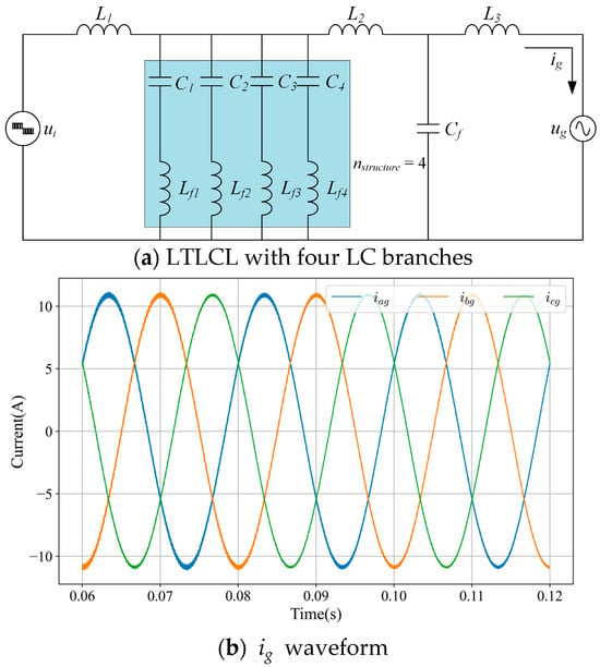
Figure 6.
Best filter structure and waveform.
To verify that the best case in the same evaluation system is , a separate search is conducted for the cases where ns , followed by the identification of the best-scoring circuits. The parameters of the grid-connected filter corresponding to the highest score and optimal parameters in other cases are shown in Table 4. To balance the quality of filtering and the cost of the circuit, the total capacity of inductors and capacitors should be set to a reasonable value. According to Table 4, The case of requires a smaller total inductance and total capacitance, which complies with the design objectives. According to constraint (9), the upper limit of the total capacitance is 5.48 µF, and the designed filters meet this constraint.

Table 4.
The filter parameters corresponding to the highest score.
Total harmonic distortion rate (THD) is an important indicator of grid-side current quality. Simulations are done for each of the four filters individually, recording the current and doing FFT analysis on them to calculate their THDs. By FFT analysis, it can be found that when , the THD is at minimum and the harmonic amplitudes are all less than 0.3% of the fundamental current amplitude. It can also be seen from Figure 7 that the higher the , the greater the attenuation of the current harmonics at the multiplicative switching frequency, but the trapped branch introduces positive resonance peaks, thus causing oscillations at some frequencies and thus increasing the THD. Since current harmonics are mainly concentrated at multiples of the switching frequencies, positive resonance points should be avoided near these frequencies as much as possible.
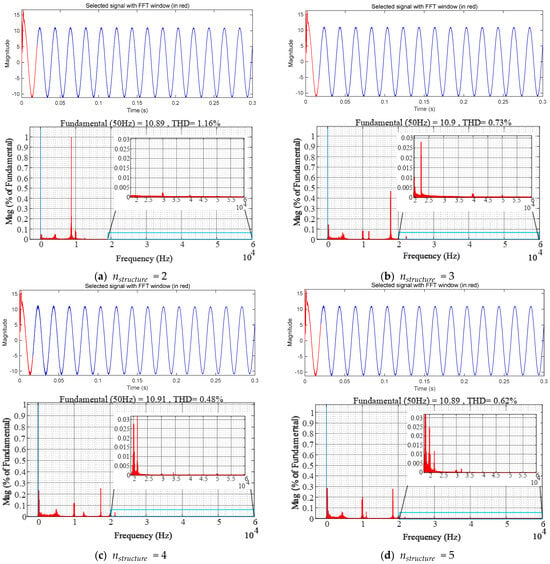
Figure 7.
FFT analysis for in different cases (a,b,d) are the grid current FFT analysis obtained by simulating the circuit obtained by doing parameter search for the fixed-structure circuit alone. (c) is the FFT analysis of the obtained from the optimal circuit simulation in the global optimization.
4.2. Solution Comparsion
To verify whether the filter parameters designed by RL are optimal, two multi-objective optimization algorithms, namely NSGA-II and SMS-EMOA, are selected for conducting parameter search in the case of . Subsequently, simulations are performed, and the results are compared. According to the Equations (6), (9), (11), (13), (16), and (18), the objective function and constraints are constructed as follows:
Equation (23) serves for computing the total inductance of the filter, whereas Equation (24) is dedicated to calculate the total capacitance. Equation (25) primarily functions to assess the attenuation level of the filter concerning harmonics at specific frequencies. Additionally, Equation (26) represents a comprehensive objective function that combines multiple factors, including total inductance, total capacitance, and harmonic attenuation, across various frequencies. Finally, Equation (27) constitutes a set of constraints designed to confine the value range of filter parameters, thereby guaranteeing the practical feasibility of the designed filter.
A multi-objective optimization algorithm is employed to acquire a set of feasible solutions, followed by the utilization of the scoring Equation (21) to identify the parameters with the highest scores. Figure 8 shows the feasible solutions and the final decision vectors for both algorithms (NSGA-II and SMS EMOA).
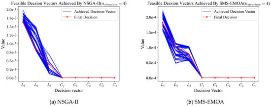
Figure 8.
The feasible non-dominated solutions obtained by NSGA–II and SMS–EMOA on LTLCL with four LC series resonant circuits, respectively.
In summary, the parameters of the filter designed by RL and the filter designed by the optimization algorithm are shown in Table 5. The filters obtained by NSGA-II and SMS EMOA algorithms are simulated, and FFT analysis of the grid current is performed as shown in Figure 9. By comparing Figure 7c, Figure 9a, and Figure 9b, it can be seen that the filter designed by RL has a smaller THD value. Combined with Table 5, although the filters designed by the multi-objective optimization algorithms have slight good filtering, its total capacity of inductor–capacitor is higher, which will increase the design cost.

Table 5.
Optimal parameters obtained by different methods.
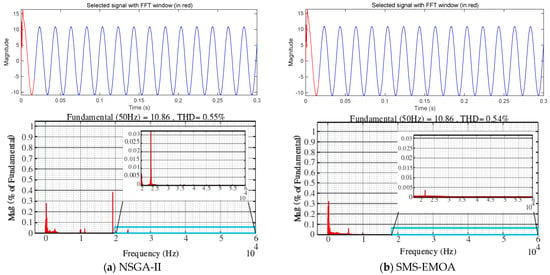
Figure 9.
FFT analysis.
Our proposed method allows not only to optimize the structure, i.e., the filter topology is not fixed, but also to optimize the component parameters. The reinforcement learning approach is more suitable for designing high-order grid-connected filters than the complexity of multi-objective optimization algorithm construction.
5. Conclusions
This paper presents a reinforcement learning approach for designing high-order filters, which can adapt to different application scenarios by varying the structure and parameters of the LTLCL filter. This approach is the first to achieve simultaneous optimization of filter topology and component values, and it can explore the optimal circuit from a global perspective.
For the proposed method, a comparison is made between the search results in the scenario of varying structure and those in the case of fixed structure. According to the simulation setup, the optimal structure obtained by our method is the case where the number of branches is four. The optimization results achieved by the multi-objective optimization algorithm in the case are compared. The filter designed by RL performs well in terms of filtering performance and cost reduction.
In the future, the proposed method can be used to design more complex filter circuits.
Author Contributions
Conceptualization, L.L., X.L., and J.Z.; Methodology, L.L., J.Z., and W.Y.; Software, W.Y.; Validation, X.L., J.Z., and W.Y.; Formal analysis, L.L. and M.D.; Investigation, L.L. and X.L.; Resources, L.L. and M.D.; Data curation, X.L. and J.Z.; Writing—original draft preparation, X.L. and W.Y.; Writing—review and editing, L.L., X.L., and J.Z.; Visualization, W.Y. and M.D.; Supervision, X.L. and J.Z.; Project administration, X.L. and J.Z.; Funding acquisition, L.L. and M.D. All authors have read and agreed to the published version of the manuscript.
Funding
This research received no external funding.
Data Availability Statement
The data presented in this study are available on request from the corresponding author due to privacy reasons.
Conflicts of Interest
The authors declare no conflicts of interest.
References
- Heydt, G.T. The Next Generation of Power Distribution Systems. IEEE Trans. Smart Grid 2010, 1, 225–235. [Google Scholar] [CrossRef]
- Erika, T.; Holmes, D.G. Grid current regulation of a three-phase voltage source inverter with an LCL input filter. IEEE Trans. Power Electron. 2003, 18, 888–895. [Google Scholar] [CrossRef]
- Islam, M.; Afrin, N.; Mekhilef, S. Efficient Single Phase Transformerless Inverter for Grid-Tied PVG System with Reactive Power Control. IEEE Trans. Sustain. Energy 2016, 7, 1205–1215. [Google Scholar] [CrossRef]
- Liserre, M.; Blaabjerg, F.; Hansen, S. Design and control of an LCL-filter-based three-phase active rectifier. IEEE Trans. Ind. Appl. 2005, 41, 1281–1291. [Google Scholar] [CrossRef]
- Wu, X.; Li, X.; Yuan, X.; Geng, Y. Grid Harmonics Suppression Scheme for LCL-Type Grid-Connected Inverters Based on Output Admittance Revision. IEEE Trans. Sustain. Energy 2015, 6, 411–421. [Google Scholar] [CrossRef]
- Poongothai, C.; Vasudevan, K. Design of LCL Filter for Grid-Interfaced PV System Based on Cost Minimization. IEEE Trans. Ind. Appl. 2019, 55, 584–592. [Google Scholar] [CrossRef]
- Wu, W.; He, Y.; Tang, T.; Blaabjerg, F. A New Design Method for the Passive Damped LCL and LLCL Filter-Based Single-Phase Grid-Tied Inverter. IEEE Trans. Ind. Electron. 2013, 60, 4339–4350. [Google Scholar] [CrossRef]
- Wu, W.; He, Y.; Blaabjerg, F. An LLCL Power Filter for Single-Phase Grid-Tied Inverter. IEEE Trans. Power Electron. 2012, 27, 782–789. [Google Scholar] [CrossRef]
- Xu, D.; Wang, F.; Ruan, Y.; Mao, H.; Zhang, W.; Yang, Y. Topology deduction and analysis of grid-interfacing filters. Diangong Jishu Xuebao/Trans. China Electrotech. Soc. 2015, 30, 15–25. [Google Scholar]
- Xu, J.; Yang, J.; Ye, J.; Zhang, Z.; Shen, A. An LTCL Filter for Three-Phase Grid-Connected Converters. IEEE Trans. Power Electron. 2014, 29, 4322–4338. [Google Scholar] [CrossRef]
- Zhang, Z.; He, C.; Ye, J.; Xu, J.; Pan, L. Switching ripple suppressor design of the grid-connected inverters: A perspective of many-objective optimization with constraints handling. Swarm Evol. Comput. 2019, 44, 293–303. [Google Scholar] [CrossRef]
- Solatialkaran, D.; Zare, F.; Saha, T.K.; Sharma, R. A Novel Approach in Filter Design for Grid-Connected Inverters Used in Renewable Energy Systems. IEEE Trans. Sustain. Energy 2020, 11, 154–164. [Google Scholar] [CrossRef]
- Wang, X.; Ruan, X.; Liu, S.; Tse, C.K. Full Feedforward of Grid Voltage for Grid-Connected Inverter with LCL Filter to Suppress Current Distortion Due to Grid Voltage Harmonics. IEEE Trans. Power Electron. 2010, 25, 3119–3127. [Google Scholar] [CrossRef]
- Jiao, Y.; Lee, F.C. LCL Filter Design and Inductor Current Ripple Analysis for a Three-Level NPC Grid Interface Converter. IEEE Trans. Power Electron. 2015, 30, 4659–4668. [Google Scholar] [CrossRef]
- Beres, R.N.; Wang, X.; Blaabjerg, F.; Liserre, M.; Bak, C.L. Optimal Design of High-Order Passive-Damped Filters for Grid-Connected Applications. IEEE Trans. Power Electron. 2016, 31, 2083–2098. [Google Scholar] [CrossRef]
- Cai, Y.; He, Y.; Zhou, H.; Liu, J. Design Method of LCL Filter for Grid-Connected Inverter Based on Particle Swarm Optimization and Screening Method. IEEE Trans. Power Electron. 2021, 36, 10097–10113. [Google Scholar] [CrossRef]
- Liserre, M.; Dell’Aquila, A.; Blaabjerg, F. Genetic algorithm-based design of the active damping for an LCL-filter three-phase active rectifier. IEEE Trans. Power Electron. 2004, 19, 76–86. [Google Scholar] [CrossRef]
- Cho, J.H.; Kim, D.-H.; Virikova, M.; Sinak, P. Design of LCL filter using hybrid intelligent optimization for photovoltaic system. In Ubiquitous Computing and Multimedia Applications—Second International Conference, UCMA 2011, Proceedings, 2011; Springer: Berlin/Heidelberg, Germany, 2011; pp. 90–97. [Google Scholar] [CrossRef]
- Yan, W.; Dong, M.; Li, L.; Liang, R.; Xu, C. Filter Design for Single-Phase Grid-Connected Inverter Based on Reinforcement Learning. In Proceedings of the 2022 IEEE 17th Conference on Industrial Electronics and Applications (ICIEA), Chengdu, China, 16–19 December 2022; pp. 261–266. [Google Scholar] [CrossRef]
- Mirhoseini, A.; Goldie, A.; Yazgan, M.; Jiang, J.W.; Songhori, E.; Wang, S.; Lee, Y.-J.; Johnson, E.; Pathak, O.; Nazi, A.; et al. A graph placement methodology for fast chip design. Nature 2021, 594, 207–212. [Google Scholar] [CrossRef] [PubMed]
- Cao, W.; Benosman, M.; Zhang, X.; Ma, R. Domain Knowledge-Based Automated Analog Circuit Design with Deep Reinforcement Learning. arXiv 2022, arXiv:2202.13185. [Google Scholar]
- Dong, M.; Liang, R.; Yang, J.; Xu, C.; Song, D.; Wan, J. Topology Derivation of Multiport DC–DC Converters Based on Reinforcement Learning. IEEE Trans. Power Electron. 2023, 38, 5055–5064. [Google Scholar] [CrossRef]
- Schulman, J.; Wolski, F.; Dhariwal, P.; Radford, A.; Klimov, O. Proximal policy optimization algorithms. arXiv 2017, arXiv:1707.06347. [Google Scholar]
- Loshchilov, I.; Hutter, F. Decoupled weight decay regularization. In Proceedings of the 7th International Conference on Learning Representations, ICLR 2019, New Orleans, LA, USA, 6–9 May 2019; International Conference on Learning Representations, ICLR: New Orleans, LA, USA, 2019. [Google Scholar]
- Khan, D.; Qais, M.; Sami, I.; Hu, P.; Zhu, K.; Abdelaziz, A.Y. Optimal LCL-filter design for a single-phase grid-connected inverter using metaheuristic algorithms. Comput. Electr. Eng. 2023, 110, 108857. [Google Scholar] [CrossRef]
Disclaimer/Publisher’s Note: The statements, opinions and data contained in all publications are solely those of the individual author(s) and contributor(s) and not of MDPI and/or the editor(s). MDPI and/or the editor(s) disclaim responsibility for any injury to people or property resulting from any ideas, methods, instructions or products referred to in the content. |
© 2025 by the authors. Licensee MDPI, Basel, Switzerland. This article is an open access article distributed under the terms and conditions of the Creative Commons Attribution (CC BY) license (https://creativecommons.org/licenses/by/4.0/).