Article

Collaborative Control and Intelligent Optimization of a Lead–Bismuth Cooled Reactor Based on a Modified PSO Method

1
China Institute of Nuclear Industry Strategy, Beijing 100048, China
2
School of Resource & Environment and Safety Engineering, University of South China, Hengyang 421001, China
3
School of Nuclear Science and Technology, Xi’an Jiaotong University, Xi’an 710049, China
*
Author to whom correspondence should be addressed.
Energies 2025, 18(3), 567; https://doi.org/10.3390/en18030567
Submission received: 13 December 2024 / Revised: 18 January 2025 / Accepted: 19 January 2025 / Published: 25 January 2025
(This article belongs to the Special Issue Advanced Technologies in Nuclear Engineering)

Abstract

:
Accelerator-driven subcritical (ADS) reactors with lead–bismuth eutectic (LBE) coolants are some of the Gen-IV nuclear energy systems that can generate clean electricity and potentially transmute spent fuel. The dynamic characteristics and control strategy of an ADS reactor are substantially different from those of traditional nuclear reactors. In this paper, a new collaborative control strategy is proposed using an accelerator beam and a control rod, and the control system’s parameters are optimized using a modified particle swarm optimization (PSO) method. To test the control performance, a simulation platform is developed with a nonlinear reactor dynamic model, a power compensation control system and a coolant temperature control system. Four typical control transients are used, including a ±10% full-power (FP) step change load and a ±5% FP/min linear variable load. The simulation results show that the collaborative control strategy has a better load tracking capability and a higher power control accuracy than the beam single-control strategy and the rod single-control strategy. The results also show that the performance of the collaborative control system in terms of the reactor’s power and coolant temperature is significantly improved based on the modified PSO parameter optimization.

1. Introduction

With the continuous expansion of nuclear power, the provision of nuclear fuel and the management of spent fuel have gained greater attention. On the one hand, existing nuclear power plants are basically thermal neutron reactors that use low-enriched uranium as the nuclear fuel, and their resource utilization rate is low. On the other hand, a large amount of spent fuel is generated while using nuclear energy to generate electricity, mainly including low-concentration actinides (MAs) and fission products with long half-lives (LLFPs). These nuclides have very long half-lives and strong radioactivity, and they pose great potential risks to the human environment and the biosphere [1]. Thus, maximizing uranium efficiency and minimizing spent fuel are key factors in ensuring the sustainability of nuclear energy [2].
An accelerator-driven subcritical (ADS) reactor utilizing liquid lead–bismuth eutectic (LBE) as a coolant has high inherent safety and a strong transmutation capability for long-lived nuclides [3]. This technology can greatly reduce the radioactive hazards of spent fuel and promote its transmutation, thus being widely recognized as a promising approach to its treatment. An ADS reactor is mainly composed of a high-energy proton accelerator, a neutron spallation target and a subcritical reactor core. The interaction of high-energy protons from the accelerator with the spallation target produces an external neutron source, which is supplied to the subcritical core, sustaining the neutron chain fission reaction. As the new generation of nuclear energy utilization systems, the ADS reactor has many advantages. The reactor core exhibits a relatively high neutron energy spectrum, with the proton–target spallation reaction generating a large number of high-energy neutrons, providing an excess of neutrons to enhance the efficiency of spent fuel transmutation. In addition, because the reactor operates in a subcritical state that has a certain critical safety margin, overpower accidents are much lighter than those in critical reactors. In view of the superior characteristics of ADS reactors [4], the major nuclear-power-developing countries in the world have attached great importance to research into ADS reactors and carried out corresponding research programs. The EU established the ADS research project in the Fifth Framework Program [5], which was mainly aimed at exploring the feasibility of ADS reactors and conducting preliminary research on the future industrial application of spent fuel transmutation. Three conceptual design schemes were proposed, including the XADS concept reactor developed by an Italian research institute [6], the multi-purpose MYRRHA experimental device designed by the Belgian SCK·CEN Institute [7] and the commercial EFIT transmutation device and experimental research [8]. The United States put forward a technical route for ADS transmutation nuclear waste (ATW) [9] and designed a sodium-cooled and LBE-cooled transmutation concept reactor [10]. The Japan Atomic Energy Agency designed an ADS transmutation reactor for industrial application by the OMEGA project [11]. The Korea Atomic Energy Research Institute proposed the HYPER reactor as a dual-purpose device for spent fuel transmutation and electricity generation [12]. China has carried out ADS concept research with the support of China National Nuclear Corporation and the National Natural Science Foundation of China [13]. Furthermore, the China Institute of Atomic Energy and the Chinese Academy of Sciences jointly undertook foundational ADS reactor research and established a fast thermal neutron coupled subcritical experimental platform. The Chinese Academy of Sciences launched a strategic leading science and technology project on ADS devices [14]. The China Institute of Modern Physics started the engineering project of the Accelerator-Driven Transmutation Research Facility (CiADS) [15].
Significant differences in the structure and operational principles of LBE-cooled ADS reactors compared to those of conventional critical reactors present new challenges for their safe operation and power control. Whether its purpose is spent fuel transmutation or power generation, a reactor needs to be able to accurately adjust the power under a variable load to ensure its safe operation. The ADS system consists of a proton accelerator linked to a subcritical reactor, and its dynamic behavior differs from that of critical reactors. In addition, the control methods for reactor’s power and coolant temperature are distinct from those in conventional nuclear reactors, introducing new requirements for the control system’s design. Critical reactors use reactivity as the control method to achieve power regulation, while ADS reactors can adjust power through neutron source control methods (accelerator beam changes) and reactivity control methods (movement of the control rod) [16,17,18]. Therefore, the power control in this reactor is more complicated, so it is necessary to explore a new control strategy for it and to design a control system. Cammi et al. established a lumped-parameter simulation model for an LBE-cooled ADS system and designed an accelerator beam control system [19]. Yan et al. built a nonlinear model of the China ADS reactor and used a control rod to adjust the reactor’s power and the coolant temperature [20]. Li et al. designed a PID controller of the accelerator beam for the CiADS system to regulate the intensity of the spallation neutron source and achieve the purpose of reactor power control [21,22,23]. However, these dynamic simulation models and control systems are relatively simple, which treat the entire reactor core as a lumped parameter system. Therefore, the approach does not reflect the differences in the spatial distribution of the spallation neutron source or the changes in axial power distribution caused by control rod movement. Additionally, these control schemes depend on either a single accelerator beam for adjusting the spallation neutron source intensity or a single control rod assembly for controlling the reactor core reactivity, which makes it difficult to achieve fast and accurate load tracking.
This study aims to introduce a new collaborative control strategy based on accelerator beam and control rod, combining the respective characteristics and control advantages of accelerator beam and control rod for reactor’s power and coolant temperature adjustment. In addition, the control system parameter is optimized by a modified particle swarm optimization (PSO) method. To test the control performance compared with other control strategies, a simulation platform is developed with a nonlinear reactor dynamic model, a power compensation control system and a coolant temperature control system. Four typical control transients are carried out, including ±10% full-power (FP) step change load and ±5% FP/min linear variable load. A comparative evaluation of the control quality of reactor’s power and coolant temperature before and after optimization is also conducted.

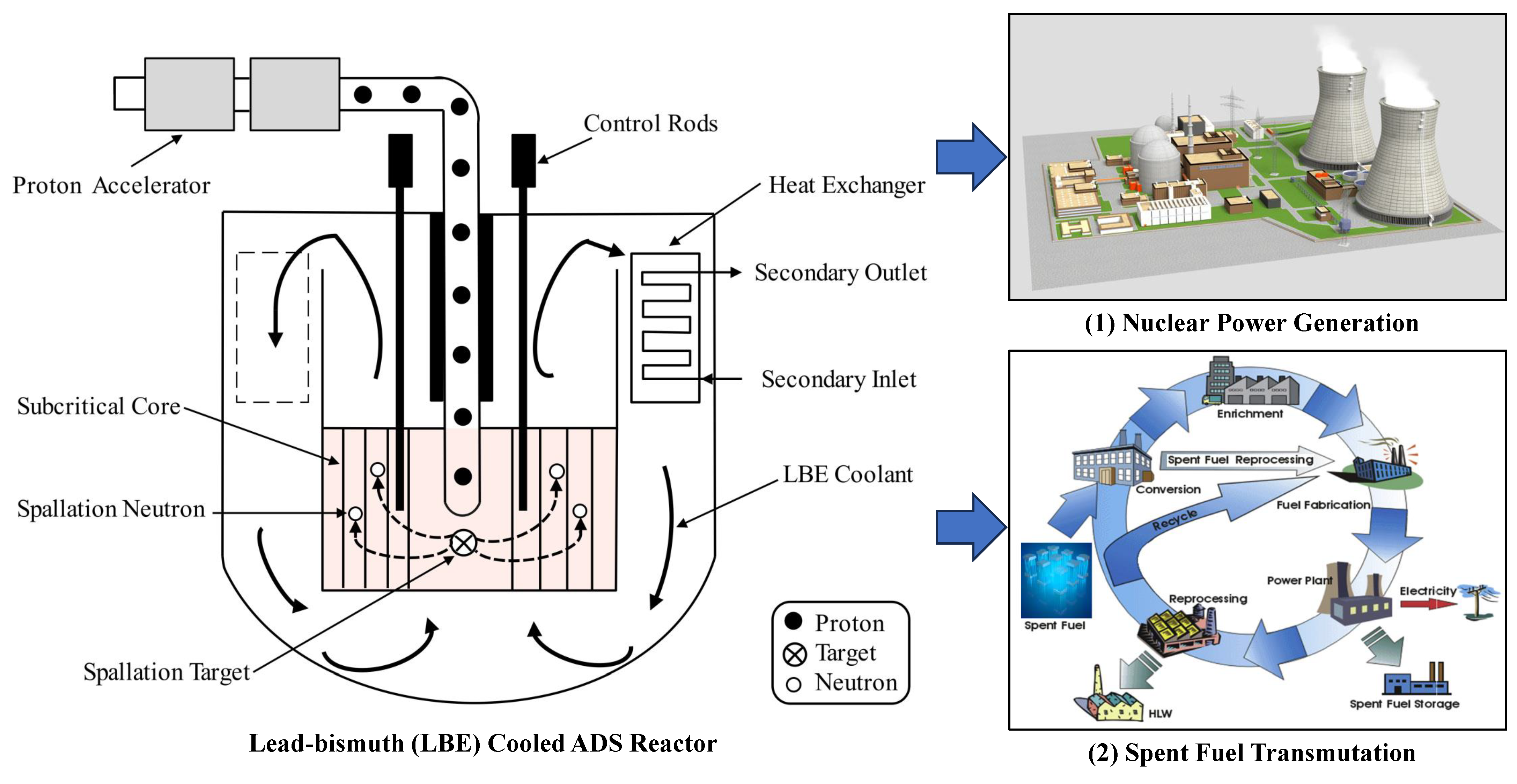
2. LBE-Cooled Reactor Dynamic Model

This study focuses on the Italian 80 MW LBE-cooled reactor to investigate the control characteristics of an ADS device [24]. The LBE-cooled ADS reactor comprises a subcritical reactor core, a proton accelerator, and a liquid metal spallation target, as shown in Figure 1. This reactor is designed for both nuclear power generation and spent fuel transmutation. As illustrated in Figure 1, the accelerated proton beam is directed into the target, where it bombards the LBE metal to induce a spallation reaction. The neutrons generated from this reaction are then delivered to the subcritical reactor core, sustaining the fission chain reaction. A reactor’s power adjustments can be made by varying the beam intensity to change the neutron source intensity or by moving the control rod assembly to alter the reactor core reactivity. The heat produced in the core is transferred by the LBE coolant. In the heat exchanger (IHX), the primary coolant is high-temperature LBE, while the secondary coolant consists of an organic diathermic fluid. Previous studies have established and validated a one-dimensional space–time neutron diffusion equation, integrated with a reactor thermohydraulic model and a heat exchanger dynamic model [25].

2.1. Space–Time Neutron Diffusion Model

While a three-dimensional neutronic dynamic model of the reactor core provides high accuracy and detailed information, it demands significant data storage and long computation times. For certain calculations, such as reactor control system design and load following simulation, detailed radial data of the reactor core may not be necessary because of the radially symmetric arrangement of the fuel assemblies and control rod groups [26]. Therefore, without reducing the calculation accuracy, the axial one-dimensional neutron diffusion model would be more desirable, which is as follows:
1 v a ϕ ( z , t ) t = D 2 ϕ ( z , t ) Σ a ϕ ( z , t ) + ( 1 β ) ν Σ f ϕ ( z , t ) + j = 1 6 λ j C j ( z , t ) + S ( z , t )
C j ( z , t ) t = β j ν Σ f ϕ ( z , t ) λ j C j ( z , t ) ; j = 1 , 2 , , 6
where v a denotes the average neutron speed, ϕ represents the neutron flux, z is the axial position, t stands for time, D is the diffusion coefficient, and Σ a and Σ f are the macroscopic absorption and fission cross sections, respectively. Additionally, ν is the number of neutrons for each fission, S is the neutron source from spallation reaction, β j denotes the delayed neutron fraction, and C j and λ j are the concentrations and decay constants of the delayed neutron precursors, respectively.
Figure 1. Overview and purpose of the LBE-cooled ADS reactor.
Energies 18 00567 g001

2.2. Reactor Thermohydraulic Model

During normal reactor operation, the fission energy produced by the nuclear fuel is transferred from the fuel pellet to the cladding and subsequently from the cladding to the coolant. A single-channel model is employed for thermal-hydraulic calculations, which encompass heat conduction within the fuel element and heat transfer from the cladding to the coolant. The heat conduction equation for the fuel pellet can be expressed as
ρ f C f T f ( r , t ) t = 1 r r r k f T f ( r , t ) r + q v
where ρ f and C f represent the fuel pellet density and specific heat, respectively, T f and k f are the fuel pellet temperature and heat conductivity, respectively, and q v denotes the volumetric heat rate.
The heat conduction equation for the cladding could be calculated by
ρ c l C c l T c l ( r , t ) t = 1 r r r k c l T c l ( r , t ) r
where ρ c l and C c l represent the cladding density and specific heat, respectively; T c l and k c l denote the cladding temperature and heat conductivity.
The heat transfer from cladding to coolant along the reactor axis direction can be described by the basic mass and energy conservation equations as
ρ c V c C c d T c d t = h c l , c A c l , c T c l r = r c l T c G c C c T c , o u t T c , i n
where ρ c , V c , C c and T c represent the coolant density, volume, specific heat and temperature, respectively, h c l , c is the coefficient of heat transfer from the cladding to the coolant, A c l , c denotes the area of heat transfer from the cladding to the coolant, G c is the coolant mass flow rate, and T c , i n and T c , o u t represent inlet and outlet temperatures of the reactor coolant, respectively.

2.3. Heat Exchanger Dynamic Model

The primary coolant exits the reactor core and enters the heat exchanger via the ascending channel. After transferring its heat to the organic diathermic fluid on the secondary side, the primary coolant flows down to the lower plenum. The heat transfer models for the primary coolant, tube wall, and secondary coolant are described as follows:
V p ρ p C p d T p d t = G p C p ( T p , i n T p , o u t ) h p , w A p ( T p T w )
V w ρ w C w d T w d t = h p , w A p ( T p T w ) h s , w A s ( T w T s )
V s ρ s C s d T s d t = h s , w A s ( T w T s ) G s C s ( T s , o u t T s , i n )
where h p , w represents the coefficient of heat transfer from the primary coolant to the tube wall; h s , w denotes the coefficient of heat transfer from the tube wall to the secondary coolant.

3. Collaborative Control and Intelligent Optimization Method

The LBE-cooled ADS reactor differs from critical fast reactors, resulting in a unique control strategy and system design. For instance, the ability to adjust the reactor’s power by varying the accelerator beam intensity to change the spallation neutron source is not present in traditional reactors, and this beam intensity adjustment poses a complex engineering challenge. The beam intensity is difficult to accurately achieve the desired value during actual engineering operation, and the accelerator beam may become unstable during operation [27]. Therefore, the beam intensity could be used to roughly adjust the reactor’s power, i.e., to define the relationship between beam intensity and desired power for designing an accelerator beam control strategy, so as to achieve power control. On the other hand, due to the integration of an accelerator, spallation target, and subcritical core in the ADS device, the accelerator channel takes up substantial space within the core, thereby restricting the number of control rod assemblies that can be installed. The control rod regulation method of a reactor’s power has accumulated practice experience in traditional critical reactors and has mature technical foundation [28]. Therefore, the design of fast reactors’ control rods could be used as a reference to achieve precise regulation of the reactor’s power.
In this study, based on the special property of the LBE-cooled ADS reactor that could be controlled by both spallation neutron source and reactivity, a new strategy for reactor power control is proposed by using accelerator beam and control rod. Referring to the arrangement of the accelerator beam channel and fuel assembly in the XADS core [29] and the setting of the control rod assembly in the MYRRHA core [30], the designed reactor core arrangement with accelerator beam and control rod assembly is presented in Figure 2. The accelerator beam and spallation target are positioned at the center of the reactor’s core. During steady-state operation, the neutrons produced by the proton beam and target are supplied to the subcritical core to sustain the neutron chain fission reaction. As the reactor needs to adjust the reactor’s power, the beam intensity in the accelerator could be adjusted to change the flux of the spallation neutron source to achieve reactor power control. The proton energy produced by the accelerator in this study is 600 MeV, and the proton beam intensity is 2.5 mA [27]. The control rod assembly is symmetrically arranged around the fuel assembly. This arrangement is mainly utilized to avoid distortion of radial power distribution when the control rod assembly moves up and down for reactor power adjustment. The material of the control rod is B4C (80% 11B and 20% 10B) neutron absorber material [7].

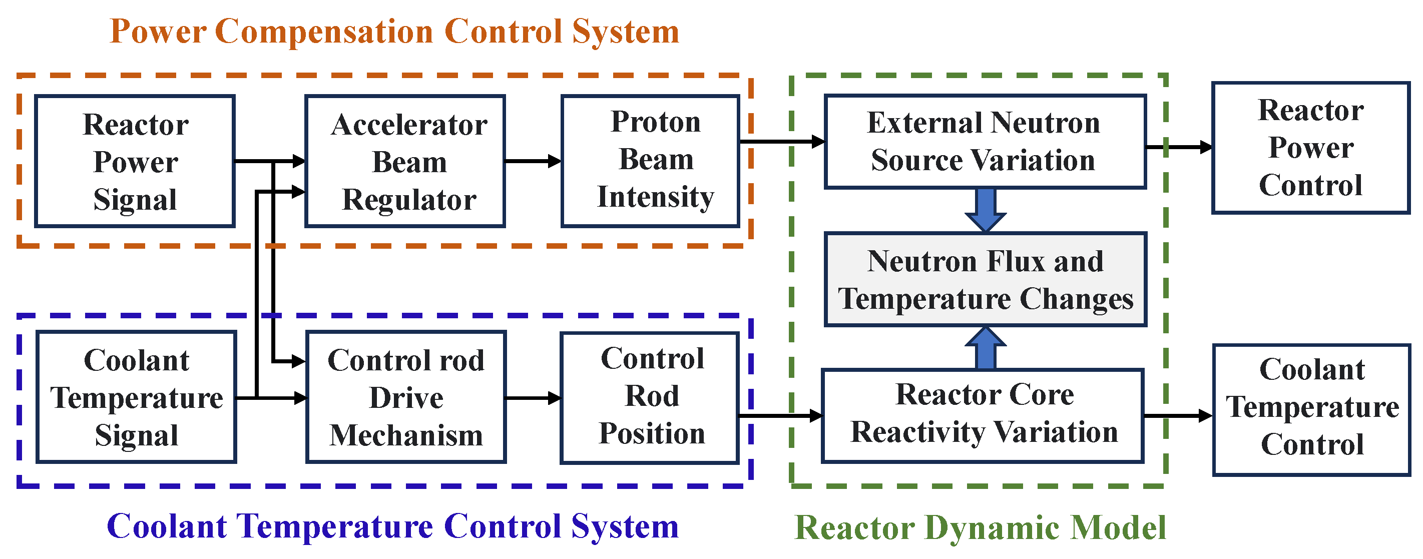
3.1. Collaborative Control Strategy

At present, the ADS reactor’s power is controlled by either using accelerator beam to adjust the spallation neutron source or only through adopting control rod to adjust the reactivity. However, due to the complexity of accelerator technology, it is difficult to achieve precise control by beam intensity alone. At the same time, single-beam control would inevitably lead to more accelerator adjustment actions, which is not conducive to the utility of equipment. The ADS reactor is subcritical and is less sensitive to the introduced reactivity, so the impact of the control rod on the ADS reactor is much smaller than that on the critical reactor. If control rods are used exclusively to adjust the reactor’s power over a wide range, their total integral worth will be high, necessitating a large number of control rod assemblies. This is not only uneconomical but also makes the control system structure extremely complex and not conducive to engineering implementation. Therefore, a new collaborative strategy is proposed for reactor power control by combining the advantages of these two control approaches, as shown in Figure 3.
As can be seen from Figure 3, the power compensation control system handles coarse adjustment by varying the accelerator beam intensity to modulate the spallation neutron source, bringing the actual power closer to the desired value. For fine adjustment, the coolant temperature control system is used, where the control rod position is altered to adjust the neutron absorption cross-section in the reactor core, thereby modifying reactivity for precise power control.
This control mode combines the advantages of both the accelerator and the control rod, because when the actual power is far from the setting power, the efficiency of accelerator beam regulation is higher than that of the control rod, and the number of control rod assemblies could be reduced. As the actual power is close to the setting power, the effect of the control rod for precise adjustment is better than the accelerator beam, thereby making up for the defects of the accelerator beam control alone.

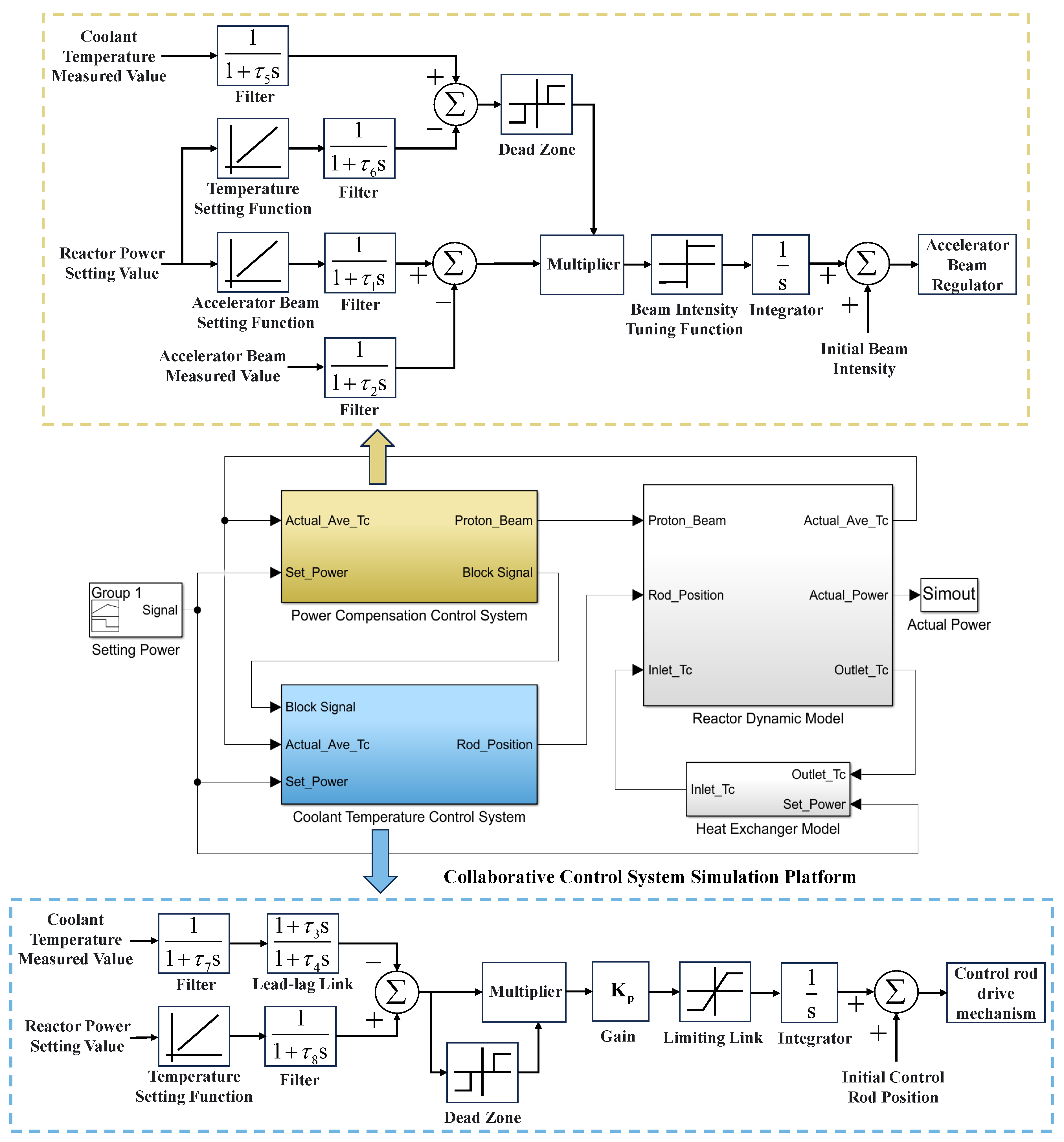
3.2. Collaborative Control System Design

To demonstrate the benefits of the new control strategy, a simulation platform is developed using a nonlinear reactor dynamic model, along with the power compensation and coolant temperature control systems. This platform, built in MATLAB/Simulink, is used to evaluate the performance of the control system, as shown in Figure 4.

3.2.1. Power Compensation Control System

In the power compensation control system, beam intensity is adjusted based on the reactor’s power to achieve coarse power control. The relationship between power level and beam intensity is represented by the effective calibration curve, which is derived from steady-state reactor core operation at various power levels. During power control, the beam intensity is set according to this calibration curve, as illustrated in Figure 4. The beam intensity is then adjusted at a constant rate until it matches the calibration value. This system operates in an open-loop mode, as there is no feedback on the actual power of the reactor core. The principle block diagram is shown in Figure 4.
The power compensation control system converts the power setting value into the beam intensity setting value according to the load change demand. The beam intensity value is filtered with a time constant of τ 1 and then compared with the measured actual beam intensity after filtering with a time constant of τ 2 to generate a beam intensity deviation signal. The beam deviation signal is passed through the beam change rate function to generate a beam change signal, i.e., a beam increase and decrease signal and a change rate signal. This signal is sent to the proton accelerator injection equipment to adjust the beam intensity in response to the required load. In order to prevent unnecessary and frequent operation of the accelerator control equipment, a temperature dead zone that prohibits beam changes is designed in the power compensation control system. When the difference between the actual and set values of the coolant average temperature falls below the threshold, the threshold relay sends a command to prohibit beam changes, so that the accelerator beam adjustment device does not operate.

3.2.2. Coolant Temperature Control System

The control rod moves fast, operates flexibly and reliably, and has high control accuracy for reactivity. Therefore, the control rod is employed to regulate the coolant temperature, ensuring precise alignment between the reactor’s power and the required load. The average coolant temperature is one of the main regulating variables for reactor power control, and its variation could reflect the mismatch between the set power and the actual power. The new control strategy proposed in this paper is to adjust the coolant temperature with the control rod, which is used to cooperate with the power compensation control of the accelerator beam to achieve the final reactor power control. This control method leverages the strengths and benefits of both approaches. The coolant temperature control system is a closed loop that takes into account the actual coolant temperature feedback, as shown in Figure 4.
As shown in Figure 4, the input signals to the coolant temperature control system include the power set value, reflecting the demand load, and the measured coolant average temperature. During load regulation, discrepancies between the actual reactor’s power and the required load generate a temperature deviation signal. This signal then passes through the gain and rod speed-limiting links, producing a control rod movement signal (either insertion or withdrawal). This signal is sent to the control rod drive mechanism, enabling the rod to move within the reactor core, thereby adjusting the reactor’s power. The average temperature measurement serves as the feedback channel for the control system. To address the temperature lag caused by thermal inertia, a lead-lag link is implemented, generating both lead and lag signals. Based on the steady-state operation scheme, the coolant temperature setting value can be determined from the power set value. A filter is used to eliminate noise from the coolant temperature signal, preventing unnecessary rod movements during power control. The limiting link ensures that control rod movement remains within safe limits, avoiding excessive power fluctuations. To prevent frequent rod actuation due to minor temperature deviations, a dead zone link is introduced. When the deviation is below a set threshold, the control rod drive mechanism remains inactive.

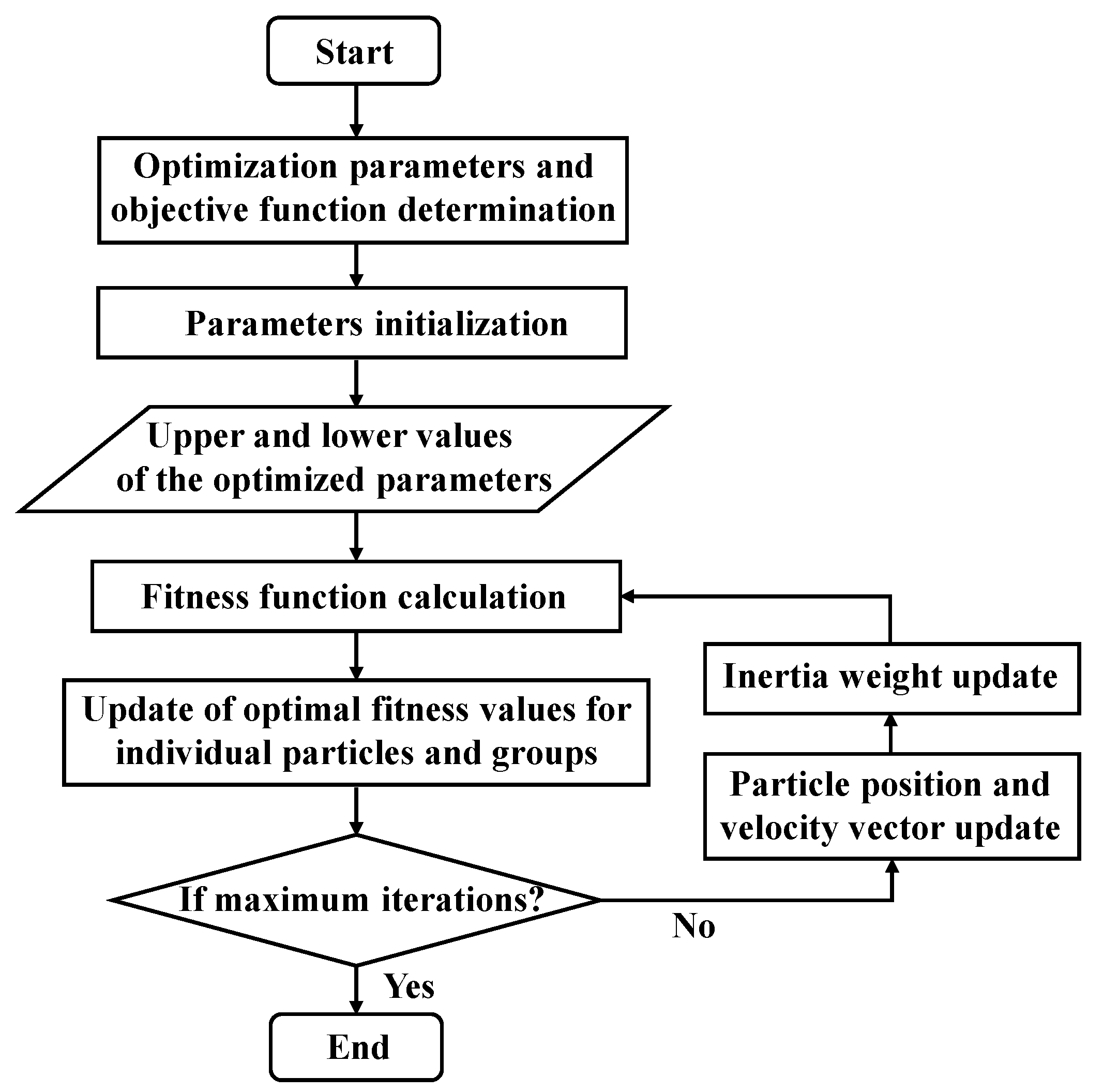
3.3. Controller Parameter Optimization Method

To optimize the control system parameters and enhance control system performance, the Linear Decreasing Inertia Weight Particle Swarm Optimization (LDIW-PSO) algorithm is employed for multi-objective optimization [31]. In this paper, each potential solution is represented as a particle in an n-dimensional search space. Each particle moves through the space at a specific speed, updating its position based on both its individual best position (optimal fitness value) and the group’s best position (global optimal fitness value) [32]. A particle group G p = { x 1 , x 2 , , x m } consisting of m particles is set in the n-dimensional target search space. During the optimization process, the position and velocity of the i-th particle at the k-th iteration, along with its individual optimal fitness value, can be expressed as x i = { x i 1 k , x i 2 k , , x i n k } T , v i = { v i 1 k , v i 2 k , , v i n k } T and p i = { p i 1 k , p i 2 k , , p i n k } T . The global optimal fitness value of all particles at the k-th iteration is p g = { p g 1 k , p g 2 k , , p g n k } T . If new individuals and global optimal fitness values are found in this generation, the particle updates its velocity and position using the following formula:
v i j k + 1 = v i j k + c 1 r 1 k ( p i j k x i j k ) + c 2 r 2 k ( p g j k x i j k ) , j = 1 , 2 , , n
x i j k + 1 = x i j k + v i j k + 1
where c 1 denotes individual learning factor, c 2 denotes global learning factor, and r 1 and r 2 represent random values between 0 and 1.
To enhance the PSO optimization ability by balancing its local and global search capabilities, Shi proposed the LDIW-PSO algorithm [33], which achieved better optimization results. During the calculation process, the original particle velocity Equation (9) is modified with the following formula:
v i j k + 1 = w v i j k + c 1 r 1 k ( p i j k x i j k ) + c 2 r 2 k ( p g j k x i j k ) , j = 1 , 2 , , n
The inertia weight w in the above formula is given by
w = w m a x N p r e ( w m a x w m i n ) N m a x
where w m a x denotes maximum inertia factor, w m i n represents minimum inertia factor, N p r e denotes current iteration number, and N m a x represents maximum iteration number.
The LDIW-PSO algorithm enables particles to have stronger global search capabilities and a larger search range at the beginning of the calculation, as well as stronger local search capabilities and faster convergence speed in the later stage of the calculation, thereby improving the optimization performance. Therefore, the LDIW-PSO method is applied to optimize the collaborative control system, and its calculation process is shown in Figure 5.

4. Results and Discussion

To test the performance of the control system, the accelerator Beam Rod Collaborative-Control (BRCC) strategy proposed in this work is compared with the other control strategies in the literature, namely the control Rod Single-Control (RSC) strategy and the accelerator Beam Single-Control (BSC) strategy. Four typical transient operating conditions are selected for comparative analysis: (1) 10% full power (FP) step load reduction; (2) 10% FP step load increase; (3) 5% FP/min linear load reduction; (4) 5% FP/min linear load increase.

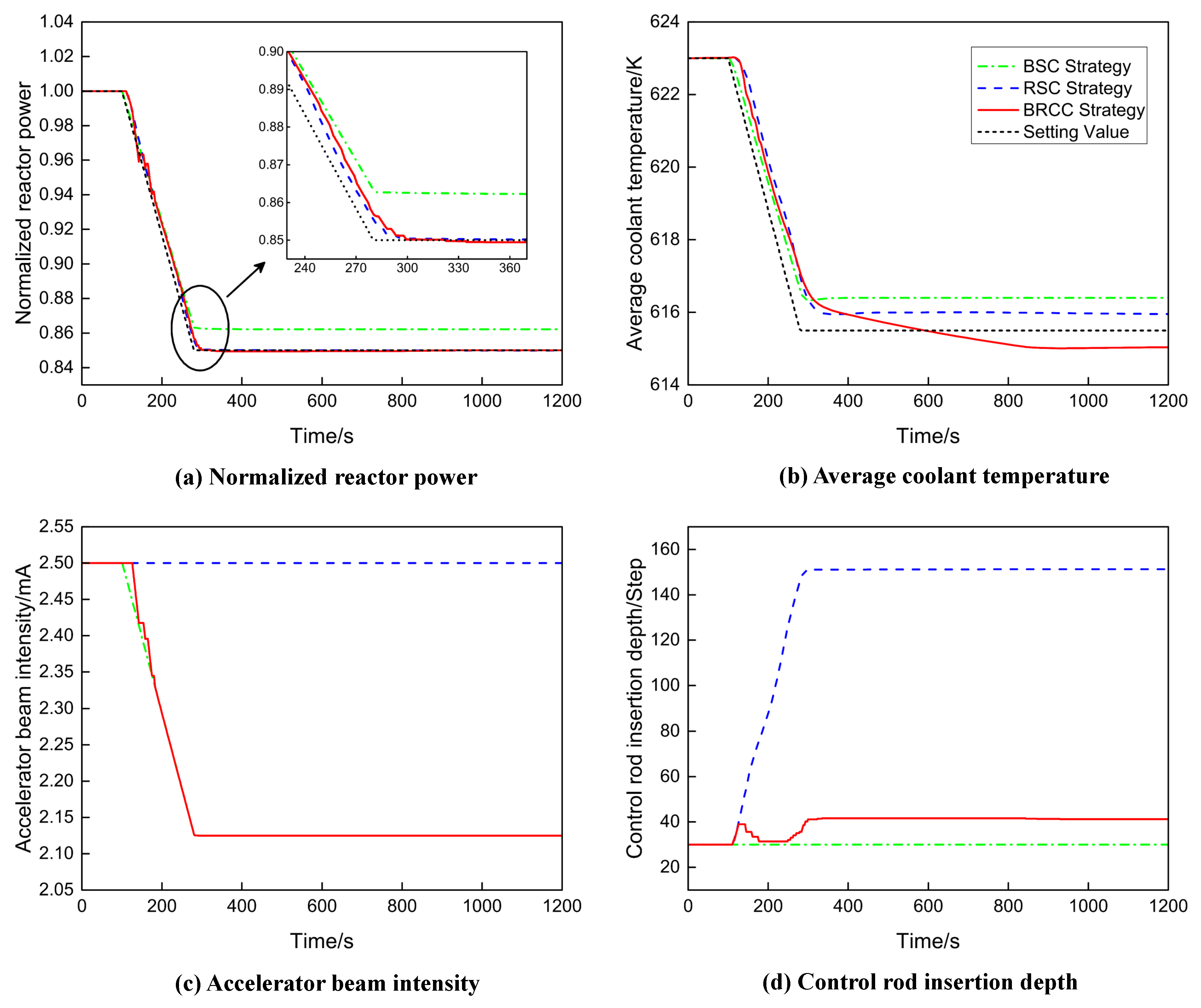
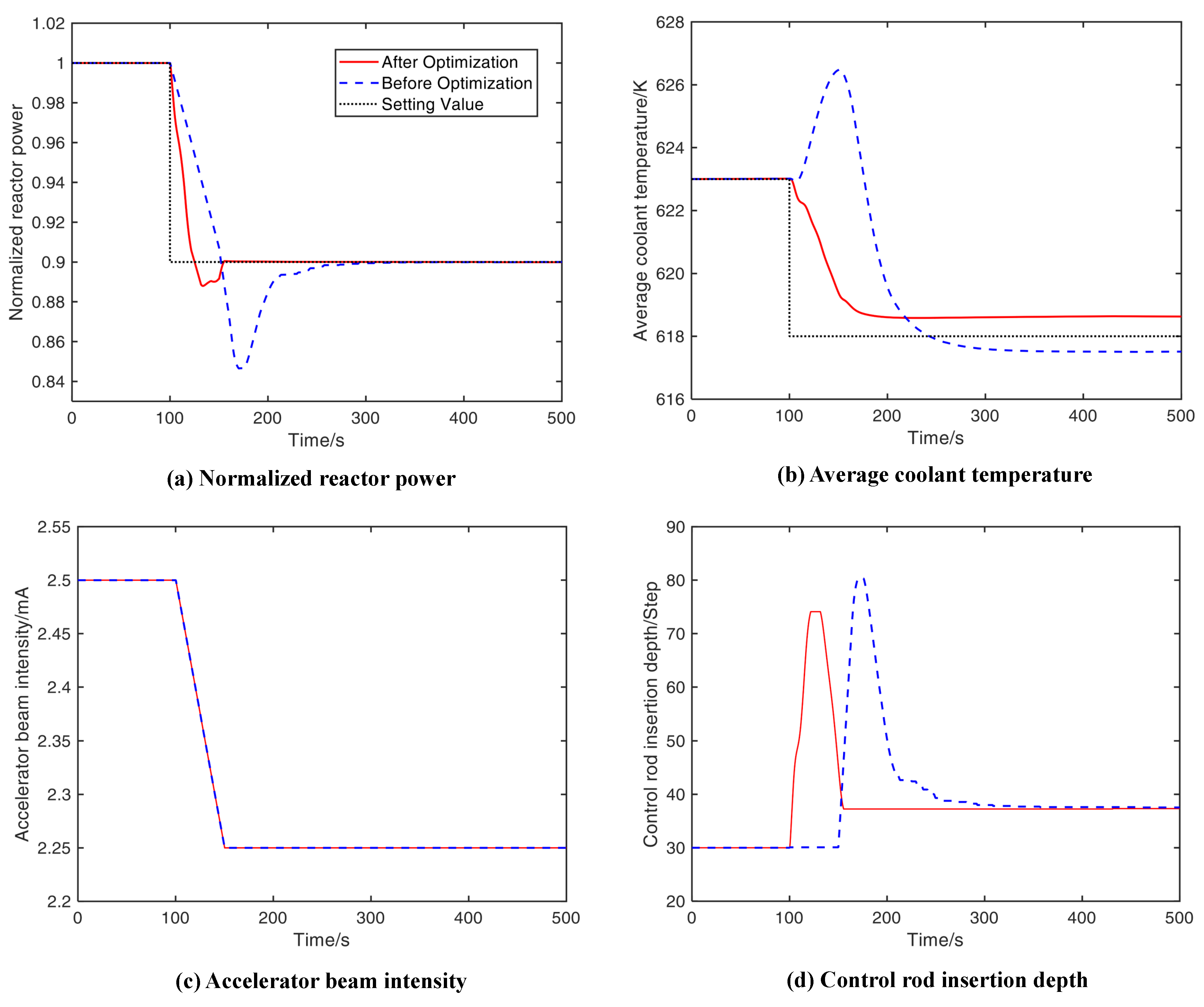
4.1. Step Load 10% FP Reduction

The transient simulation time is 500 s. The reactor first maintains full power steady-state operation. At 100 s, the power load is set to step down from 100% FP to 90% FP. In this transient process, the simulation results of the reactor’s power, average coolant temperature, beam intensity and control rod insertion depth based on three different control strategies are presented in Figure 6.
As shown in Figure 6, for the BRCC strategy, at the moment of load step reduction, the power compensation control system generates a reduction signal of the beam intensity due to power mismatch, thereby reducing the neutron flux density, in which the reactor’s power is reduced. Meanwhile, the heat removed from the reactor core by the heat exchanger decreases rapidly, causing the average coolant temperature to rise. As the beam intensity continues to decrease, the reactor’s power declines, and the average coolant temperature eventually drops after an initial increase. Due to temperature hysteresis, the beam stops adjusting once the core power reaches the target value. However, since the temperature deviation remains above the dead zone, the control rod is inserted, further reducing the power. The power then gradually rises again due to the Doppler effect and coolant temperature feedback, stabilizing at the set value, and all control systems cease operation. In the RSC strategy, only the control rod is used throughout the transient process, with the reactor’s power and coolant temperature changes resembling those of the BRCC strategy. The BSC strategy, an open-loop control method, fails to precisely adjust the reactor’s power, leading to a significant deviation.
In the transient simulation of step load reduction, the adjustment amount of the control rod of the BRCC strategy is much smaller than that of the RSC strategy. Meanwhile, the number of steps required for control rod insertion is relatively small. In addition, the overshoot of the BRCC strategy and the RSC strategy is 5.93% and 6.45%, respectively. The tuning time of the BRCC strategy and the RSC strategy is 237 s and 296 s, respectively, as shown in Figure 6a. These results show that the overshoot of the proposed BRCC strategy is smaller than the RSC strategy and its adjustment time is shorter. Compared with the BSC strategy, the BRCC strategy has the same beam adjustment amount, but the BRCC strategy can achieve fine adjustment of the reactor’s power, while the BSC strategy has control deviation. These results indicate that the BRCC strategy outperforms both the RSC and BSC strategies in terms of control performance and requires less of an adjustment of the control mechanism.

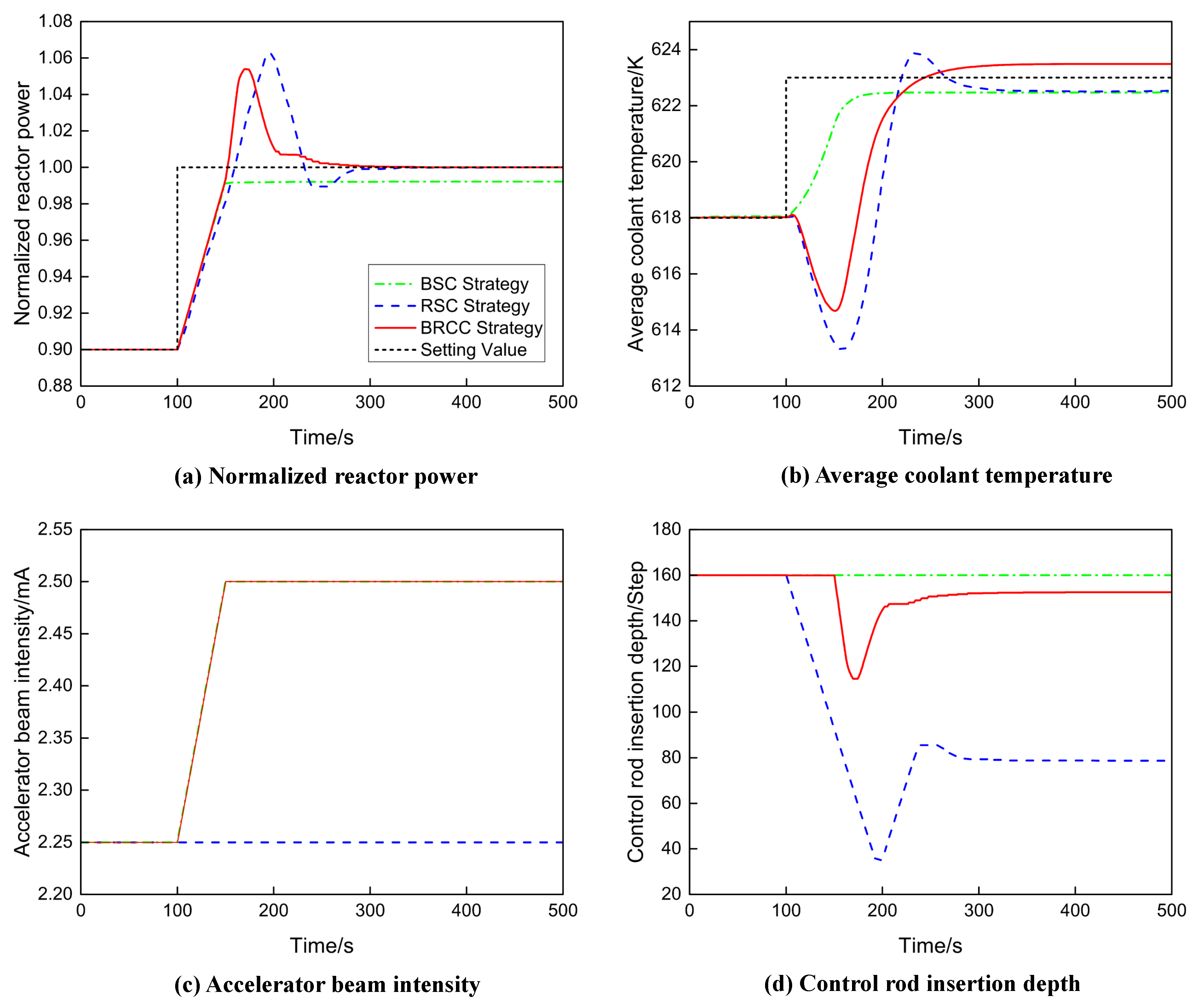
4.2. Step Load 10% FP Increase

In this transient condition, the power load is stepped up from 90% FP to 100% FP at 100 s. The results are presented in Figure 7. For the BRCC strategy, when the load demand increases, the power compensation control system adjusts the beam intensity upwards to address the reactor’s power mismatch, thereby boosting neutron flux density and increasing the reactor’s power. Meanwhile, the heat transferred from the reactor core to the heat exchanger rises quickly, causing the average coolant temperature to drop. As beam intensity continues to increase, the reactor’s power increases further, and the average coolant temperature eventually increases after initially decreasing. Due to the temperature lag, the beam intensity adjustment stops once the reactor’s power reaches the target value. If the average temperature deviation exceeds the dead zone threshold, the control rod continues to draw out, further raising the reactor’s power. The power peaks due to negative reactivity feedback and then gradually decreases, stabilizing at 100% FP, after which the control systems stop action.
The parameter change process of the RSC strategy for the reactor power control is similar to the BRCC strategy, but the adjustment amount of the control rod is much larger, and the adjustment time is also longer than the BRCC strategy. The BSC strategy could not achieve precise adjustment of the reactor’s power.

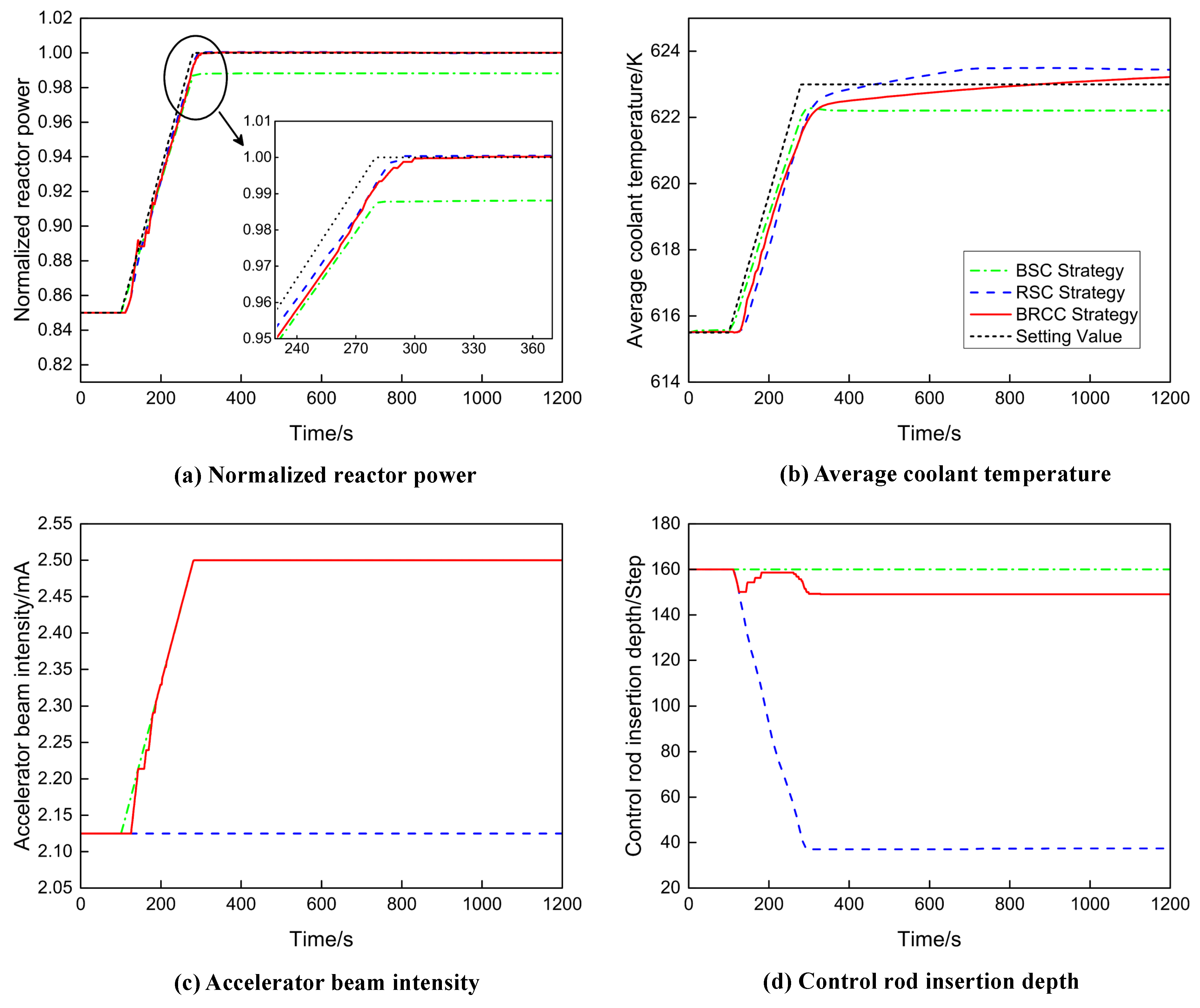
4.3. Linear Load 5% FP/min Reduction

The transient simulation lasts for 1200 s. At 100 s, the power load is reduced linearly from 100% FP to 85% FP at a rate of 5% FP/min. The simulation results for the reactor’s power, average coolant temperature, beam intensity, and control rod insertion depth under three different control strategies are presented in Figure 8.
From the calculation results, it is evident that during the linear load reduction in the BRCC strategy, the power compensation control system and the coolant temperature control system work together effectively to adjust the reactor’s power, demonstrating good load-following performance. Additionally, the average coolant temperature changes in line with the reactor’s power set point, eventually stabilizing at the target value. For the RSC strategy, only the control rod is used for power control throughout the entire process, with the reactor’s power and coolant temperature variations similar to those in the BRCC strategy. In contrast, the BSC strategy shows a larger control deviation compared to the BRCC strategy.
As shown in Figure 8, during the linear load reduction process, the movement range of control rod for the BRCC strategy is very small, mainly focusing on the adjustment of the accelerator beam, and the control performance is good. However, the control rod insertion depth required by the RSC strategy is very large, which proves that the efficiency of using only the control rod to adjust the power load for the LBE-cooled ADS reactor is relatively low. Therefore, the RSC strategy needs a large integral worth of the control rod for a large range of power adjustments, resulting in the requirement of a large number of control rod assemblies, which is not only uneconomical but also makes the system structure particularly complex and is not conducive to engineering implementation. Compared with the BSC strategy, the BRCC strategy has a similar beam adjustment process, and the BRCC strategy can track the load variation better and achieve accurate control of the reactor’s power.

4.4. Linear Load 5% FP/min Increase

In this control transient, the power load is increased linearly from 85% FP to 100% FP at a rate of 5% FP/min at 100 s. The simulation results are presented in Figure 9. For the BRCC strategy, during the linear load increase process, the power compensation control system and the average temperature control system coordinate with each other, and the reactor’s actual power tracks the variation of the setting power value very well. Meanwhile, the variation trend of the average coolant temperature matches the trend of reactor power variation, and the actual temperature value is finally stabilized near the setting value. The simulation results show that the adjustment amount of the control rod for the BRCC strategy is very small, and the control effect is good. However, the total step number of control rod required for the RSC strategy is large, and the efficiency of the control rod is relatively low. The BSC strategy has a relatively poor ability to track the demand load and has control deviation.
The results of these four transients demonstrate that the BRCC strategy proposed and the control system designed in this paper could achieve accurate control of the ADS reactor’s power. Compared with RSC and BSC control strategies, the BRCC strategy has better control effect and requires less adjustment amount of the control mechanism.

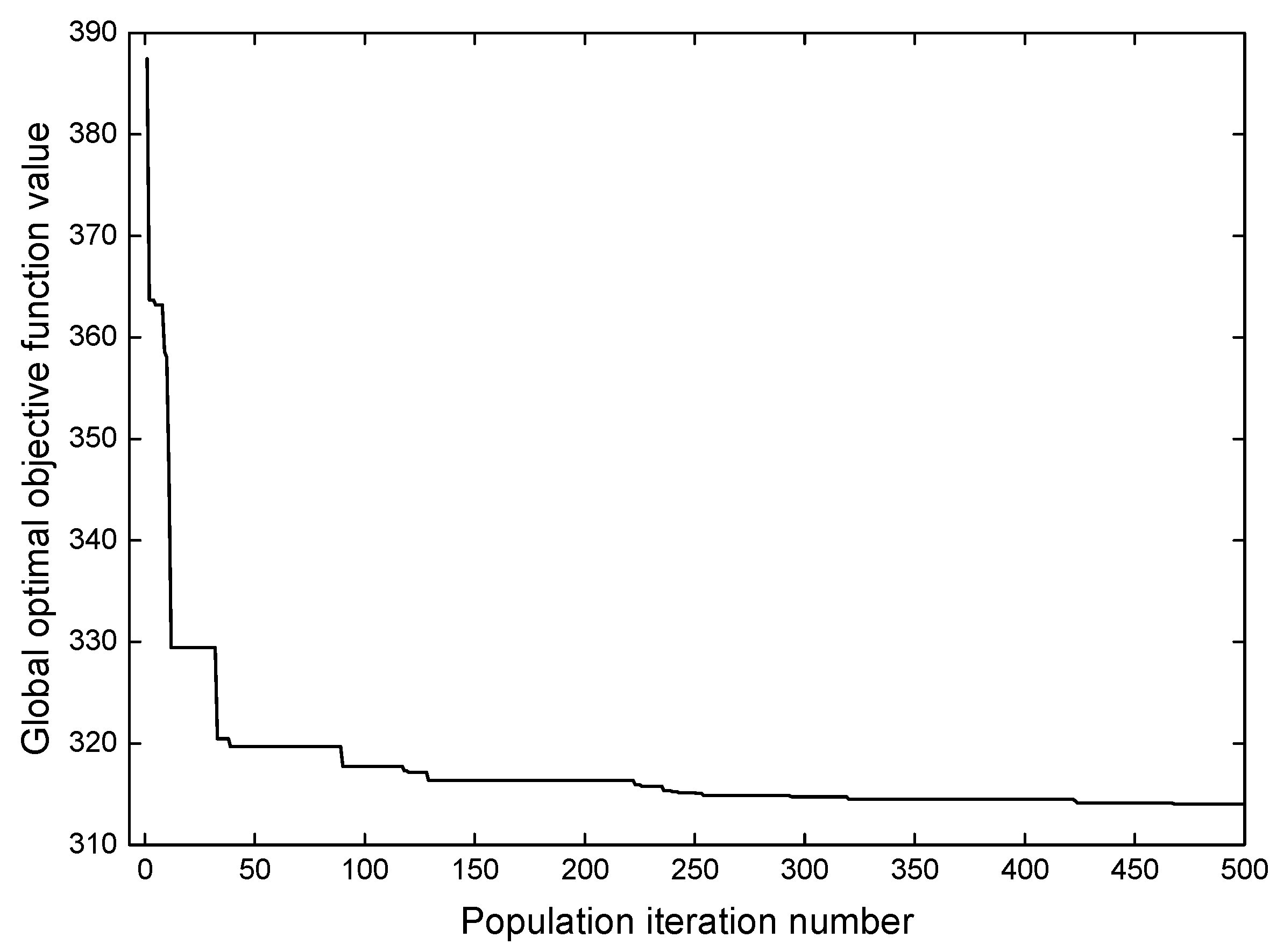
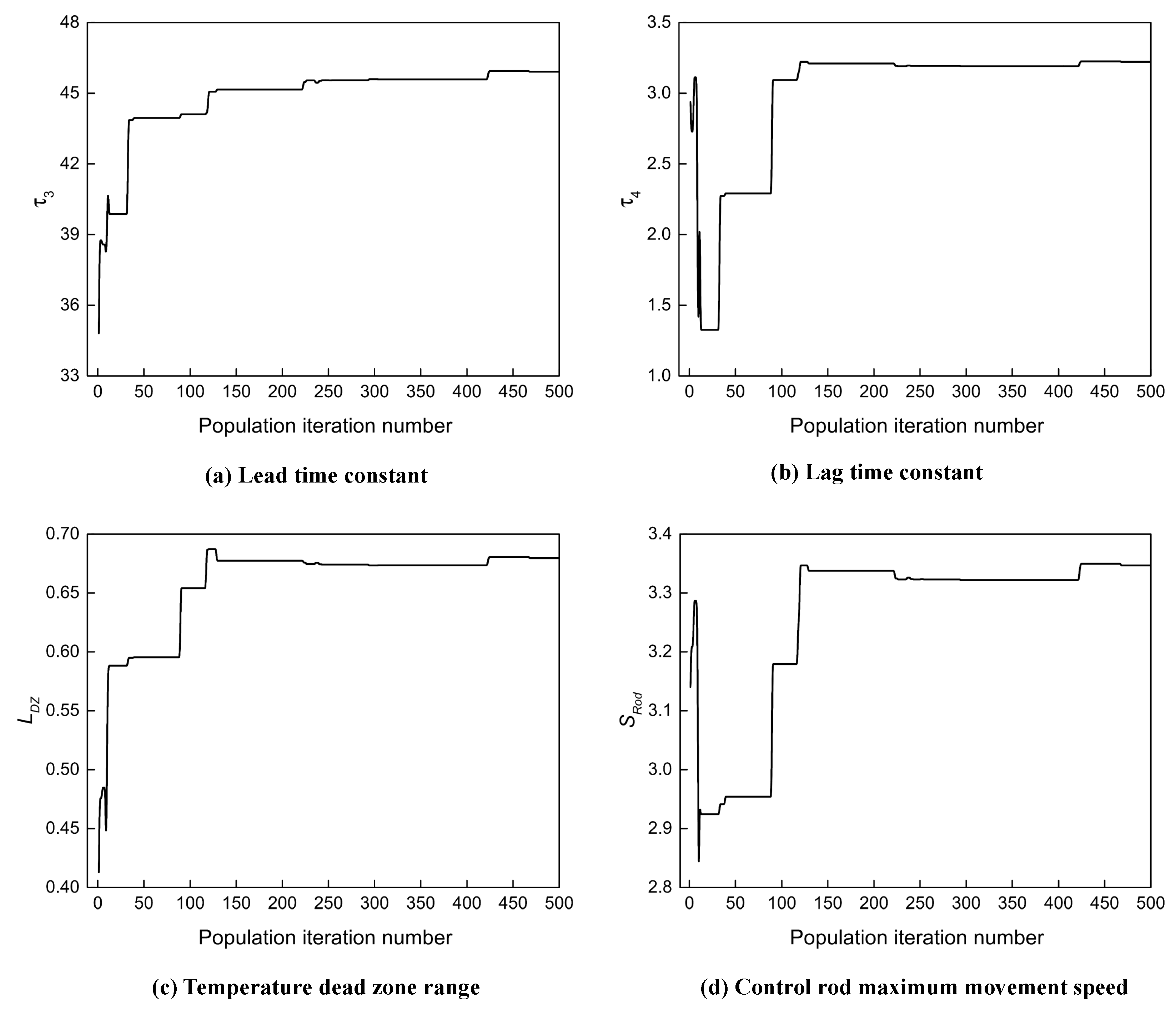
4.5. Controller Parameter Optimization Result

The beam regulation function in the power compensation system is determined according to the accelerator operation plan; thus, its parameter is no longer optimized. In this study, several key control parameters of the coolant temperature control system are selected for intelligent optimization, as these parameters have an important influence on the performance of the entire collaborative control system. First, the lead-lag link ( τ 3 > τ 4 ) can be used to compensate for the response lag caused by the thermal inertia of the measurement channel and provide an advance signal, which significantly influences the dynamic response of the reactor core. Then, the temperature dead zone link ( L D Z ) can avoid frequent movements of the control rod caused by small disturbances in the average coolant temperature, which is beneficial to the service life of the control rod drive mechanism and enhances system stability. In addition, the rod speed limit link ( S R o d ) can limit the maximum adjustment speed of the control rod so that the control rod does not move too fast and cause drastic changes in the reactor’s power. Therefore, these four control parameters [ τ 3 , τ 4 , L D Z , S R o d ] are taken as the optimization objects, and the LDIW-PSO algorithm is used to perform global optimization.
The main goals of controller parameter optimization are as follows: to improve the performance of the reactor power control system; to minimize the power deviation and improve the response speed; and to minimize the actions number of the control mechanism. Therefore, the objective function is set as follows:
f o b j = ω p 0 τ t P s e t ( t ) P a c t ( t ) d t + ω r R s t e p s
where P s e t is the setting power value, P a c t is the actual power value, ω p is the weighting coefficient of power control error, ω r is the weighting coefficient of control rod adjustment amount, and R s t e p s is the total number of control rod adjustment steps. To balance the control quality and control cost, ω p = 1 and ω r = 2 . The parameters of the LDIW-PSO algorithm are listed in Table 1.
The process of optimizing controller parameters is illustrated in Figure 10 and Figure 11. The optimization results show that the global optimal target value gradually decreases from an initial value of 387.4 to 314.1 during the optimization process. The objective function value is reduced by about 18.9%, which means that the optimization effect is very obvious. As shown in Figure 11, the best combination of control parameters is [ τ 3 = 45.91 , τ 4 = 3.22 ,   L D Z = 0.68 ,   S R o d = 3.35 ] .
The comparison results of the control performance before and after optimization are presented in Figure 12. As can be seen from Figure 12a, after the controller parameters are optimized by the LDIW-PSO algorithm, the dynamic response characteristics of the reactor’s power are significantly improved. Moreover, the deviation between the actual power and its set value is reduced, the adjustment time of the reactor’s power is shortened, and the overshoot is reduced. As shown in Figure 12b, the dynamic response curve of the average coolant temperature after optimization is smoother. As shown in Figure 12c,d, the number of control rod adjustment steps is reduced when the beam adjustment amount remains unchanged.
In order to more intuitively compare the control system performance before and after optimization, the comparison of the main performance indicators before and after optimization is shown in Table 2. The indicators include the mean square error (MSE), integral time absolute error (ITAE) [34], overshoot and tuning time.
As shown in Table 2, in terms of control quality, the MSE and ITAE values of the reactor’s power after optimization are significantly reduced, and the overshoot is greatly reduced, while the adjustment time is significantly improved. In terms of control cost, the total number of control rod adjustment steps is reduced, which reduces the mechanical wear of the control rod during power regulation. These results show that the control performance after optimization is significantly improved, which demonstrates the effectiveness of the LDIW-PSO algorithm in optimizing the ADS reactor controller parameters.

5. Conclusions

The ADS reactor exhibits distinct dynamic behaviors and control mechanisms compared to conventional nuclear reactors. This paper introduces a novel collaborative control approach that integrates the accelerator beam and control rod. Furthermore, a simulation platform incorporating a nonlinear reactor dynamic model, a power compensation control system, and a coolant temperature control system is developed, with the controller parameters being optimized using the LDIW-PSO method.
Four typical control transients are carried out, including ±10% full power (FP) step change load and ±5% FP/min linear variable load. These simulation results show that the proposed BRCC strategy and the designed control system can achieve accurate control of the ADS reactor’s power. Compared with the RSC and BSC control strategies, the BRCC strategy has a better control effect and requires a lower adjustment of the control mechanism. The results also show that the performance of the collaborative control system for reactor’s power and coolant temperature was significantly improved based on modified PSO parameter optimization. In terms of control quality, the MSE and ITAE values of the reactor’s power after optimization were significantly reduced, and the overshoot was greatly reduced, while the adjustment time was significantly improved. In terms of control cost, the total number of control rod adjustment steps was reduced, reducing the mechanical wear of the control rod during power regulation.

Author Contributions

Conceptualization, S.Y. and R.L.; methodology, S.Y., L.Z. and R.L.; software, S.Y., L.S. and R.L.; validation, S.Y., H.G. and J.W.; formal analysis, S.Y. and R.L.; investigation, S.Y. and R.L.; resources, S.Y. and R.L.; data curation, H.G. and J.W.; writing—original draft preparation, S.Y., L.Z., L.S. and R.L.; writing—review and editing, S.Y., F.Z. and R.L.; visualization, S.Y. and R.L.; supervision, R.L.; project administration, R.L.; funding acquisition, R.L. All authors have read and agreed to the published version of the manuscript.

Funding

This study was supported by the Natural Science Foundation of Hunan Province, China (No. 2023JJ50122); the International Cooperative Research Project of the Ministry of Education, China (No. HZKY20220355); the Scientific Research Foundation of the Education Department of Hunan Province, China (No. 22A0307); and the Innovation Training Program for College Students (No. S202410555084 and No. S202410555134).

Data Availability Statement

Data are contained within this article; further inquiries can be directed to the corresponding author.

Conflicts of Interest

S.Y., L.Z. and L.S. were employed by China Institute of Nuclear Industry Strategy. The remaining authors declare that the research was conducted in the absence of any commercial or financial relationships that could be construed as a potential conflict of interest.

References

  1. Alwaeli, M.; Mannheim, V. Investigation into the current state of nuclear energy and nuclear waste management—A state-of-the-art review. Energies 2022, 15, 4275. [Google Scholar] [CrossRef]
  2. Kooyman, T. Current state of partitioning and transmutation studies for advanced nuclear fuel cycles. Ann. Nucl. Energy 2021, 157, 108239. [Google Scholar] [CrossRef]
  3. Ma, Y.; Min, J.; Li, J.; Liu, S.; Liu, M.; Shang, X.; Yu, G.; Huang, S.; Yu, H.; Wang, K. Neutronics and thermal-hydraulics coupling analysis in accelerator-driven subcritical system. Prog. Nucl. Energy 2020, 122, 103235. [Google Scholar] [CrossRef]
  4. Gokhale, P.A.; Deokattey, S.; Kumar, V. Accelerator driven systems (ADS) for energy production and waste transmutation: International trends in R&D. Prog. Nucl. Energy 2006, 48, 91–102. [Google Scholar]
  5. Bianchi, F.; Artioli, C.; Burn, K.W.; Gherardi, G.; Monti, S.; Mansani, L.; Cinotti, L.; Struwe, D.; Schikorr, M.; Maschek, W.; et al. Status and trend of core design activities for heavy metal cooled accelerator driven system. Energy Convers. Manag. 2006, 47, 2698–2709. [Google Scholar] [CrossRef]
  6. Cinotti, L.; Giraud, B.; Abderrahim, H.A. The experimental accelerator driven system (XADS) designs in the EURATOM 5th framework programme. J. Nucl. Mater. 2004, 335, 148–155. [Google Scholar] [CrossRef]
  7. Abderrahim, H.A.; Baeten, P.; De Bruyn, D.; Fernandez, R. MYRRHA—A multi-purpose fast spectrum research reactor. Energy Convers. Manag. 2012, 63, 4–10. [Google Scholar] [CrossRef]
  8. Mansani, L.; Artioli, C.; Schikorr, M.; Rimpault, G.; Angulo, C.; Bruyn, D.D. The European Lead-Cooled EFIT Plant: An Industrial-Scale Accelerator-Driven System for Minor Actinide Transmutation—I. Nucl. Technol. 2012, 180, 241–263. [Google Scholar] [CrossRef]
  9. Van Tuyle, G.; Hill, D.; Beller, D.; Bishop, W.; Cotton, T.; Finck, P.; Halsey, W.; Herezeg, J.; Herring, J.; Lancaster, D.; et al. A roadmap for developing ATW technology: System scenarios & integration. Prog. Nucl. Energy 2001, 38, 3–23. [Google Scholar]
  10. Yang, W.S.; Khalil, H.S. Blanket design studies of a lead-bismuth eutectic-cooled accelerator transmutation of waste system. Nucl. Technol. 2001, 135, 162–182. [Google Scholar] [CrossRef]
  11. Tsujimoto, K.; Oigawa, H.; Ouchi, N.; Kikuchi, K.; Kurata, Y.; Mizumoto, M.; Sasa, T.; Saito, S.; Nishihara, K.; Umeno, M.; et al. Research and development program on accelerator driven subcritical system in JAEA. J. Nucl. Sci. Technol. 2007, 44, 483–490. [Google Scholar] [CrossRef]
  12. Park, W.S.; Shin, U.; Han, S.J.; Song, T.Y.; Choi, B.H.; Park, C.K. HYPER (Hybrid Power Extraction Reactor): A system for clean nuclear energy. Nucl. Eng. Des. 2000, 199, 155–165. [Google Scholar] [CrossRef]
  13. Loong, C.K.; Wei, J.; Guan, X.; Wang, X. The impact on science and technology of university-based, accelerator-driven, compact neutron and proton sources: A case in point in China. Phys. Procedia 2012, 26, 8–18. [Google Scholar] [CrossRef]
  14. Wu, Y. Design and R&D progress of China lead-based reactor for ADS research facility. Engineering 2016, 2, 124–131. [Google Scholar]
  15. Wang, G.; Gu, L.; Yun, D. Preliminary Multi-Physics Performance Analysis and Design Evaluation of UO2 Fuel for LBE-Cooled Subcritical Reactor of China Initiative Accelerator Driven System. Front. Energy Res. 2021, 9, 732801. [Google Scholar] [CrossRef]
  16. Li, J.Y.; Guo, S.M.; Gu, L.; Zhang, Y.P.; Xu, H.S.; Su, X.K.; Wang, Y.Q. Quantum evolutionary algorithm based power optimization control strategy for China initiative accelerator driven subcritical system. Ann. Nucl. Energy 2022, 166, 108678. [Google Scholar] [CrossRef]
  17. Zeng, W.; Li, J.; Hui, T.; Xie, J.; Yu, T. LQG/LTR controller with simulated annealing algorithm for CIADS core power control. Ann. Nucl. Energy 2020, 142, 107422. [Google Scholar] [CrossRef]
  18. Zeng, W.; Hui, T.; Xie, J.; Yu, T. Dynamic simulation of CIADS core power control based on the duty ratio of the proton beam. Prog. Nucl. Energy 2020, 125, 103390. [Google Scholar] [CrossRef]
  19. Cammi, A.; Luzzi, L.; Porta, A.A.; Ricotti, M.E. Modelling and control strategy of the Italian LBE-XADS. Prog. Nucl. Energy 2006, 48, 578–589. [Google Scholar] [CrossRef]
  20. Yan, S.; Fang, H.; Wang, P.; Sun, C.; Zhao, F.; Huang, H.; Wu, Y. Modeling and control strategy of the China accelerator driven subcritical reactor. Prog. Nucl. Energy 2014, 71, 179–187. [Google Scholar] [CrossRef]
  21. Li, J.Y.; Lin, H.; Gu, L.; Zhang, Y.P.; Du, J.L.; Wang, Y.Q.; Lin, C.; Zhou, X.C.; Wang, T. Reliability analysis of core power optimization control using Kalman filter for accelerator driven system based on reconfigurable computing. Ann. Nucl. Energy 2023, 192, 109959. [Google Scholar] [CrossRef]
  22. Li, J.Y.; Du, J.L.; Gu, L.; Zhang, Y.P.; Lin, C.; Wang, Y.Q.; Zhou, X.C.; Lin, H. The optimization study of core power control based on meta-heuristic algorithm for China initiative accelerator driven subcritical system. Nucl. Eng. Technol. 2023, 55, 452–459. [Google Scholar] [CrossRef]
  23. Li, X.; He, Y.; Ma, W.; Cui, W.; He, Z.; Zhou, D.; Zheng, H.; Yang, F.; Guo, Y.; Niu, H.; et al. Control strategy for the core power in an accelerator drive sub-critical system. Nucl. Eng. Technol. 2024; in press. [Google Scholar]
  24. Cinotti, L.; Gherardi, G. The Pb–Bi cooled XADS status of development. J. Nucl. Mater. 2002, 301, 8–14. [Google Scholar] [CrossRef]
  25. Luo, R.; Wang, P.; Wei, X.; Revankar, S.T.; Zhao, F. Development of Neutronics and Thermal-Hydraulics Coupled Code for Accelerator Driven Subcritical Systems. In Proceedings of the International Conference on Nuclear Engineering, London, UK, 22–26 July 2018; American Society of Mechanical Engineers: Houston, TX, USA, 2018; Volume 51463. Paper No: V004T15A004. [Google Scholar]
  26. Song, H.; Luo, R.; Wan, J.; Li, S.; Zhao, F. Development of a novel 1D coupled neutronics/thermal-hydraulics code and its verification on PWR rod ejection accident benchmark. Prog. Nucl. Energy 2016, 92, 197–210. [Google Scholar] [CrossRef]
  27. Safa, H.; Group, W.; Carluec, B. Requirements for the XADS Accelerator & The Technical Answers; PDS-XADS Report DEL/02/009; Ansaldo Energia: Genoa, Italy, 2002. [Google Scholar]
  28. Oka, Y.; Suzuki, K. Nuclear Reactor Kinetics and Plant Control; Springer: Tokyo, Japan, 2013; Volume 10. [Google Scholar]
  29. Luzzi, L.; Vettraino, F.; Calabrese, R. ADS-demo fuel rod performance analysis. In Proceedings of the Global Environment and Nuclear Energy Systems/Advanced Nuclear Power Plants International Conference (GENES4/ANP2003), Kyoto, Japan, 15–19 September 2003; p. 1155. [Google Scholar]
  30. Van den Eynde, G.; Malambu, E.; Stankovskiy, A.; Fernandez, R.; Baeten, P. An updated core design for the multi-purpose irradiation facility MYRRHA. J. Nucl. Sci. Technol. 2015, 52, 1053–1057. [Google Scholar] [CrossRef]
  31. Shi, Y.; Eberhart, R.C. Empirical study of particle swarm optimization. In Proceedings of the 1999 Congress on Evolutionary Computation-CEC99 (Cat. No. 99TH8406), Washington, DC, USA, 6–9 July 1999; Volume 3, pp. 1945–1950. [Google Scholar]
  32. Wang, D.; Tan, D.; Liu, L. Particle swarm optimization algorithm: An overview. Soft Comput. 2018, 22, 387–408. [Google Scholar] [CrossRef]
  33. Shi, Y.; Eberhart, R. A modified particle swarm optimizer. In Proceedings of the 1998 IEEE International Conference on Evolutionary Computation Proceedings, IEEE World Congress on Computational Intelligence (Cat. No. 98TH8360), Anchorage, AK, USA, 4–9 May 1998; pp. 69–73. [Google Scholar]
  34. Luo, R.; Liu, C.; Macián-Juan, R. Investigation of control characteristics for a molten salt reactor plant under normal and accident conditions. Energies 2021, 14, 5279. [Google Scholar] [CrossRef]
Figure 2. Schematic diagram of accelerator beam channel and control rod assembly.
Energies 18 00567 g002
Figure 3. Schematic diagram of collaborative control strategy.
Energies 18 00567 g003
Figure 4. Collaborative control system simulation platform of the LBE-cooled ADS reactor.
Energies 18 00567 g004
Figure 5. Calculation flow chart of LDIW-PSO optimization algorithm.
Energies 18 00567 g005
Figure 6. Comparison results of different control strategies for 10% FP step load reduction.
Energies 18 00567 g006
Figure 7. Comparison results of different control strategies for 10% FP step load increase.
Energies 18 00567 g007
Figure 8. Comparison results of different control strategies for 5% FP/min linear load reduction.
Energies 18 00567 g008
Figure 9. Comparison results of different control strategies for 5% FP/min linear load increase.
Energies 18 00567 g009
Figure 10. Change of global optimal objective function value with the number of population iterations.
Energies 18 00567 g010
Figure 11. Changes of optimal parameter values with the number of population iterations.
Energies 18 00567 g011
Figure 12. Comparison results of collaborative control system before and after optimization.
Energies 18 00567 g012
Table 1. LDIW-PSO parameters of control system optimization process.
ParametersSymbolsValues
Population size S p 15
Total number of iterations N t 500
Individual learning factor c 1 2
Global learning factor c 2 2
Maximum inertia factor w m a x 0.9
Minimum inertia factor w m i n 0.4
Lead time constant range τ 3 20–80
Particle τ 3 maximum speed v 1 , m a x 18
Lag time constant range τ 4 1–5
Particle τ 4 maximum speed v 2 , m a x 1.2
Temperature dead zone range L D Z 0.4–0.7
Particle L D Z maximum speed v 3 , m a x 0.09
Control rod maximum speed range S R o d 2.5–3.5
Particle S R o d maximum speed v 4 , m a x 0.3
Table 2. Comparison of control system performance before and after optimization.
Evaluation IndicatorsBefore OptimizationAfter Optimization
MSE / 10 4 4.781.23
ITAE698.66154.55
Overshoot / % 5.931.34
Tuning time/s23756
Accelerator beam adjustment amount/mA0.250.25
Control rod movement steps9381
Disclaimer/Publisher’s Note: The statements, opinions and data contained in all publications are solely those of the individual author(s) and contributor(s) and not of MDPI and/or the editor(s). MDPI and/or the editor(s) disclaim responsibility for any injury to people or property resulting from any ideas, methods, instructions or products referred to in the content.

