The Pro-Ecological Evolution of Powertrains and Fuels in Formula 1
Abstract
1. Priorities in the Direction of Formula 1 Power Trains Development
- achieving maximum possible engine thermal efficiency,
- power unit thermal management, which involves efficient cooling and heat dissipation within the propulsion system to maintain optimal performance and avoid overheating,
- increasing the capacity of energy storage systems without increasing their weight or size,
- reducing the engine weight while maintaining its structural integrity and reliability.
2. The Formula 1 Combustion Engines Evolution in the Hybrid Era
3. Current Hybrid Drivetrains in F1—Up Until 2025
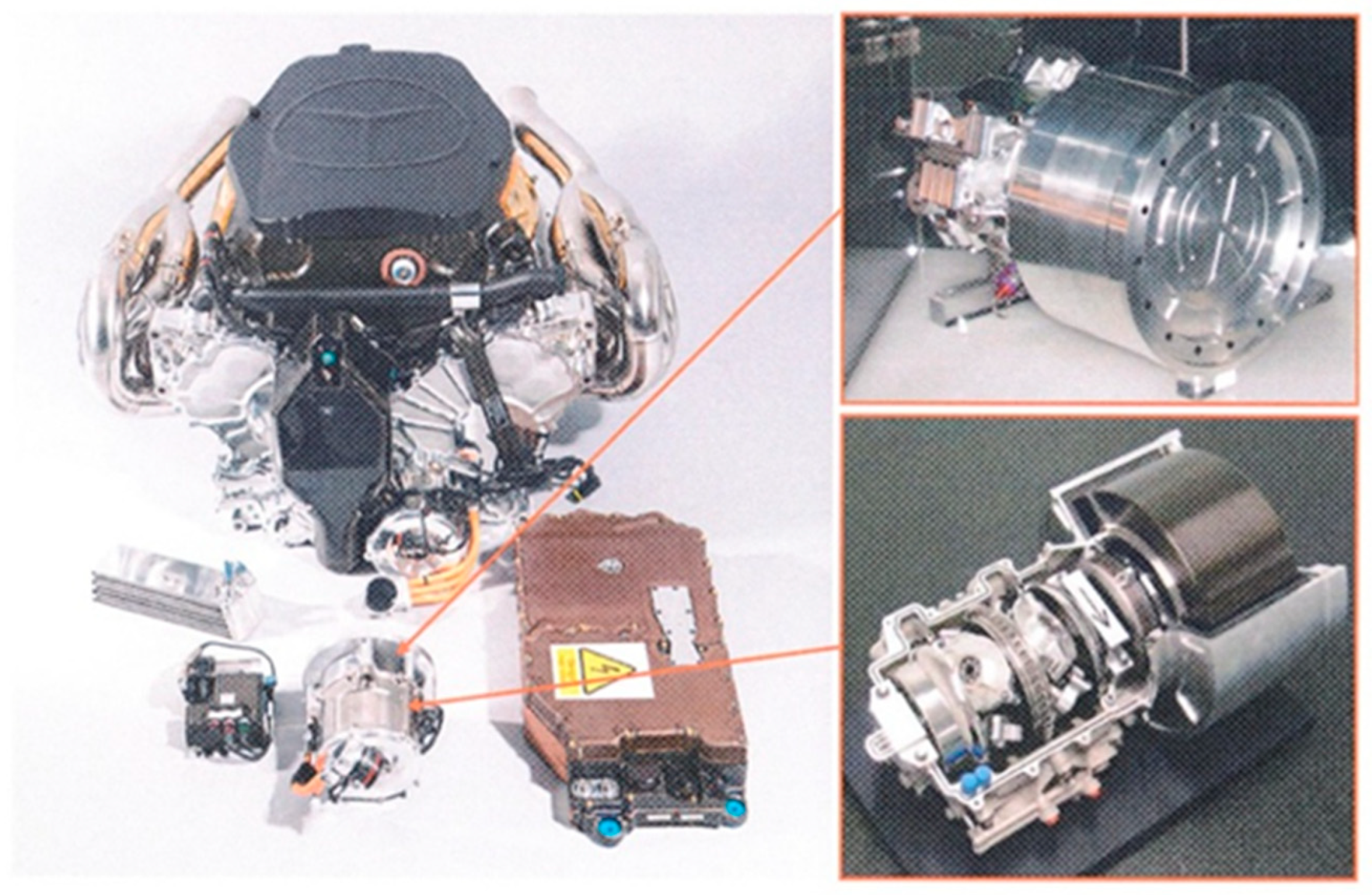
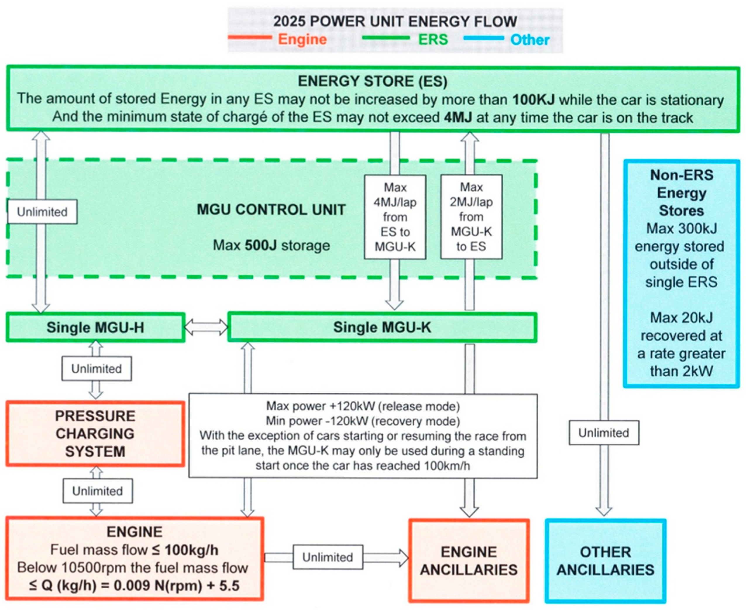
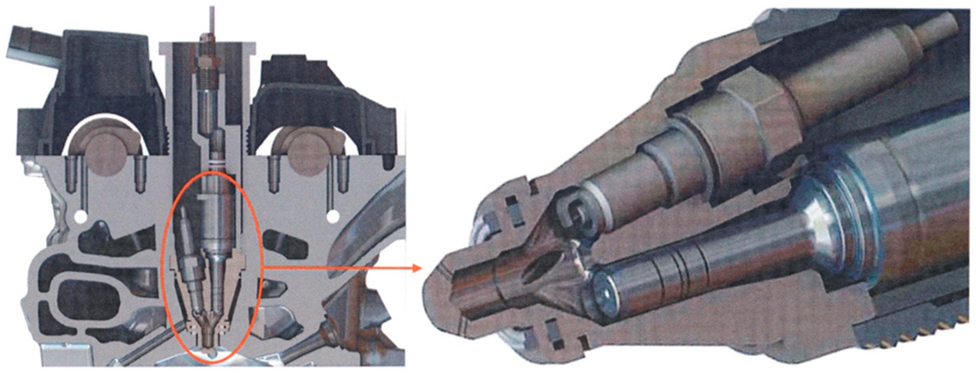
- The 1.6-L, four-stroke, turbocharged V6 gasoline engine, limited to 15,000 rpm, generates approximately 610–625 kW on its own. This small engine is remarkably efficient, generating over 370 kW per liter of displacement. FIA regulations limiting the maximum fuel flow to 100 kg/h (above 10,500 rpm) limit the power output of the internal combustion engine, forcing manufacturers to improve its efficiency, not just increase boost pressure or engine speed. Consequently, Formula 1 engine designers continually optimize fuel consumption through advanced technologies such as Turbulent Jet Ignition (TJI) [18] and direct fuel injection. These advancements increase combustion efficiency and increase engine power (Table 1, Figure 3).
- The Motor Generator Unit-Kinetic (MGU-K) is a brushless AC electric motor with permanent magnets mechanically connected to the engine’s crankshaft, and it plays a key role during vehicle braking. Instead of dissipating kinetic energy as heat, the MGU-K captures it and converts it into electrical energy. This system is used not only to regenerate energy but also to deliver power when it is needed most. In motor mode, the MGU-K can generate 200 Nm of torque and deliver up to 120 kW, while in generator mode, it can conserve up to 2 MJ of battery energy. This means the motor only has enough energy for about 33 s of boost per lap.
- The Motor Generator Unit-Heat (MGU-H) is a brushless, permanent magnet AC electric motor mechanically coupled to the turbocharger. In the MGU-H, exhaust gas entropy (the thermal energy remaining in the exhaust gas as a function of its temperature, expansion, and mass flow rate) is used to rotate the turbine during the energy recovery phase, converting exhaust gas energy into electrical energy. Integrated directly into the turbocharger system, it performs two important functions: it recovers energy as the exhaust gas drives the turbine, and the MGU-H converts this rotational energy into electrical energy. It can also function as an electric motor, turning the turbocharger to eliminate lag and improve engine response (eliminating turbo lag). Unlike the MGU-K, there is no limit to the energy that can be recovered from this MGU. The capacity of both the MGU-K battery and the MGU-H battery is the same, at 2 MJ each. The MGU-H operates continuously, ensuring a constant stream of energy recovery and smoother power delivery. This continuous operation helps maintain the overall efficiency of the drive unit (Figure 3). The MGU-H can operate at speeds up to 125,000 rpm, Figure 3.
- The ERS + Battery and Control Electronics system acts as an intermediary, managing the energy flow between the MGU-K, MGU-H, and the engine. Formula 1 cars use high-capacity battery systems operating at 400 V and with a storage capacity of 4–6 kWh. The lithium-ion battery stores recovered energy and can transfer up to 4 MJ per lap to the MGU-K and accept up to 2 MJ per lap from the MGU-K (from braking). The battery allows the car to release an additional ~120 kW of electrical power over short distances. The battery weighs approximately 25 kg and has an operating temperature of 60–80 °C. Once the boost is activated, energy is replenished through regenerative braking and by the MGU-H, which recycles exhaust gas energy, allowing the cycle to repeat itself lap after lap, Figure 3.
4. Future Hybrid Drivetrains in F1—From 2026 to 2030
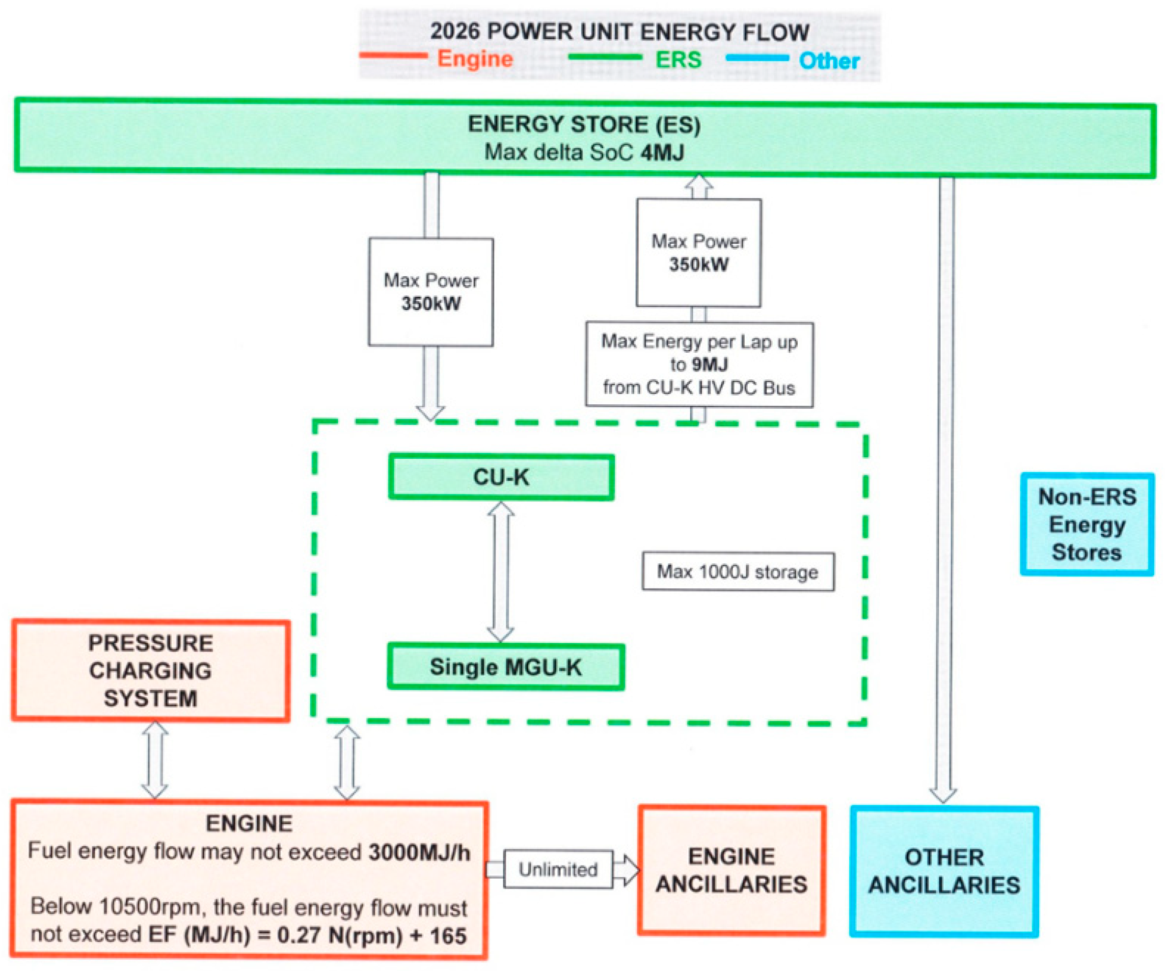
- ICE power will be reduced from the current 550–560 kW to 400 kW (in 2026), i.e., −27%.
- ERS power will be increased from the current 120 kW to 350 kW (in 2026), i.e., +292%. The maximum energy charged to the energy storage (ES) has been increased from 2 MJ to 9 MJ, while the delta state of charge (SoC) limit for the ES remains at 4 MJ.
- Power balance change: the combustion engine to electric power ratio will change from 80/20 (2025) to 53/47 (2026).
5. Fuels for F1 Engines
- ▪
- ▪
- Anti-knock properties. A high octane number allows for high efficiency in spark-ignition (SI) engines. The improved anti-knock properties of high-octane fuels allow for increased ignition timing, leading to a more complete combustion process and thus increased engine efficiency.
- Fuel energy content per mass. Since the fuel mass flow rate is set at 100 kg/h, it is possible to select compounds with higher combustion energy per mass.
- Combustion rate. In the case of a fuel formulation that ensures high flame propagation speed in the combustion chamber, the speed, quality, and completeness of the combustion process are always the main objectives, as these factors directly impact the thermodynamic efficiency of the internal combustion engine.
6. Lubricating Oils for F1 Engines
7. Increasing the F1 ICE Efficiency
- Increasing combustion rate and stability by increasing mixture swirl in the cylinder, increasing fuel atomization pressure in the cylinder, and shaping the jet pattern.
- Improving knock resistance by reducing mixture temperature at the end of cylinder compression and optimizing valve timing.
- Improving combustion efficiency by optimizing the composition and combustion process of a lean mixture and preventing incomplete fuel combustion due to fuel spraying onto the chamber walls caused by improper fuel injection control.
- Optimizing the hydrocarbon composition and fuel additive selection to achieve higher calorific value and increased knock resistance.
- Optimizing the control of fuel atomization in the combustion chamber, combustion mixture formation, and combustion.
8. Conclusions
Funding
Data Availability Statement
Conflicts of Interest
References
- Allen, J. F1 Sponsors and Supporters Drive the Shift to Sustainability. Financial Times, 13 March 2014. [Google Scholar]
- Ornstein, D. Earth Car or not, Button will emit over 50 tonnes of CO2 this season. The Guardian, 2 March 2007. [Google Scholar]
- Ornstein, D. Formula 1 testing in Barcelona, day two as it happened. BBC Sport, 9 March 2011. [Google Scholar]
- Stepien, Z. A new generation of F1 race engines—Hybrid power units. Combust. Engines 2016, 167, 8–23. [Google Scholar] [CrossRef]
- 2009 Formula One Technical Regulations—Fédération Internationale de l’Automobile. Available online: https://argent.fia.com/web/fia-public.nsf/7c4f8d883039af6ac125757d00369c58/$file/1-2009_f1_technical_regulations_showing-alterations_17-03-2009.pdf (accessed on 26 October 2025).
- Mourao, P.R. Smoking Gentlemen—How Formula One Has Controlled CO2 Emissions. Sustainability 2018, 10, 1841. [Google Scholar] [CrossRef]
- Purcell, A. McLaren F1 team goes carbon neutral. New Scientist, 8 December 2011. [Google Scholar]
- Mack, J.; Schuler, D.; Butt, R.; Dibble, R. Experimental investigation of butanol isomer combustion in Homogeneous Charge Compression Ignition (HCCI) engines. Appl. Energy 2016, 165, 612–626. [Google Scholar] [CrossRef]
- Boretti, A. F1 2014: Turbocharged and Downsized Ice and Kers Boost. World J. Model. Simul. 2013, 9, 150–160. [Google Scholar]
- 2014 Formula One Technical Regulations—Fédération Internationale de l’Automobile. Available online: https://argent.fia.com/web/fia-public.nsf/A0425C3A0A7D69C0C12578D3002EBECA/$FILE/2014_F1_TECHNICAL_REGULATIONS_-_Published_on_20.07.pdf (accessed on 26 October 2025).
- Boretti, A. Changes of E-KERS Rules to Make F1 More Relevant to Road Cars. Adv. Technol. Innov. 2018, 3, 26–35. [Google Scholar]
- Boretti, A. Energy flow of a 2018 FIA F1 racing car and proposed changes to the powertrain rules. Nonlinear Eng. 2020, 9, 28–34. [Google Scholar] [CrossRef]
- FIA. 2023 Formula 1 Technical Regulations. Available online: https://www.fia.com/sites/default/files/fia_2023_formula_1_technical_regulations_-_issue_5_-_2023-02-22.pdf (accessed on 25 June 2023).
- McCullough, B.P. Advancing sport ecology research on sport and the natural environment. Sport Manag. Rev. 2023, 26, 813–833. [Google Scholar] [CrossRef]
- Atanasiu, G.; Chiru, A. Internal combustion engine supercharging: Turbocharger vs. pressure wave compressor. Performance comparison. Open Eng. 2014, 4, 110–118. [Google Scholar] [CrossRef]
- FIA. 2026 Formula 1 Power Unit Technical Regulations. Available online: https://www.fia.com/sites/default/files/fia_2026_formula_1_technical_regulations_pu_-_issue_7_-_2024-06-11_1.pdf (accessed on 25 June 2023).
- Schöggl, P.; Grillenberger, D.; Kapus, P. Innovative Motorsport-Powertrains for Sustainable Fuels. In Proceedings of the 46th International Vienna Motor Symposium, Vienna, Austria, 14–16 May 2025. [Google Scholar]
- Qikai, P.; Ruilin, L.; Guangmeng, Z.; Xumin, Z.; Surong, D.; Zhongjie, Z.; Han, Z. Summary of Turbocharging as a Waste Heat Recovery System for a Variable Altitude Internal Combustion Engine. ACS Omega 2023, 8, 27932–27952. [Google Scholar] [CrossRef] [PubMed]
- Shin, A. Comparative Analysis of Traditional Formula 1 Combustion Engines and Modern Hybrid Power Units. Lens J. 2025, 3. [Google Scholar] [CrossRef]
- Sakaida, S.; Furukawa, S.; Ishi, T.; Yokoi, K.; Sato, S.; Tanaka, K.; Konno, M.; Yoneya, N.; Ohata, E. Fundamental study of the mechanism for a gasoline-fueled turbulent jet ignition using an optically accessible prechamber and large-eddy simulation. Therm. Sci. Eng. Prog. 2025, 58, 103228. [Google Scholar] [CrossRef]
- Partridge, J. How a Formula 1 Internal Combustion Engine Works. F1 Chronicle. Available online: https://f1chronicle.com/how-a-formula-1-internal-combustion-engine-works/ (accessed on 30 March 2024).
- Hardy, E. Which Engine Does Each F1 Team Use in 2024? Available online: https://www.autosport.com/f1/news/which-engine-does-each-f1-team-use-in-2024-/10598000/ (accessed on 13 April 2024).
- Scarborough, C. Hybrid F1 Power: How Does It Work? CAR Magazine. Available online: https://www.carmagazine.co.uk/hybrid/how-f1-engine-works/ (accessed on 1 April 2020).
- FIA. 2024 Formula 1 Power Unit Technical Regulations. Available online: https://www.fia.com/sites/default/files/fia_2024_formula_1_technical_regulations_-_issue_3_-_2023-12-06.pdf (accessed on 25 June 2024).
- Warnecke, W.; Poulet, B.; Landschof, J.; Dreyer, A.; Müller-Belau, J.; Lovett, G. Innovation from Track to Road: The Role Fuels can Play in Motorsport. In Proceedings of the 37th Internationales Wiener Motorensymposium, Vienna, Austria, 28–29 April 2016. [Google Scholar]
- Formula 1 Technical Regulations 2026. Available online: https://www.fia.com/sites/default/files/fia_2026_formula_1_technical_regulations_issue_8_-_2024-06-24.pdf (accessed on 26 October 2025).
- Stępień, Z. Synthetic automotive fuels. Combust. Engines 2023, 192, 78–90. [Google Scholar] [CrossRef]
- Hartung, S. Powertrains of the Future—How We Will Meet our Climate Goals through Technology Neutrality. In Proceedings of the 42nd International Vienna Motor Symposium, Virtual, 29–30 April 2021. [Google Scholar]
- Zhu, S.; Akehurst, S.; Lewis, A.; Yuan, H. A review of the pre-chamber ignition system applied on future low-carbon spark ignition engines. Renew. Sustain. Energy Rev. 2022, 154, 111872. [Google Scholar] [CrossRef]
- Xu, J. Thermodynamic evaluation of 2026 Power Unit technical regulation changes in Formula 1. In Proceedings of the 2023 International Conference on Functional Materials and Civil Engineering, Oxford, UK, 26 August 2023. [Google Scholar] [CrossRef]
- Attard, W.; Blaxill, H. A Lean Burn Gasoline Fueled Pre-Chamber Jet Ignition Combustion System Achieving High Efficiency and Low NOx at Part Load; SAE Technical Paper; SAE International: Warrendale, PA, USA, 2012. [Google Scholar] [CrossRef]
- Zhou, L.; Song, Y.; Hua, J.; Liu, F.; Liu, Z.; Wei, H. Effects of different hole structures of pre-chamber with turbulent jet ignition on the flame propagation and lean combustion performance of a single-cylinder engine. Fuel 2022, 308, 121902. [Google Scholar] [CrossRef]
- Hua, J.; Zhou, L.; Gao, Q.; Feng, Z.; Wei, H. Influence of pre-chamber structure and injection parameters on engine performance and combustion characteristics in a turbulent jet ignition (TJI) engine. Fuel 2021, 283, 119236. [Google Scholar] [CrossRef]
- Frasci, E.; Rosa, R.N.; Moreno, B.P.; Arsie, I.; Jannelli, E. Impact of prechamber design and air-fuel ratio on combustion and fuel consumption in a SI engine equipped with a passive TJI. Fuel 2023, 345, 128265. [Google Scholar] [CrossRef]
- Li, G.; Sun, H.; Tang, Q.; Zhen, H.; Wang, H.; Liu, H. Fundamental insights on turbulence characterization, vortex motion and ignition mechanism of sub/ supersonic turbulent jet flames. Appl. Therm. Eng. 2024, 248, 123274. [Google Scholar] [CrossRef]


| Engine | 2009–2013 | 2014–2025 |
|---|---|---|
| Stroke | Not regulated | 53 mm |
| Crank height | Min. 58 mm | 90 mm |
| Number of valves | 4 per cylinder (32) | 4 per cylinder (24) |
| Pressure charging | Normally aspirated | Single turbocharger, unlimited boost pressure (typical maximum 3,5 bar abs due to fuel limit) |
| Max. rpm | 18,000 rpm | 15,000 rpm |
| Max. power | 530–590 kW | 440–630 kW |
| Engine torque | About 350 Nm | 500–600 Nm |
| Fuel injection | Indirect fuel injection | Direct fuel injection |
| Variable intake system | Not allowed | Allowed |
| Compression ratio | 1:12–1:13 | <1:18 |
| Injection pressure | Max. 100 bar | Max. 500 bar |
| Max. fuel flow | Unlimited but typically 150–160 kg/h | Max. 100 kg/h |
| Thermal efficiency | 30–33% | 45–52% |
| Power Unit | 2014–2025 | 2026–2030 |
|---|---|---|
| ICE-Cylinder | V6 90° | V6 90° |
| ICE-Displacement | 1.6 L | 1.6 L |
| ICE-Bore | 80 mm | 80 mm |
| ICE-Stroke | 53 mm | 53 mm |
| ICE-Piston weight | Free | >300 g |
| ICE-Number of valves | 4 per cylinder (24) | 4 per cylinder (24) |
| ICE-Intake valve size | free | 32.5–34.5 mm |
| ICE-Exhaust valve size | free | 27–29 mm |
| ICE-Pressure charging | Single turbocharger, unlimited boost pressure (typical maximum 3.5 bar abs due to fuel limit) | <4.8 bar abs |
| ICE-Max. rpm | 15.000 rpm | 15.000 rpm |
| ICE-Max. power | 440–630 kW | ? |
| ICE-Engine torque | 500–600 Nm | ? |
| ICE-Fuel injection | Direct fuel injection | Direct fuel injection |
| ICE-Variable intake system | Allowed | Not allowed |
| Compression ratio | <1:18 | <1:16 |
| ICE-Injection pressure | Max. 500 bar | Max. 350 bar |
| ICE-Max. fuel flow | Max. 100 kg/h | <3000 MJ/h (70 kg/h) |
| ICE-fuel | 10% biofuel | 100% sustainable |
| MGU-H | Harvest unlimited Energy copped at 2 MJ per lap deployment | Not allowed |
| MGU-K Build | Enclosed with the engine Non-standardized components | Inside chassis with battery in a safety cell Standard component |
| MGU-K Power | 120 kW | 350 kW |
| Max. power | >736 kW | ~736 kW |
| Energy recovery system | MGU-K (Energy recovered from deceleration) MGU-H (Exhaust gas heat turned to Energy) | MGU-K |
| Power breakdown (ICE/Hybrid) | ~80%/~20% ~630 kW/~120 kW | 53%/47% (~390 kW/~350 kW) |
| F1 Fuel Property | 2025 | 2026 | |||
|---|---|---|---|---|---|
| Units | Min | Max | Min | Max | |
| (RON + MON)/2 | 87 | ||||
| RON | 95 | 102 | |||
| Sensitivity (RON-MON) | 15 | ||||
| Density (at 15 °C) | kg/m3 | 720.0 | 785.0 | ||
| Methanol | %v/v | 3.0 | |||
| Oxygen | wt% | 3.45 | 6.70 | 7.10 | |
| Nitrogen | mg/kg | 500 | 500 | ||
| Benzene | wt% | 1 | 1 | ||
| DVPE (Dry vapor pressure equivalent) | kPa | 45 | 68 | 45 | 68 |
| Lead | mg/L | 5 | 5 | ||
| Manganese | mg/L | 2 | 2 | ||
| Metals (excluding alkali metals) | mg/L | 5 | 5 | ||
| Oxidation stability | minutes | 360 | 360 | ||
| sulfur | mg/kg | 10 | 10 | ||
| Electrical conductivity | pS/m | 200 | 200 | ||
| At E70 °C | %v/v | 20.0 | 52.0 | ||
| At E100 °C | %v/v | 40.0 | 80.0 | ||
| At E150 °C | %v/v | 75.0 | |||
| Final Boiling Point | °C | 210 | 210 | ||
| Distillation Residue | %v/v | 2 | |||
| F1 fuel composition | |||||
| Aromatics | wt% | 40 | 40 | ||
| Olefins | wt% | 17 | 17 | ||
| Total diolefins | wt% | 0.1 | 0.1 | ||
| Total styrene and alkyl derivatives | wt% | 0.1 | 0.1 | ||
| Property | Units | Min | Max |
|---|---|---|---|
| Kinematic Viscosity (100 °C) | cSt | 2.8 | |
| HTHS Viscosity at 150 °C and Shear Rate of 106 s−1 | mPa·s | 1.4 | |
| Initial Boiling Point | °C | 210 | |
| Flashpoint | °C | 93 |
Disclaimer/Publisher’s Note: The statements, opinions and data contained in all publications are solely those of the individual author(s) and contributor(s) and not of MDPI and/or the editor(s). MDPI and/or the editor(s) disclaim responsibility for any injury to people or property resulting from any ideas, methods, instructions or products referred to in the content. |
© 2025 by the author. Licensee MDPI, Basel, Switzerland. This article is an open access article distributed under the terms and conditions of the Creative Commons Attribution (CC BY) license (https://creativecommons.org/licenses/by/4.0/).
Share and Cite
Stepien, Z. The Pro-Ecological Evolution of Powertrains and Fuels in Formula 1. Energies 2025, 18, 6013. https://doi.org/10.3390/en18226013
Stepien Z. The Pro-Ecological Evolution of Powertrains and Fuels in Formula 1. Energies. 2025; 18(22):6013. https://doi.org/10.3390/en18226013
Chicago/Turabian StyleStepien, Zbigniew. 2025. "The Pro-Ecological Evolution of Powertrains and Fuels in Formula 1" Energies 18, no. 22: 6013. https://doi.org/10.3390/en18226013
APA StyleStepien, Z. (2025). The Pro-Ecological Evolution of Powertrains and Fuels in Formula 1. Energies, 18(22), 6013. https://doi.org/10.3390/en18226013


