1. Introduction
According to IEEE Standard C57.12.00-D2.1, as the pivotal hub for energy transmission and distribution within power systems, the operational reliability of power transformers directly determines the safety level of the grid [
1]. When a transformer is taken out of service for maintenance or due to a fault, the magnetic hysteresis properties of the core material result in residual magnetism of a certain intensity remaining within the core. This residual magnetism induces an inrush current during reclosing that can reach 6–8 times the rated current. Such inrush currents not only cause mechanical stress accumulation in windings, increasing single-cycle closing stress by up to 25%, and accelerate insulation ageing, reducing service life by approximately 15%, but may also trigger false operation of relay protection devices and even lead to cascading issues such as harmonic pollution of adjacent equipment [
2,
3]. According to the IEEE’s 2023 Power Equipment Failure Statistics Report, approximately 30% of transformer closing faults in power systems are directly attributable to residual magnetism-induced inrush currents. The annual losses from grid outages and equipment maintenance costs exceeding hundreds of millions of US dollars stem from this phenomenon [
4]. Consequently, the ability of residual magnetism detection devices to accurately assess the residual magnetism state of transformer cores represents a critical technological element in suppressing inrush currents and ensuring stable grid operation.
In recent years, residual magnetism detection techniques have encompassed empirical estimation methods, voltage integration methods, pre-magnetisation methods, and AC/DC indirect detection methods [
5,
6]. Many measurement methods fundamentally exploit the principle that magnetic permeability varies with residual magnetism, leading to inconsistent self-inductance or mutual inductance coefficients in windings. Residual magnetism in the core is calculated by measuring the coil’s response to different voltage signals. However, changes in transformer coil inductance are influenced not only by residual magnetism and environmental factors but also significantly by the previous inflection point of the hysteresis loop. Consequently, residual magnetism detection methods such as frequency response analysis and small hysteresis loop integration are equally influenced by coil inductance values. This paper, therefore, proposes a precision magnetisation platform for transformers featuring dynamically adjustable inductance. This enables verification of residual magnetism detection methods under inductance disturbance conditions and calibration of residual magnetism detection apparatus accuracy.
In the study of transformer magnetic characteristics, the hysteresis phenomenon constitutes an inherent property of ferromagnetic materials. An accurate description of transformer hysteresis characteristics is a prerequisite for researching precise magnetisation and dynamic inductance adjustment strategies. To date, researchers have proposed multiple hysteresis models. Among these, the Preisach hysteresis model has found extensive application in transformer magnetic characteristic analysis [
7,
8,
9] due to its ability to effectively reflect the hysteresis loop shape and hysteresis losses of ferromagnetic materials. The Preisach model describes overall hysteresis characteristics through the superposition of a series of basic hysteresis units possessing rectangular hysteresis loops, employing distribution functions to characterise the distribution of these basic units. However, this model suffers from computational complexity and insufficient accuracy in parameter identification, limiting its further application in engineering practice [
10,
11].
In recent years, artificial intelligence techniques have delivered crucial breakthroughs for the engineering application of the Preisach hysteresis model. Addressing computational redundancy issues in the Preisach model, reference [
12] proposed an approximate scheme using particle swarm optimisation to train feedforward neural networks, enhancing both predictive accuracy and training efficiency to enable real-time hysteresis analysis. By integrating the classical Preisach model with machine learning, a non-parametric high-fidelity model was constructed and successfully applied to characterise and optimise the hysteresis system of a particle accelerator [
13]. Neural operator architectures further extend model generalisation capabilities. By fitting the Preisach distribution function via Fourier neural operators, precise prediction of untrained hysteresis loops is achieved [
14]. Dynamic parameter identification methods based on uncertain neural network systems reduce the Preisach model’s reliance on historical data [
15], whilst hybrid neural network-Preisach operator fusion models achieve a 40% reduction in inverse compensation errors [
16].
Prior to precise magnetisation, the calibration platform must first demagnetise the transformer. Commonly employed demagnetisation methods include direct current demagnetisation, alternating current demagnetisation, and pulse demagnetisation [
17,
18]. The DC demagnetisation method achieves demagnetisation by applying a gradually decreasing direct current, but the demagnetisation effect is significantly influenced by the rate of current change, with errors exceeding ±10% [
19]. The AC demagnetisation method reduces the amplitude of the alternating voltage to achieve demagnetisation, offering relatively simple operation but taking over 30 min [
20]. The pulse demagnetisation method utilises the magnetic field generated by pulsed currents for demagnetisation, demonstrating high efficiency but demanding higher equipment specifications [
21]. In the magnetisation scheme, the transformer core is primarily subjected to a specific magnetic field to impart a predetermined residual magnetism. However, the standard value of the generated residual magnetism fluctuates by more than ±5%, rendering calibration consistency unattainable [
22].
Accurate calculation of transformer inductance values is a prerequisite for dynamic inductance adjustment. Currently, the primary methods for calculating transformer inductance include analytical methods, numerical analysis techniques, and experimental measurement approaches [
23,
24]. Analytical methods derive inductance formulas based on electromagnetic theory, offering rapid computation but exhibiting lower precision due to the omission of certain complex factors; Numerical analysis methods, such as the finite element method, can account for the complex structure and material properties of transformers, offering higher computational accuracy. However, the calculation process is intricate and time-consuming. Experimental measurement methods can directly obtain inductance values but are subject to the limitations of experimental equipment and measurement environments, making it difficult to guarantee the accuracy and repeatability of the results [
25,
26,
27]. Integrating the advantages of these various methods to achieve accurate and reliable dynamic adjustment of inductance values represents one of the key challenges currently requiring resolution in the field of transformer parameter research.
In summary, although scholars both domestically and internationally have achieved certain research outcomes in areas such as transformer hysteresis models, residual magnetism control, and inductance calculation, numerous shortcomings persist in the generation strategies for standard parameters within residual magnetism detection device calibration platforms. For instance, existing hysteresis models struggle to meet engineering practice demands in terms of precision and efficiency; the accuracy and stability of residual magnetism standard value generation require further enhancement; and methods for generating inductance standard values lack uniformity and standardisation. Therefore, conducting research on precise magnetisation and dynamic inductance adjustment strategies, and establishing a comprehensive and reliable standard parameter generation system, holds significant practical importance for advancing power transformer technology and ensuring the safe and stable operation of power systems.
To this end, this paper investigates strategies for generating standard parameters for residual magnetism detection and calibration platforms in power transformers, with the following core contributions: (1) Optimisation of the Preisach hysteresis model: Deriving parameter expressions through analytical methods and incorporating the Everett integral distribution function to provide a high-precision foundation for magnetic characteristic analysis; (2) Proposal of a standardised residual magnetism generation process: First, rapid decaying AC demagnetisation with 20 half-cycle reductions; subsequently, precise residual magnetism control during magnetisation achieved through combined positive/negative saturation excitation and fine-tuning with reverse micro-pulse currents, maintaining residual magnetism standard values within ±6% accuracy; (3) Establishing a dynamic inductance adjustment mechanism: Integrating hysteresis loop characteristics, proposing a quadratic polynomial fitting method for excitation current peaks and normalised inductance to unify adjustment standards. Finally, an experimental platform was constructed to validate the effectiveness and feasibility of the proposed standard parameter generation strategy for the residual magnetism detection device calibration platform of power transformers.
2. Transformer Hysteresis Model
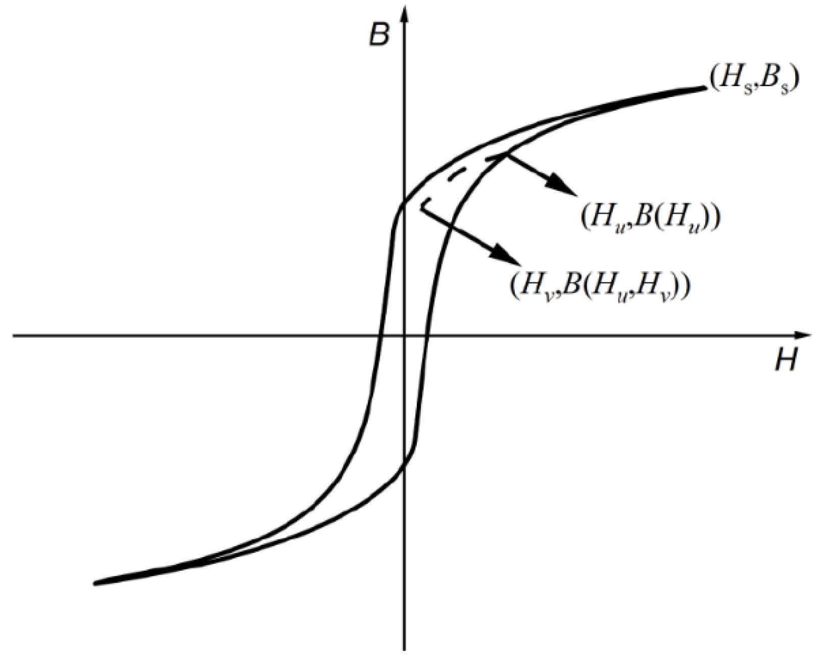
The accuracy of the model parameters directly determines whether the model can accurately simulate the hysteresis characteristics of ferromagnetic materials. The analytical formula method is used to calculate the parameters of the Preisach hysteresis model, and the Everett integral distribution function E(H
u,H
v) = 1/2[B(H
u,H
v) − B(H
u)] is introduced. As shown in
Figure 1, B(H
u) is the magnetic flux density output value of the limiting hysteresis loop when the input is Hu, and B(H
u, H
v) is the turning point on the limiting hysteresis loop, which is the magnetic flux density output value when the input decreases to Hv obtained from the first-order reversal curve.
The output of the initial magnetization curve, the descending branch, and the ascending branch of the hysteresis loop for this model is expressed as
By characterizing the Preisach distribution function with an analytical function, the forward model can be obtained:
where
represents the reversible component of the magnetization,
represents the irreversible component at the turning point of the hysteresis curve,
n is the number of terms of the Everett function,
,
,
,
,
,
,
,
,
,
,
,
k2, and
k3 are the parameters of the model.
Differentiating the magnetic flux density output
B(
t) with respect to the magnetic field strength gives
where
. Based on the numerically discretized approximate difference expression of
dB(
t)
/dH(
t):
, the magnetic field strength at the next time step can be obtained:
Rearranged, the magnetic field strength is
Based on this model, the parameters of the model can be fitted according to the initial residual flux value of the core and the state of the curve after zero-flux control as the starting point, based on the changes in magnetic flux density and magnetization intensity.
3. Principles Governing the Generation of Standard Residual Magnetism Values for Transformers
The generation of residual magnetism standard values for transformers necessitates a controllable and repeatable magnetisation process, with the core procedure being ‘demagnetisation followed by magnetisation’. This sequence stems from the unique magnetic properties of transformer cores, whose residual magnetism exhibits significant historical dependency. The residual magnetism is cumulatively influenced by prior magnetisation operations, such as transportation, installation, and trial runs. If magnetisation is applied directly, the original residual magnetism would combine with the new magnetisation effect. This would result in a final residual magnetism value exhibiting high dispersion and poor stability, rendering it unsuitable as a standard reference value. Therefore, it is necessary to first demagnetise the core to eliminate residual magnetism, returning it to a magnetically neutral initial state. Subsequently, controlled magnetisation conditions are applied based on a specific magnetisation protocol. This approach generates a residual magnetism standard value characterised by consistency and repeatability.
3.1. Demagnetization Scheme
Using silicon steel sheets as an example,
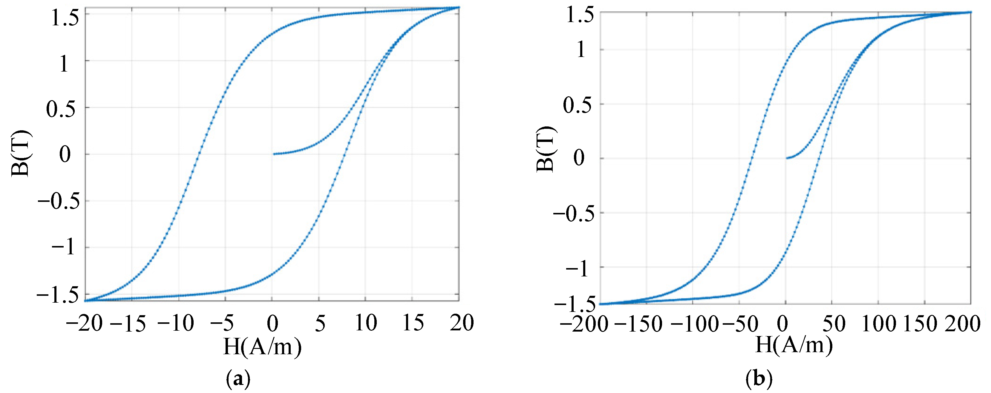
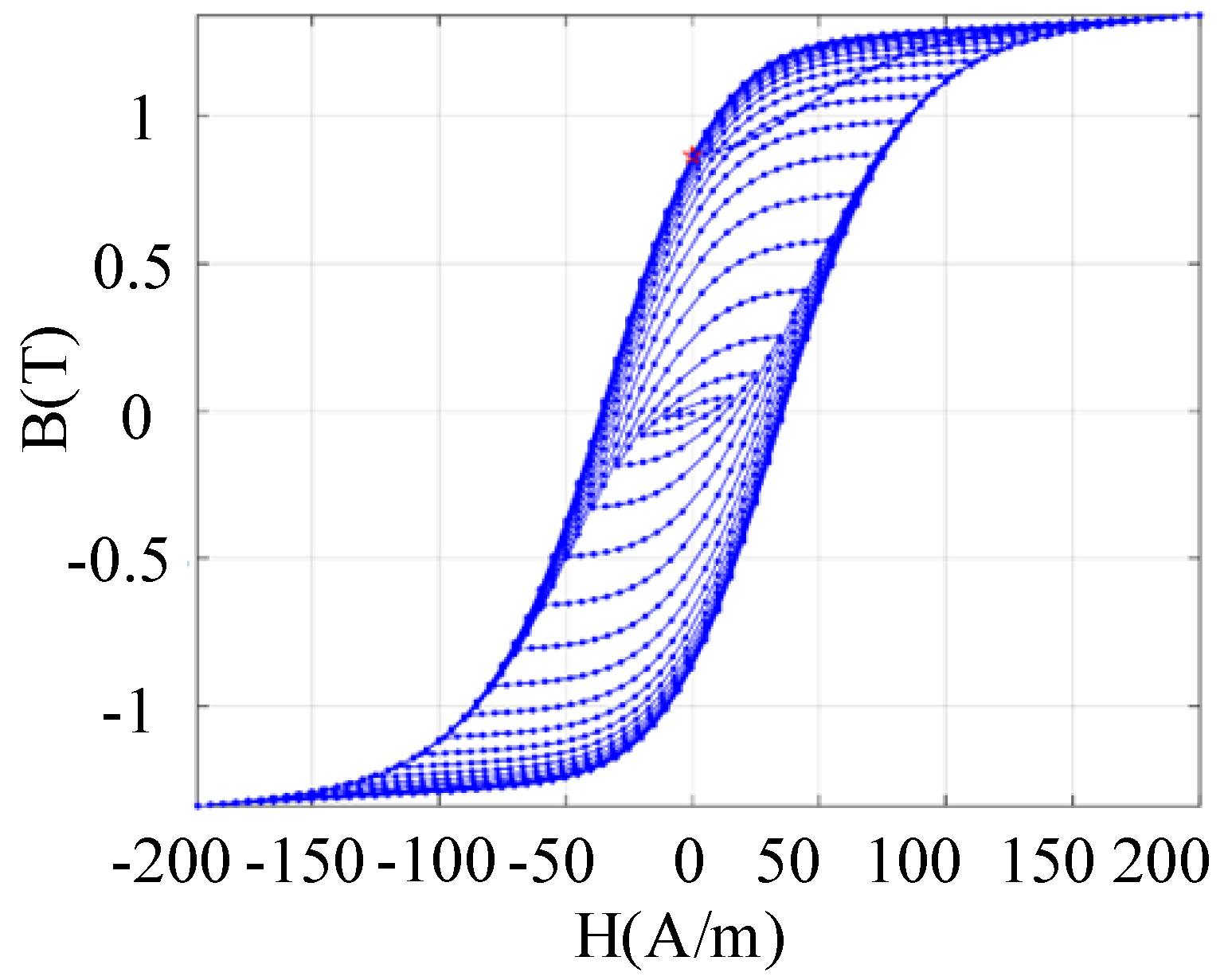
Figure 2 depicts hysteresis loops for both grain-oriented and non-grain-oriented types based on the Preisach model, showing distinct characteristics. Applying an alternating current with decreasing amplitude to reduce magnetic flux density produces BH curves shown in
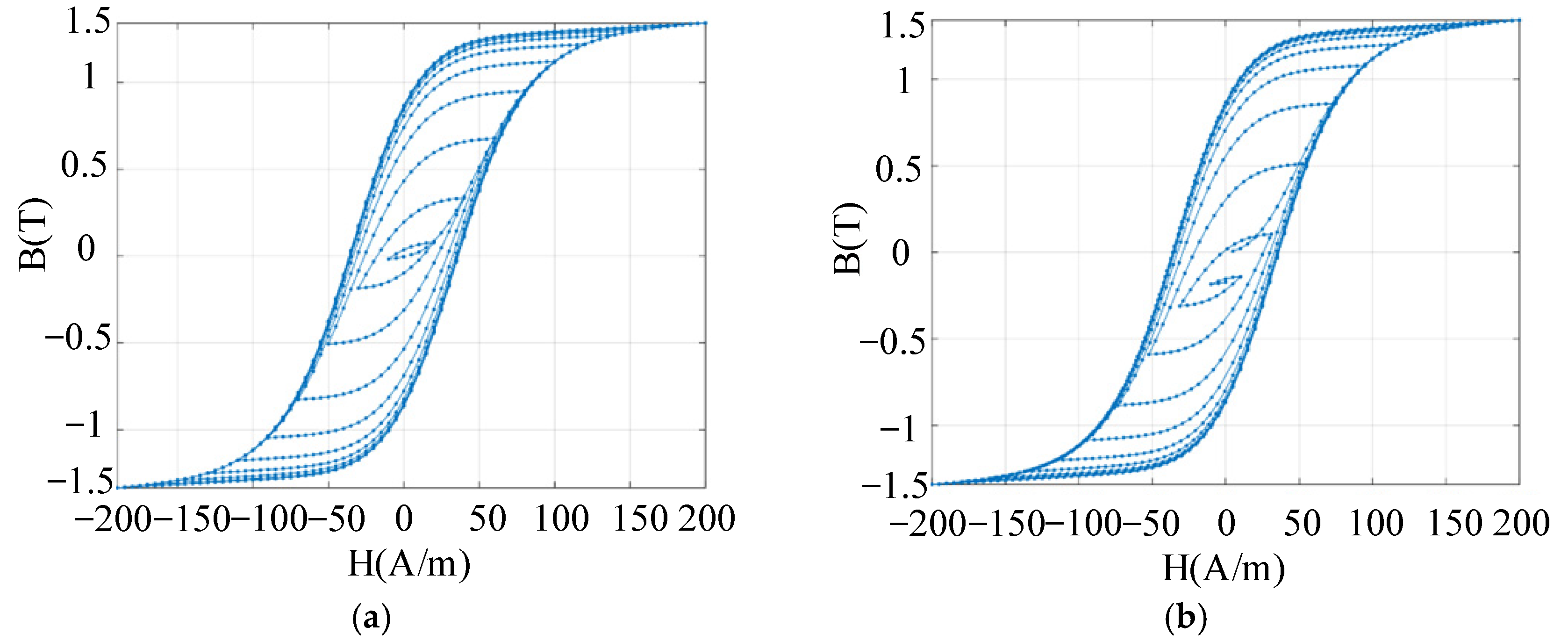
Figure 3. The method of decreasing AC amplitude influences core residual magnetism. Reducing the amplitude in full-cycle increments results in greater residual magnetism than half-cycle increments. We verified whether this characteristic also applies to core demagnetisation.
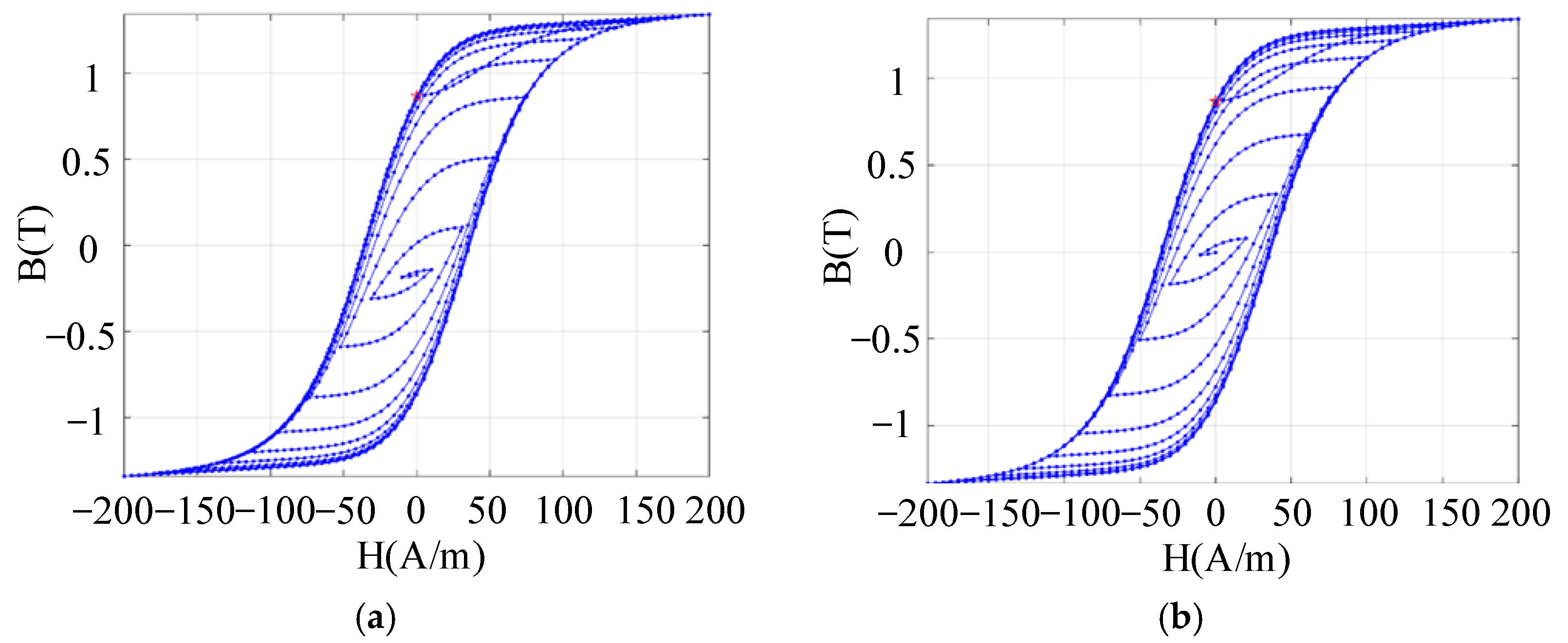
Set a fixed residual magnetism, with the asterisk marking the residual magnetism of the silicon steel sheet.
Figure 4 illustrates the demagnetisation effect of excitation alternating current amplitude at different decay time scales. After ten decay cycles, the demagnetisation effect achieved by decreasing excitation in half-cycle increments significantly outperforms that achieved in full-cycle increments.
Figure 5 depicts the demagnetisation effect after increasing the decay rate of the excitation current amplitude. The decay process is completed over 20 cycles. Compared to
Figure 4a, the demagnetisation effect is significantly improved when the decay rate of the excitation current amplitude is higher.
Therefore, for silicon steel sheet cores, demagnetisation may be achieved using an alternating current with decaying amplitude. Specifically, the excitation current amplitude is reduced in half-cycle increments while simultaneously increasing the decay rate (for instance, completing the entire process through 20 successive decay cycles). Moreover, while the energy consumption of this 20-half-cycle demagnetisation process is relatively low, it necessitates the generation of substantial instantaneous currents. This requirement relies on high-power components for implementation, resulting in elevated costs. This constitutes the primary limitation hindering its practical application.
3.2. Magnetization Scheme
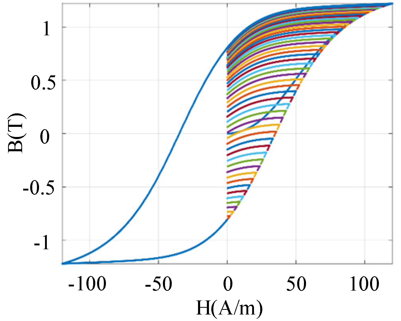
As the hysteresis loop reflects the state and variation prior to magnetisation, it is essential to analyse hysteresis curves and remanence under different magnetisation processes. As shown in
Figure 6, after saturation excitation, varying the final excitation current amplitude leads to distinct hysteresis curves and core remanence values. Therefore, during magnetisation, the excitation current can first be increased to the reverse saturation region. Then, based on the corresponding relationship, the forward current can be raised to its corresponding peak value. Finally, reducing the current yields the desired remanence. However, the accuracy of this open-loop magnetisation is susceptible to factors such as temperature. If the residual magnetism from the initial magnetisation does not meet the required accuracy, reverse magnetisation to the reverse saturation region can be applied. Subsequently, the peak forward magnetising current should be readjusted and reduced to ensure the residual magnetism is slightly above or below the original value. Nevertheless, this fine-tuning method requires magnetising to the reverse saturation region first, leading to extended magnetisation times and increased power consumption. The following section explores whether residual magnetism can be finely adjusted using small forward or reverse excitation currents based on the existing residual magnetism.
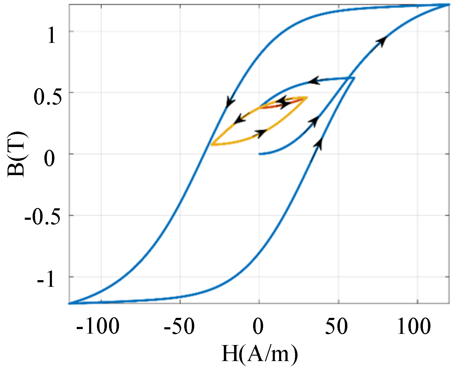
Figure 7 shows the hysteresis loop under an excitation current with the same polarity as the previous one, in the presence of residual magnetism. It can be seen that after half a cycle, the residual magnetism equals its initial value. After each full cycle, the core’s residual magnetism returns to its initial state. Therefore, using a small excitation current of the same polarity cannot fine-tune the residual magnetism. As shown in
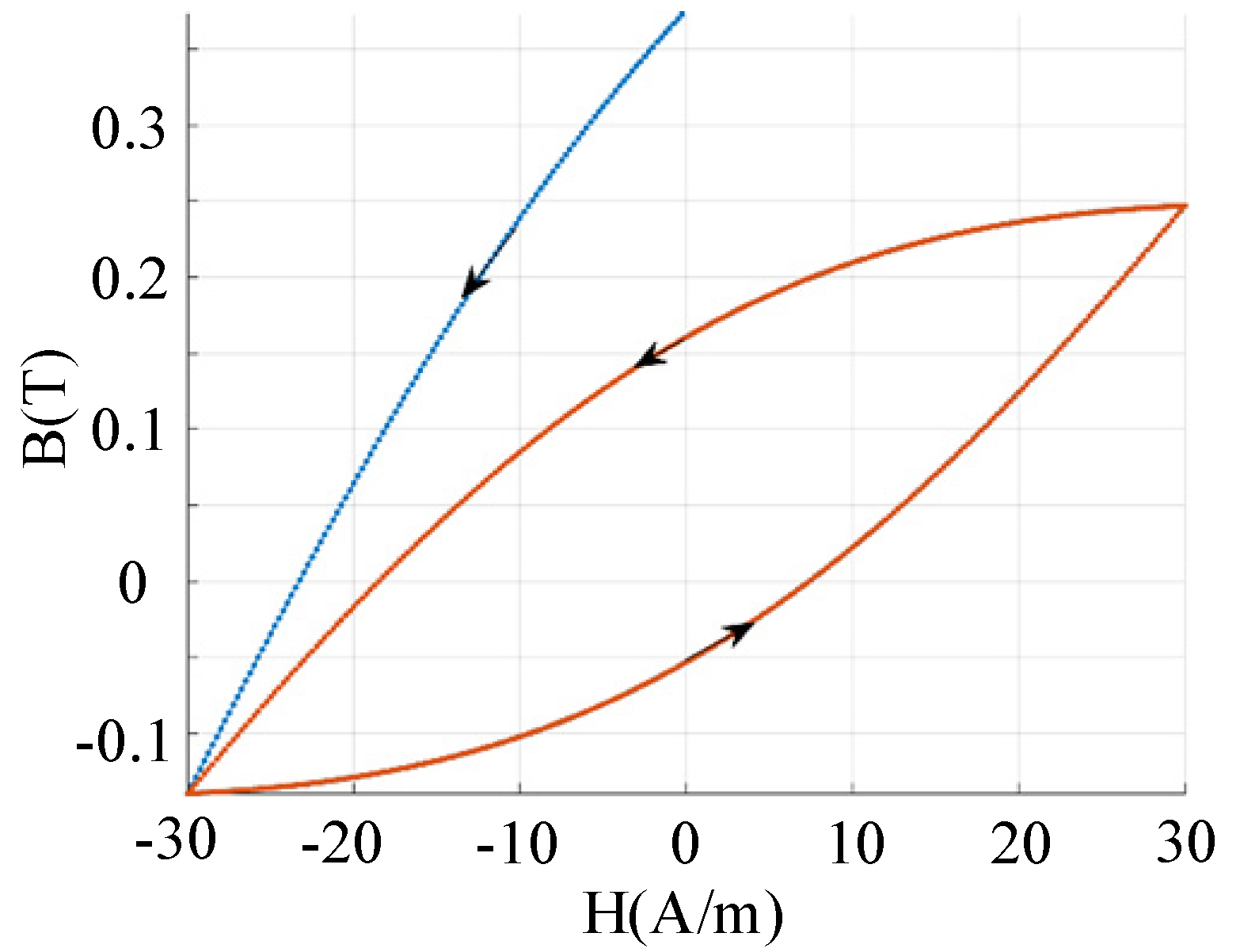
Figure 8, when a small opposite-polarity excitation current is applied, the entire hysteresis loop shifts downward, clearly indicating a change in remanence. Since the direction of the previous current is known during magnetisation, subsequent excitation currents and directions can be selected based on the deviation between the current and target remanence to achieve fine adjustment.
Based on the analysis of the aforementioned hysteresis loop characteristics, the following appropriate magnetisation strategy can be derived. First, magnetise the core along the large hysteresis loop using positive and negative saturation excitation currents to achieve the desired residual magnetism. Subsequently, fine-tune the residual magnetism using small pulse currents in the opposite direction to the final excitation current. This enables precise control of the transformer’s residual magnetism.
4. Principle of Dynamic Inductance Adjustment for Transformers
To assess whether the output values of the residual magnetism detection device are affected by different transformer inductance values, precise dynamic adjustment of the transformer winding inductance must be achieved. According to the electromagnetic induction formula, the induced electromotive force in the winding can be calculated using the following equation:
where
N denotes coil turns,
ϕ the magnetic flux,
L the inductance, and
i the coil current. The coil current and the core’s magnetic field strength satisfy
l is the magnetic path length. The magnetic flux can be calculated by:
Substituting Equations (7) and (8) into Equation (6) gives
Assuming the change in magnetic flux density is very small and extremely slow, and neglecting the change in the inductance value, we get
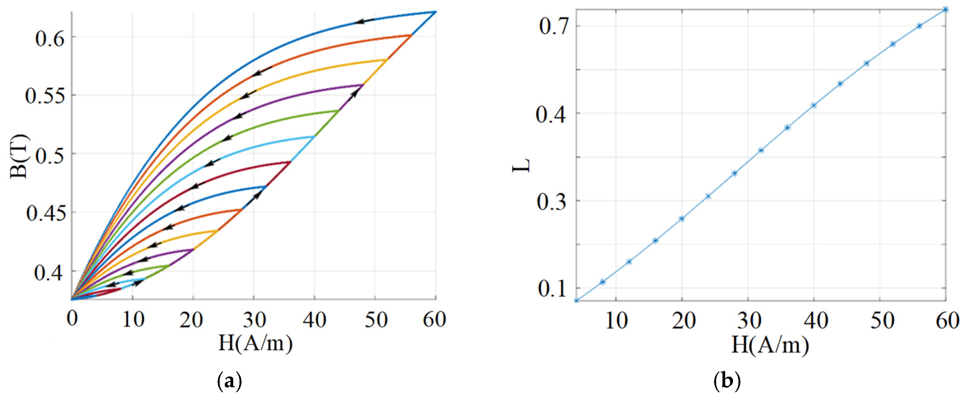
Figure 9a shows hysteresis loops in silicon steel with 0.37 T residual magnetism after excitation at different peak currents in the final current direction.
Figure 9b presents corresponding inductances calculated with Equation (10). Residual magnetism remains unchanged, yet inductance varies: higher peak currents yield greater inductance after excitation. The standard procedure for power transformer parameters is thus: demagnetisation first, then magnetisation, and finally inductance customisation. For computational ease, after the final magnetising current, the relationship between in-phase excitation current peaks and normalised inductance can be represented by a quadratic polynomial. For example,
Figure 10 shows normalised inductance values fitted using Equation (11), closely matching actual measurements.
5. Experimental Results
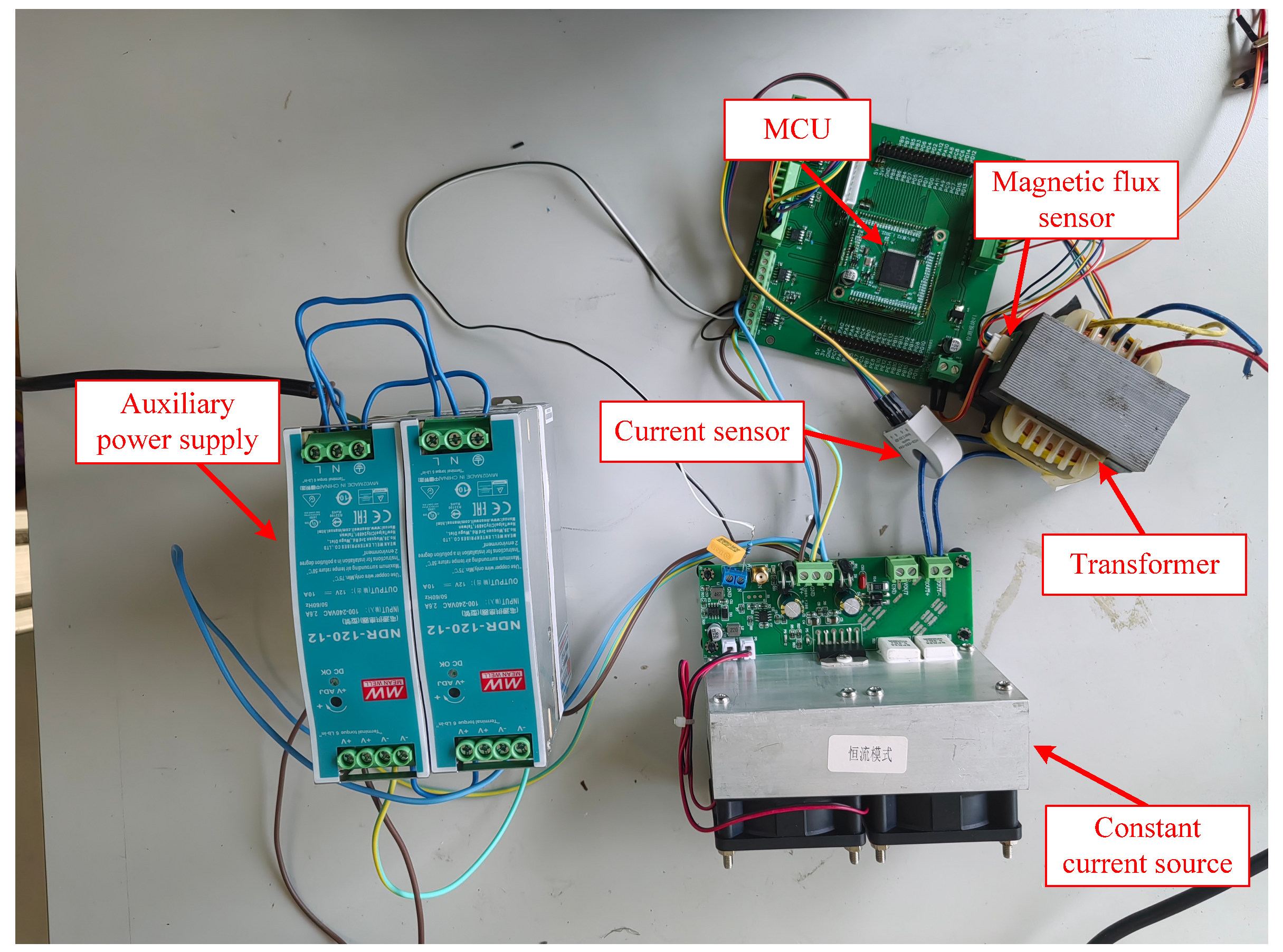
To validate the effectiveness of the proposed standard parameter generation strategy, a verification platform experimental prototype was constructed, as shown in
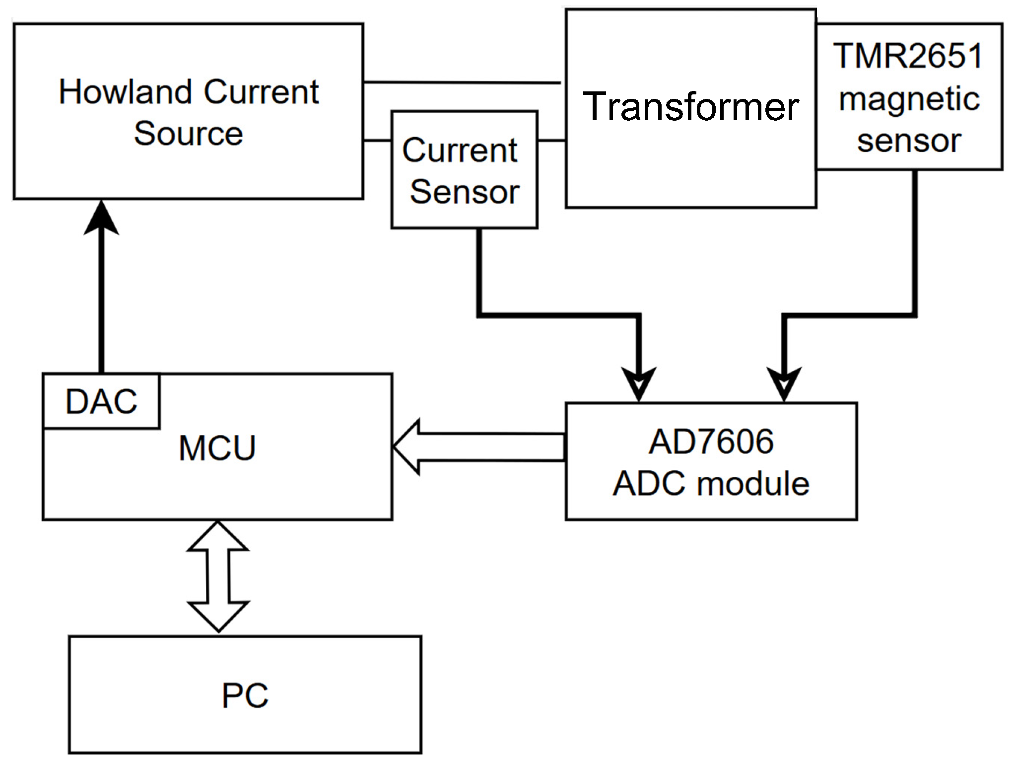
Figure 11. The system hardware architecture block diagram is shown in
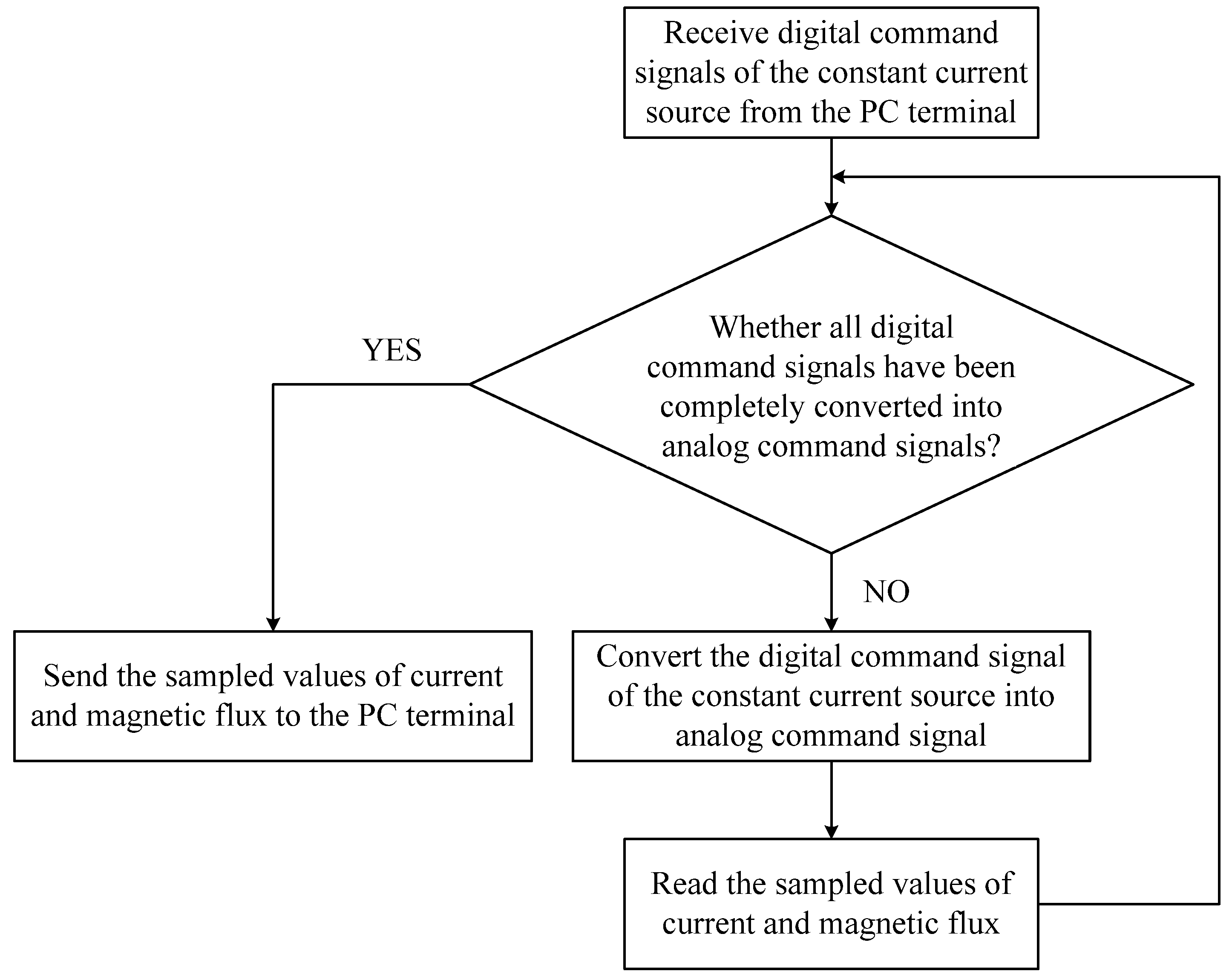
Figure 12, and the MCU task flowchart is shown in
Figure 13. The main component models are listed in
Table 1. The flux sensor error is less than 2.23 Gs. The current sensor error is less than 5 mA. Silicon steel sheets were selected as the core material for the transformer. A constant current source generated by a power operational amplifier was used as the excitation current. A magnetic flux sensor was attached to the side of the transformer. The excitation current in the primary winding was detected using a Hall current sensor. The PC plotted the BH curve based on the measured magnetic flux density and magnetic field strength, and the dynamic inductance was calculated according to Equation (9). All test values were normalized: the residual flux test values were normalized using the reciprocal of the maximum residual flux under saturated current, while the dynamic inductance test values were normalized using the reciprocal of the inductance value under saturated current.
Table 2 presents the demagnetization results, showing that after 20 rapid decays of the sinusoidal excitation current, the residual flux in the core was essentially reduced to zero.
Table 3 shows the magnetization accuracy test results, indicating a relative magnetization precision within 6%. When the residual flux was fixed at a specific value, the adjustment accuracy of the dynamic inductance is summarized in
Table 4. The relative error exhibited fluctuations, with a maximum error of approximately 20% and a minimum error of only 2%. The primary cause of errors reaching up to 20% in dynamic inductance control for transformers likely stems from the dynamic inductance model’s omission of core hysteresis losses, eddy current effects, and the non-linear variation in magnetic permeability with current and frequency during its establishment. Concurrently, hardware-level issues such as insufficient sensor accuracy and control algorithm response delays contribute to the discrepancy. Furthermore, uncontrolled environmental factors like temperature and humidity during experimentation further exacerbate the deviation between actual values and the ideal control target.
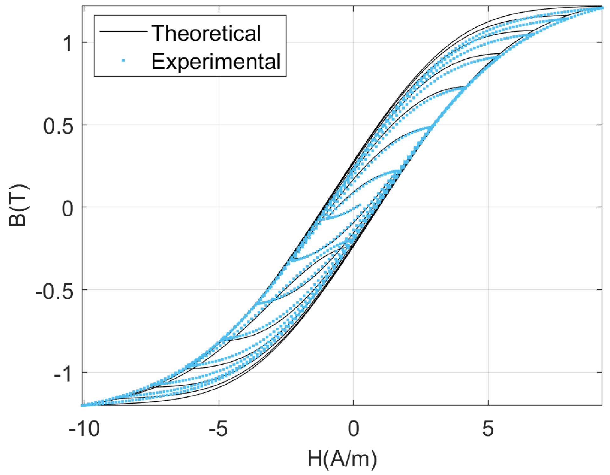
Figure 14 presents a comparison of the theoretical BH curve derived using the Preisach hysteresis model during demagnetisation with the experimental BH curve. It can be observed that the theoretical and experimental curves are in close agreement.
