1. Introduction
New energy industries such as photovoltaic power generation play a crucial role in addressing energy shortages and environmental pollution, holding significant importance for national power and energy development [
1]. Grid-connected inverters serve as the critical interface between distributed power sources and the grid, with their performance directly impacting power quality and system stability. LCL filters are widely adopted as output filters for grid-connected inverters due to their exceptional high-frequency harmonic attenuation capability within a compact inductive volume, serving as a vital tool for power quality control [
2].
However, as a third-order passive system, the LCL filter exhibits an inherent resonance peak at its resonant frequency. This inherently high-amplitude resonance spike may cause system instability [
3]. To address resonance issues, passive damping (PD) methods were initially widely adopted [
4], involving the series or parallel connection of physical resistors in the filter capacitor or inductor branches [
5]. Although this approach is simple to design and highly reliable, the introduction of resistors causes additional power losses, reducing overall system efficiency—particularly during rated power operation—which contradicts the fundamental requirement for efficient operation in renewable energy systems [
6]. Furthermore, damping resistors also affect the filter’s high-frequency attenuation characteristics and suffer from issues such as heat generation and aging [
7].
In recent years, active damping (AD) technology has emerged as a solution to the inherent limitations of passive damping and has become a research hotspot [
8]. Capacitive current feedback active damping, in particular, has gained widespread application due to its advantages in terms of simple engineering implementation, minimal energy dissipation, and preservation of low-frequency gain without affecting filtering [
9]. Active damping strategies based on state observers [
10] or advanced multivariable control methods [
11] have also been applied to resonance suppression, further enhancing system robustness and dynamic response performance. Furthermore, techniques such as quasi-proportional resonance controllers [
12] and repetitive control [
13] can effectively suppress specific subharmonics and enhance the quality of grid-injected current.
In practical engineering applications, however, particularly in ‘weak grid’ scenarios involving long-distance transmission, the background impedance of the power grid cannot be ignored. Grid impedance interacts with LCL filters, altering the system’s original resonant characteristics. This can degrade the performance of controllers designed based on rated parameters and may even trigger stability issues [
14]. Furthermore, background voltage harmonics (such as the 5th and 7th harmonics) present in the grid can enter the system through common coupling points. This causes distortion in the grid-connected current, making it difficult to meet grid connection standards [
15]. To suppress grid voltage disturbances, traditional approaches typically use full feed-forward techniques for grid voltage. While this method effectively reduces steady-state error, the positive feedback effect it introduces significantly diminishes phase margin under weak grid conditions. When grid reactance is high, this can easily trigger system instability [
16]. To enhance the robustness of the feedforward loop, Reference [
17] proposes a virtual impedance-based feedforward control strategy that improves system stability to some extent, although the design process is relatively complex. Reference [
18] employs a second-order differential phase-differential term of the grid-connected current as feedforward to suppress the filter’s intrinsic resonant frequency. While this approach provides superior system stability and resistance to interference, it is significantly impacted by noise.
Traditional proportional–integral controllers are widely used in current-loop controller design for three-phase systems due to their ability to achieve dead-heavy tracking of DC signals in synchronous rotating coordinates [
7]. However, their performance is limited in single-phase systems or for specific harmonic suppression. Proportional-resonant controllers can provide infinite gain at specific frequencies (e.g., the fundamental frequency) in stationary coordinates, enabling dead-heavy tracking of AC signals at that frequency [
19]. Nevertheless, ideal PR controllers are sensitive to grid frequency deviations and struggle to suppress specific harmonics [
20]. To address this issue, quasi-proportional resonance controllers and multi-resonance controllers have been proposed. By incorporating resonance terms at multiple frequency points (e.g., the fundamental frequency and the 5th and 7th harmonics), these controllers can effectively suppress multiple specific harmonics, significantly improving grid-connected current quality [
21]. However, the performance of quasi-proportional resonators and multi-resonance controllers still depends heavily on accurate tracking of the power grid frequency. Furthermore, when the power grid frequency fluctuates or background harmonic interference occurs, setting the parameters for multiple resonance peaks becomes more complicated [
22].
Based on the above analysis, significant progress has been made in existing research on resonance damping, grid disturbance feedforward compensation and harmonic suppression for LCL grid-connected inverters. However, challenges remain. Firstly, most strategies address individual issues (e.g., damping resonance or suppressing harmonics) in isolation, rather than using a composite control scheme that can address resonance stability, grid impedance disturbances and multi-frequency harmonic problems simultaneously. Secondly, while some complex control strategies (e.g., fully adaptive control) are highly robust, they rely on precise sensors and complex online algorithms, which limits their engineering applicability. For example, Reference [
23] uses an adaptive improved feedforward strategy that adjusts the feedforward policy dynamically based on grid impedance variations. While this improves the robustness of the grid-connected system, it necessitates extensive state estimation and a large number of high-precision sensors, resulting in significant costs. Finally, balancing simplicity, cost-effectiveness and high system performance remains a critical optimisation challenge.
To address grid distortion and system instability caused by grid impedance and voltage harmonics in weak grids, this paper proposes a composite control strategy. Its core innovations are: First, an improved resonant feedforward control is introduced. By incorporating a resonant element into the feedforward channel, it actively counteracts the negative effects of grid impedance. This approach maintains the system’s high-frequency open-loop gain and reduces steady-state error while significantly enhancing stability margins. Second, replacing the traditional PI controller with a quasi-proportional resonant and harmonic compensator. This design achieves both efficient active damping and excellent specific harmonic suppression capability without requiring additional sensors, effectively improving grid-connected current quality and reducing system costs. Through Matlab/Simulink simulations, the proposed strategy demonstrates excellent stability and superior dynamic performance.
2. LCL Grid-Connected Inverter Mathematical Model
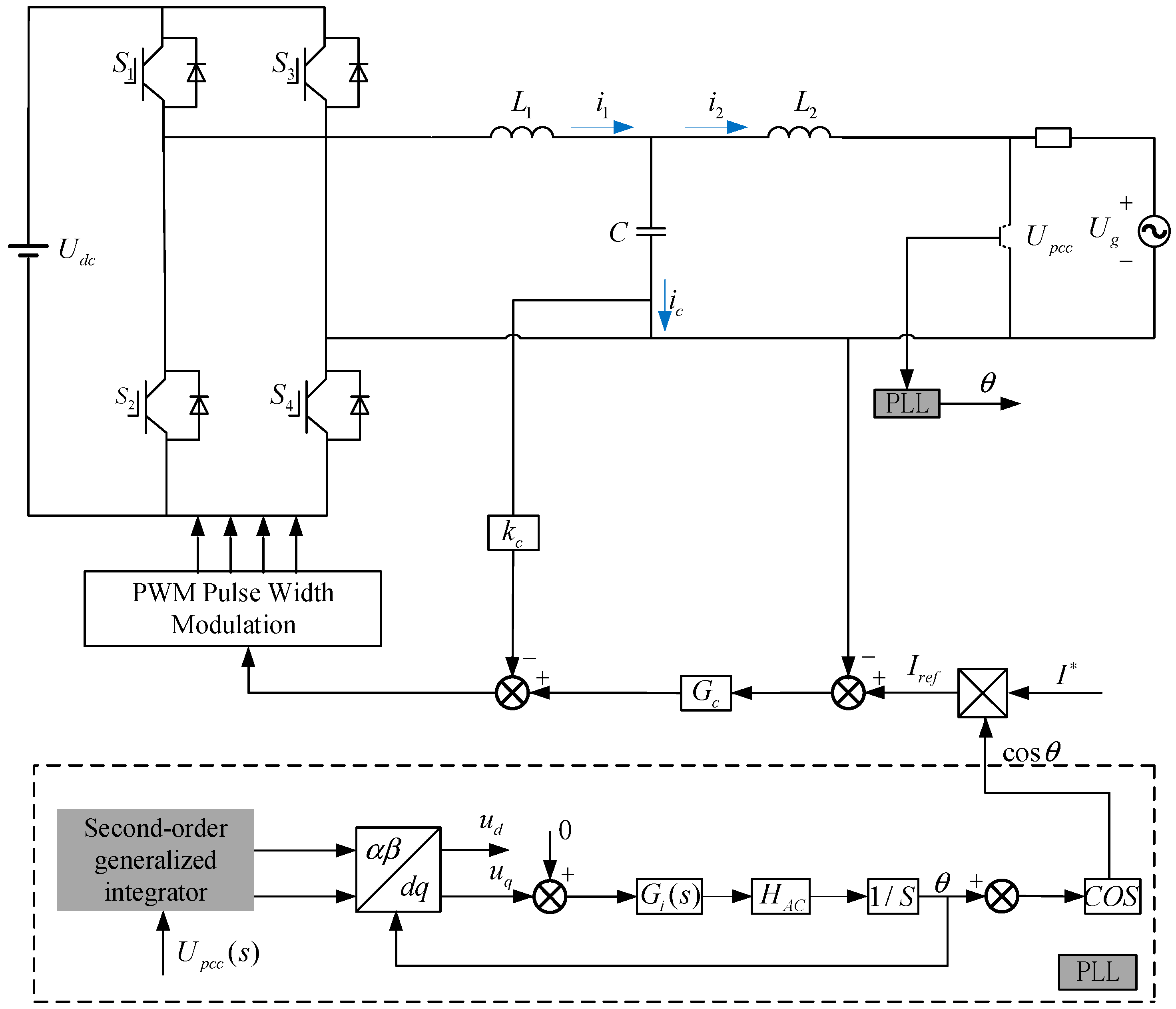
Figure 1 shows the main circuit and control schematic of a single-phase voltage-type grid-connected inverter. The main circuit comprises an inverter full-bridge circuit formed by four switching devices.
represents the DC-side input voltage. The inverter-side inductor
, filter capacitor C, and grid-side inductor
collectively form an LCL filter.
denotes the grid voltage, and
represents the grid impedance. The control section primarily consists of a phase-locked loop (PLL) module for sampling and current-loop control. Within the PLL module, the second-order generalized integrator outputs quantities in the
coordinate system with a 90-degree phase difference. These are transformed into quantities in the
rotating coordinate system via coordinate transformation. Following processing by the PI controller and integrator, phase information is output—namely, the fundamental phase
of the grid voltage. Simultaneously, the grid current reference value
is combined with this phase
to synthesize the reference current Iref. Additionally,
,
, and
represent the inverter-side inductive current, capacitive current, and grid-side inductive current, respectively.
denotes the current outer-loop controller, and
indicates the common coupling point voltage.
Kc is the capacitor current feedback gain for active damping implementation. Given the numerous advantages of single-polarity double-frequency modulation—including low switching losses and reduced harmonic content—the inverter employs this modulation scheme.
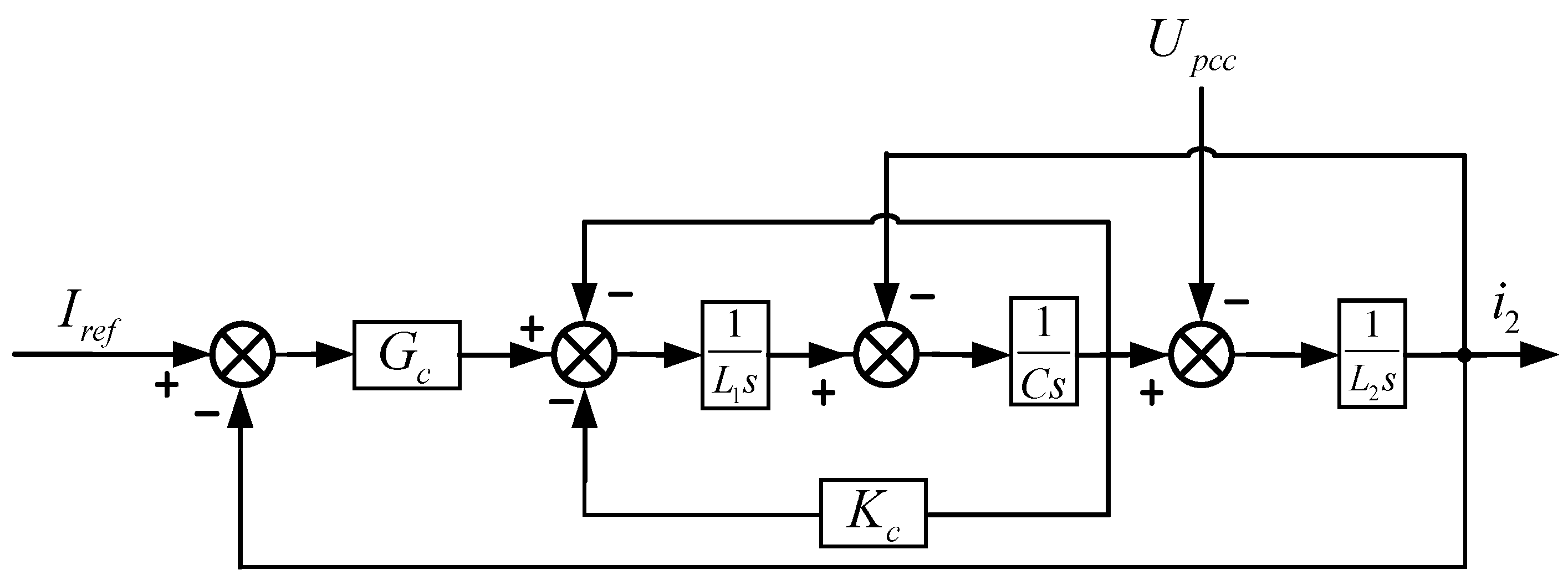
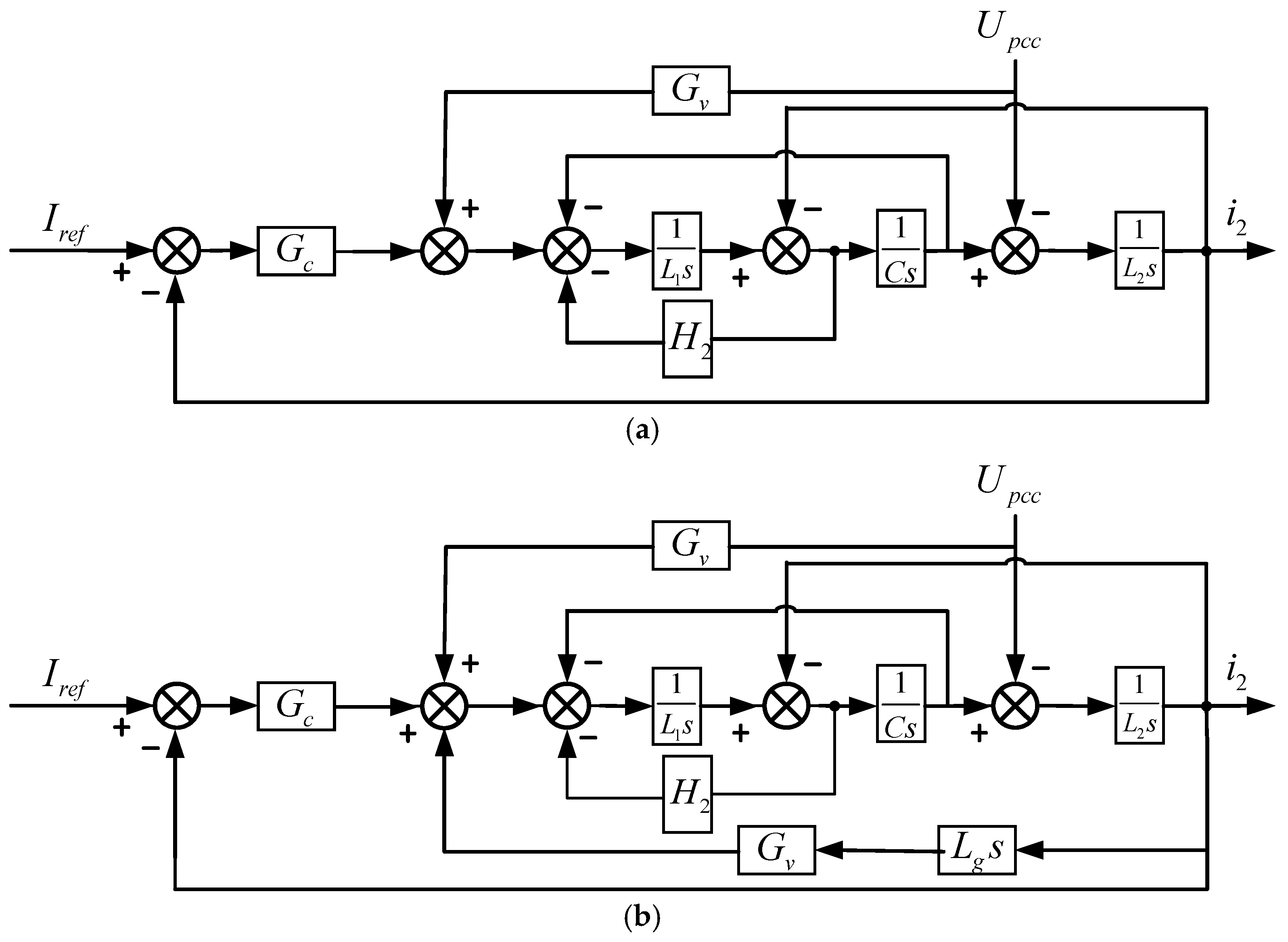
Figure 2 illustrates the basic control block diagram without considering active damping and grid impedance, which involves delay equivalence issues. Reference [
21] proposes employing a compensator based on the equal-area method to eliminate the impact caused by system delay. Once the system is fully compensated, the delay can be equivalently represented as a proportional element with a gain of 1. Since the switching frequency of this model significantly exceeds the open-loop cutoff frequency, the equivalent transfer function
from the modulation wave to the inverter side of the full-bridge inverter circuit can be approximated as:
In the formula: represents the amplitude of the DC-side voltage; denotes the amplitude of the single-pole double-frequency triangular carrier wave. In this paper, the of the inverter and the current controller have undergone normalization processing, denoted as .
From the control block diagram in
Figure 2, the transfer function
between the input current
and the current reference value
can be derived as follows:
where
is the resonant frequency of the LCL filter, which is typically set to 10 times the fundamental frequency of the power grid and less than 0.5 times the sampling frequency, and
is the corresponding resonant angular frequency satisfying
. The expression for
is:
According to
Figure 2, under grid voltage disturbance conditions, the transfer function
of the output current
with respect to the common coupling point voltage
is:
From the system equivalent control block diagram and Equations (2) and (3), the expression for the grid-connected current
is given by:
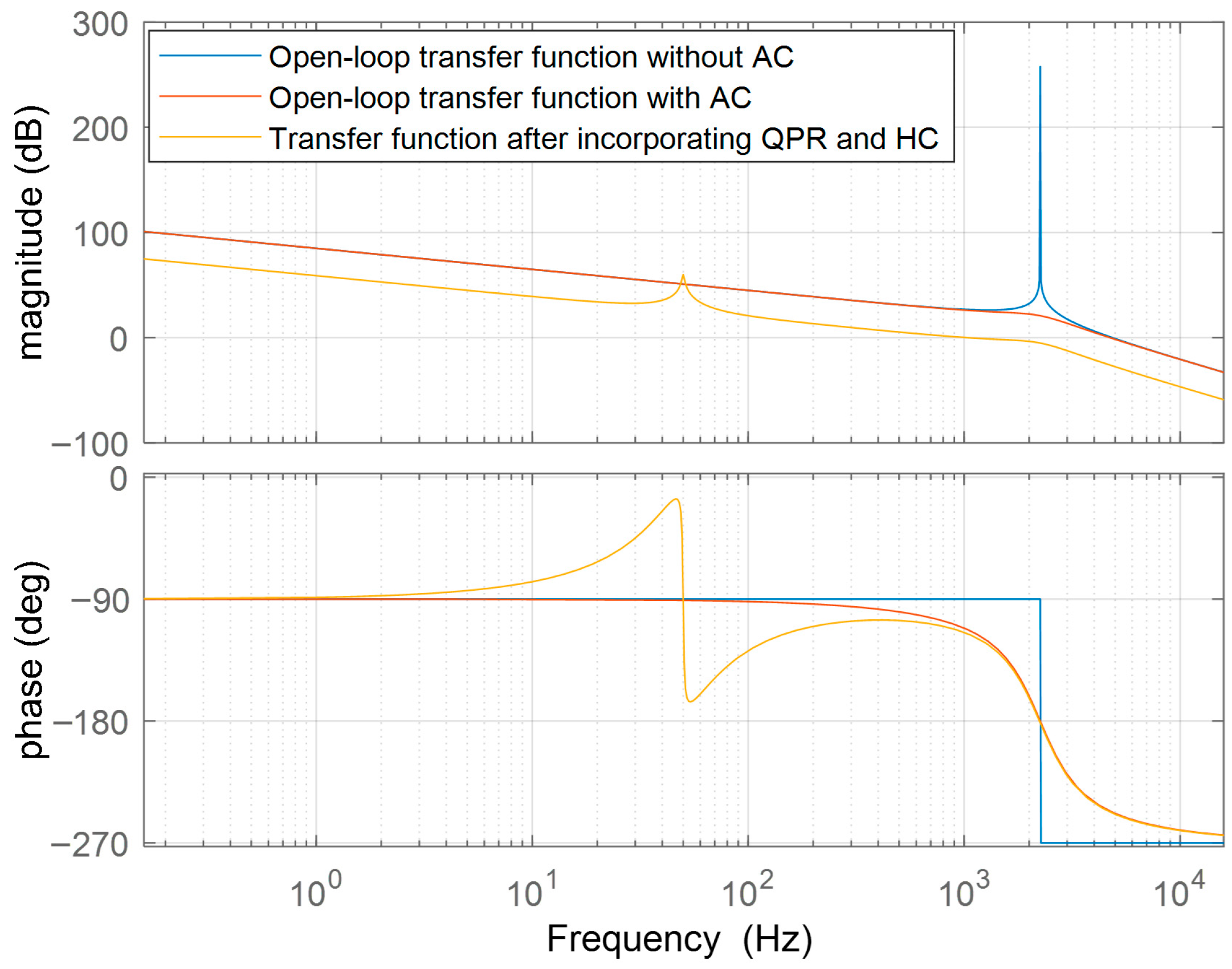
Equation (2) lacks a quadratic damping term, rendering it incapable of suppressing the resonant effects introduced by the filter. In Equation (6), the grid-connected current is influenced by the coupling point voltage, which in turn is affected by grid impedance and harmonics. Therefore, it is necessary to investigate methods for suppressing grid background harmonics.
5. Simulation and Results Analysis
To validate the improvement in grid-connected current quality achieved by the control strategy proposed in this paper, a single-phase LCL grid-connected inverter simulation model was constructed in Matlab (R2022a)/Simulink. Its model parameters are shown in
Table 1:
To simulate the higher-order harmonics present in real power grids, 3rd, 5th, and 7th harmonic components were introduced in series into the grid, with their respective amplitudes set at 10%, 6%, and 3% of the fundamental wave amplitude. Current performance under various operating conditions was verified against the background of odd-order harmonics in the grid. As shown in
Figure 10 both control strategies produce favorable current waveforms when grid impedance
.
Figure 11 compares traditional full feedforward control with improved feedforward control at
. Traditional full feedforward exhibits significant harmonics during the first two cycles, improving after 0.04 s but still showing waveform distortion and residual harmonics.
Figure 12 presents the comparative waveforms of both control strategies at
. It is evident that the traditional feedforward control exhibits severe grid-connected current distortion with significant harmonics, and substantial errors exist between the current amplitude and the reference value.
Table 2 presents the grid-connected current Total Harmonic Distortion (THD) for different control strategies under varying grid impedances. The adaptive resonant feedforward control data regarding its impact on grid-connected current harmonic content is referenced from [
23].
As shown in
Figure 10, under ideal grid impedance conditions (Lg = 0 mH), the grid-connected current waveforms of the three control strategies exhibit distinct performance gradients. While the traditional full feedforward control (a) maintains a basic sinusoidal shape, it displays noticeable high-frequency ripples and zero-crossing distortion, revealing an insufficient capability to suppress switching noise. The adaptive active damping control strategy (b) further refines dynamic response, achieving reduced overshoot and oscillations through real-time parameter adjustment. The improved composite control strategy (c) produces a nearly perfect sinusoidal waveform. Its smooth, flat curve validates the optimisation effect of the feed-forward component and highlights the precise suppression capability of the multiresonance controller for specific harmonics. This stepwise improvement in performance conclusively demonstrates that the proposed composite control strategy can achieve a leap from ‘basic stability’ to ‘high-quality output’, even under severe grid conditions, thus laying a solid foundation for outstanding subsequent performance under weak grid conditions.
As shown in
Figure 11, under the moderately weak grid condition with grid impedance Lg = 5 mH, the differences in performance between the three control strategies become much more pronounced. The waveform of the traditional full feedforward control (a) shows pronounced distortion, with oscillations at the zero-crossing point and flat-top distortion at current peaks. The adaptive active damping control strategy (b) achieves satisfactory steady-state performance under weak grid conditions; however, its limitations become apparent when compared with the improved feedforward strategy (c). The adaptive approach exhibits a relatively slower dynamic response during transient conditions, with a noticeable phase lag in current tracking observed during periods of grid disturbance. In contrast, the enhanced composite control strategy (c) maintains an almost ideal sinusoidal waveform. Its smooth curve profile and precise zero-crossing characteristics demonstrate the effective overcoming of the negative impact of grid impedance by the synergistic effect of the improved resonant feedforward and multi-resonant controllers. This approach ensures system stability while delivering superior power quality.
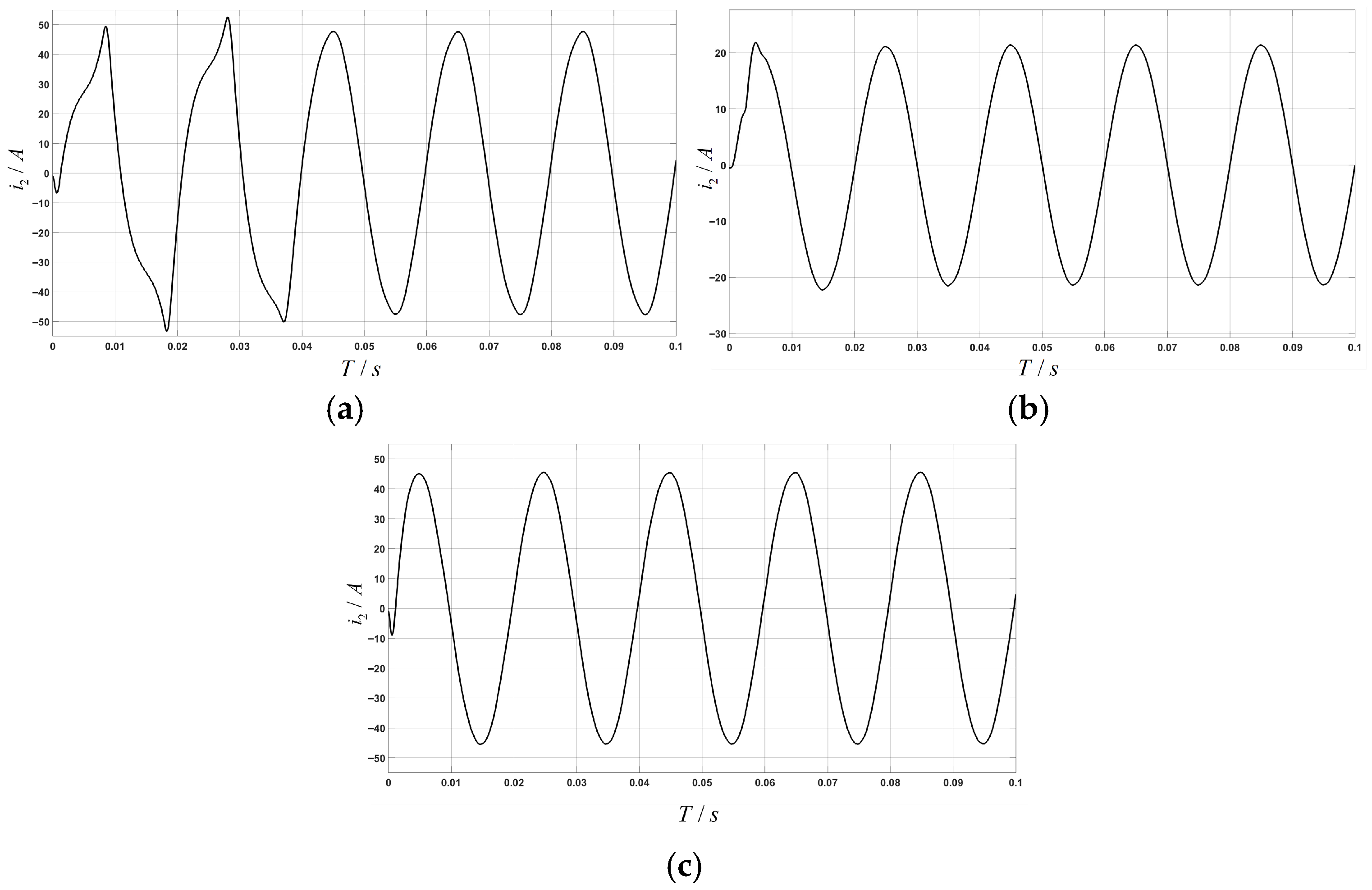
As shown in
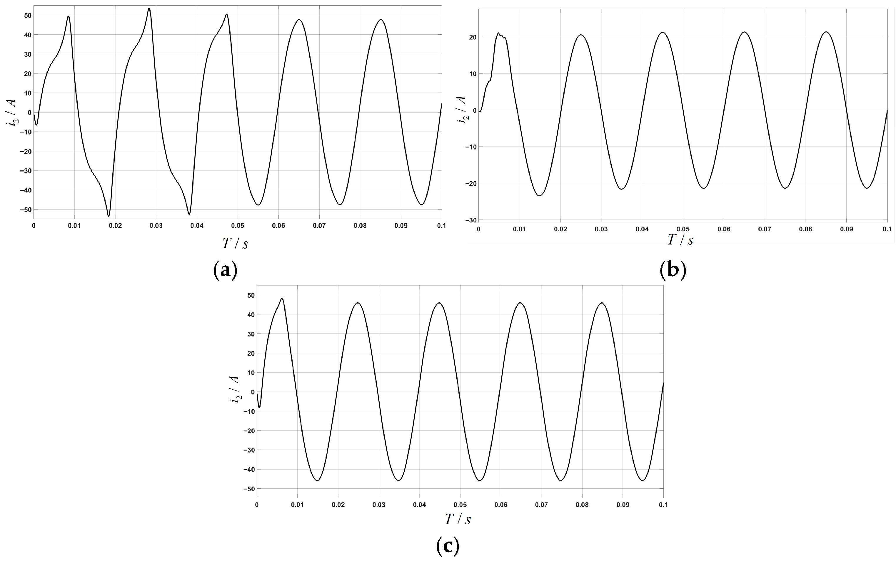
Figure 12, under the extreme weak grid condition with grid impedance Lg = 10 mH, the performance differences between the three control strategies become critical. Traditional full feedforward control (a) has become completely unstable, resulting in severe non-linear distortion of the waveform. It has lost its sinusoidal characteristics and shows significant amplitude decay and phase shift, indicating that the control system can no longer properly track the reference command. The adaptive active damping control strategy (b) produces a stable sinusoidal waveform, but noticeable current overshoot occurs during transient periods, especially when responding to sudden changes in load. This phenomenon, accompanied by low-frequency oscillations during recovery, indicates limitations in the system’s dynamic response capability. Furthermore, close inspection reveals minor harmonic distortions near the current peaks, suggesting that specific harmonic components are not being adequately suppressed. In contrast, the enhanced composite control strategy (c) maintains excellent sinusoidal waveform characteristics under such severe conditions, exhibiting only slight smoothing at the peak. This fully demonstrates the strong adaptability of the enhanced resonant feedforward mechanism to grid impedance variations, and the outstanding performance of the multi-resonant controller in maintaining system stability and current quality under extreme conditions.
As illustrated in
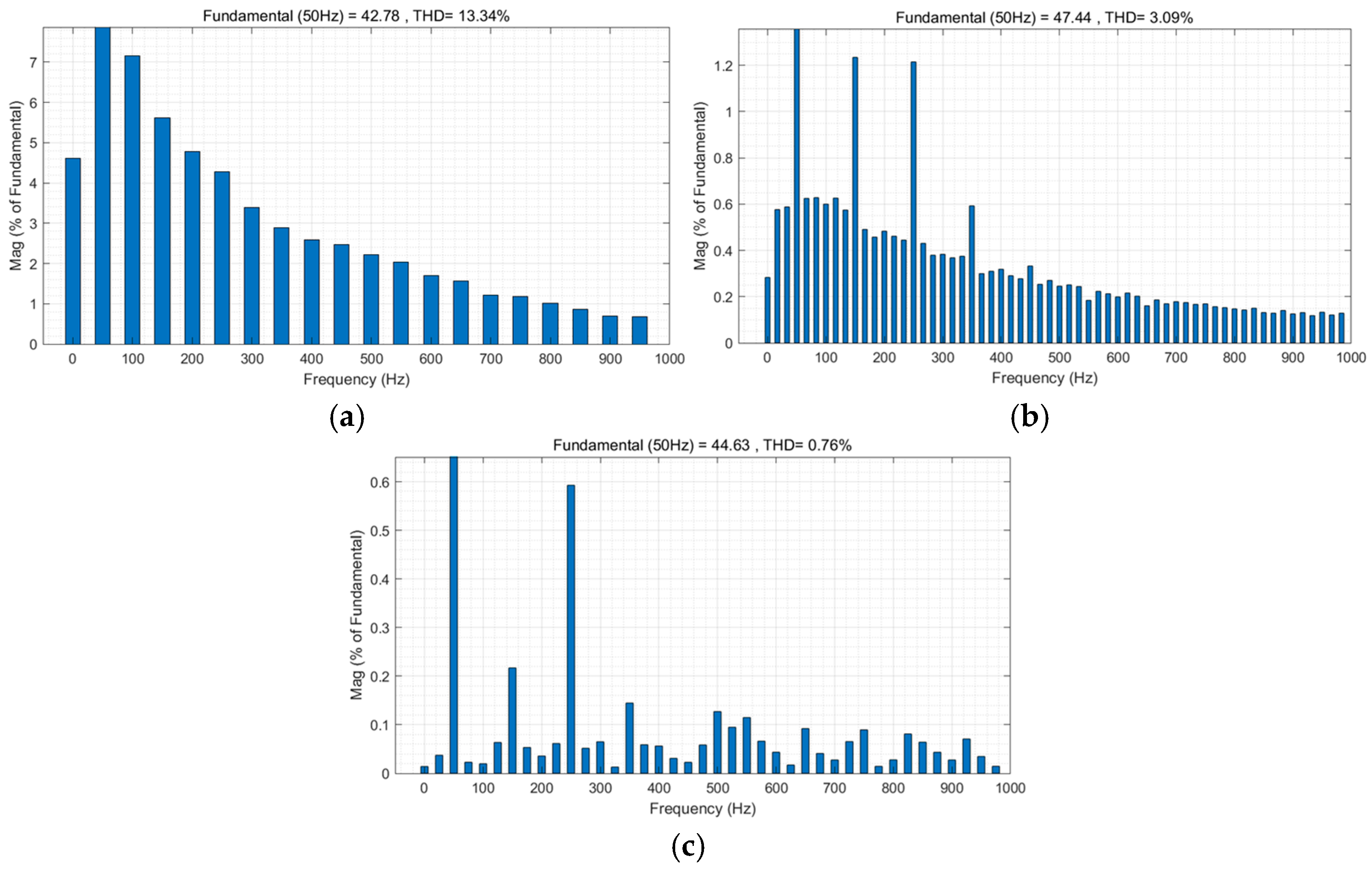
Figure 12, the enhanced control strategy incorporates a resonant component within the feedforward loop. This element reduces grid impedance at frequencies beyond the fundamental frequency, while maintaining the disturbance cancellation capability of the fundamental feedforward. Consequently, the original and improved grid-connected current waveforms both exhibit favourable characteristics. This paper performs Fourier decomposition on these waveforms and compares their harmonic content with that of traditional and adaptive feedforward control. As illustrated in
Figure 13c, the enhanced feedforward control strategy demonstrates exceptional performance, even under the stringent condition of a 10 mH grid impedance. Not only does this strategy significantly reduce the amplitude error of the grid-connected current to 0.26 A, it also achieves excellent harmonic suppression: the sixth harmonic content is suppressed to 0.1%, while all other harmonics are controlled below 0.2%. Consequently, the total harmonic distortion (THD) falls well below the 5% grid connection standard. This exceptional performance is due to the innovative integration of resonant elements into the traditional feedforward architecture. This approach effectively suppresses high-frequency harmonics induced by grid impedance and completely eliminates disturbance waves. It achieves a unified balance between precise control and robust disturbance immunity. Compared to traditional full-feedforward strategies (a) and adaptive strategies (b), this approach strikes a superior balance between control accuracy, harmonic suppression depth and engineering practicality, providing a reliable technical solution for delivering high-quality grid-connected power.
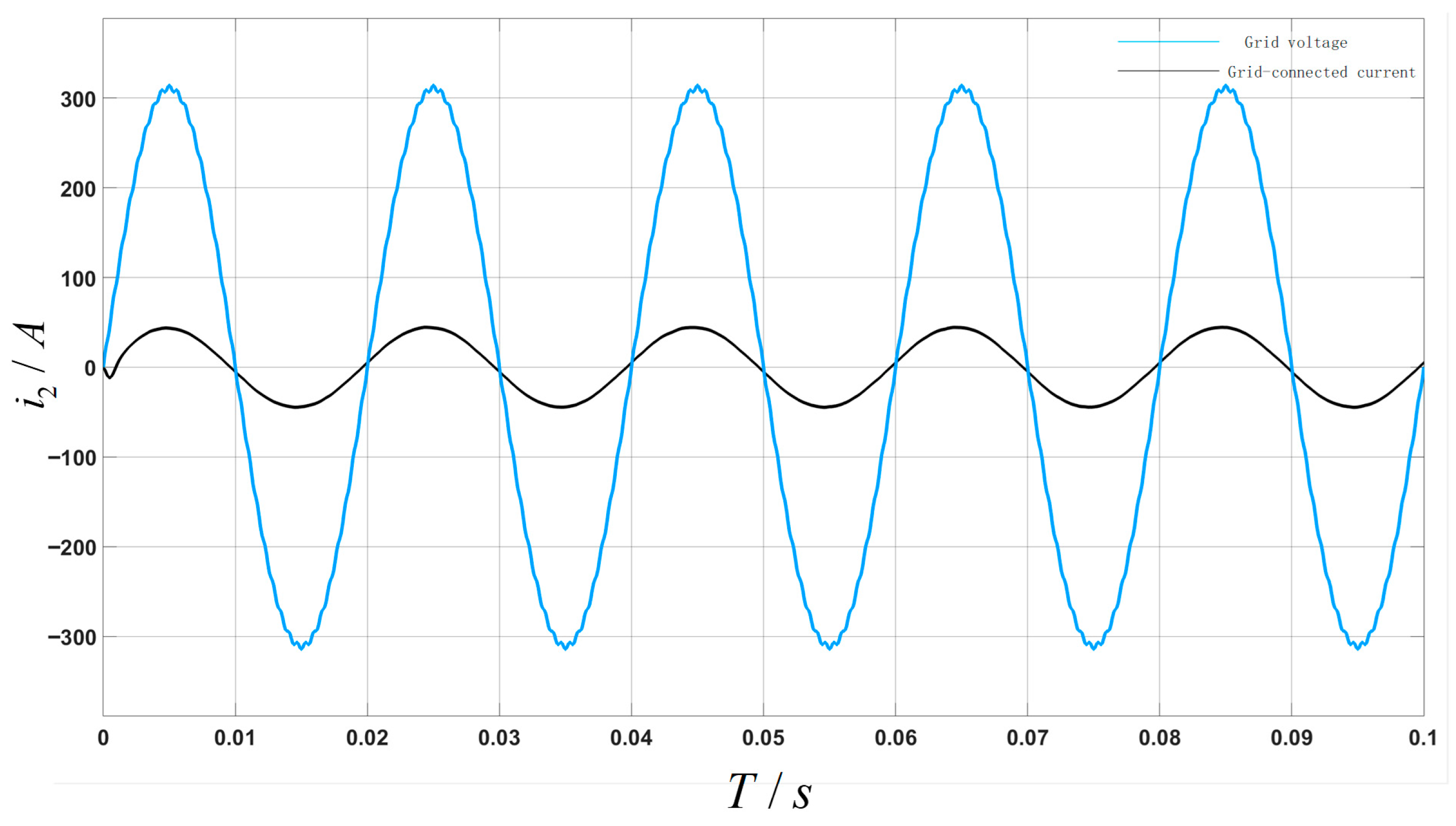
Figure 14 shows the dynamic response waveform of the system during a grid voltage sag fault, following the implementation of the improved feedforward and multi-resonance control composite strategy. The simulation results show that, when the grid voltage suddenly sags, the grid-connected current rapidly and smoothly transitions to the new reference value with no noticeable oscillations or instability occurring throughout the transient process. The current waveform maintains good sinusoidal quality during dynamic regulation, with low harmonic distortion and a rapid transition to a new stable state within milliseconds. The excellent dynamic performance of the system validates the proposed control strategy. The enhanced resonant feedforward effectively senses and compensates for grid voltage disturbances, significantly improving the speed of the system’s response and its immunity to disturbances. Meanwhile, the multi-resonance controller effectively suppresses harmonic components during transients, ensuring precise current tracking and waveform quality. These results demonstrate that the proposed strategy exhibits excellent dynamic performance and robustness when confronted with severe disturbances, such as grid faults.
Figure 15 shows the dynamic response waveform of the grid-connected current when 33rd-harmonic disturbances are injected into the power grid following the implementation of an improved control strategy. Unlike in the voltage dip scenario, this waveform primarily demonstrates the suppression capability of the control strategy for specific high-frequency harmonics: after 33rd harmonic injection, the grid-connected current maintains a well-defined sinusoidal waveform without any noticeable high-frequency oscillations or waveform distortion. This suggests that the multiresonance controller in the proposed strategy has significant filtering effects on higher-order harmonics. The enhanced feedforward channel works with the resonant controller to eliminate the impact of background grid harmonics on current tracking accuracy. This ensures steady-state performance and power quality for the system under high-frequency disturbances, demonstrating the strategy’s ability to suppress harmonics across multiple frequency bands.
6. Hardware-in-the-Loop Experimental Results
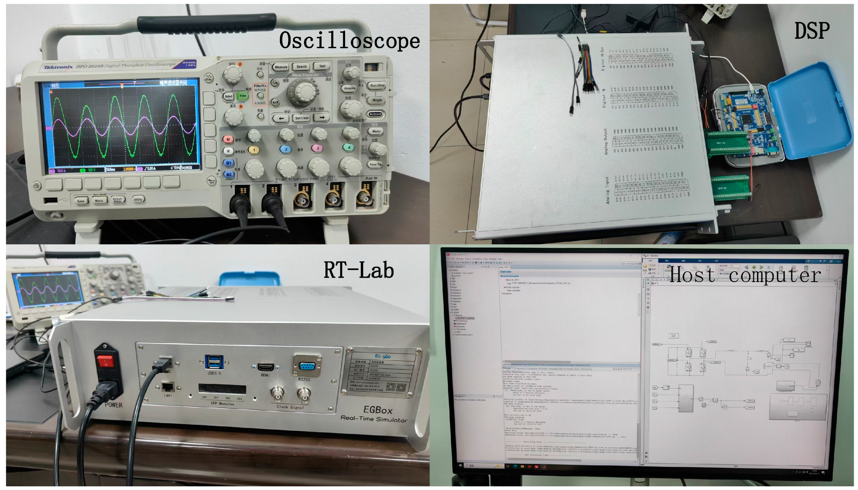
To further validate the correctness and effectiveness of the voltage control method for single-phase grid-connected inverters proposed in this paper, a hardware-in-the-loop semi-physical simulation experiment was conducted using the RT-LAB simulation platform. The voltage fault conditions during the experiment matched the simulation settings. The RT-LAB semi-physical simulation platform is shown in
Figure 16.
Figure 17b shows the improved feedforward control strategy, which demonstrates outstanding dynamic performance with a rapid current response and precise tracking. Its proactive compensation mechanism enables it to rapidly suppress disturbances. While it exhibits slight waveform adjustments, it responds highly efficiently to system variations, making it particularly suitable for grid-connected applications that demand high dynamic performance.
Figure 18b shows the test waveform of the improved feedforward control strategy, which demonstrates its core advantages even when confronted with the greater challenges posed by l = 5. Compared to adaptive active damping (a), which is robust but may exhibit conservative responses, the improved feedforward control achieves a faster dynamic response, enabling swift tracking of command changes. Its key value lies in proactively compensating for system disturbances through a forward-looking mechanism, thereby demonstrating greater adaptability and disturbance rejection potential under complex operating conditions. Although the steady-state waveform exhibits slight ripples, these precisely reflect the controller’s active and rapid processing of system dynamics.
Even under the stringent condition of increased inductance to L = 10, the improved feed-forward control strategy shown in
Figure 19b demonstrates superior adaptability to changes in performance compared to the adaptive active damping strategy shown in
Figure 19a. Its waveform response is fast and precise, demonstrating the unique ability of the feedforward mechanism to overcome system inertia caused by high inductance. Despite the more complex operating conditions, this strategy effectively suppresses disturbances through proactive compensation, ensuring rapid system stabilisation.
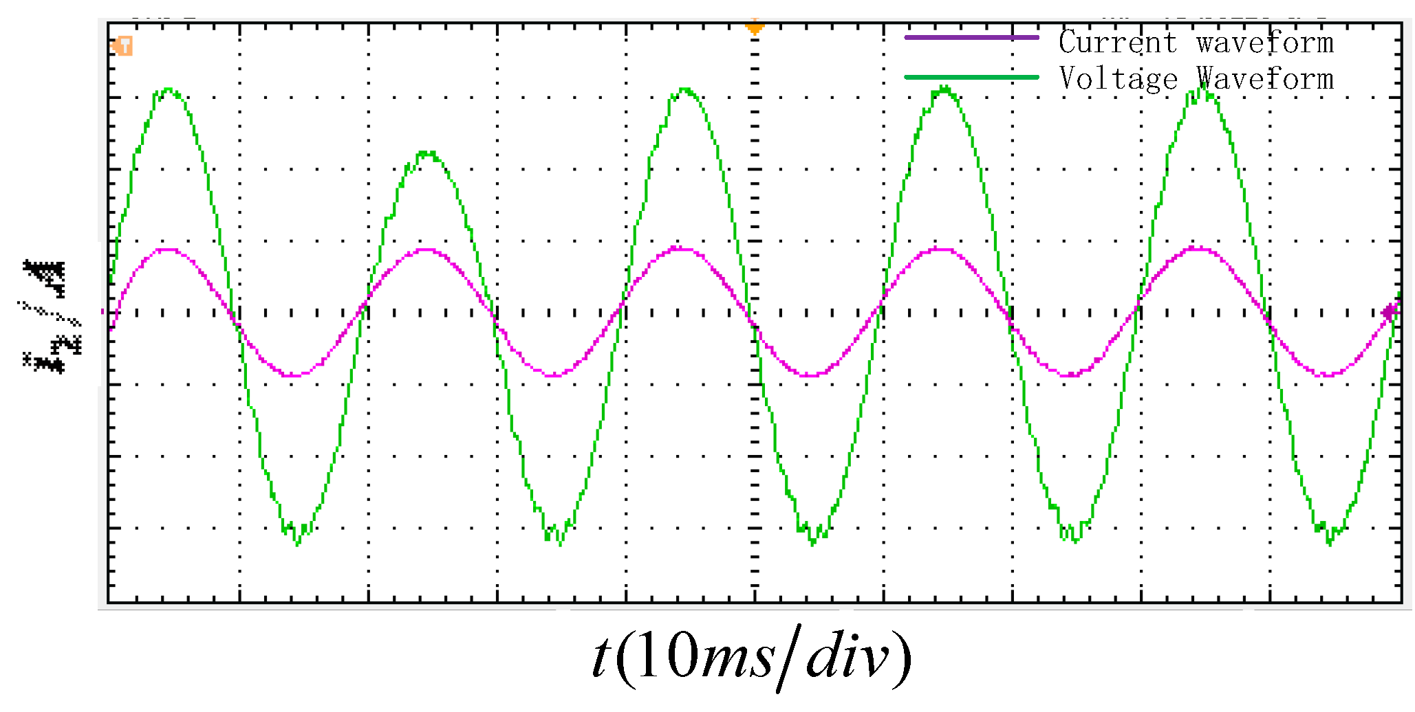
Figure 20 illustrates the dynamic response of the grid-connected current during a sudden voltage dip. As can be seen, at the instant of the voltage drop and recovery, the current fluctuates briefly before stabilising rapidly, which demonstrates the exceptional dynamic response and disturbance rejection capability of the control strategy. Throughout the sustained voltage dip, the current maintains an excellent sinusoidal waveform, which validates the method’s robustness and stable operation under severe conditions.
The improved feedforward control strategy proposed in this paper, based on the aforementioned hardware-in-the-loop experiments, demonstrates superior dynamic response performance, enhanced disturbance rejection capability and excellent operational stability under various inductance conditions and voltage sag scenarios.
7. Conclusions and Outlook
This paper proposes a hybrid control strategy combining an improved resonant feedforward controller with a proportional multiresonant controller. It aims to address multiple challenges faced by LCL grid-connected inverters in weak grid environments, including inherent resonance, grid impedance, and background harmonics. Simulation results validate the effectiveness of this strategy. This section will delve into these results and analyze the advantages, underlying mechanisms, and applicability of the proposed method.
7.1. Synergistic Effects of Composite Control Strategies
This study focuses on recognising the limitations of single-control approaches and seeking a synergistic solution. The simulation results show that the proposed composite strategy outperforms traditional full-feedforward and single-improvement methods when it comes to addressing grid impedance variations and background harmonic interference. This advantage stems from the effective complementarity of the two control methods.
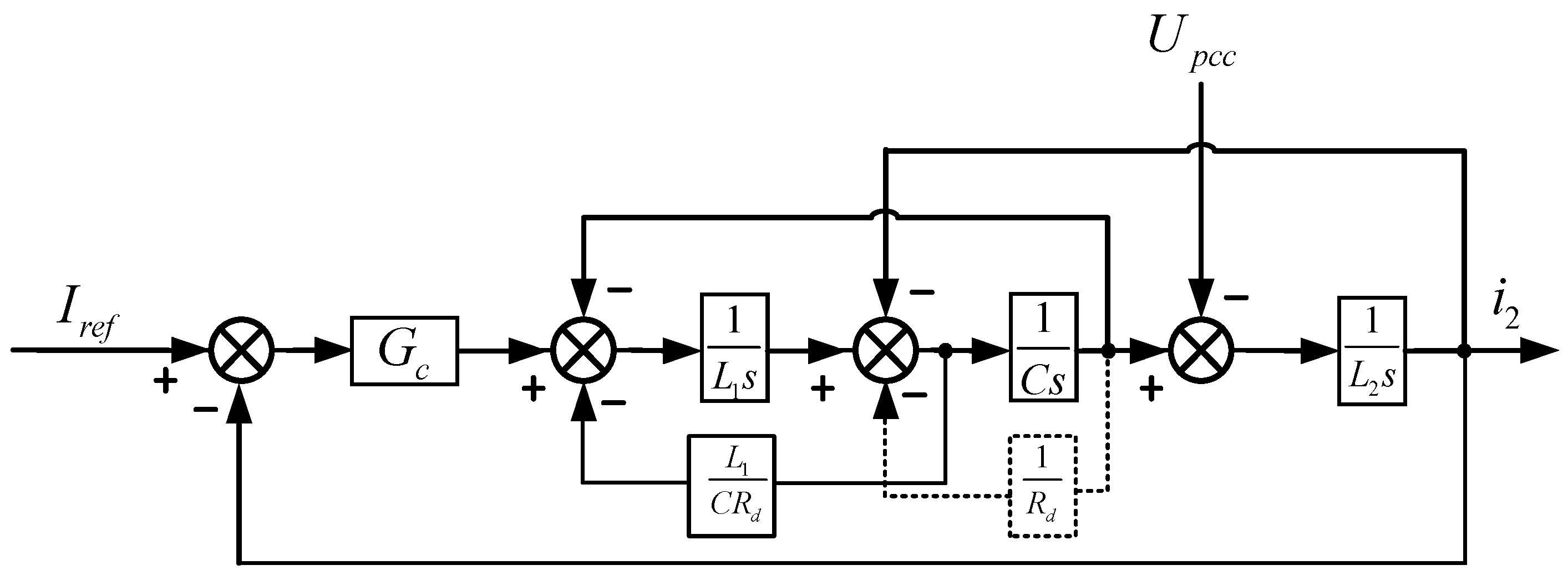
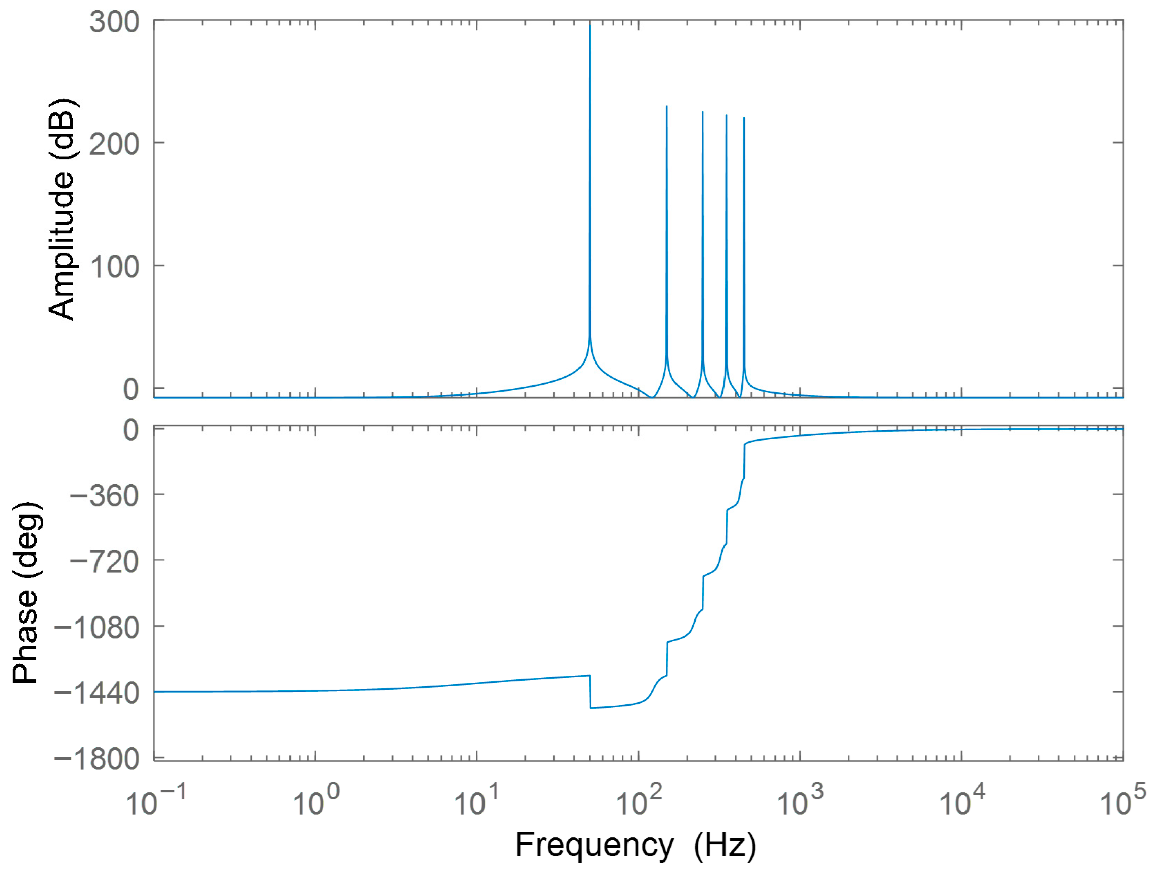
The role of improved resonant feedforward: As illustrated in
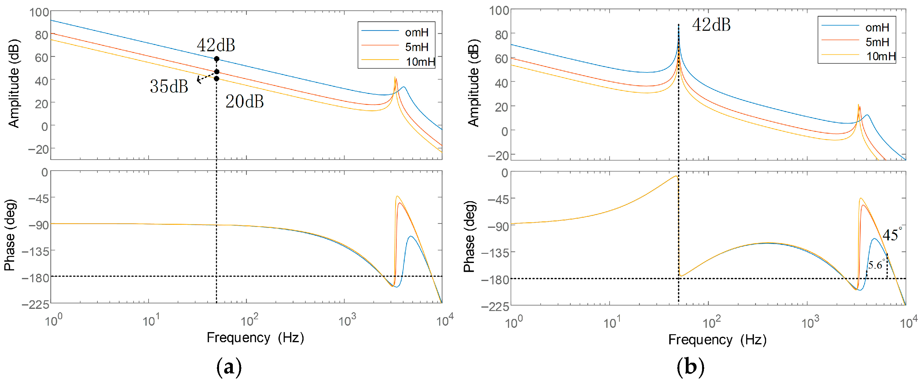
Figure 9 and
Table 2, improved resonant feedforward effectively addresses the issue of significant system stability deterioration caused by increased grid impedance in traditional full feedforward control (as depicted in
Figure 7). The key lies in its precise compensation of feedforward at specific frequencies (primarily fundamental frequencies). This offsets voltage drops caused by grid impedance at these frequencies, maintaining the system’s reference tracking accuracy (i.e., the fundamental gain remains constant regardless of impedance changes). It also avoids introducing additional phase lag across the entire frequency band, thereby ensuring the system’s stability margin under weak grid conditions.
Figure 9 confirms this, showing the system maintaining sufficient phase margin under varying grid impedances.
The role of the proportional multiharmonic controller: As shown in
Table 2 and
Figure 14, the total harmonic distortion (THD) of the grid-connected current is significantly lower under the composite control strategy than under traditional methods. There is particularly effective suppression of higher-order harmonics, such as the sixth harmonic. This is primarily due to the high gain provided by the proportional multiresonance controller at characteristic harmonic frequencies, such as the fundamental frequency and the 3rd, 5th and 7th harmonics. This enables zero-steer tracking of the command current and effective suppression of harmonic disturbances of the same order in the grid voltage. Consequently, it compensates for the limitations of using improved feedforward alone to suppress low-order harmonics present in the grid background.
7.2. Performance Comparison with Traditional and Advanced Control Strategies
The THD data in
Table 2 provides an intuitive performance comparison. Compared to the traditional full feedforward control method, the proposed method optimises THD from 2.45% to 1.80% under weak grid conditions (Lg = 0 mH), demonstrating superior steady-state performance even in the absence of grid impedance influence. However, as grid impedance increases to Lg = 10 mH, the traditional method becomes unstable, causing THD to surge to 13.34%. In contrast, the proposed method optimises THD further to 0.76%, fully demonstrating its effectiveness and robustness under severe weak grid conditions.
The proposed approach demonstrates comparable competitiveness to the advanced active control method. At 10 mH, the THD of the proposed method is 0.76%, which is lower than that of the active control strategy (3.64%). This shows that, despite not using complex online parameter identification and adaptive adjustment mechanisms, combining a carefully designed fixed-parameter resonant feedforward with a multi-resonant controller efficiently and robustly suppresses specific disturbances (impedance and characteristic subharmonics) while keeping the control system simple. This provides a valuable solution for balancing control performance and system complexity in engineering practice.
7.3. Compared with Adaptive Control
To further validate the superiority of the proposed strategy, it was compared with an adaptive feedforward control strategy. When the grid impedance increased to 10 mH under severe conditions, the total harmonic distortion (THD) of the grid-connected current under adaptive control reached 3.09%. While adaptive control can theoretically adapt to changes in the system through online parameter adjustment, this result suggests that its performance in practical applications may be limited by the accuracy of parameter identification, the speed of convergence and the complexity of the algorithm. Performance may degrade or become unstable under strong disturbances. In contrast, the improved fixed-parameter resonant feedforward and quasi-proportional multi-resonance composite control strategy achieves a significantly lower THD of 0.76%, eliminating the need for complex online identification or adaptive adjustment mechanisms. This demonstrates that the strategy effectively locks onto and suppresses critical disturbances caused by grid impedance and background harmonics of a specific order through its carefully designed fixed control structure. Consequently, it provides a more reliable and robust solution in extremely weak grid conditions. Therefore, this strategy strikes a better balance between control performance, system complexity, and engineering feasibility, offering a highly practical alternative for addressing weak grid challenges.
7.4. Dynamic Performance and Robustness Analysis
Figure 14 and
Figure 15 demonstrate the superiority of the proposed strategy by showing how it responds dynamically to changes. During both the reference current jump and the grid impedance step changes, the system recovers stability rapidly within one cycle, with minimal overshoot and oscillation. This performance stems from two key factors. Firstly, enhanced resonant feedforward maintains the system’s stability margin, providing a foundation for a fast dynamic response. Secondly, the proportional gain in the proportional-resonant controller ensures sufficient bandwidth, enabling a quick response to changes in commands and effective suppression of disturbances.
7.5. Limitations and Future Prospects
This study validated through simulation the significant advantages of the proposed improved composite control strategy in enhancing grid-connected current quality, suppressing resonance, and strengthening system stability. It provides valuable theoretical references and solutions for high-performance control of LCL grid-connected inverters.
Looking ahead, this research can be deepened in the following directions: Exploring the integration of advanced algorithms such as adaptive control and artificial intelligence with feedforward multiresonance control can enhance the robustness and adaptability of this strategy in complex dynamic power grid environments. Finally, promoting the application of this strategy in multi-machine parallel systems of large-scale renewable energy power plants will provide key technical support for achieving the safe and stable grid integration of high-penetration renewable energy.
