Abstract
Magnesium metal boasts a high theoretical volumetric specific capacity and abundant reserves. Magnesium batteries offer high safety and environmental friendliness. In recent years, magnesium-ion batteries (MIBs) with Mg or Mg alloys as anodes have garnered extensive interest and emerged as promising candidates for next-generation competitive energy storage technologies. However, MIBs are plagued by issues such as sluggish desolvation kinetics and slow migration kinetics, which lead to limitations including a limited electrochemical window and poor magnesium storage reversibility. Herein, the sodium vanadium phosphate @ carbon (Na3V2(PO4)3@C, hereafter abbreviated as NVP@C) cathode material was synthesized via a sol–gel method. The electrochemical performance and magnesium storage mechanism of NVP@C in a 0.5 M magnesium bis(trifluoromethanesulfonyl)imide/ethylene glycol dimethyl ether (Mg(TFSI)2/DME) electrolyte were investigated. The as-prepared NVP@C features a pure-phase orthorhombic structure with a porous microspherical morphology. The discharge voltage of NVP@C is 0.75 V vs. activated carbon (AC), corresponding to 3.5 V vs. Mg/Mg2+. The magnesium storage process of NVP@C is tentatively proposed to follow a ‘sodium extraction → magnesium intercalation → magnesium deintercalation’ three-step intercalation–deintercalation mechanism, based on the characterization results of ICP-OES, ex situ XRD, and FTIR. No abnormal phases are generated throughout the process, and the lattice parameter variation is below 0.5%. Additionally, the vibration peaks of PO4 tetrahedrons and VO6 octahedrons shift reversibly, and the valence state transitions between V3+ and V4+/V5+ are reversible. These results confirm the excellent reversibility of the material’s structure and chemical environment. At a current density of 50 mA/g, NVP@C delivers a maximum discharge specific capacity of 62 mAh/g, with a capacity retention rate of 66% after 200 cycles. The observed performance degradation is attributed to the gradual densification of the CEI film during cycling, leading to increased Mg2+ diffusion resistance. This work offers valuable insights for the development of high-voltage MIB systems.
1. Introduction
The crustal abundance of magnesium is 2%. The reserves of magnesium in seawater exceed 1015 tons. These two characteristics together provide significant advantages in resource security and cost-effectiveness [,,,,]. As an anode material, metallic magnesium anodes have a high theoretical specific volumetric capacity (up to 3833 mAh/cm3) and exhibit no dendrite growth during deposition/dissolution. This absence of dendrite growth ensures excellent safety []. Benefiting from these unique advantages, magnesium-ion batteries have become potential candidates for next-generation large-scale energy storage technologies.
The performance of cathode materials is the bottleneck that restricts the energy density and cycle stability of magnesium-ion batteries. Currently, the commonly used cathodes for magnesium-ion batteries mainly include transition metal oxides [,,], transition metal sulfides [,,,], olivines [,,], spinels [,,], and so on. Traditional cathode materials such as Chevrel-phase Mo6S8 (operating potential ~0.75 V vs. Mg2+/Mg) [] and layered TiS2 (~0.6 vs. Mg2+/Mg) [] generally suffer from low operating potential and poor magnesium storage reversibility. These limitations mean that they cannot meet the application requirements of energy storage. As a typical NASICON (Sodium Super Ionic Conductor) structured material, sodium vanadium phosphate (Na3V2(PO4)3, abbreviated as NVP) has a key advantage of high operating potential [,,,,]. In sodium-ion battery systems, NVP@C has achieved a high operating potential (3.4 V vs. Na+/Na) and an energy density of 400 Wh/kg [,], which makes NVP adapt the need of high operating potential and high energy density during charge–discharge. NVP has a 3D open framework composed of VO6 octahedra and PO4 tetrahedra that share vertices. This framework exhibits small volume variation during charge–discharge and excellent stability, which in turn alleviates lattice stress caused by ion intercalation/deintercalation []. Forming an amorphous carbon layer on the NVP surface can significantly improve electronic conductivity, which can address the low conductivity defect []. After 300 cycles at 10 C, the NVP@C composite retains 85% of its capacity, which verifies the material’s structural stability and cycle durability []. Moreover, the mesoporous structure of NVP@C (surface area 195 m2/g) shortens diffusion paths, which enhances ion diffusivity [].
Electrolyte performance directly determines three battery properties: ion migration efficiency, interface stability, and operating voltage window. TFSI-based electrolytes are ideal for matching high-potential NVP@C cathodes because they have weak coordination properties that optimize ion–solvent interactions. Furthermore, the strong charge delocalization and large size of TFSI-ions endow these electrolytes with lower viscosity and higher ionic conductivity [,]. For example, the NaTFSI/TMP (trimethyl phosphate) electrolyte used in sodium-based dual-carbon batteries have a high cut-off voltage (4.0 V vs. Na/Na+) and excellent electronic conductivity []. The polyethylene oxide-based electrolyte (PEO20:NaTFSI + 5% wt SiO2) prepared via solvent-free hot-pressing exhibits excellent conductivity, good mechanical properties, and a wide electrochemical window [].
The synergy between NVP@C cathodes and TFSI-based electrolytes has yielded results in sodium-ion batteries. When 3 wt% sacrificial LiTFSI is added to the 0.75 mol/L NaClO4-FEC/PC electrolyte (denoted as F/P), the “reductive competition effect” between LiTFSI and FEC constructs a unique solid electrolyte interphase (SEI) with uniformly dispersed inorganic components and high conductivity. The full-cell system composed of this modified electrolyte and Na||NVP@C maintains a high discharge voltage (3 V vs. Na+/Na) at −35 °C, while also exhibiting low polarization voltage and stable cycle performance []. The sodium-ion battery composed of a mixed electrolyte 1 M NaFSI and ionic liquid C3mpyrTFSI in a 50:50 volume ratio and an NVP@C cathode forms an SEI film on the electrode surface; this film has low resistance and high Na+ permeability, which significantly improves the battery’s cycle stability []. The battery system, constructed from three components: sodium bis(trifluoromethanesulfonyl)imide (NaTFSI)-succinonitrile (SN)-fluoroethylene carbonate (FEC)” ternary electrolyte, metallic sodium anode, and NVP@C cathode, has a voltage range of 2.8–3.8 V vs. Na/Na+, and achieves a reversible specific capacity of 106.9 mAh/g at 0.1 C with good rate performance. During battery cycling, the TFSI-anion of NaTFSI undergoes reductive decomposition; its products (e.g., Na3N) serve as important inorganic components of the SEI layer. The inorganic phase, dominated by Na3N (from TFSI− decomposition) and NaF (from FEC decomposition), significantly improves the SEI’s ionic conductivity and compactness, inhibits Na dendrite growth, and reduces side reactions between the electrolyte and Na metal anode. These improvements together ensure the full cell’s long-term cycle stability [], which in turn guarantees the entire system’s charge–discharge reactions within a high-voltage range.
The synergy between NVP@C cathodes and TFSI-based electrolytes is expected to improve the operating voltage of magnesium-ion batteries, and this synergy may further form the core system of high-voltage magnesium-ion batteries. On the one hand, the three-dimensional open framework of NVP@C provides sufficient diffusion channels for intercalated Mg2+ ions [], which alleviates the diffusion resistance caused by Mg2+’s high charge density (ionic radius 0.072 nm). On the other hand, Mg(TFSI)2 itself has high ionic conductivity, a wide electrochemical stability window, and excellent chemical stability. These are core electrolyte properties that make Mg(TFSI)2 a potential candidate for Mg battery electrolytes []. This property set also provides a good foundation for subsequent performance optimization, which allows full leverage of NVP@C’s high-potential advantage.
In this work, in order to clarify the three-stage “sodium extraction—magnesium intercalation—magnesium extraction” reaction mechanism of NVP@C in TFSI-based electrolytes, NVP@C is used as the cathode material and Mg(TFSI)2/DME as the electrolyte. The structure of NVP@C is characterized using such characterization methods such as X-ray diffraction (XRD), transmission electron microscopy (TEM), X-ray photoelectron spectroscopy (XPS), and Fourier transform infrared spectroscopy (FTIR). Combined with electrochemical tests including cyclic voltammetry (CV), galvanostatic charge–discharge, and electrochemical impedance spectroscopy (EIS), the mechanism of synergistic magnesium storage between NVP@C and TFSI-based electrolytes is analyzed.
2. Materials and Methods
2.1. Materials Preparation
NVP@C was prepared using the sol–gel method. Firstly, NaOH (sodium source, Chengdu Kelong Chemical Products Co., Ltd., Chengdu, China, 99.9%), NH4VO3 (vanadium source, Chengdu Kelong Chemical Products Co., Ltd., 99.9%), and NH4H2PO4 (phosphorus source, Chengdu Kelong Chemical Products Co., Ltd., 99.9%) were accurately weighed in a molar ratio of 3:2:3. Subsequently, an aqueous solution of citric acid (serving as both carbon source and chelating agent, Chongqing Chuandong Chemical Industry Co., Ltd., Chongqing, China, AR) at a mass ratio of 3% was added. The mixture was stirred and reacted at 70 °C for 8 h using a constant-temperature magnetic stirrer to form a dark blue gel. The gel was placed in a vacuum drying oven at 60 °C for 12 h to dry. After drying, the dried gel was ground into powder and transferred to a crucible. The crucible was placed in a tube furnace under an argon atmosphere. First, the crucible was pre-calcined at 350 °C for 3 h to remove organic impurities. Then, the temperature was raised to 600–800 °C for calcination for 8–16 h, finally obtaining the NVP@C material coated with in situ pyrolytic carbon derived from citric acid. The core reaction equation is as follows []:
2NH4VO3 + 2C6H8O7 + 3NaOH + 3NH4H2PO4 → Na3V2(PO4)3 + 15H2O + 4CO + 2CO2 + 5NH3 + 6C
2.2. Assembly of Coin Cells
0.5 M Mg(TFSI)2/DME electrolyte (Suzhou Duoduo Chemicals, Suzhou, China, battery grade) was used. To prepare cathode sheets, NVP@C was used as the cathode active material, mixed at a mass ratio of active material/conductive carbon black/PVDF = 7:2:1. N-methylpyrrolidone (NMP) solvent was added dropwise, and the mixture was stirred for 12 h to form a homogeneous slurry. The slurry was coated onto the surface of aluminum foil current collectors. The slurry was vacuum-dried at 80 °C for 8 h. The current collector coated with the active material was cut into cathode sheets with a diameter of 12 mm. The electrode loading of the cathode was 1.5 ± 0.1 mg/cm2. The porosity measured by mercury intrusion porosimetry was 42.3% ± 1.5%. The total electrode thickness (including aluminum foil) measured by a spiral micrometer (accuracy: 0.001 mm) was 25 ± 1 μm, with the active layer thickness being 8 ± 0.5 μm. Copper foil coated with activated carbon was used as the anode, and GF/A glass fiber as the separator. CR2032 coin cells were assembled in an argon-filled glove box (H2O/O2 < 0.1 ppm). After assembly, they were left to stand for 10 h before electrochemical tests were performed.
2.3. Characterization and Testing
2.3.1. Structural and Morphological Characterization
An X-ray diffractometer (XRD, PANalytical X’pert Powder, Panalytical B.V., Almelo, The Netherlands, Cu Kα radiation, λ = 1.5418 Å) was used to analyze the phase structure. A transmission electron microscope (TEM, Talos-F200S, Thermo Fisher Scientific, Brno, Czech) was used to observe the material microstructures. An X-ray photoelectron spectrometer (XPS, ESCALAB250Xi, Thermo Fisher Scientific, Madison, WI, USA) was used to analyze element valences and interface components. An inductively coupled plasma optical emission spectrometer (ICP-OES, ICAP 6300 Duo, ThermoFisher Scientific, Bannockburn, IL, USA) was used for the quantitative analysis of metallic elements (e.g., Na, V) in the material under different charge–discharge states. A Fourier transform infrared spectrometer (FTIR, Nicolet iS50, ThermoFisher Scientific, Bannockburn, IL, USA) was used to analyze changes in functional group vibrations.
2.3.2. Electrochemical Performance Testing
Cyclic voltammetry (CV) tests were conducted using an electrochemical workstation (CHI660E), with a voltage range of 0.01–2.0 V and a scan rate of 0.3 mV/s. Galvanostatic charge–discharge tests were performed using a NEWARE battery testing system (NEWARE CT-4000), at a current density of 50–500 mA/g and a voltage range of 0.01–2.0 V. Electrochemical impedance spectroscopy (EIS) tests were carried out to analyze reaction kinetics, with a frequency range of 0.01 Hz–10 kHz and an amplitude of 10 mV.
3. Results and Discussions
3.1. Structural and Morphological Characteristics of NVP@C
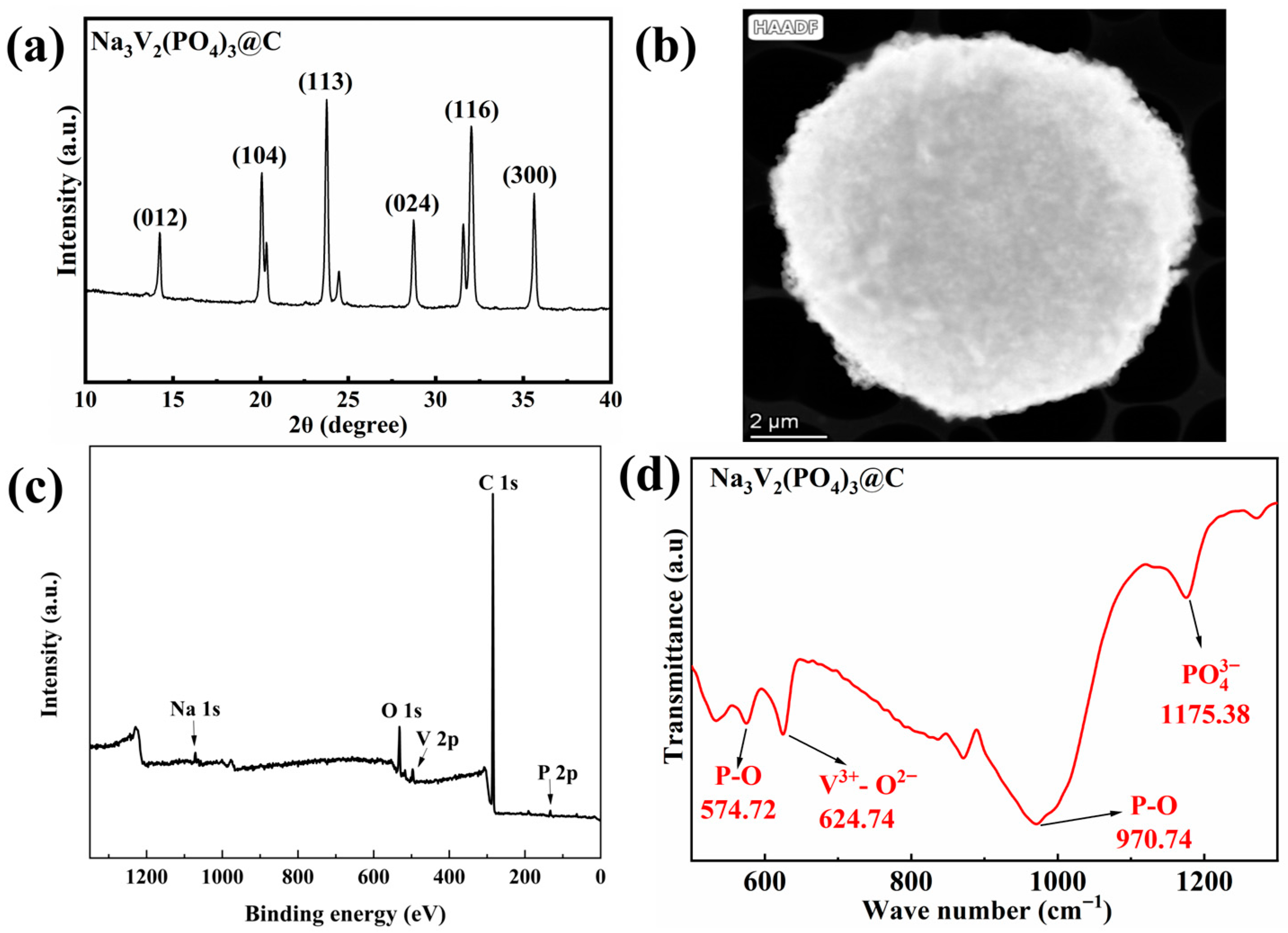
To investigate the structural and morphological characteristics of NVP@C, characterization tests were conducted. Results are shown in Figure 1. The XRD pattern of NVP@C (Figure 1a) shows that all diffraction peaks match the standard card of orthorhombic Na3V2(PO4)3 (JCPDS No.53-0018, space group R-3c). No impurity peaks appear, showing that the prepared material has a pure phase and excellent crystallinity. Among these peaks, the strongest (113) and second strongest (116) correspond to the characteristic crystal planes of the NASICON structure. No diffraction peaks of graphitic carbon appear, showing that the carbon layer is amorphous. TEM results (Figure 1b) show that NVP@C has a porous microsphere structure with sizes 5–10 μm. Small fragments (<1 μm) distribute on the surface, resulting from the partial breakage of microspheres during grinding. The XPS survey spectrum in Figure 2 confirms that five elements (Na, V, P, O, and C) exist in the material. EDS Mapping results in Figure 2 show that Na, V and C distribute uniformly in the microspheres. EDS elemental analysis shows that NVP@C has an atomic percentage of Na: 14.2%, V: 9.4%, P: 14.2%, O: 56.7%, C: U% and a corresponding mass percentage of Na: 14.7%, V: 21.7%, P: 19.8%, O: 40.9%, C: 2.9%, confirming the uniform distribution of main elements and incomplete carbon coating. Carbon distributes relatively sparsely, confirming the carbon layer’s incomplete coating.
Figure 1.
XRD pattern (a), TEM-HAADF image (b), XPS spectrum (c), FTIR spectrum (d), and EDS Mapping images.
Figure 2.
EDS Mapping images of NVP@C.
3.2. Electrochemical Performance of NVP@C
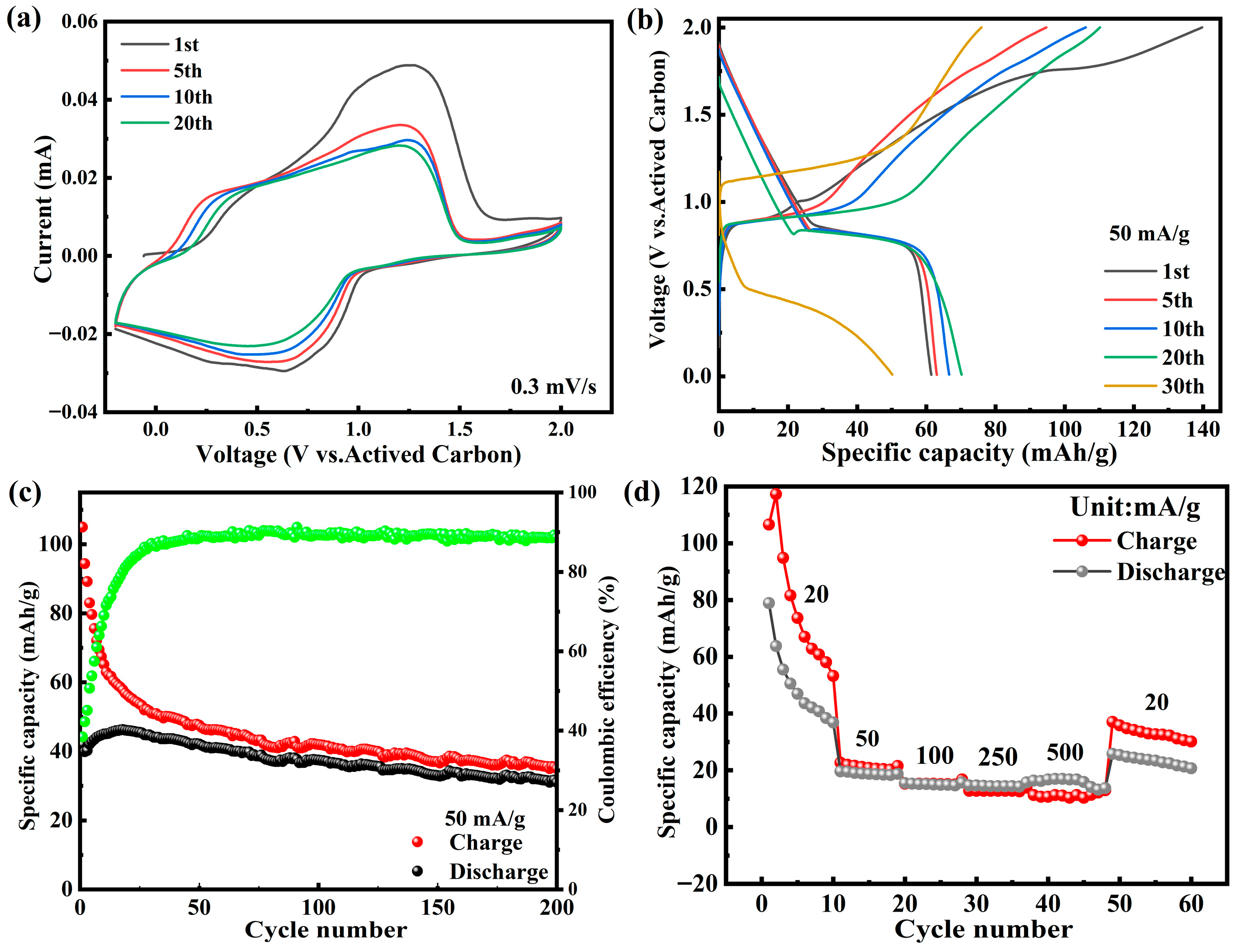
To investigate the electrochemical performance of NVP@C in Mg(TFSI)2/DME electrolyte, CV tests and charge–discharge tests were conducted on NVP in Mg(TFSI)2/DME electrolyte, with results shown in Figure 3. The CV curves of NVP@C in Mg(TFSI)2/DME electrolyte in Figure 3a exhibit a pair of redox peaks in the 0.01–2.0 V range. The oxidation peak appears around 1.1 V and the reduction peak around 0.6 V, corresponding to Mg2+ intercalation and deintercalation. From the 5th to the 20th cycle, the peak current decreases slightly, indicating the battery has certain cycling capability. Notably, the electrochemical performance of NVP@C is significantly affected by the well-documented difficulty of Mg2+ desolvation in magnesium-ion batteries [,]. Mg2+ possesses a high charge density (ionic radius 0.072 nm), leading to extremely strong binding energy with DME solvent molecules in the electrolyte. This results in a high energy barrier for Mg2+ desolvation during charge–discharge processes, which severely hinders ion migration kinetics. In Figure 3b, a galvanostatic charge–discharge test at 50 mA/g reveals that NVP@C has an initial charge capacity of 139 mAh/g (0.2085 mAh/cm2), a discharge capacity of 62 mAh/g (0.093 mAh/cm2), and a Coulombic efficiency of 44.6%. The large potential difference (~0.23 V) between the charge plateau (≈0.98 V) and discharge plateau (≈0.75 V) is a direct manifestation of severe polarization, which originates from delayed charge transfer caused by sluggish Mg2+ desolvation. Cycling performance tests in Figure 3c show that after 30 cycles at 50 mA/g, the discharge capacity decreases to 35 mAh/g, with significant fading. This capacity fading is closely related to electrolyte decomposition accompanied by incomplete desolvation, which aggravates the thickening of the CEI film and further deteriorates ion transport. Rate performance in Figure 3d shows average discharge capacities of 68 (0.102 mAh/cm2), 21 (0.0315 mAh/cm2), 17 (0.0255 mAh/cm2), 14 (0.021 mAh/cm2), and 12 (0.018 mAh/cm2) mAh/g at current densities of 20, 50, 100, 250, and 500 mA/g, respectively. The sharp capacity drop at high current densities is attributed to the further reduction in desolvation efficiency under high-rate conditions, making it difficult for Mg2+ to intercalate into the NVP@C lattice in a timely manner. Capacity drops sharply at high current densities; when restored to 50 mA/g, it only recovers to 41 mAh/g. It is worth mentioning that the porous microspherical morphology and 3D open NASICON structure of NVP@C alleviate the above limitations to a certain extent by shortening ion diffusion paths and providing sufficient intercalation sites, enabling a discharge capacity of 62 mAh/g at 50 mA/g, which is consistent with the conclusion that structural optimization can mitigate desolvation constraints [].
Figure 3.
Magnesium storage performance of Na3V2(PO4)3@C in Mg(TFSI)2/DME electrolyte: (a) CV curves at 0.3 mV/s, (b) galvanostatic charge–discharge performance plots at 50 mA/g, (c) cycling performance plots, (d) rate performance plots.
3.3. Magnesium Storage Reaction Process of NVP@C in Mg(TFSI)2/DME Electrolyte
3.3.1. Reaction Stages of NVP@C in Mg(TFSI)2/DME Electrolyte
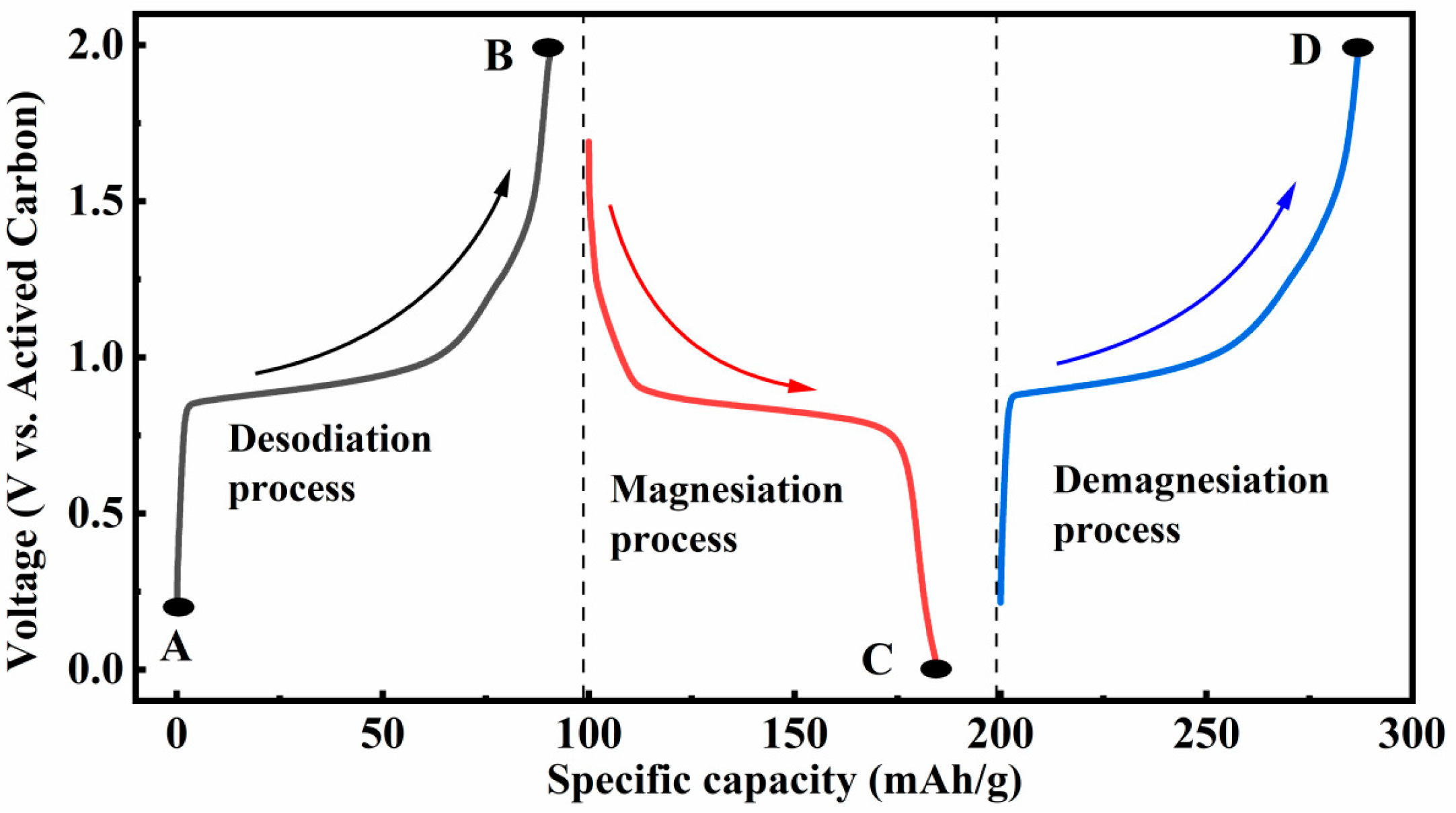
To clarify the magnesium storage reaction process of NVP@C, galvanostatic charge–discharge curves (Figure 4) and inductively coupled plasma optical emission spectroscopy (ICP-OES) quantitative analysis (Table 1) were combined to identify reaction stages. The results show that the magnesium storage process of NVP@C can be clearly divided into three sequential intercalation–deintercalation stages, with the material composition and ion migration behavior changing dynamically at each stage.
Figure 4.
Schematic diagram of the selection of test points in the galvanostatic charge–discharge curves of Na3V2(PO4)3@C. A is initial state. B is sodium-extracted state. C is magnesium-intercalated state. D is magnesium-deintercalated state.
Table 1.
Electrochemical composition and ICP-OES composition of Na3V2(PO4)3@C during charge and discharge processes.
Sodium extraction stage: initial state A to sodium-extracted state B: The material composition of initial state A is Na3.03V2(PO4)3, which is determined by ICP-OES. When charged to 2.0 V, Na+ is extracted from the Na2 sites of the NASICON framework. Na+ at Na1 sites is difficult to extract, so the sodium-extracted state B Mg0.03Na0.99V2(PO4)3 is formed. At this point, a small amount of Mg2+ 0.03 mol in the electrolyte is adsorbed on the material surface, and no obvious intercalation occurs.
Magnesium intercalation stage: sodium-extracted state B to magnesium-intercalated state C: When discharged to 0.01 V, Mg2+ is intercalated into the lattice vacancies after sodium extraction, forming the magnesium-intercalated state C Mg0.66Na0.91V2(PO4)3. The amount of magnesium intercalation is 0.63 mol.
Magnesium deintercalation stage: magnesium-intercalated state C to magnesium-deintercalated state D: When recharged to 2.0 V, Mg2+ is deintercalated from the lattice, forming the magnesium-deintercalated state D Mg0.04Na0.97V2(PO4)3. The amount of magnesium deintercalation is 0.62 mol. Meanwhile, a small amount of Na+ is re-intercalated. The framework partially recovers its initial structure but cannot be fully restored, leading to cyclic capacity fading.
The amount of sodium extraction is greater than that of magnesium intercalation, and the amount of magnesium intercalation is close to that of magnesium deintercalation. The pre-extraction of Na+ is a prerequisite for Mg2+ intercalation. In subsequent cycles, the participation of Na+ decreases, but the residual Na+ in the lattice still affects the diffusion of Mg2+. Based on the ICP-OES quantitative analysis results (Table 1), the discharge reaction (B to C) equation is as follows:
Mg0.03N0.99V2(PO4)3 + 0.63Mg2+ + 1.26e− → Mg0.66Na0.91V2(PO4)3 + 0.08Na+
3.3.2. Reaction Mechanism of NVP@C in Mg(TFSI)2/DME Electrolyte
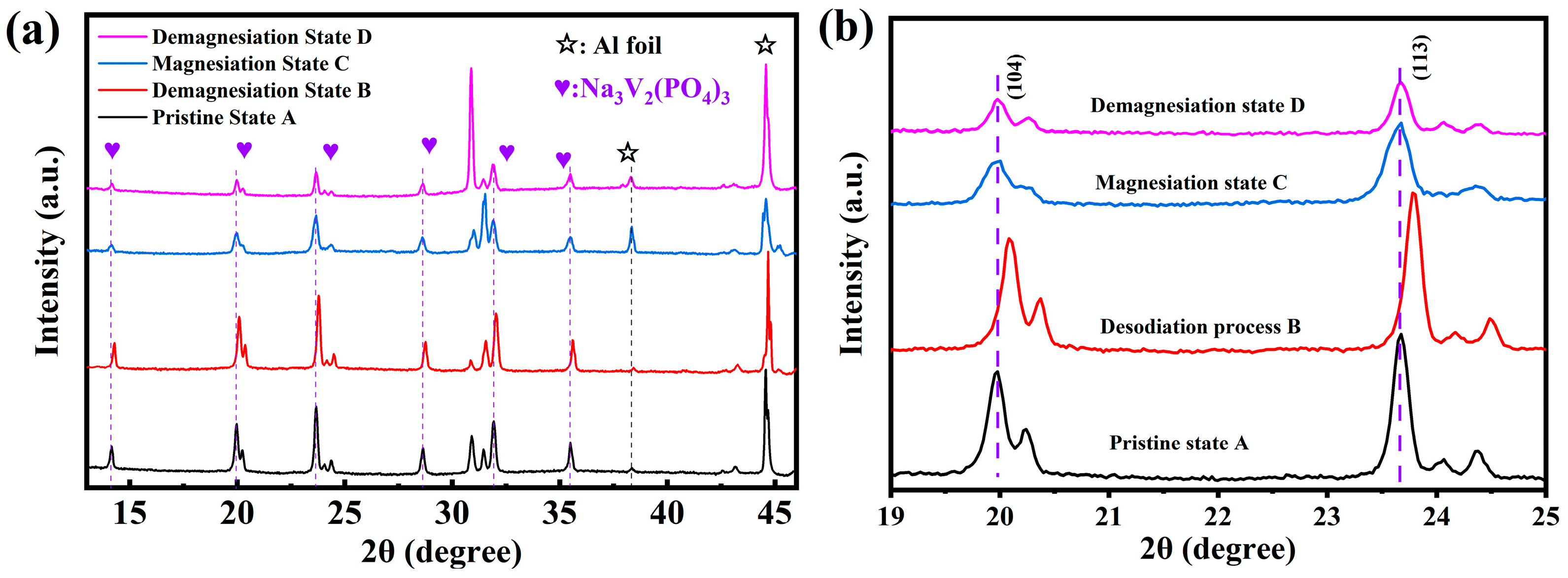
To determine the structural changes and phase transitions of the Na3V2(PO4)3@C cathode material during charge–discharge processes, ex situ XRD tests were conducted on the cathode materials in the four aforementioned charge–discharge states. Tests were performed in a 10–50° range, with results presented in Figure 5. Ex situ XRD tests reveal that during the A → B → C → D process of NVP@C, no new phases are associated with the (104) and (113) characteristic peaks and only shifts in diffraction angle occur. In the sodium extraction stage (A → B), the (104) peak shifts toward a higher diffraction angle, accompanied by lattice contraction. This lattice contraction is attributed to framework densification caused by Na+ extraction. In the magnesium intercalation stage (B → C), the (104) peak position shifts back toward a lower diffraction angle, leading to lattice expansion. This lattice expansion is caused by Mg2+ intercalation, but the peak position does not return to its initial state, as the extent of magnesium intercalation is less than that of sodium extraction. In the magnesium deintercalation stage (C → D), the peak position shifts further back, closely approaching its position in the initial state. This shift proves that lattice changes are reversible, with no irreversible phase transitions. Throughout the entire sodium extraction, magnesium intercalation, and magnesium deintercalation processes, the overall characteristic diffraction peaks do not disappear, and almost no new diffraction peaks form. These results indicate that few of the theoretically proposed intermediate phases (e.g., NaV2(PO4)3, MgNaV2(PO4)3) are generated. They also show that the sodium extraction, magnesium intercalation, and magnesium deintercalation processes do not alter the main structure of Na3V2(PO4)3@C. In summary, the electrochemical reaction process of NVP@C in Mg(TFSI)2/DME electrolyte is based on an intercalation–deintercalation mechanism and exhibits good reversibility. However, during this electrochemical reaction process, the intensity of each diffraction peak of the NVP@C cathode gradually decreases. This decrease in peak intensity indicates that the active material is continuously consumed during cycling, and the subsequent magnesium-ion intercalation–deintercalation reactions weaken continuously.
Figure 5.
Crystal structure changes of Na3V2(PO4)3@C in Mg(TFSI)2-based electrolyte: (a) ex situ XRD patterns under different states, (b) partial magnification images.
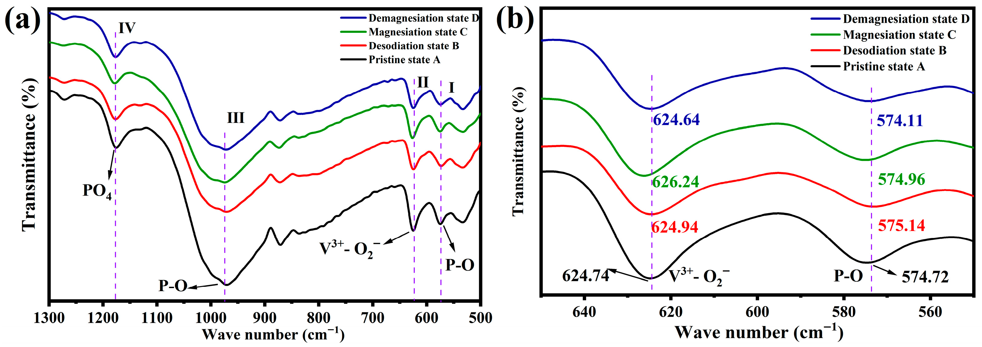
To analyze the molecular valence bonds, functional group vibrations, rotational energy level transitions, and reaction reversibility of Na3V2(PO4)3@C during sodium extraction, magnesium intercalation, and magnesium deintercalation, ex situ FTIR tests were conducted on the Na3V2(PO4)3@C materials in the aforementioned four charge–discharge states, as shown in Figure 6. Ex situ FTIR analysis confirms the reversibility of functional group changes. In the sodium extraction stage (A → B), the P-O stretching vibrations of PO4 tetrahedrons (970 cm−1, 1175 cm−1) and the V3+-O2− vibrations of VO6 octahedrons (624 cm−1) shift to higher wavenumbers. This shift is due to the oxidation of V3+ to V4+/V5+. During the magnesium intercalation/deintercalation stages (B → C → D), the aforementioned peak positions gradually return to their initial positions. This indicates that the PO4 and VO6 frameworks are stable with no irreversible bond breakage, which further verifies the intercalation–deintercalation reaction mechanism. Ex situ FTIR results show no irreversible breakage or reconstruction of the PO4 structure in NVP@C. During the magnesium storage reaction, the redox reaction between V3+ and V4+/V5+ is reversible, with no irreversible valence state trapping (e.g., V5+ cannot be reduced to V3+). Throughout the magnesium storage process, no new functional group vibration peaks (such as Mg-O-C, V-O-C) appear in the FTIR spectra. This reveals two points: ① No significant irreversible reactions occur between the electrolyte (Mg(TFSI)2/DME) and NVP@C, such as the esterification reaction between solvent DME and PO43−; and ② the formation of the CEI film—resulting from slight electrolyte decomposition—does not damage the chemical structure of the NVP@C bulk.
Figure 6.
Molecular structure changes of Na3V2(PO4)3@C in Mg(TFSI)2-based electrolyte: (a) ex situ FTIR spectra under different states, (b) partial magnification images. The wave numbers of different bonds have been labeled in the figure.
To investigate the specific reason for the deterioration of the magnesium storage performance of the Na3V2(PO4)3@C cathode material at a high current density of 500 mA/g in Mg(TFSI)2/DME electrolyte, electrochemical impedance spectroscopy (EIS) was used to test the cathode’s reaction kinetic characteristics. For the tests, a two-electrode system was used. The working electrode was Na3V2(PO4)3@C, while the reference and counter electrodes were both activated carbon coated on copper foil. EIS results under different cycle numbers were fitted using Zviewer software (version 3.1), as shown in Figure 7. Figure 7b shows a semicircle in the high-frequency region and a straight line in the low-frequency region. Based on this feature, the equivalent circuit diagram of the Na3V2(PO4)3@C cathode material under these experimental conditions was determined in Figure 7a. Among the parameters, Rs denotes the transfer resistance at the solid–liquid interface. Rct is the charge transfer resistance of the electrochemical reaction, corresponding to the radius of the high-frequency semicircle. Warburg impedance (W1) reflects the ion diffusion and migration ability, corresponding to the low-frequency straight line. CPE (constant phase element) is the capacitance at the interface between the positive and negative electrodes.
Figure 7.
Kinetic characteristics of Na3V2(PO4)3@C in Mg(TFSI)2/DME electrolyte: (a) equivalent circuit diagram for EIS tests, (b) EIS spectra after 50/100/500/1000 cycles at 500 mA/g.
Specific values from the EIS tests are shown in Table 2. After 1000 cycles, the Rct decreases continuously from 179.3 Ω to 47.55 Ω. This trend is attributed to the gradual activation of the amorphous carbon layer on the NVP@C surface during cycling, as well as the formation of a more uniform inorganic component (e.g., NaF, phosphate) in the cathode electrolyte interphase (CEI) film—both factors reduce charge transfer resistance and enhance electron migration capability, reflecting a secondary interface optimization effect []. However, Rs values increase slightly from 5.517 Ω to 6.338 Ω, while the Warburg impedance (W1, reflecting Mg2+ diffusion capability) fluctuates significantly from 216.2 Ω to 75.13 Ω, with no regular trend.
Table 2.
EIS spectrum fitting results of Na3V2(PO4)3@C in Mg(TFSI)2/DME electrolyte at high current density of 500 mA/g for 1000 cycles.
The diffusion and migration capability of Mg2+—expressed as diffusion coefficient D—is calculated using the following equation:
where R denotes the gas constant (8.314 J/(mol·K)), T represents the absolute temperature (273 K), and S is the cathode surface area (1.1304 cm2). n refers to the number of electrons transferred per mole of oxidation reaction. With V undergoing V3+ ↔ V4+/V5+ transition (2-electron transfer), n is set to 2. F is the Faraday constant (96,500 C/mol), and C is the Mg2+ concentration in the electrolyte (0.5 M). σ is the Warburg factor related to Z’. This factor is obtained by calculating the slope of the linear fit between the real part of impedance Z’ and ω−1/2. Here, ω is the angular frequency (ω = 2πf, f is the frequency corresponding to each data point in the EIS tests).
The variation of Mg2+ diffusion coefficient D calculated via Equation (1) is shown in Table 3. At a high current density of 500 mA/g, Mg2+ diffusion mobility in the Na3V2(PO4)3@C cathode is the lowest in the initial cycle. When the cycle number reaches around 1000, Mg2+ diffusion mobility is higher than that in the initial cycle, but its overall trend remains a gradual decrease. This result indicates that during charge–discharge at 500 mA/g, the electron transfer kinetics of the reaction in the Na3V2(PO4)3@C cathode does not weaken; instead, it shows a strengthening tendency. The Mg2+ diffusion issue is the main factor causing the deterioration of rate performance.
Table 3.
Mg2+ diffusion rate and σ value of Na3V2(PO4)3@C in Mg(TFSI)2/DME electrolyte at high current density of 500 mA/g after 1000 cycles.
Notably, the slight increase in Rs does not fully explain the severe performance degradation. The core reason lies in the gradual densification of the CEI film during cycling (rather than simple thickening): slight electrolyte decomposition leads to the continuous densification of the CEI film, which significantly increases the desolvation resistance of Mg2+ and the resistance of Mg2+ intercalation into the NVP@C lattice—this is directly reflected by the fluctuating W1 and the persistent polarization intensification in galvanostatic charge–discharge curves in Figure 3b []. In contrast, although Rct decreases (indicating improved charge transfer efficiency), magnesium-ion battery performance is dominated by ion diffusion rather than charge transfer. Thus, the optimized charge transfer cannot offset the performance loss caused by hindered Mg2+ diffusion.
4. Conclusions
In summary, this work prepared NVP@C cathode material via the sol–gel method and investigated its magnesium storage characteristics in 0.5 M Mg(TFSI)2/DME electrolyte. Results show that NVP@C exhibits a discharge voltage of 0.75 V vs. activated carbon (equivalent to 3.5 V vs. Mg/Mg2+), indicating a relatively high operating voltage. Its magnesium storage process is tentatively proposed to follow a three-stage intercalation–deintercalation mechanism of “sodium extraction—magnesium intercalation—magnesium deintercalation”, based on the current ICP-OES, ex situ XRD, and FTIR data. The above ex situ characterizations, together with the electrochemical results (e.g., stable CV peak shape, partial rate capacity recovery), collectively support a certain structural and chemical reversibility of NVP@C. Ex situ XRD results indicate no new phase formation, with a lattice parameter change rate < 0.5%. Ex situ FTIR results show reversible vibration peaks for PO4 and VO6 functional groups, as well as reversible valence state changes between V3+ and V4+/V5+—confirming excellent reversibility in NVP@C’s structure and chemical environment. The performance degradation of NVP@C is not caused by the increase in charge transfer impedance (Rct), but by the gradual densification of the CEI film during cycling, leading to increased Mg2+ diffusion resistance. Even if Rct decreases, it cannot reverse the capacity decay trend dominated by ion diffusion. In conclusion, NVP@C exhibits good magnesium storage reversibility, but its performance is limited by electrolyte transport efficiency and interface impedance. In future studies, further breakthroughs could be achieved through electrolyte modification or material interface modification (e.g., inorganic coating via Atomic Layer Deposition (ALD)), laying a foundation for the practical application of magnesium-ion batteries.
Author Contributions
Conceptualization, G.H. and J.W. (Jingfeng Wang); Methodology, J.W. (Jingfeng Wang); Investigation and formal analysis, P.Z. and J.Y.; Data curation, J.W. (Jaxu Wang) and X.M.; Writing—original draft preparation, P.Z.; Writing—review and editing, J.W. (Jingxing Wang); project administration, G.H. and J.W. (Jingfeng Wang). All authors have read and agreed to the published version of the manuscript.
Funding
This research was funded by the Chongqing Technology Innovation and Application Development Project (No. CSTB2022TIAD-KPX0028) and the Chongqing University Large-scale Instrument and Equipment Open Fund (No. Z20250311).
Data Availability Statement
The original contributions presented in this study are included in the article. Further inquiries can be directed to the corresponding authors.
Acknowledgments
The author expresses gratitude to the Electron Microscopy Center of Chongqing University and the Analytical Testing Center of Chongqing University for providing equipment support for material characterization in this study.
Conflicts of Interest
The authors declare no conflicts of interest.
References
- Liu, Q.; Hu, Z.; Chen, M.; Zou, C.; Jin, H.; Wang, S.; Chou, S.L.; Liu, Y.; Dou, S.X. The Cathode Choice for Commercialization of Sodium-Ion Batteries: Layered Transition Metal Oxides versus Prussian Blue Analogs. Adv. Funct. Mater. 2020, 30, 1909530. [Google Scholar] [CrossRef]
- Yoo, H.D.; Shterenberg, I.; Gofer, Y.; Gershinsky, G.; Pour, N.; Aurbach, D. Mg rechargeable batteries: An on-going challenge. Energy Environ. Sci. 2013, 6, 2265–2279. [Google Scholar] [CrossRef]
- Gregory, T.D.; Hoffman, R.J.; Winterton, R.C. Nonaqueous Electrochemistry of Magnesium—Applications to Energy-Storage. J. Electrochem. Soc. 1990, 137, 775–780. [Google Scholar] [CrossRef]
- Lu, Z.; Schechter, A.; Moshkovich, M.; Aurbach, D. On the electrochemical behavior of magnesium electrodes in polar aprotic electrolyte solutions. J. Electroanal. Chem. 1999, 466, 203–217. [Google Scholar] [CrossRef]
- Aurbach, D.; Lu, Z.; Schechter, A.; Gofer, Y.; Gizbar, H.; Turgeman, R.; Cohen, Y.; Moshkovich, M.; Levi, E. Prototype systems for rechargeable magnesium batteries. Nature 2000, 407, 724–727. [Google Scholar] [CrossRef]
- Zhang, Y.; Geng, H.; Wei, W.; Ma, J.; Chen, L.; Li, C.C. Challenges and recent progress in the design of advanced electrode materials for rechargeable Mg batteries. Energy Storage Mater. 2019, 20, 118–138. [Google Scholar] [CrossRef]
- Sun, C.; Wang, H.; Yang, F.; Tang, A.; Huang, G.; Li, L.; Wang, Z.; Qu, B.; Xu, C.; Tan, S.; et al. Layered buserite Mg-Mn oxide cathode for aqueous rechargeable Mg-ion battery. J. Magnes. Alloys 2023, 11, 840–850. [Google Scholar] [CrossRef]
- Wang, Q.; Liu, Z.Z.; Xu, T.; Li, H.J.; Chen, Y.G.; Yan, Y.G. High cycling stability of MnO2 cathode for aqueous Mg-ion batteries enabled by Fe doping. J. Power Sources 2024, 611, 9. [Google Scholar] [CrossRef]
- Choyal, V.; Dey, D.; Sai Gautam, G. Exploration of Amorphous V2O5 as Cathode for Magnesium Batteries. Small 2025, e05851. [Google Scholar] [CrossRef]
- Truong, Q.D.; Kempaiah Devaraju, M.; Nguyen, D.N.; Gambe, Y.; Nayuki, K.; Sasaki, Y.; Tran, P.D.; Honma, I. Disulfide-Bridged (Mo3S11) Cluster Polymer: Molecular Dynamics and Application as Electrode Material for a Rechargeable Magnesium Battery. Nano Lett. 2016, 16, 5829–5835. [Google Scholar] [CrossRef] [PubMed]
- Ren, W.; Xiong, F.; Fan, Y.; Xiong, Y.; Jian, Z. Hierarchical Copper Sulfide Porous Nanocages for Rechargeable Multivalent-Ion Batteries. ACS Appl. Mater. Interfaces 2020, 12, 10471–10478. [Google Scholar] [CrossRef]
- Fei, Y.; Wang, H.; Xu, Y.; Song, L.; Man, Y.; Du, Y.; Bao, J.; Zhou, X. Bimetallic sulfide CoNi2S4 hollow nanospheres as a high-performance cathode material for Mg-ion batteries. Chem. Eng. J. 2024, 480, 148255. [Google Scholar] [CrossRef]
- Wang, J.; Yang, G.; Ghosh, T.; Bai, Y.; Lim, C.Y.J.; Zhang, L.; Seng, D.H.L.; Goh, W.P.; Xing, Z.; Liu, Z.; et al. Hierarchical FeS2 cathode with suppressed shuttle effect for high performance magnesium-ion batteries. Nano Energy 2024, 119, 109082. [Google Scholar] [CrossRef]
- Truong, Q.D.; Devaraju, M.K.; Honma, I. Nanocrystalline MgMnSiO4 and MgCoSiO4 particles for rechargeable Mg-ion batteries. J. Power Sources 2017, 361, 195–202. [Google Scholar] [CrossRef]
- Perez-Vicente, C.; Rubio, S.; Ruiz, R.; Zuo, W.; Liang, Z.; Yang, Y.; Ortiz, G.F. Olivine-Type MgMn0.5 Zn0.5 SiO4 Cathode for Mg-Batteries: Experimental Studies and First Principles Calculations. Small 2023, 19, e2206010. [Google Scholar] [CrossRef] [PubMed]
- Xu, J.; Hong, Y.; Dou, S.; Wu, J.; Zhang, J.; Wang, Q.; Wen, T.; Song, Y.; Liu, W.D.; Zeng, J.; et al. Ultrafast Synthesis of Oxygen Vacancy-Rich MgFeSiO4 Cathode to Boost Diffusion Kinetics for Rechargeable Magnesium-Ion Batteries. Nano Lett. 2025, 25, 730–739. [Google Scholar] [CrossRef]
- Canepa, P.; Bo, S.H.; Sai Gautam, G.; Key, B.; Richards, W.D.; Shi, T.; Tian, Y.; Wang, Y.; Li, J.; Ceder, G. High magnesium mobility in ternary spinel chalcogenides. Nat. Commun. 2017, 8, 1759. [Google Scholar] [CrossRef]
- Medina, A.; Pérez-Vicente, C.; Alcántara, R. Spinel-type MgxMn2-yFeyO4 as a new electrode for sodium ion batteries. Electrochim. Acta 2022, 421, 140492. [Google Scholar] [CrossRef]
- Zhang, P.; Liu, T.; Miao, J.; Ning, W.; Sun, Y.; Qiu, F.; Shi, X.; Miao, S. Mg(Al, Fe, Mn, REE)2O4 Spinel Prepared from Pelagic REE-Rich Clays and Application as Magnesium-Ion-Battery Cathodes. ACS Appl. Mater. Interfaces 2024, 16, 60122–60131. [Google Scholar] [CrossRef]
- Mei, L.; Xu, J.; Wei, Z.; Liu, H.; Li, Y.; Ma, J.; Dou, S. Chevrel Phase Mo6 T8 (T = S, Se) as Electrodes for Advanced Energy Storage. Small 2017, 13, 1701441. [Google Scholar] [CrossRef]
- Sun, X.; Bonnick, P.; Nazar, L.F. Layered TiS2 Positive Electrode for Mg Batteries. ACS Energy Lett. 2016, 1, 297–301. [Google Scholar] [CrossRef]
- Yao, X.; Zhu, Z.; Li, Q.; Wang, X.; Xu, X.; Meng, J.; Ren, W.; Zhang, X.; Huang, Y.; Mai, L. 3.0 V High Energy Density Symmetric Sodium-Ion Battery: Na4V2(PO4)3||Na3V2(PO4)3. ACS Appl. Mater. Interfaces 2018, 10, 10022–10028. [Google Scholar] [CrossRef] [PubMed]
- Yang, Z.; Li, G.; Sun, J.; Xie, L.; Jiang, Y.; Huang, Y.; Chen, S. High performance cathode material based on Na3V2(PO4)2F3 and Na3V2(PO4)3 for sodium-ion batteries. Energy Storage Mater. 2020, 25, 724–730. [Google Scholar] [CrossRef]
- Zeng, X.; Peng, J.; Guo, Y.; Zhu, H.; Huang, X. Research Progress on Na3V2(PO4)3 Cathode Material of Sodium Ion Battery. Front. Chem. 2020, 8, 635. [Google Scholar] [CrossRef]
- Zhang, B.; Ma, K.; Lv, X.; Shi, K.; Wang, Y.; Nian, Z.; Li, Y.; Wang, L.; Dai, L.; He, Z. Recent advances of NASICON-Na3V2(PO4)3 as cathode for sodium-ion batteries: Synthesis, modifications, and perspectives. J. Alloys Compd. 2021, 867, 159060. [Google Scholar] [CrossRef]
- Zhang, H.; Wang, L.; Ma, L.; Liu, Y.; Hou, B.; Shang, N.; Zhang, S.; Song, J.; Chen, S.; Zhao, X. Surface Crystal Modification of Na3V2(PO4)3 to Cast Intermediate Na2V2(PO4)3 Phase toward High-Rate Sodium Storage. Adv. Sci. 2024, 11, e2306168. [Google Scholar] [CrossRef]
- Jian, Z.; Han, W.; Lu, X.; Yang, H.; Hu, Y.S.; Zhou, J.; Zhou, Z.; Li, J.; Chen, W.; Chen, D.; et al. Superior Electrochemical Performance and Storage Mechanism of Na3V2(PO4)3 Cathode for Room-Temperature Sodium-Ion Batteries. Adv. Energy Mater. 2012, 3, 156–160. [Google Scholar] [CrossRef]
- Jian, Z.; Yuan, C.; Han, W.; Lu, X.; Gu, L.; Xi, X.; Hu, Y.S.; Li, H.; Chen, W.; Chen, D.; et al. Atomic Structure and Kinetics of NASICON NaxV2(PO4)3 Cathode for Sodium-Ion Batteries. Adv. Funct. Mater. 2014, 24, 4265–4272. [Google Scholar] [CrossRef]
- Hu, J.; Li, X.; Liang, Q.; Xu, L.; Ding, C.; Liu, Y.; Gao, Y. Optimization Strategies of Na3V2(PO4)3 Cathode Materials for Sodium-Ion Batteries. Nano-Micro Lett. 2024, 17, 33. [Google Scholar] [CrossRef]
- Jiang, H.; Cai, X.; Wang, Z.; Zhang, L.; Zhou, L.; Lai, L.; Liu, X. Selection of graphene dopants for Na3V2(PO4)3 graphene composite as high rate, ultra long-life sodium-ion battery cathodes. Electrochim. Acta 2019, 306, 558–567. [Google Scholar] [CrossRef]
- Jiang, Y.; Yang, Z.; Li, W.; Zeng, L.; Pan, F.; Wang, M.; Wei, X.; Hu, G.; Gu, L.; Yu, Y. Nanoconfined Carbon-Coated Na3V2(PO4)3 Particles in Mesoporous Carbon Enabling Ultralong Cycle Life for Sodium-Ion Batteries. Adv. Energy Mater. 2015, 5, 1402104. [Google Scholar] [CrossRef]
- Liu, Q.; Meng, X.; Wei, Z.; Wang, D.; Gao, Y.; Wei, Y.; Du, F.; Chen, G. Core/Double-Shell Structured Na3V2(PO4)2F3@C Nanocomposite as the High Power and Long Lifespan Cathode for Sodium-Ion Batteries. ACS Appl. Mater. Interfaces 2016, 8, 31709–31715. [Google Scholar] [CrossRef]
- Rangasamy, V.S.; Thayumanasundaram, S.; Locquet, J.-P. Ionic liquid electrolytes based on sulfonium cation for lithium rechargeable batteries. Electrochim. Acta 2019, 328, 135133. [Google Scholar] [CrossRef]
- Novák, Z.; Kozma, G.; Kukovecz, Á. Electrolyte effect on the electroactuation behavior of multilayer polypyrrole films intercalated with TFSi−, ClO4−, NO3− anions in lithium and potassium based electrolyte solutions. J. Mol. Struct. 2022, 1262, 133057. [Google Scholar] [CrossRef]
- Jiang, X.; Liu, X.; Zeng, Z.; Xiao, L.; Ai, X.; Yang, H.; Cao, Y. A Nonflammable Na+-Based Dual-Carbon Battery with Low-Cost, High Voltage, and Long Cycle Life. Adv. Energy Mater. 2018, 8, 1802176. [Google Scholar] [CrossRef]
- Serra Moreno, J.; Armand, M.; Berman, M.B.; Greenbaum, S.G.; Scrosati, B.; Panero, S. Composite PEOn:NaTFSI polymer electrolyte: Preparation, thermal and electrochemical characterization. J. Power Sources 2014, 248, 695–702. [Google Scholar] [CrossRef]
- Wan, S.; Song, K.; Chen, J.; Zhao, S.; Ma, W.; Chen, W.; Chen, S. Reductive Competition Effect-Derived Solid Electrolyte Interphase with Evenly Scattered Inorganics Enabling Ultrahigh Rate and Long-Life Span Sodium Metal Batteries. J. Am. Chem. Soc. 2023, 145, 21661–21671. [Google Scholar] [CrossRef]
- Sun, J.; O’Dell, L.A.; Armand, M.; Howlett, P.C.; Forsyth, M. Anion-Derived Solid-Electrolyte Interphase Enables Long Life Na-Ion Batteries Using Superconcentrated Ionic Liquid Electrolytes. ACS Energy Lett. 2021, 6, 2481–2490. [Google Scholar] [CrossRef]
- Manohar, C.V.; Forsyth, M.; MacFarlane, D.R.; Mitra, S. Role of N-Propyl-N-Methyl Pyrrolidinium bis(trifluoromethanesulfonyl)imide as an Electrolyte Additive in Sodium Battery Electrochemistry. Energy Technol. 2018, 6, 2232–2237. [Google Scholar] [CrossRef]
- Zeng, J.; Yang, Y.; Lai, S.; Huang, J.; Zhang, Y.; Wang, J.; Zhao, J. A Promising High-Voltage Cathode Material Based on Mesoporous Na3V2(PO4)3/C for Rechargeable Magnesium Batteries. Chemistry 2017, 23, 16898–16905. [Google Scholar] [CrossRef]
- Ha, S.Y.; Lee, Y.W.; Woo, S.W.; Koo, B.; Kim, J.S.; Cho, J.; Lee, K.T.; Choi, N.S. Magnesium(II) bis(trifluoromethane sulfonyl) imide-based electrolytes with wide electrochemical windows for rechargeable magnesium batteries. ACS Appl. Mater. Interfaces 2014, 6, 4063–4073. [Google Scholar] [CrossRef]
- Yang, J.; Liu, Y.; Ye, J.; Wen, J.; Wang, J.; Huang, G.; Wang, J. A High Voltage Magnesium Ion Battery Based on Na3V2(PO4)3@C Cathode and Bi Nanowire Anode. Langmuir 2025, 41, 18919–18928. [Google Scholar] [CrossRef]
- Deng, Y.J.; Li, G.Y.; Deng, R.R.; Zhang, B.W.; Cao, L.Y.; Huang, G.S.; Wang, J.F.; Pan, F.S. Dual-Site Modulation of Mg2+ Desolvation Beyond the Primary Solvation Shell in Magnesium Battery Electrolytes. Angew. Chem.-Int. Edit. 2025, 64, 7. [Google Scholar] [CrossRef] [PubMed]
- Yan, B.G.; Karuppiah, C.; Walle, K.Z.; Abdelaal, M.M.; Kotobuki, M.; Lu, L. Review on dendrite formation of Mg metal anode and its prevention. Nano Energy 2024, 131, 16. [Google Scholar] [CrossRef]
- Guan, Q.H.; Zhuang, Q.; Xu, W.L.; Zhang, Y.Z.; Cheng, S.; Zhang, J.; Liu, M.N.; Lin, H.Z.; Wang, J. Accelerated Kinetics of Desolvation and Redox Transformation Enabled by MOF Sieving for High-Loading Mg-S Battery. Adv. Funct. Mater. 2025, 35, 2506397. [Google Scholar] [CrossRef]
- Ihsan-Ul-Haq, M.; Cui, J.; Mubarak, N.; Xu, M.Y.; Shen, X.; Luo, Z.T.; Huang, B.L.; Kim, J.K. Revealing Cathode-Electrolyte Interface on Flower-Shaped Na3V2(PO4)3/C Cathode through Cryogenic Electron Microscopy. Adv. Energy Sustain. Res. 2021, 2, 8. [Google Scholar] [CrossRef]
Disclaimer/Publisher’s Note: The statements, opinions and data contained in all publications are solely those of the individual author(s) and contributor(s) and not of MDPI and/or the editor(s). MDPI and/or the editor(s) disclaim responsibility for any injury to people or property resulting from any ideas, methods, instructions or products referred to in the content. |
© 2025 by the authors. Licensee MDPI, Basel, Switzerland. This article is an open access article distributed under the terms and conditions of the Creative Commons Attribution (CC BY) license (https://creativecommons.org/licenses/by/4.0/).