Abstract
The growing demand for renewable energy requires efficient technologies to maximize solar resource utilization. This study presents the development and validation of a novel dual-axis solar tracking system that integrates kinematic modeling, embedded control, and a monocular vision algorithm. Unlike fixed photovoltaic systems, the proposed design dynamically aligns solar panels with the sun’s position using a Denavit–Hartenberg-based model and real-time image analysis. The system was experimentally validated in the Isthmus of Tehuantepec, Mexico, a high-irradiance region. Results showed reliable sensor calibration with errors below 3%, and an 18% increase in energy capture compared to a fixed panel system. The prototype achieved a maximum output of 800 W using four 205 Wp modules. This work contributes an innovative, replicable approach to enhance solar energy harvesting under real operating conditions.
1. Introduction
The transition toward a sustainable energy model represents one of the main challenges of the twenty-first century [1,2,3]. The intensive use of fossil fuels has significantly contributed to climate change, environmental degradation, and biodiversity loss, while also undermining global energy security due to dependence on non-renewable resources subject to geopolitical fluctuations [4,5,6]. In this context, renewable energy sources, and particularly photovoltaic solar energy, have emerged as fundamental alternatives to achieving international sustainability goals, owing to their global availability, technological scalability, and low environmental impact [7,8,9,10,11].
In response to this challenge, international organizations such as the International Energy Agency (IEA) [12] and the Intergovernmental Panel on Climate Change (IPCC) [13] have urged the acceleration of decarbonization through the large-scale deployment of renewable energy sources. Public and private policies are increasingly aligned to promote clean and resilient technologies, which has resulted in sustained growth in electricity generation from non-conventional sources. As illustrated in Figure 1, derived from data published by the IEA in the World Energy Outlook 2023 [12], renewables accounted for approximately 30% of global electricity generation by 2022. Moreover, projections under the Net Zero Emissions by 2050 Scenario (NZE) estimate that this share will increase to 45.6% by 2030. This structural shift in the global energy mix confirms the technical viability of renewables as a cornerstone of the energy transition [14].
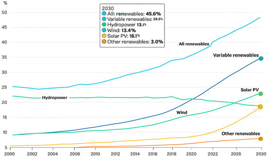
Figure 1.
Projected global share of renewable energy in electricity generation by source from 2000 to 2030. The figure includes historical data and projections for 2030 based on the International Energy Agency’s report World Energy Outlook 2023 [12]. The 2030 estimates are taken from the Net Zero Emissions by 2050 Scenario (NZE) and reflect current policy trends and technology adoption forecasts. The source data was adapted and redrawn for clarity.
Moreover, the most recent data show an accelerated growth in installed renewable energy capacity, reinforcing its leading role in modern power systems. As evidenced in Figure 2, by 2024, the global renewable generation capacity increased by 15.1% compared to the previous year, with solar energy contributing more than 70% of the total addition [14]. This unprecedented rate of expansion is partly due to technological innovations that have reduced installation and operation costs, as well as energy policies that prioritize the electrification of productive sectors and the diversification of sources.
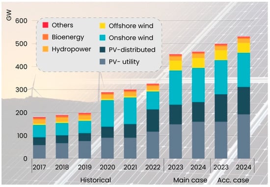
Figure 2.
Estimated distribution of installed renewable sources by 2024: hydropower, wind (onshore/offshore), distributed solar, utility-scale solar, and biomass.
Despite these global advances, technical and logistical challenges remain in optimizing solar energy utilization [15,16,17,18], particularly in regions with limited infrastructure or specific geographical conditions. Fixed photovoltaic systems, widely used in domestic and rural installations, present inherent limitations associated with their static panel orientation, which prevents them from optimally capturing solar radiation throughout the sun’s daily path. To overcome this drawback, solar tracking systems have been developed to continuously align panels with the sun’s position, significantly increasing the captured energy [19,20,21,22,23]. Recent studies have shown that dual-axis systems can improve conversion efficiency by up to 28% compared to fixed systems and by up to 12% compared to single-axis trackers [24,25,26]. These advances have been further enhanced by emerging technologies such as predictive algorithms, computer vision, intelligent controllers, and artificial intelligence methods, which have expanded the adaptability, precision, and operational efficiency of solar tracking systems.
In the industrial domain, companies such as Nextracker have spearheaded the development of commercial solutions that integrate artificial intelligence and topographic adaptability. These systems reduce the levelized cost of electricity and increase resilience to variable climatic conditions [27].
In parallel, the scientific literature has reported a growing incorporation of kinematic modeling techniques, embedded control, and performance analysis across diverse contexts [28,29,30,31,32]. However, most of these studies have been conducted in regions with high technological investment, while their applicability in local or resource-limited environments remains incipient.
In Mexico, solar resources are abundant across most of the national territory; however, the adoption of solar tracking technologies remains limited, particularly in rural areas or regions with scarce infrastructure. Several studies have reported energy capture improvements with single- or dual-axis tracking systems compared to fixed structures, generally ranging from 20% to 45%, depending on latitude, irradiance, and specific climatic conditions. These improvements are most notable during the early morning hours and late afternoon, when fixed panels fail to optimally face the sun [33,34].
In this context, the Isthmus of Tehuantepec, located in the state of Oaxaca, represents a strategic area for solar energy harvesting due to its high annual irradiation. Despite this potential, the efficiency of solar utilization remains limited because of the prevalence of fixed photovoltaic installations, particularly in rural communities. This situation highlights the need for technically efficient and adaptable solutions that enhance photovoltaic performance under real operating conditions.
This article presents the design, modeling, instrumentation, and control of a dual-axis solar tracking system based on the kinematics of a robotic manipulator and operated through a computer vision algorithm. This study differs from previous works by integrating robotic kinematic modeling through the Denavit–Hartenberg convention with an embedded control architecture and a monocular vision algorithm for real-time solar tracking. The experimental validation conducted under the irradiance conditions of the Isthmus of Tehuantepec, Oaxaca, Mexico, demonstrated the technical feasibility and performance improvement of the proposed approach. While the system was tested in a region with high solar potential, this research focuses exclusively on the technical aspects of performance and does not include an economic or scalability analysis, which should be addressed in future work. The distinct contribution of this work is the experimental integration of Denavit–Hartenberg kinematic modeling with an embedded controller guided by a monocular vision algorithm, and its field validation under real operating conditions in the Isthmus of Tehuantepec. Based on the surveyed literature and our comparative analysis, we did not find prior dual-axis implementations that combine these elements and report a side-by-side performance gain against a co-located fixed array. Overall, the results confirm the system’s capacity to improve solar radiation capture and energy efficiency, contributing to the broader development of clean and sustainable energy technologies in high-irradiance regions of Mexico.
Table 1 presents a comparative summary of the most relevant dual-axis solar tracking studies, encompassing experimental, analytical, and review-based works published between 2013 and 2025. Most reported designs employ photoelectric or ephemeris-based sensing combined with PID or heuristic control, achieving energy gains ranging from 7% to 32.25% over fixed photovoltaic systems. Only a few studies quantify precision explicitly [31] report a maximum pointing error below 0.4°, while [28] highlight a predictive AI-based control with an accuracy of ±0.5°, confirming the importance of closed-loop and intelligent tracking strategies. Regarding efficiency, refs. [26,30] demonstrated the highest experimental improvements, with 32.25% and 24.6% energy increases, respectively, validating the impact of dual-axis motion in maximizing irradiance capture. In contrast, ref. [34] remain among the few to report the energy consumption of the tracker itself, 1.5 Wh/day, equivalent to just 1.36% of the net energy gain, underscoring the relevance of power-efficient designs. Economic feasibility has also been scarcely addressed, with [30] study showing a 1.48-year reduction in payback period compared to fixed systems.

Table 1.
Comparative Table of Dual-Axis Solar Tracking Studies.
In comparison, the prototype developed in this study introduces a novel embedded vision-based architecture, integrating a monocular camera and optional IMU for autonomous solar tracking. This approach minimizes mechanical complexity and external sensing components, while maintaining sub-degree accuracy through geometric error correction and low-latency PID/MPC control. Unlike previous systems relying on LDR arrays or ephemeris calculations, the proposed solution demonstrates a high degree of reliability and precision, positioning it as a lightweight and scalable alternative for small- and medium-scale photovoltaic applications.
2. Materials and Methods
The development of the solar tracking system was structured in three main phases: (1) kinematic modeling of the two-degree-of-freedom system using the Denavit–Hartenberg convention; (2) instrumentation and integration of the electronic and control components; and (3) experimental validation. The following sections provide a detailed description of the materials employed and the methodology applied for the design, implementation, and testing of the system (Figure 3).
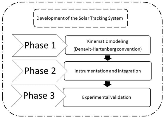
Figure 3.
General scheme of the methodology followed for the development of the solar tracking system, structured in three phases.
The system integrates a dual-axis control loop supported by a Denavit–Hartenberg (D–H) kinematic model, actuated through PWM and I2C communication, and feedbacked by a monocular vision algorithm that estimates the pointing error on the image plane. This configuration eliminates dependence on photoelectric sensors or astronomical algorithms, reducing the number of components and potential failure points while maintaining high tracking precision.
2.1. Phase 1: Kinematic Modeling of the Two-Degree-of-Freedom System Using the Denavit–Hartenberg Convention
The solar tracking system was conceived as a robotic manipulator with two degrees of freedom, consisting of an azimuthal (horizontal) rotation axis and a zenithal (vertical) rotation axis. This configuration allows the photovoltaic panel plane to be oriented according to the solar trajectory, thereby maximizing irradiance capture compared to fixed systems.
To mathematically describe the kinematics of the system, the Denavit–Hartenberg (D–H) convention [35], widely used in robotics to represent homogeneous transformations between consecutive reference frames [36,37], was employed. This convention is based on four fundamental parameters: link length (a), link twist (α), joint offset (d) and joint angle (θ). With these parameters, it is possible to formulate transformation matrices that describe the position and orientation of each link with respect to the previous one.
In this work, the solar tracker was modeled as a two-link system with two rotational joints. The first link corresponds to the azimuthal motion, which orients the panel in the horizontal plane, while the second provides elevation or tilt in the vertical plane. Thus, the orientation of the panel with respect to the base reference frame is obtained through the product of homogeneous transformation matrices, leading to the forward kinematic model. Conversely, inverse kinematics was used to calculate the joint angles θ1 and θ2 that orient the panel toward the desired solar position.
The kinematic analysis is developed from the definition of the joint variable qi, which may correspond to a rotation angle or a linear displacement depending on the nature of the joint, as expressed in Equation (1):
For each link, a local coordinate system (oi, xi, yi, zi), was assigned, ensuring that the coordinates of each point remain invariant when expressed in its own frame. Figure 4 shows the reference frames assigned to the proposed manipulator.
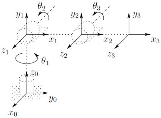
Figure 4.
Coordinate frames assigned to the elbow manipulator.
The position and orientation of each local frame with respect to the previous one are described by the homogeneous transformation matrix Ai, which depends on the joint variable qi (Equation (2)):
In general, the relationship between two frames i and j is expressed by the matrix (Equation (3)):
The global homogeneous transformation, which includes both the orientation and the position of frame n relative to the base frame 0, is represented in matrix form by combining two key components: , the rotation matrix that describes the orientation, and , the position vector that defines the location of the origin of frame n with respect to frame 0. These elements are structured as shown in Equations (4) and (5).
Each homogeneous transformation takes the form shown in Equation (6):
This leads to the general representation Equation (7):
The orientation of the frames is obtained from Equation (8),
And the position of the vectors is expressed as Equation (9):
The functional representation of the system was obtained by applying the D–H convention [36], which allows each homogeneous transformation to be expressed as the product of four elementary transformations: a rotation and a translation along the z-axis, followed by a translation and a rotation along the x-axis (Equation (10)):
These elementary transformations are expressed as follows (Equations (11)–(14)):
This results in the general form of the transformation matrix (Equation (15)):
Figure 5 illustrates the sign convention adopted for the angles and .
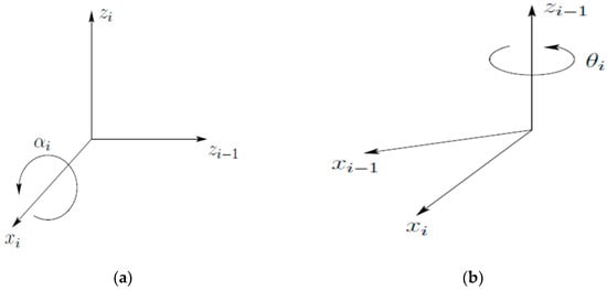
Figure 5.
Sign convention adopted for the angles: (a) angle ; (b) angle
In order to systematically structure the functional representation of the robotic manipulator, the nine methodological steps described below were followed:
- Step 1:
- Locate and label the joint axes .
- Step 2:
- Establish the base frame at any convenient point along the axis. The axes and are chosen to form a right-handed coordinate system.For i = 1 …, n − 1, perform Steps 3 to 5.
- Step 3:
- Place the origin at the intersection of with the common normal to and . If intersects set at this intersection. If and are parallel, locate at any convenient point along .
- Step 4:
- Assign along the common normal between and through , or in the direction normal to the plane defined by if the axes intersect y .
- Step 5:
- Define to complete the right-handed frame.
- Step 6:
- Establish the end-effector frame on, xn, yn, zn. If the nth joint is revolute, align with the direction of . Place the origin conveniently along preferably at the gripper’s center or at the tip of the tool attached to the manipulator. Define along the gripper closing direction and set = . If the tool is not a simple gripper, assign and conveniently to form a right-handed frame.
- Step 7:
- Construct the link parameter table with , where:
- Step 8:
- Form the homogeneous transformation matrices by substituting the parameters defined above.
- Step 9:
- Compute the overall transformation , which yields the position and orientation of the tool frame expressed in base coordinates.
The fulfillment of these steps ensured the precise mathematical representation of the manipulator, guaranteeing that the proposed system could accurately reproduce the solar trajectory under real operating conditions. This modeling constituted the fundamental basis for the design of the control system, which is described in the following phase.
2.2. Phase 2: Instrumentation and Integration of Electronic and Control Components
The second phase of the development involved electronic instrumentation as well as mechanical and control integration, with the objective of implementing a functional prototype of the dual-axis solar tracking system. This stage encompassed both the physical components (photovoltaic panels, mechanical structure, sensors, and actuators) and the embedded control system responsible for executing the tracking algorithm.
The system was designed to operate four Kyocera photovoltaic panels, model KD205GX-LP, each rated at 205 Wp, selected for their commercial availability and suitability for the irradiance conditions of the Isthmus of Tehuantepec. The supporting structure was modeled in CAD using low-cost materials with high weather resistance, ensuring rigidity and durability. Figure 6 presents four views of the CAD design of the dual-axis photovoltaic tracking system. The structure consists of a fixed frame and two movable links that enable azimuthal and zenithal motion, driven by a system of gears and mechanical couplings that provide stability and minimize backlash losses. The front view (Figure 6a) displays the main dimensions of the supporting frame and the overall system height, while the side view (Figure 6b) illustrates the zenithal tilting mechanism and its angular range of motion. The top view (Figure 6c) shows the distribution of the photovoltaic modules and the total width of the array, and finally, the isometric view (Figure 6d) provides an overall perspective of the assembly, highlighting the final configuration of the panels and the supporting structure.
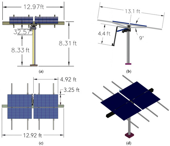
Figure 6.
Dual-axis photovoltaic tracking system: (a) front view of the supporting structure and system height; (b) side view; (c) top view; (d) isometric view.
For measuring the current generated by the photovoltaic panels, the ACS712 Hall-effect sensor was employed, which is widely used in instrumentation applications due to its low cost and acceptable accuracy. This device operates with a 5.0 V single supply operation and provides a reference voltage of 2.5 V when the current is 0 A, from which the output signal increases or decreases linearly according to the measured current. The sensor sensitivity ranges from 66 to 185 mV/A (output sensitivity), depending on the operating conditions. In this work, the ACS712-30A version was used, with a sensitivity of 100 mV/A, which provides adequate resolution for the currents generated by the photovoltaic system [38]. Based on Ohm’s law, the sensor is characterized; the manufacturer provides an equation representing the relationship between the output voltage (V) and the measured current (I), which is expressed as Equation (16), specific to the sensor.
where:
V = Voltage (V)
l = Current (A)
m = Sensitivity = 100 (mV/A).
Thus, the current can be obtained by rearranging as shown in Equation (17):
Complementarily, for the measurement of the panel voltage, a voltage divider was implemented in order to adapt the signal to the input range of the microcontroller’s analog pins. This circuit distributes the input voltage among resistors connected in series, allowing it to be proportionally reduced. To calculate the voltage induced in each resistor, Ohm’s Law was applied (Equation (18)):
where:
V = Voltage (V)
I = Current (A)
R= Resistance (Ω)
Considering the resistor values and the input voltage Vin, the output voltage across a specific resistor Rx can be expressed as shown in Equation (19):
Figure 7 shows the implemented scheme integrating the current sensor and the voltage divider for the measurement of the output voltage and current of the photovoltaic panels. The circuit consists of three resistors connected in series (), where the reduced signal is taken across and connected to the analog input of the Arduino Mega 2560 (0 a 5 V) (Arduino LLC, Somerville, MA, USA). This configuration enabled scaling of the voltage values generated by the photovoltaic panel, ensuring they remained within the operating range of the microcontroller (0–5 V).
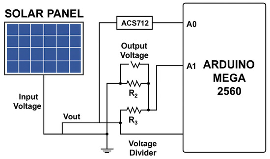
Figure 7.
Electrical schematic of the data acquisition system. The diagram shows the connection of the photovoltaic panel with the voltage divider and the ACS712 current sensor, whose outputs are connected to the Arduino Mega 2560 analog inputs A0 and A1, respectively.
The measured current and voltage were used both to validate the behavior of the system and to subsequently compare the performance between the fixed panel and the solar tracking panel. The control system was implemented on an Arduino Mega 2560 microcontroller, selected for its processing capacity, number of digital and analog inputs/outputs, and compatibility with open-source programming libraries. It was programmed in C++ using OpenCV libraries. The Arduino board received the signals from the voltage divider and the ACS712 current sensor, while simultaneously executing the real-time solar tracking algorithm.
The control algorithm was based on the previously described two-degree-of-freedom kinematic model, calculating the orientation angles θ1 and θ2 to position the solar panels according to the sun’s trajectory. For the actuation of medium-power DC motors, two MD03 controllers were employed, capable of handling 24 V and driven through pulse-width modulation (PWM) at 7.8 kHz. These controllers communicated with the Arduino Mega via the I2C protocol, using a 5 V supply for logic control and an FSP300-60ATV power source to operate the motors at 24 V. This integration ensured precise and reliable control of the system under real operating conditions.
In addition, a monocular vision algorithm was incorporated to improve tracking accuracy through image analysis. An endoscopic camera with a resolution of 640 × 480 pixels, a diameter of 7 mm, a 67° field of view, and outdoor resistance was installed at the top-center of the photovoltaic array at a 90° angle relative to the sun’s path (Figure 8a). The camera captured images that were digitized and processed on an auxiliary computer, transforming visual information into solar position data.
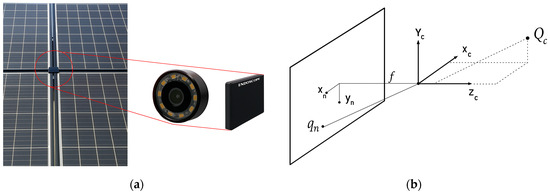
Figure 8.
Implementation of the camera for the monocular vision algorithm: (a) endoscopic camera with 640 × 480 pixels, 7 mm diameter, 67° field of view, and weather resistance, installed at the top-center of the photovoltaic array at a 90° angle relative to the sun’s path; (b) projection scheme relating a point in three-dimensional space to its two-dimensional projection on the camera image plane.
The relationship between the three-dimensional environment and the two-dimensional projection on the camera image plane is illustrated in Figure 8b. In this model, the point represents the origin of the camera’s coordinate system; the point corresponds to a point in three-dimensional space whose projection on the image plane is defined as . The parameter denotes the focal length of the camera, which is a key factor for the geometric reconstruction of the solar position.
The integration of the embedded control system with the monocular vision algorithm enabled the combination of sensor feedback with real-time optical processing, resulting in a solar tracking system that is more robust, precise, and adaptable to environmental variations. This synergy between electronics, control, and computer vision consolidated the instrumentation stage of the prototype, providing a solid foundation for its experimental validation under real operating conditions.
2.3. Phase 3: Experimental Validation
The experimental validation of the solar tracking system was conducted in the Isthmus of Tehuantepec, Oaxaca, Mexico, one of the regions with the greatest potential for solar energy utilization nationwide. Mexico receives an average daily solar irradiation of approximately 5.5 kWh/m2, placing it among the most favorable regions globally for solar resource availability [39]. Figure 9 illustrates the spatial distribution of solar radiation in Mexico (Figure 9a) and in the state of Oaxaca (Figure 9b), highlighting that the Isthmus of Tehuantepec records the highest levels of solar irradiation.
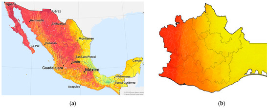
Figure 9.
Solar radiation map: (a) distribution of solar radiation in Mexico [40], highlighting the national average of 5.5 kWh/m2/day; (b) solar radiation in the state of Oaxaca, where the Isthmus of Tehuantepec shows the highest values.
The validation site is located at the geographic coordinates 16°17′19.499″ N, 95°14′27.135″ W, which provided optimal conditions for evaluating the system’s performance. Based on this location, the solar trajectory was calculated, as shown in Figure 10, where the variations in solar altitude recorded during the measurement period are illustrated.
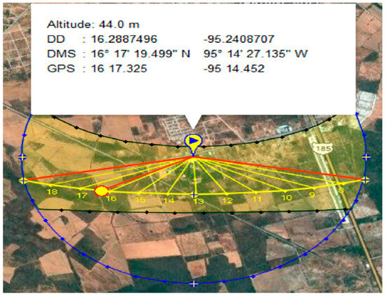
Figure 10.
Solar trajectory at the experimental site. The geographic coordinates of the location (16°17′19.499″ N, 95°14′27.135″ W) and the projection of solar altitude throughout the day are shown, used as a reference for the experimental validation of the tracking system.
The experimental setup consisted of installing the dual-axis solar tracking prototype on a fixed base, located in an open field and oriented according to local irradiance conditions. To enable a controlled comparison, a photovoltaic panel with fixed orientation was also installed under the same environmental conditions and connected to an equivalent data acquisition system. This arrangement allowed for the simultaneous evaluation of the proposed system’s performance against a conventional fixed array.
According to NASA POWER data, the city of Santo Domingo Tehuantepec recorded an average solar irradiation of 5.64 kWh/m2·day in 2024, reaching a maximum of 6.54 kWh/m2·day in April and a minimum of 4.80 kWh/m2·day in November [41]. These updated values reinforce the suitability of the site for the experimental validation. Additionally, the Peak Sun Hour (PSH) was analyzed as a reference indicator for daily irradiation. PSH is defined as the number of hours during which the irradiance equals 1000 W/m2, the standard test condition for photovoltaic systems. Mathematically, it is equivalent to the daily irradiation divided by 1 kW/m2. Figure 11 shows the monthly behavior of PSH in Santo Domingo Tehuantepec during 2024, with a minimum value of 4.48 h in November and a maximum of 6.54 h in April. These results confirm the high solar potential of the region for photovoltaic applications.
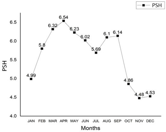
Figure 11.
Monthly behavior of Peak Sun Hours (PSH) in Santo Domingo Tehuantepec, Oaxaca, Mexico, during 2024. A minimum value of 4.48 h is observed in November and a maximum of 6.54 h in April, confirming the high availability of the solar resource in the region for photovoltaic applications.
The optimal tilt angle of the reference fixed solar panel was established based on the well-known empirical relationship in solar energy design, which suggests that the optimal inclination angle (β) for a fixed, south-facing panel in the Northern Hemisphere is approximately equal to the site’s latitude (φ). These show that aligning the panel tilt with the latitude maximizes annual solar irradiance capture under average conditions [42,43]. Formally, this approximation is expressed by Equation (20):
where:
- where n is a small seasonal correction factor. For the purposes of this study, and given the geographic coordinates of the experimental site in Santo Domingo Tehuantepec, Oaxaca (16°17′19.499″ N), the site latitude is approximately φ ≈ 16.29°. Therefore, the optimal fixed tilt angle was set as β ≈ φ, applying Equation (20) without seasonal adjustment to reflect local conditions. The measurement system was integrated with the embedded sensors previously described, whose signals were processed by the Arduino Mega 2560 board, as shown in Figure 12. In parallel, external instruments such as digital multimeters and a data logger were used to validate the values obtained by the microcontroller and to ensure the reliability of the records. The system was programmed to acquire data at one-minute intervals during continuous 24 h sessions.
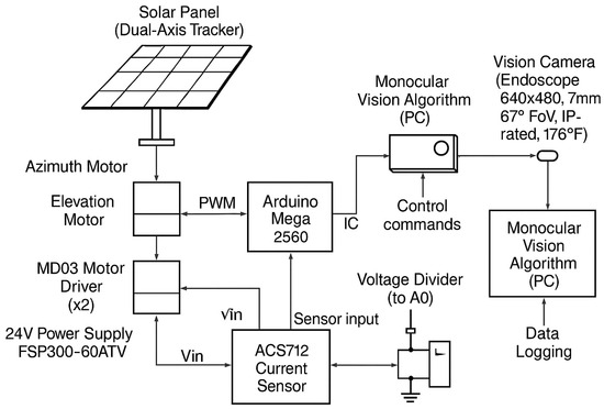 Figure 12. General schematic of the dual-axis solar tracking system.
During validation, current, voltage, and instantaneous power values were recorded simultaneously in both systems (fixed and tracking). Based on these data, energy performance indicators were calculated, including average power, maximum power, and accumulated energy (Wh) generated each day.
As a comparative metric, the relative efficiency of the tracking system with respect to the fixed panel was defined, expressed as the ratio between the accumulated energy in each configuration. This relation allowed the calculation of the percentage increase in solar energy utilization achieved with the dual-axis system, providing experimental evidence of the effectiveness of the kinematic model, the embedded controller, and the monocular vision algorithm integrated into the prototype.
3. Results
3.1. Functional Representation of the Kinematic Model of the Two-Degree-of-Freedom System Using the D–H Convention
As a direct outcome of the kinematic formulation presented in Section 2.1, the mathematical model developed through the Denavit–Hartenberg (D–H) convention was implemented to obtain the functional representation of the two-degree-of-freedom system. This representation constitutes a result of the simulation process used to verify the internal consistency of the model and to visualize the system’s geometric behavior during a typical solar trajectory at the experimental site.
By applying the D–H parameters derived in the methodology, the manipulator configuration was defined and represented in Figure 13, where the azimuthal and zenithal motions correspond to the first and second rotational axes, respectively. The resulting transformation matrices (Equations (21)–(23)) describe the real-time spatial orientation of the photovoltaic array as a function of the joint angles θ1 and θ2, thus confirming the validity of the D–H formulation for the solar tracking mechanism.
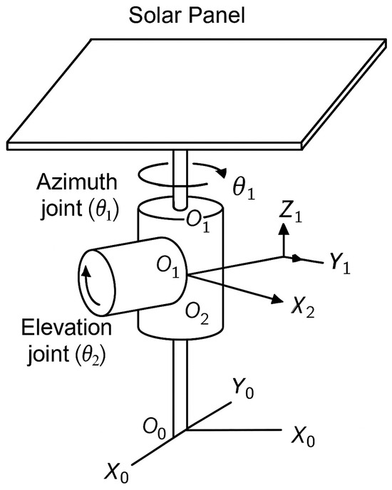
Figure 13.
Functional representation of the solar tracking system as a two-degree-of-freedom robotic manipulator.
Based on the Denavit–Hartenberg (D–H) convention procedure, the parameter table of the links for the two-degree-of-freedom system was constructed, as shown in Table 2.
Table 2.
parameters of a two-degree-of-freedom robotic manipulator.
Regarding the position and orientation of the end effector, i.e., the solar panels, the parameters were substituted into the homogeneous transformation matrices, yielding Equations (21) and (22), namely and , respectively.
The resulting transformation matrix is obtained by multiplying the two homogeneous transformation matrices, such that , as expressed in Equation (23):
which allowed us to describe the position and orientation of the end-effector as a function of the joint angles θ1 and θ2 corresponding to each articulation.
3.2. Instrumentation Tests and Integration of Electronic and Control Components
Following the modeling and control design stages, experimental tests were carried out to validate the instrumentation and control integration of the prototype. These tests represent the practical implementation results of the methodology described in Section 2.3, focusing on verifying sensor accuracy, controller reliability, and the stability of the embedded system under continuous operation (Figure 14).
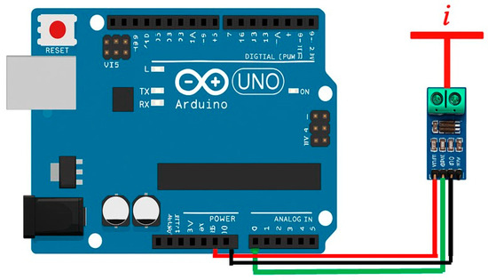
Figure 14.
Connection scheme of the ACS712 current sensor with the Arduino board for real-time data acquisition. The sensor delivers an analog signal proportional to the measured current, which is processed by the microcontroller for further analysis.
The calibration of the ACS712 current sensor and the voltage divider yielded linear responses with relative errors below 3%, as shown in Figure 15 and Figure 16. Similarly, the performance characterization of the MD03 motor controllers (Figure 17) demonstrated linear speed control with minimal thermal dissipation, confirming the robustness of the system for real-time solar tracking applications.
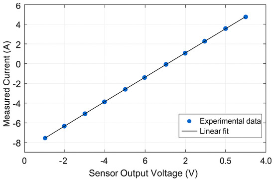
Figure 15.
Relationship between the measured current and the output voltage of the ACS712 sensor.
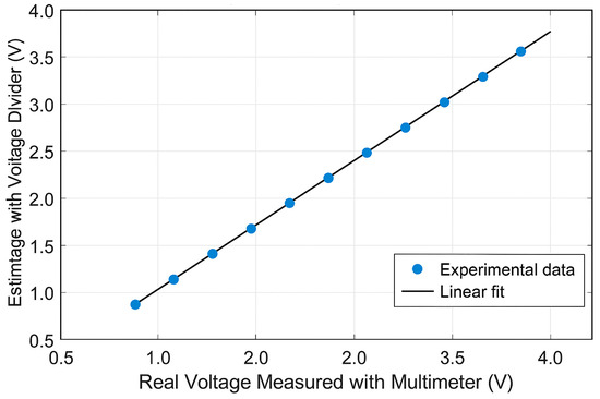
Figure 16.
Comparison between the actual voltage measured with a multimeter and the voltage estimated by the voltage divider.
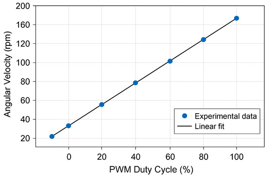
Figure 17.
Experimental response of the DC motors controlled with the MD03: relationship between PWM duty cycle and angular velocity.
In parallel, a voltage divider was designed and implemented to adapt the voltage levels of the solar panels to the ranges admitted by the Arduino Mega 2560. This circuit was developed as part of the experimental validation phase, confirming the applicability of the design previously modeled in Section 2.3. The implemented configuration (Figure 7) provided a proportional fraction of the input voltage according to Equation (16), allowing accurate measurement under real operating conditions.
Experimental verification demonstrated that the divider performed within the expected linear range, with deviations below 2% when compared to reference multimeter readings (Figure 16). This confirmed its suitability for integration into the embedded acquisition system.
Additionally, the dynamic characterization of the MD03 motor controllers and DC motors (Figure 17) was performed to evaluate the reliability of the control system during continuous operation. The results confirmed linear correspondence between PWM duty cycle and angular velocity, validating the expected response of the control architecture and ensuring stable power modulation under laboratory and field conditions.
It is important to note that, in the solar tracking system, the motors do not operate in continuous mode at different speeds but rather in very short intervals corresponding to specific adjustments of the panel’s position relative to the sun. In this context, the experimental characterization was used as a technical reference to validate the reliability of the MD03 controller and the motor under laboratory conditions, whereas in real operation the system prioritizes positioning accuracy and low energy consumption over sustained speed.
Furthermore, it was verified that the energy efficiency remained within a stable range, with an average consumption of 24 V during continuous operation and minimal thermal dissipation in the controllers. The stability of the motors under variable load conditions was evaluated during extended operating periods, with no significant losses of torque or interruptions in power supply.
The monocular vision system was integrated as a complementary control mechanism to improve the accuracy of solar tracker orientation. The camera employed was an endoscopic type, with a resolution of 640 × 480 pixels, a diameter of 7 mm, a 67° field of view, and resistance to adverse environmental conditions, with an operating range up to 176 °F. It was installed at the upper center of the photovoltaic array with a 90° angle relative to the solar trajectory, enabling direct capture of the sun’s relative position at each instant (Figure 8a).
The operating principle of the algorithm consisted of projecting solar rays, considered as three-dimensional points in space, onto the two-dimensional image plane of the camera. In this scheme, the origin of the camera coordinate system was defined at the optical aperture, and the projection of a 3D point () onto the 2D plane was represented as , as a function of the focal length (f) (Figure 8b). This model allowed visual information to be related to the panel’s orientation relative to the sun.
The monocular vision algorithm operates by continuously analyzing the images captured by the endoscopic camera to determine the centroid of the solar disk in real time. The image is converted from the RGB color space to HSV to isolate high-intensity regions corresponding to the sun, followed by adaptive thresholding and morphological filtering to eliminate noise and small reflections. The coordinates of the detected centroid (x, y) in the image plane are compared with the reference center of the frame, generating an error signal proportional to the displacement between both points. This error is then used as a feedback input for the control system, which adjusts the azimuth and elevation angles (θ1, θ2) through the MD03 motor controllers to reorient the panels. The algorithm operates at a sampling frequency of one frame per second, ensuring real-time response while maintaining computational efficiency on the embedded platform. This process enables continuous and autonomous correction of the panel’s orientation, ensuring that the subsequent image processing phase accurately reflects the system’s real-time behavior.
Image digitization and processing were performed on a computer using OpenCV (C++), enabling filtering and segmentation of regions of interest through color transformations in the HSV space, adaptive thresholding, and morphological operations. Table 3 presents the implemented algorithm, including the libraries used, the color parameters, and the routines for detection, filtering, and calculation of the centroid of the solar projection in the image plane.
Table 3.
Computer vision algorithm implemented in OpenCV (C++).
The integration of this information with the embedded control system enabled precise panel orientation, enhancing the robustness of the solar tracker against environmental variations and minimizing alignment errors.
3.3. Experiments
The initial tests were conducted with a fixed photovoltaic system composed of four Kyocera modules, model XD205GX-LP, installed at a tilt angle of 16° and oriented to the south, following technical recommendations from previous studies. In the region of Santo Domingo Tehuantepec, Oaxaca, the average annual solar radiation is approximately 5.8 kWh/m2·day, with temperatures ranging between 23 °C and 30 °C, and predominantly clear-sky conditions.
Figure 18 shows the power curve for a representative clear-sky day, recorded on 15 March 2024, which corresponds to the month with the highest solar irradiance in the region. On this day, the system reached a maximum power output of 722.8 W at 12:04 h, with an effective operating range between 9:30 h and 16:30 h. Furthermore, the interval between 11:00 h and 13:30 h corresponds to the peak solar hours, during which the highest energy capture was recorded.
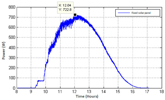
Figure 18.
Power curve of the photovoltaic system with fixed tilt on a representative operating day (15 April 2024).
In addition, Figure 19 illustrates another typical day under similar conditions, recorded on 25 April 2024, where the maximum power reached was 765.5 W at 12:21 p.m. In this case, the tracking system showed continuous capture from 9:30 a.m. until approximately 5:00 p.m.
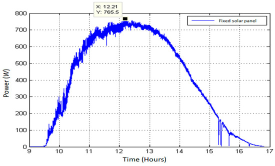
Figure 19.
Power curve of the photovoltaic system with fixed tilt on a representative operating day (25 March 2024).
Subsequently, the proposed dual-axis solar tracking system was evaluated with the implementation of the monocular vision algorithm. The results shown in Figure 20 correspond to the same experimental days as Figure 18 and Figure 19, i.e., 15 April and 25 March 2024, respectively. In both cases (Figure 20a,b), the tracking system successfully maintained the panel orientation perpendicular to the sun’s rays throughout the day, resulting in power outputs that reached values close to 800 W around solar noon.
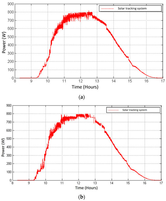
Figure 20.
Power curve of solar tracking system: (a) one characteristic day; (b) second characteristic day.
Figure 21 directly compares the power curve of the fixed system with the solar tracking system. A sustained increase in power is observed throughout the day for the tracking system, particularly during the early morning and post-noon hours, when the sun’s orientation shifts away from the optimal position of the fixed array.
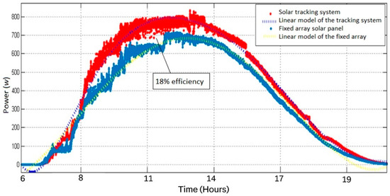
Figure 21.
Comparison of power curves between fixed system and solar tracking system.
According to the records, the proposed system achieved a relative increase in energy capture of approximately 18% compared to the fixed system. This result is consistent with values reported in the literature (13–15% for dual-axis systems), confirming the relevance of the kinematic model and the monocular vision algorithm implemented.
4. Discussion
The development and validation of the dual-axis solar tracking system presented in this study demonstrate significant improvements in energy capture efficiency and control precision, especially when compared to existing technologies. The innovative integration of a monocular vision algorithm with a kinematic model based on the Denavit–Hartenberg (D–H) convention provides high performance under real operating conditions.
Compared to the work of El Jaouhari et al. [44] which uses a digital hemispherical imager, our approach employs a compact endoscopic camera with effective visual tracking capabilities. While the hemispherical imaging method offers a wide field of view, it requires specialized optics and advanced image processing, increasing system complexity and cost. In contrast, the monocular vision strategy implemented in our system simplifies hardware requirements while maintaining accurate solar position detection throughout the day.
In the study by Abdollahpour et al., [45] a vision-based tracking system was developed using a standard webcam and image processing algorithms. Although their system achieved good alignment with the solar position, it was tested under limited conditions and lacked a formal kinematic modeling framework. Our system’s reliance on the D–H convention allows for a replicable and theoretically grounded control structure, enhancing system robustness and adaptability.
Issa et al. [29] proposed a fractional-order PID controller for a dual-axis tracker, focusing on control accuracy and system dynamics. While effective from a control theory perspective, such methods often require high computational resources and complex tuning processes. In contrast, our implementation prioritizes practical deployment by using standard PID controllers and optimizing tracking via monocular vision, striking a balance between performance and simplicity.
Wang et al. [46] introduced a dual-axis tracker driven by a single motor with optical sensors. Although this reduces mechanical complexity, it can limit tracking precision and adaptability. Our design uses two independent DC motors with PWM control and I2C communication, ensuring precise orientation in both azimuth and elevation, even under variable irradiance.
In contrast to photoelectric or time-based approaches, the embedded monocular vision system implemented in this study reduces component dependency, simplifies wiring, and sustains continuous tracking even under intermittent cloud cover. Meanwhile, the D–H-based kinematic modeling provides mathematical traceability to the control design, ensuring a reproducible and theoretically grounded implementation. This combination, validated in the field with four commercial photovoltaic modules, demonstrates a replicable pathway for improving solar energy capture in high-irradiance regions.
Finally, Jamroen et al., [47] developed a low-cost tracking system based on digital logic. Despite its economic feasibility, its tracking algorithm lacks real-time adaptability and environmental responsiveness. Our system enhances this aspect by leveraging visual data, allowing dynamic response to cloud movements and seasonal shifts in solar position.
The present work contributes to the field by integrating vision hardware, a well-established kinematic model, and real-time control under outdoor conditions. The proposed system outperforms previous designs in terms of scalability, accuracy, and practical implementation feasibility.
5. Conclusions
This work developed, implemented, and validated a dual-axis solar tracking system based on a kinematic model derived from the Denavit–Hartenberg convention, complemented by an embedded control system and a monocular vision algorithm. The integration of these three components demonstrated the technical and experimental feasibility of combining robotic modeling with intelligent control strategies to optimize solar radiation utilization under high-irradiance conditions.
Experimental results indicated that the proposed tracking system achieved an 18% relative improvement in energy efficiency compared to a fixed photovoltaic array. This increase was primarily observed during morning and afternoon hours, when fixed systems exhibit greater limitations in capturing solar radiation at optimal incidence angles. The calibration of the ACS712 current sensor and the voltage divider confirmed the accuracy of the data acquisition system, with relative errors below 3%, thereby validating the reliability of the recorded measurements.
The electronic instrumentation, based on the Arduino Mega 2560 and MD03 motor controllers, maintained stable performance under continuous operation, ensuring prototype reliability. Likewise, the endoscopic camera integrated into the monocular vision algorithm provided accurate solar position data, enhancing the system’s robustness against variable environmental conditions.
From a practical perspective, the proposed system demonstrates the technical feasibility of integrating kinematic modeling, embedded control, and monocular vision to optimize photovoltaic performance in high-irradiance environments. The experimental results confirm an 18% increase in energy capture compared to a fixed system, validating the effectiveness of the dual-axis tracking approach. However, it is important to note that this study did not include a cost analysis or economic evaluation. Therefore, any conclusions regarding affordability, scalability, or applicability in rural or low-resource areas should be considered beyond the present scope. Future work should address these aspects through a detailed techno-economic assessment to determine the financial viability of implementing such systems under different regional contexts.
Two main avenues for future research were identified: (i) optimizing the vision algorithm using artificial intelligence techniques to enhance detection accuracy under adverse weather conditions, and (ii) assessing the system on a larger scale and over extended periods to evaluate its long-term technical performance, maintenance requirements, and to conduct a detailed techno-economic feasibility analysis for potential replication in regions with similar solar conditions.
Author Contributions
Conceptualization, A.A.-B., V.A.-E., E.C.-M., M.P.-O. and R.C.-A.; methodology, A.A.-B., V.A.-E., E.C.-M. and H.F.A.-F.; software, A.A.-B., V.A.-E. and E.C.-M.; validation, A.A.-B., V.A.-E., E.C.-M., M.P.-O., J.A.E.-S. and H.F.A.-F.; formal analysis, A.A.-B., V.A.-E., E.C.-M., M.P.-O., R.C.-A., J.A.E.-S. and H.F.A.-F.; investigation, A.A.-B., V.A.-E., E.C.-M., M.P.-O., R.C.-A., J.A.E.-S. and H.F.A.-F.; resources, A.A.-B., V.A.-E., E.C.-M., M.P.-O., R.C.-A., J.A.E.-S. and H.F.A.-F.; data curation, A.A.-B., V.A.-E., E.C.-M., M.P.-O., R.C.-A., J.A.E.-S. and H.F.A.-F.; writing—original draft preparation, A.A.-B., V.A.-E., E.C.-M., M.P.-O., R.C.-A., J.A.E.-S. and H.F.A.-F.; writing—review and editing, A.A.-B., V.A.-E., E.C.-M., M.P.-O., R.C.-A., J.A.E.-S. and H.F.A.-F.; visualization, A.A.-B., V.A.-E., E.C.-M., M.P.-O., R.C.-A., J.A.E.-S. and H.F.A.-F.; supervision, A.A.-B., V.A.-E. and E.C.-M.; project administration, A.A.-B., V.A.-E. and E.C.-M.; funding acquisition, A.A.-B., V.A.-E., E.C.-M., M.P.-O., R.C.-A., J.A.E.-S. and H.F.A.-F. All authors have read and agreed to the published version of the manuscript.
Funding
This research received no external funding.
Data Availability Statement
The original contributions presented in this study are included in the article. Further inquiries can be directed to the corresponding author.
Conflicts of Interest
The authors declare no conflicts of interest.
References
- Saleh, H.M.; Hassan, A.I. The challenges of sustainable energy transition: A focus on renewable energy. Appl. Chem. Eng. 2024, 7, 2084. [Google Scholar] [CrossRef]
- Capellán-Pérez, I.; Álvarez-Antelo, D.; Miguel, L.J. Global Sustainability Crossroads: A Participatory Simulation Game to Educate in the Energy and Sustainability Challenges of the 21st Century. Sustainability 2019, 11, 3672. [Google Scholar] [CrossRef]
- Constante, D.M.A.; Erazo, C.R.R. The role of renewable energies in the transition to a sustainable energy model: Challenges and opportunities. J. Bus. Entrep. Stud. 2024, 8, 38–48. [Google Scholar] [CrossRef]
- Johnsson, F.; Kjärstad, J.; Rootzén, J. The threat to climate change mitigation posed by the abundance of fossil fuels. Clim. Policy 2019, 19, 258–274. [Google Scholar] [CrossRef]
- Abbasi, K.R.; Shahbaz, M.; Zhang, J.; Irfan, M.; Alvarado, R. Analyze the environmental sustainability factors of China: The role of fossil fuel energy and renewable energy. Renew. Energy 2022, 187, 390–402. [Google Scholar] [CrossRef]
- Borowski, P.F. Mitigating climate change and the development of green energy versus a return to fossil fuels due to the energy crisis in 2022. Energies 2022, 15, 9289. [Google Scholar] [CrossRef]
- Izam, N.S.M.N.; Itam, Z.; Sing, W.L.; Syamsir, A. Sustainable development perspectives of solar energy technologies with focus on solar Photovoltaic—A review. Energies 2022, 15, 2790. [Google Scholar] [CrossRef]
- Ebhota, W.S.; Jen, T.C. Fossil Fuels Environmental Challenges and the Role of Solar Photovoltaic Technology Advances in Fast Tracking Hybrid Renewable Energy System. Int. J. Precis. Eng. Manuf.-Green Technol. 2020, 7, 97–117. [Google Scholar] [CrossRef]
- Victoria, M.; Haegel, N.; Peters, I.M.; Sinton, R.; Jäger-Waldau, A.; Del Cañizo, C.; Smets, A. Solar photovoltaics is ready to power a sustainable future. Joule 2021, 5, 1041–1056. [Google Scholar] [CrossRef]
- Bošnjaković, M.; Santa, R.; Crnac, Z.; Bošnjaković, T. Environmental Impact of PV Power Systems. Sustainability 2023, 15, 11888. [Google Scholar] [CrossRef]
- Cui, C.; Lonergan, K.E.; Sansavini, G. Policy-driven transformation of global solar PV supply chains and resulting impacts. Nat. Commun. 2025, 16, 6742. [Google Scholar] [CrossRef]
- IEA. Share of Renewable Electricity Generation by Technology, 2000–2030. IEA, Paris, 2024. Available online: https://www.iea.org/energy-system/renewables (accessed on 19 October 2025).
- Lee, H.; Calvin, K.; Dasgupta, D.; Krinner, G.; Mukherji, A.; Thorne, P.; Zommers, Z. Climate Change 2023: Synthesis Report. Contribution of Working Groups I, II and III to the Sixth Assessment Report of the Intergovernmental Panel on Climate Change; IPCC: Geneva, Switzerland, 2023. [CrossRef]
- Ritchie, H.; Roser, M.; Rosado, P. Renewable Energy, Published Online at OurWorldinData.org. 2020. Available online: https://ourworldindata.org/renewable-energy (accessed on 1 August 2025).
- Lewis, N.S. Research opportunities to advance solar energy utilization. Science 2016, 351, 6271. [Google Scholar] [CrossRef]
- Acosta-Banda, A.; Aguilar-Esteva, V.; Hechavarría Difur, L.; Campos-Mercado, E.; Cortés-Martínez, B.; Patiño-Ortiz, M. Grid-Connected Photovoltaic Systems as an Alternative for Sustainable Urbanization in Southeastern Mexico. Urban Sci. 2025, 9, 329. [Google Scholar] [CrossRef]
- Soomar, A.M.; Hakeem, A.; Messaoudi, M.; Musznicki, P.; Iqbal, A.; Czapp, S. Solar photovoltaic energy optimization and challenges. Front. Energy Res. 2022, 10, 879985. [Google Scholar] [CrossRef]
- Bin Abu Sofian, A.D.A.; Lim, H.R.; Siti Halimatul Munawaroh, H.; Ma, Z.; Chew, K.W.; Show, P.L. Machine learning and the renewable energy revolution: Exploring solar and wind energy solutions for a sustainable future including innovations in energy storage. Sustain. Dev. 2024, 32, 3953–3978. Available online: https://onlinelibrary.wiley.com/doi/full/10.1002/sd.2885 (accessed on 6 November 2025). [CrossRef]
- Stojanovski, O.; Thurber, M.; Wolak, F. Rural energy access through solar home systems: Use patterns and opportunities for improvement. Energy Sustain. Dev. 2017, 37, 33–50. [Google Scholar] [CrossRef]
- Akikur, R.K.; Saidur, R.; Ping, H.W.; Ullah, K.R. Comparative study of stand-alone and hybrid solar energy systems suitable for off-grid rural electrification: A review. Renew. Sustain. Energy Rev. 2023, 27, 738–752. [Google Scholar] [CrossRef]
- Koussa, M.; Cheknane, A.; Hadji, S.M.H.S.N.; Haddadi, M.; Noureddine, S. Measured and modelled improvement in solar energy yield from flat plate photovoltaic systems utilizing different tracking systems and under a range of environmental conditions. Appl. Energy 2011, 88, 1756–1771. [Google Scholar] [CrossRef]
- Sumathi, V.; Jayapragash, R.; Bakshi, A.; Akella, P.K. Solar tracking methods to maximize PV system output–A review of the methods adopted in recent decade. Renew. Sustain. Energy Rev. 2017, 74, 130–138. [Google Scholar] [CrossRef]
- Vieira, R.G.; Guerra, F.K.; Vale, M.R.; Araújo, M.M. Comparative performance analysis between static solar panels and single-axis tracking system on a hot climate region near to the equator. Renew. Sustain. Energy Rev. 2016, 64, 672–681. [Google Scholar] [CrossRef]
- Musa, A.; Alozie, E.; Suleiman, S.A.; Ojo, J.A.; Imoize, A.L. A Review of Time-Based Solar Photovoltaic Tracking Systems. Information 2023, 14, 211. [Google Scholar] [CrossRef]
- Hafez, A.Z.; Yousef, A.M.; Harag, N.M. Solar tracking systems: Technologies and trackers drive types—A review. Renew. Sustain. Energy Rev. 2018, 91, 754–778. [Google Scholar] [CrossRef]
- Hang, H.; Shen, W. Design and implementation of a dual-axis solar tracking system. Energies 2023, 16, 6330. [Google Scholar] [CrossRef]
- Nextracker. Optimizing Your Energy Yield with TrueCapture. Nextracker Inc., 2023. Available online: https://info.nextracker.com/optimizing-your-energy-yield-white-paper/ (accessed on 6 November 2025).
- Sadeghi, R.; Parenti, M.; Memme, S.; Fossa, M.; Morchio, S. A Review and Comparative Analysis of Solar Tracking Systems. Energies 2025, 18, 2553. [Google Scholar] [CrossRef]
- Issa, H.A.; Abdali, L.M.; Alhusseini, H.; Velkin, V.I. Design, Modeling, and Control of a Dual-Axis Solar Tracker Using Fractional Order PID Controllers for Enhanced Energy Efficiency. Results Eng. 2025, 27, 106073. [Google Scholar] [CrossRef]
- Demirdelen, T.; Alıcı, H.; Esenboğa, B.; Güldürek, M. Performance and Economic Analysis of Designed Different Solar Tracking Systems for Mediterranean Climate. Energies 2023, 16, 4197. [Google Scholar] [CrossRef]
- Mauro, S.; Battezzato, A.; Biondi, G.; Scarzella, C. Design and test of a parallel kinematic solar tracker. Adv. Mech. Eng. 2015, 7, 1687814015618627. [Google Scholar] [CrossRef]
- Engin, M.; Engin, D. Optimization controller for mechatronic sun tracking system to improve performance. Adv. Mech. Eng. 2013, 5, 146352. [Google Scholar] [CrossRef]
- López, J.A.P.; Soto, A.L.; Ramos, F.B.; Flores, B.G. Comparativa de la eficiencia entre un sistema fotovoltaico con seguimiento solar y un sistema fotovoltaico fijo/Comparison between a photovoltaic solar tracker efficiency and a fixed photovoltaic system. CIBA Rev. Iberoam. Las Cienc. Biológicas Agropecu. 2018, 7, 105–129. [Google Scholar] [CrossRef]
- Arreola Gómez, R.; Quevedo Nolasco, A.; Castro Popoca, M.; Bravo Vinaja, Á.; Reyes Muñoz, D. Design, construction and evaluation of a solar tracking system for a photovoltaic panel. Rev. Mex. Cienc. Agrícolas 2015, 6, 1715–1727. [Google Scholar]
- Denavit, J.; Hartenberg, R.S. A Kinematic Notation for Lower-pair Mechanisms Based on Matrices. J. Appl. Mech. 1995, 22, 215–221. [Google Scholar] [CrossRef]
- Spong, M.W.; Vidyasagar, M. Robot Dynamics and Control. Wiley: Austin, TX, USA, 1991. [Google Scholar]
- Kelly, R.; Santibáñez, V. Control de Movimiento de Robots Manipuladores; Pearson Educación, Prentice Hall: London, UK, 2003; ISBN 84-205-3831-0. [Google Scholar]
- Allegro MicroSystems. ACS712: Fully Integrated, Hall-Effect-Based Linear Current Sensor IC with 2.1 kVRMS Isolation and a Low-Resistance Current Conductor. 2022. Available online: https://www.allegromicro.com/-/media/Files/Datasheets/ACS712-Datasheet.ashx (accessed on 6 November 2025).
- International Renowable Energy Agency. Análisis del Mercado de Energías Renovables: América Latina; IRENA: Abu Dhabi, United Arab Emirates, 2016; ISBN 978-92-95111-50-9. [Google Scholar]
- International Renowable Energy Agency. Energía Solar en México: Su Potencial y Aprovechamiento; Centro de Investigación Económica y Presupuestaria: Mexico City, Mexico, 2015. [Google Scholar]
- Nasa Power, Data Access Viewer (DAV). Parámetros en Santo Domingo Tehuantepec 2025. Available online: https://power.larc.nasa.gov/data-access-viewer/ (accessed on 19 October 2025).
- Darhmaoui, H.; Lahjouji, D. Latitude based model for tilt angle optimization for solar collectors in the Mediterranean region. Energy Procedia 2013, 42, 426–435. [Google Scholar] [CrossRef]
- Handoyo, E.A.; Ichsani, D. The optimal tilt angle of a solar collector. Energy Procedia 2013, 32, 166–175. [Google Scholar] [CrossRef]
- El Jaouhari, Z.; Zaz, Y.; Moughyt, S.; El Kadmiri, O.; El Kadmiri, Z. Dual-axis solar tracker design based on a digital hemispherical imager. J. Sol. Energy Eng. 2019, 141, 011001. [Google Scholar] [CrossRef]
- Abdollahpour, M.; Golzarian, M.R.; Rohani, A.; Zarchi, H.A. Development of a machine vision dual-axis solar tracking system. Sol. Energy 2018, 169, 136–143. [Google Scholar] [CrossRef]
- Wang, J.-M.; Lu, C.-L. Design and Implementation of a Sun Tracker with a Dual-Axis Single Motor for an Optical Sensor-Based Photovoltaic System. Sensors 2013, 13, 3157–3168. [Google Scholar] [CrossRef]
- Jamroen, C.; Komkum, P.; Kohsri, S.; Himananto, W.; Panupintu, S.; Unkat, S. A low-cost dual-axis solar tracking system based on digital logic design: Design and implementation. Sustain. Energy Technol. Assess. 2020, 37, 100618. [Google Scholar] [CrossRef]
Disclaimer/Publisher’s Note: The statements, opinions and data contained in all publications are solely those of the individual author(s) and contributor(s) and not of MDPI and/or the editor(s). MDPI and/or the editor(s) disclaim responsibility for any injury to people or property resulting from any ideas, methods, instructions or products referred to in the content. |
© 2025 by the authors. Licensee MDPI, Basel, Switzerland. This article is an open access article distributed under the terms and conditions of the Creative Commons Attribution (CC BY) license (https://creativecommons.org/licenses/by/4.0/).