Article

The Role of Double-Φ Floating Semi-Submersible Vertical Axis Wind Turbines in Suppressing the Gyroscopic Effect

1
School of Mechanical and Electrical Engineering, Jinling Institute of Technology, No. 99 Hongjing Avenue, Nanjing 210001, China
2
Zhejiang Yongsheng Technology Co., No. 1 Chunhui Road, Fuyang District, Hangzhou 311400, China
*
Authors to whom correspondence should be addressed.
Energies 2025, 18(21), 5847; https://doi.org/10.3390/en18215847
Submission received: 27 September 2025 / Revised: 28 October 2025 / Accepted: 4 November 2025 / Published: 6 November 2025
(This article belongs to the Special Issue Advances in Offshore Renewable Energy Systems)

Abstract

The gyroscopic effect has significant impacts on the stability, dynamic behavior, and vibration characteristics of high-speed rotating systems. A floating offshore vertical axis wind turbine (FOVWT) exhibits gyroscope-like motions under combined wind–wave–current conditions; the attitude angles of the shaft connected to the platform change continuously in space, making the overall system’s gyroscopic effect more pronounced. From a geometric perspective, this study investigates a method to suppress the gyroscopic effect of floating offshore vertical axis wind turbines: replacing the conventional single-Φ rotor with a stagger-mounted double-layer double-Φ rotor. This configuration exploits the phase difference in circumferential (i.e., 360° around the rotor) aerodynamic loads experienced by the upper and lower rotors; the superposition of these loads ultimately reduces the platform’s pitch response. This study adopts computational fluid dynamics (CFD) for numerical simulations. First, using the NREL 5-MW OC4 floating horizontal axis wind turbine (FOHWT) platform as the research object, we computed the platform’s motion responses under different environmental conditions and verified the effectiveness of the numerical method through comparison with published literature data. Then, under the same marine environment, we compared the motion responses of the conventional single-Φ turbine and double-Φ turbines with different misalignment angles. The results show that modifying the Φ-type rotor configuration can effectively reduce the axial load on the rotor and enhance system stability. As the rotor misalignment angle increases from 15° to 90°, the pitch motion amplitude decreases from 20.6% to 11.8%, while the overall turbine power is only slightly reduced.

1. Introduction

Amid the sustained growth in the global energy demand and mounting ecological pressures, the traditional fossil fuel-based energy system is increasingly unable to support sustainable socioeconomic development [1]. To achieve energy security and ecological sustainability, the development and utilization of renewable energy has become an inevitable pathway to addressing the global energy crisis. As a key form within the renewable energy portfolio, wind power has grown markedly in recent years, with continuous advances in technology and installed capacity [2]. According to projections [3], by 2030 the share of variable renewable energy in global renewable electricity generation will increase by two-thirds from today’s level of under 45%; the share of solar PVs in the global electricity demand will triple and wind power will nearly double, while the role of hydropower will relatively decline.
Onshore wind is a proven and mature technology with a well-established global supply chain. Over the past five years, continued advancements have enabled a higher energy yield per unit capacity and facilitated resource development in low-wind regions [4]. Turbine designs are trending toward larger scales—with increasing tower heights and rotor diameters—thereby significantly improving energy conversion efficiency [5]. However, suitable onshore wind resources are becoming scarce, the construction of large onshore wind farms faces constraints in many regions, and potential adverse impacts on local environments and communities persist. In contrast, offshore wind has enormous potential [6]. Deploying turbines at sea leverages higher wind speeds and lower turbulence while distancing projects from densely populated areas, thus reducing environmental and social externalities. Consequently, offshore wind is emerging worldwide—especially in countries endowed with abundant near-shore wind resources—as a major direction and new growth pole for the wind sector. Floating offshore wind turbines (FOWTs) are commonly classified by floater type and mooring system. Among projects that are in operation, under construction, or approved, four main platform types prevail, as shown in Figure 1: (a) spars, (b) semi-submersible, (c) tension leg platforms (TLPs), and (d) barges [7].
A slender cylindrical pontoon forms the spar-type floater. Owing to the large bottom ballast that lowers the center of gravity, the spar has a deep draft and excellent wind–wave resistance; it is typically deployed in deep water [8]. A semi-submersible platform consists of multiple pontoons, columns, and connecting beams, achieving stability through buoyancy and ballasts. It is held in place by a multi-point mooring system, offering a strong anti-capsize capability and requiring relatively modest seabed conditions; however, it exhibits larger motion responses and entails larger hull dimensions and material usage [9]. A TLP consists of a floater and several tensioned legs (tendons) anchored to the seabed, which provide restoring constraints and minimize heave motion; nevertheless, it demands higher-quality seabed conditions and is suitable for deeper waters [10]. A barge-type floater has a shallow draft but a large waterplane area; while the large waterplane confers sufficient initial stability, excessive pitch may occur under wave action [11].
At present, almost all floating wind turbines that have undergone sea trials, demonstrations, or commercial deployment are horizontal axis machines, indicating that floating offshore horizontal axis wind turbines (FOHWTs) dominate offshore wind energy conversion [12]. Researchers have conducted extensive studies on maximizing energy production [13,14,15], wind farm layout optimization [16,17,18,19], and control optimization [20,21,22]. However, floating offshore wind turbines still face major challenges, including complex installation, stability issues induced by deep water dynamics, and increased maintenance demands. Floating offshore vertical axis wind turbines (FOVWTs) represent one possible solution: they feature a mechanically simpler architecture than FOHWTs and do not require a yaw system because they are insensitive to the wind direction. In addition, the drivetrain and generator are arranged closer to the free surface, effectively lowering the structural center of gravity and stresses; as a result, FOVWTs offer advantages in power density, directional insensitivity, and operation and maintenance [23,24,25,26].
Unlike bottom-fixed turbines, a floating offshore wind turbine (FOWT) undergoes six-degree-of-freedom (6-DOF) platform motions under combined wind–wave excitation, which can degrade the aerodynamic performance and introduce additional structural loads. During the rotor spin, the blades are simultaneously subjected to aerodynamic forces, centrifugal force, gravity, and gyroscopic effects. The gyroscopic effect refers to a spinning body’s resistance to changes in the direction of its spin axis due to its angular momentum L: when the platform experiences a small angular velocity vector Ω (roll/pitch/yaw), a gyroscopic moment Mg = L × Ω arises, inducing the precession of the rotor axis [27]. This phenomenon has been extensively studied in high-speed rotating machinery, such as flywheels, helicopter rotors, and steam turbines, and it critically affects the stability, vibration, and dynamic response [28]. For FOWTs, the coupling between the rotor angular momentum and platform attitude–rate produces notable cross-coupling between the pitch and yaw; macroscopically, the rotor axis precesses with an angular rate, sweeping a horizontal circular trajectory (Figure 2), thereby altering the global dynamics and elevating load levels.
Prior studies have shown [29,30,31] that, relative to horizontal axis wind turbines (HAWTs), vertical axis wind turbines (VAWTs) exhibit milder platform–rotor coupling on floating platforms. Because the VAWT spin axis coincides with the platform’s yaw axis, yaw motion generates nearly zero gyroscopic torque for an ideally symmetric VAWT. In addition, VAWTs are largely insensitive to wind direction, yielding weaker responses to wind direction changes than HAWTs. Consequently, VAWTs may display enhanced stability on floating platforms.
However, a persistent tilt (here the “tilt angle” denotes the deviation of the turbine axis from the vertical) introduces several issues. Excessive tilt reduces the swept area and hence power output; sustained inclination also increases base loads at the tower foot, raises material demands, and may trigger fatigue damage, posing safety risks. Given these adverse impacts, suppressing the pitch motion has become a key focus in offshore wind research. One effective pathway is to seek and optimize appropriate mitigation strategies. According to Borg et al. [25], catenary moorings primarily limit the “horizontal” degrees of freedom—including the pitch rotation and heave/sway translations—whereas taut-leg (tensioned) moorings can restrain all 6-DOF motions. Platform motions affect rotor aerodynamics, and the varying aerodynamics, in turn, feed back on platform motion. Liu et al. [32] examined the use of clump weights attached at various positions along mooring lines to improve the wave resistance capability of the OC3-Hywind FOWT, finding a strong sensitivity of platform responses to the weight location and only a limited heave reduction with an increased mass. Zhang et al. [33] proposed tuned mass dampers (TMDs) to suppress floating turbine vibrations, demonstrating an effective attenuation of platform–tower coupled responses. Zheng et al. [34] investigated clump weight mass effects on floating platform motions, showing that larger masses reduce the maximum mooring tension and oscillation amplitudes, as well as the maxima and means of the surge and pitch. Saghi et al. [11] installed bi-directional tuned liquid dampers on a barge-type FOWT and achieved a 10–30% reduction in pitch. Wang et al. [35] used a gyroscopic stabilizer to suppress the platform pitch—providing good suppression under positive damping. Cayuela-Padilla et al. [36] proposed a six-floater platform hybridized with oscillating water columns (OWCs) to suppress the pitch/yaw, with certain configurations markedly reducing rotational responses. Zhao et al. [37] optimized heave plates for a semi-submersible, showing controller-free reductions in the low-frequency pitch and heave. Effective control strategies are likewise crucial to address these coupled effects in FOWT design: among single-turbine-oriented controls, pitch control is particularly promising for achieving near-optimal power while reducing mechanical loads [38,39]. Shangmao [40] reported integrated individual pitch control (I-IPC) and integrated collective pitch control (I-CPC), which improved heave, surge, and pitch responses and increased the generator power. Wang et al. [41] developed a mechanical cyclic pitch control (CPC) targeting aerodynamic torque minimization, significantly reducing large fatigue-inducing aerodynamic loads arising from the platform pitch without sacrificing energy production.
Despite these advances, most prior work suppresses platform motions via “external system” optimization (platform design, moorings, and controllers), while relatively few studies target turbine–structural design to weaken gyroscopic effects at the source. To this end, the present study proposes geometry-based mitigation for floating offshore vertical axis wind turbines (FOVWTs): replacing the conventional single-Φ rotor with a staggered double-Φ two-tier rotor to suppress pitch responses. First, a CFD framework is validated against benchmark data for a horizontal axis FOWT. Next, the motion responses of single-Φ and double-Φ rotors are compared under different wind–wave conditions. Finally, the suppression effect of the rotor misalignment angle φ on the pitch motion is assessed systematically.

2. Methodology

2.1. Model Setup

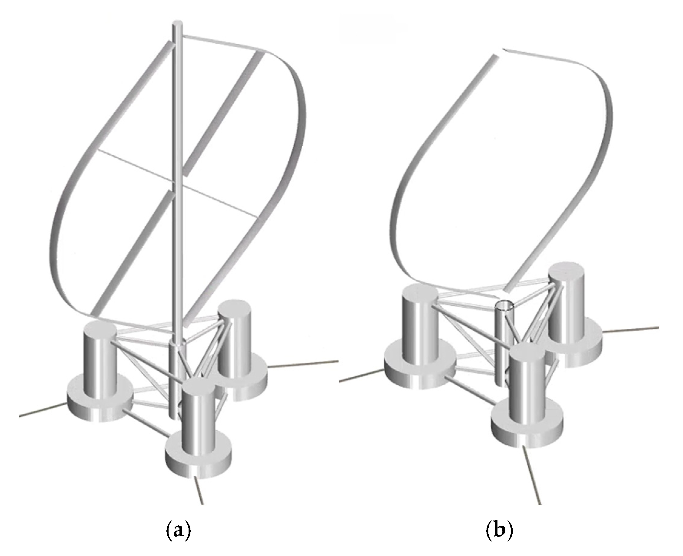
As shown in Figure 3a, the semi-submersible floating offshore vertical axis wind turbine (FOVWT) system consists of a VAWT rotor, a tower connected to the generator, blade connectors, a semi-submersible platform, and a mooring system. The entire system undergoes six-degree-of-freedom (6-DOF) motions under coupled wind–wave–current conditions, while the turbine rotor rotates about its shaft. The mooring system constrains the motion of the overall wind turbine system. For computational simplification, as shown in Figure 3b, the tower and supporting members are omitted in the model setup.
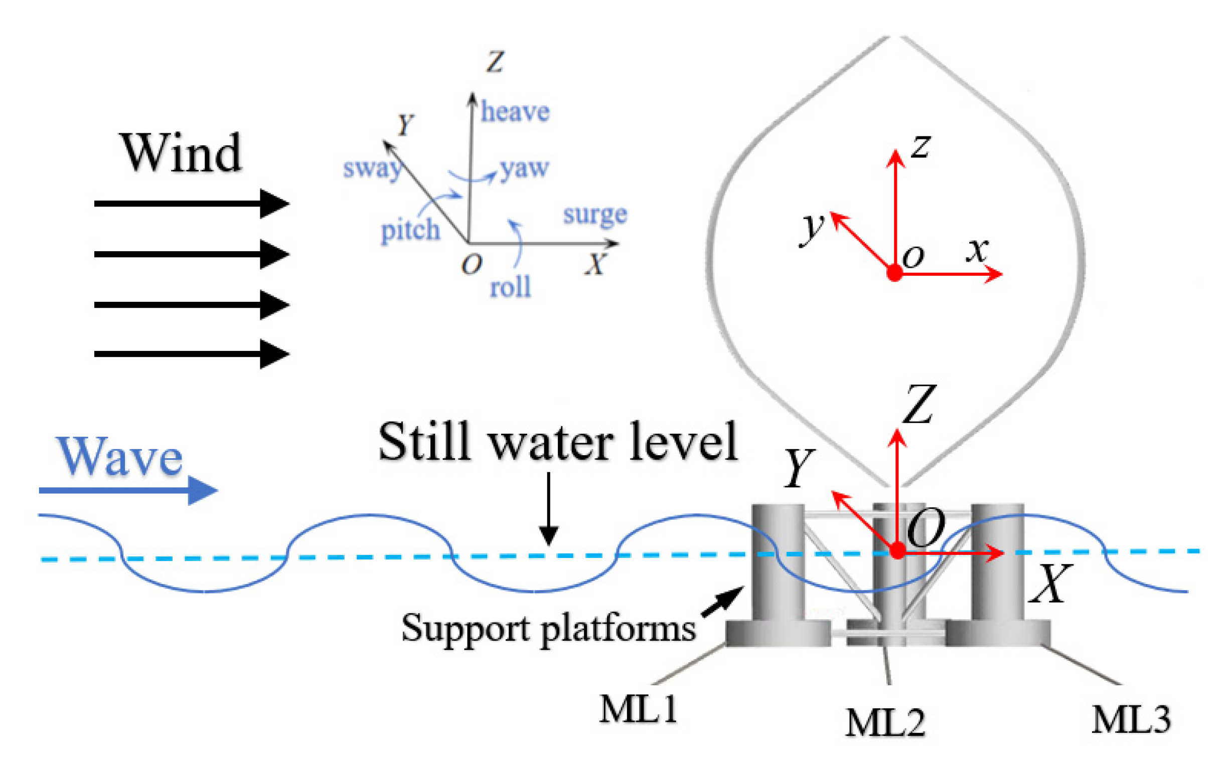
As shown in Figure 4, to investigate how the gyroscopic effect influences the platform motion response and turbine loading of a floating wind turbine, two coordinate systems are first established to, respectively, describe the platform response under wind–wave–current excitation and the aerodynamic loads on the turbine rotor.
The first is the global coordinate system (O: XYZ), whose origin O is located at the overall center of the mass of the floating wind turbine system. The X-O-Y plane lies on the still water level; the positive X-axis is aligned with the wave propagation direction; and the Z-axis is normal to the free surface, pointing toward the tower top. This frame is used to describe the wind–wave–current motions in the numerical wave tank and the overall platform response.
The second is a body-fixed Cartesian coordinate system (o: xyz) attached to the turbine rotor. When the system is at rest, its origin o is placed at the geometric center of the VAWT rotor; the positive x-axis is aligned with the wave propagation direction, and the z-axis follows the tower’s vertical direction. This frame is used to describe the mean and instantaneous aerodynamic loads on the turbine. The incoming flow direction of the VAWT is consistent with the positive global X-axis.

2.2. Parameter Definitions

To ensure the consistency and comparability of the numerical simulations, the key dimensionless parameters adopted in this study are summarized in Table 1. These parameters provide a basis for analyzing the hydrodynamic and aerodynamic performance of the FOWT system.
Tip Speed Ratio ( λ ): λ is an important dimensionless parameter that measures the relationship between the blade rotational speed and the wind speed. Its definition is as follows:
λ   =   ω R V
Power Coefficient ( C P ): The ratio of extracted power to the available wind power passing through the rotor swept area:
C P = Q ω 0.5 ρ V A 3 S
C F x and C F y are dimensionless representations of the normal force ( C F x ) and tangential force ( C F y ) acting on an individual blade. Their definitions are as follows:
C F x   =   F x 0.5 ρ V 2   S
C F y = F y 0.5 ρ V 2   S

2.3. CFD Numerical Method

2.3.1. Governing Equations and Turbulence Model

The incompressible Reynolds-averaged Navier–Stokes (RANS) equations can be written in Cartesian index form with Einstein’s summation convention as follows (an overbar denotes Reynolds averaging, and a prime denotes fluctuations).
μ i x i = 0
ρ u i ¯ t + ρ u j ¯ u i ¯ x j = f i ¯ p i ¯ x i + x j ( μ u i ¯ x j ρ μ i μ j ¯ )
where μ i   μ j is the mean velocity component, μ i μ j is the fluctuating velocity, μ is the dynamic viscosity, p is the pressure, and ρ μ i μ j ¯ denotes the Reynolds stress term. To render the governing equations closed, a turbulence model is required. Since the S S T k ω model can capture the dynamic stall characteristics of rotating blades with good fidelity, it is adopted in the present computations [42,43,44].

2.3.2. Implementation of FOVWT Motions

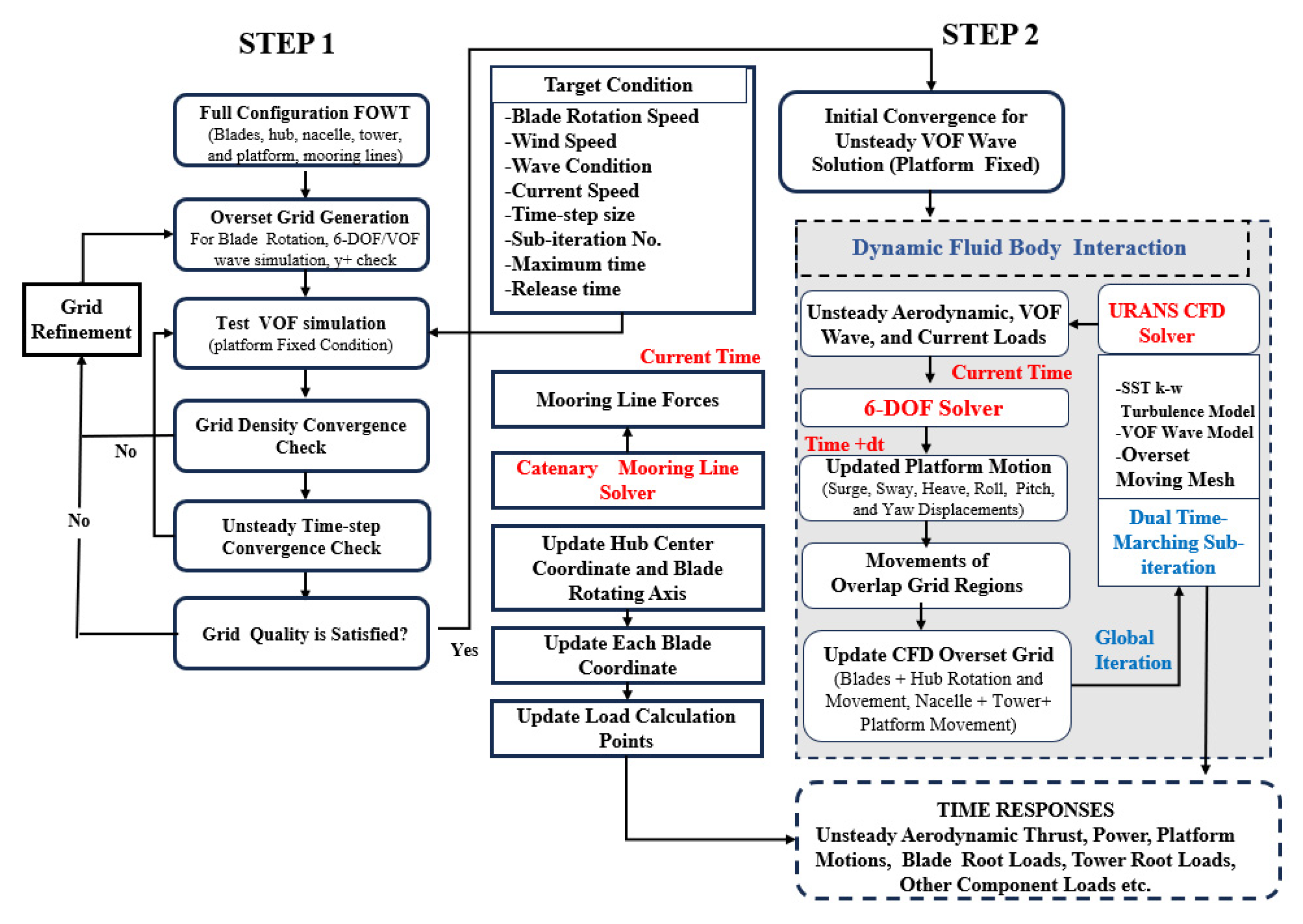
As shown in Figure 5, the CFD workflow resolves both the aerodynamic loads on the FOVWT and the platform’s motion response. The Dynamic Fluid Body Interaction (DFBI) is a numerical technique for describing the interaction between a fluid and a rigid body; within the CFD framework, it simultaneously solves the fluid governing equations and the rigid-body equations of motion, thereby achieving two-way coupling between the flow field and structural motion. In this model, the fluid is described by the Navier–Stokes equations, and the velocity and pressure fields are obtained via the finite volume method or other discretization schemes. The rigid body motion is updated using the given moments of inertia and mass according to Newton’s second law and the Euler equations. The pressure and viscous shear on the platform surface are integrated to yield the total hydrodynamic load, which—together with the mooring restoring forces and wind-induced loads—drives the platform’s six-degree-of-freedom (6-DOF) motion. Meanwhile, the platform’s instantaneous position and attitude modify the boundary conditions of the computational domain, thereby realizing dynamic feedback coupling between the fluid and the body.

2.4. Validation of Effectiveness

In numerical simulations of FOWTs, the coupling between the hydrodynamics acting on the platform and the unsteady aerodynamics on the turbine rotor is the key factor determining the accuracy of motion–response predictions, particularly under extreme wind–wave conditions. To ensure the reliability of the analysis, it is essential to accurately capture the interaction between the rotor blade aerodynamics and platform hydrodynamics and to employ a thoroughly validated numerical model. Because studies on FOVWTs are relatively scarce, the present work conducts a verification based on the fully coupled numerical model of the NREL 5-MW OC4 floating wind turbine developed by Goupee A. J. [46]. The validation mainly includes comparisons of free-decay responses and platform dynamic characteristics, in order to assess the consistency of the model results with existing experimental data and CFD studies, thereby confirming the model’s accuracy and applicability.

2.4.1. Mesh Generation

To accommodate large-scale computations, a hexahedron-dominant trimmed mesh is used to discretize the entire domain. This mesh achieves a higher local cell density in key regions while maintaining a relatively low total cell count in non-critical regions, thereby balancing numerical stability and computational efficiency.
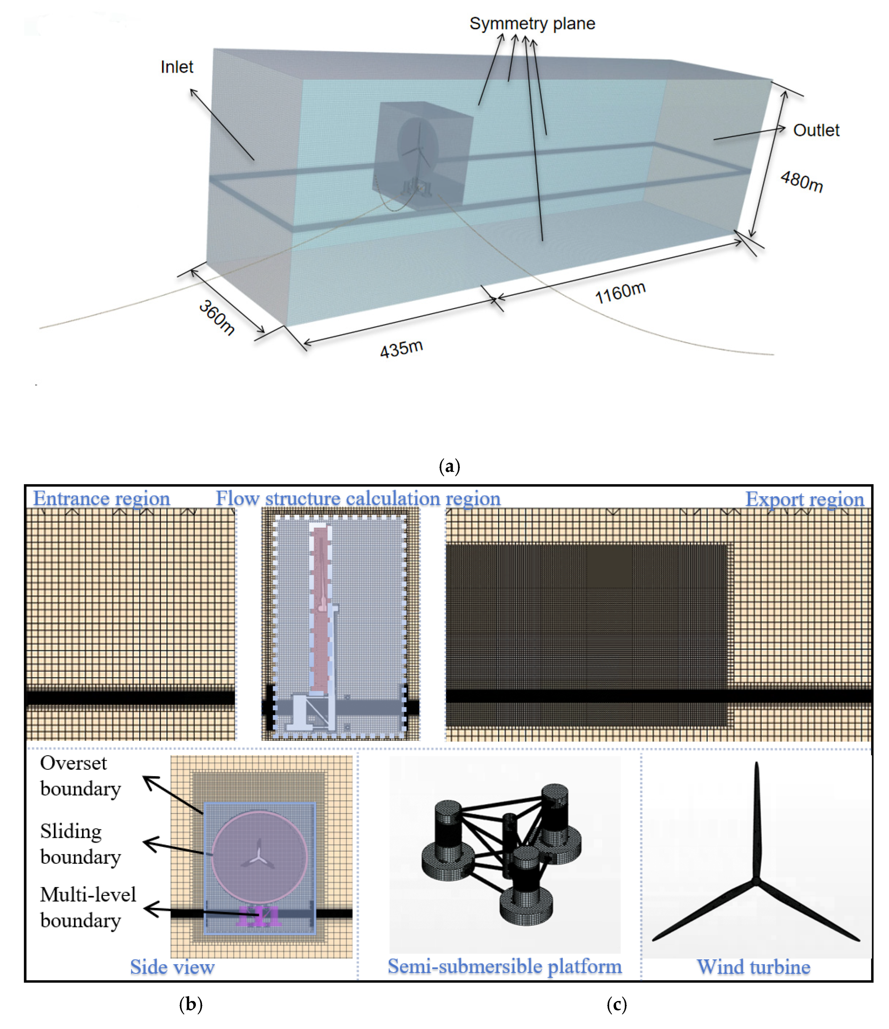
The mesh configuration shown in Figure 6a presents the overall layout, Figure 6b presents the side view, and Figure 6c shows the front view, clearly showing the regional discretization and the use of dynamic mesh techniques. In the two-dimensional cross-section, the computational domain is divided into three parts: the fluid region, the six-degree-of-freedom (6-DOF) region, and the rotating region. The flow is two-phase air–water; the mesh refinement is applied near the free surface and in the rotor wake region. The wave refinement criteria are kept consistent: at least 20 cells per wave height in the vertical direction and at least 80 cells per wavelength along the propagation direction [47]. To accurately capture the wake structure, a volumetric control zone is defined with a smooth transition to the background mesh. Platform 6-DOF motions are realized via an overset mesh, while the blade rotation is implemented using a sliding mesh with superimposed motion.
To resolve near-wall flows, a hybrid strategy combining trimmed hexahedra and prism layers is adopted: total boundary layer thickness is 0.03 m, growth rate is 1.2, 8 layers, and first layer thickness is 0.0018 m. The total cell count is approximately 12 million. To ensure interpolation quality and convergence, the cell size in the rotating region is chosen to be nearly the same as in the background field.

2.4.2. Boundary Conditions

As shown in Figure 6a, the rectangular computational domain measures 1595 m × 360 m × 480 m, with a water depth of 200 m. The free surface is captured using the volume-of-fluid (VOF) method. A velocity inlet is prescribed at the inflow boundary, and a pressure outlet is specified at the outflow boundary. The distances from the platform center to the inlet and outlet are 435 m and 1160 m, respectively.
Two symmetry planes are applied in the Y-direction at a location 180 m from the platform, in order to reduce the domain size and computational cost. The mooring anchors are placed outside the flow domain, and—after the buoyancy correction—the platform is modeled using an equivalent density of 108.38 kg·m−3. The environmental conditions correspond to a rated wind speed of 11.4 m/s, a significant wave height of 7.58 m, and a wave period of 12.1 s.
To suppress startup transients and allow the flow to stabilize before releasing platform motion, a release time of 0.5 s and a relaxation time of 5 s are used. Fifth-order Stokes waves are adopted for wave generation to ensure high-fidelity wave characteristics. In a finite computational domain, if the outflow boundary is not configured with a non-reflective treatment, partial reflection will occur when the wave reaches the boundary. The superposition of incident and reflected waves can generate standing waves and secondary harmonics, which contaminate the free surface time history and load response evaluations. To avoid wave reflections at the outlet, a damping method is employed [48,49,50].

2.4.3. Result Validation

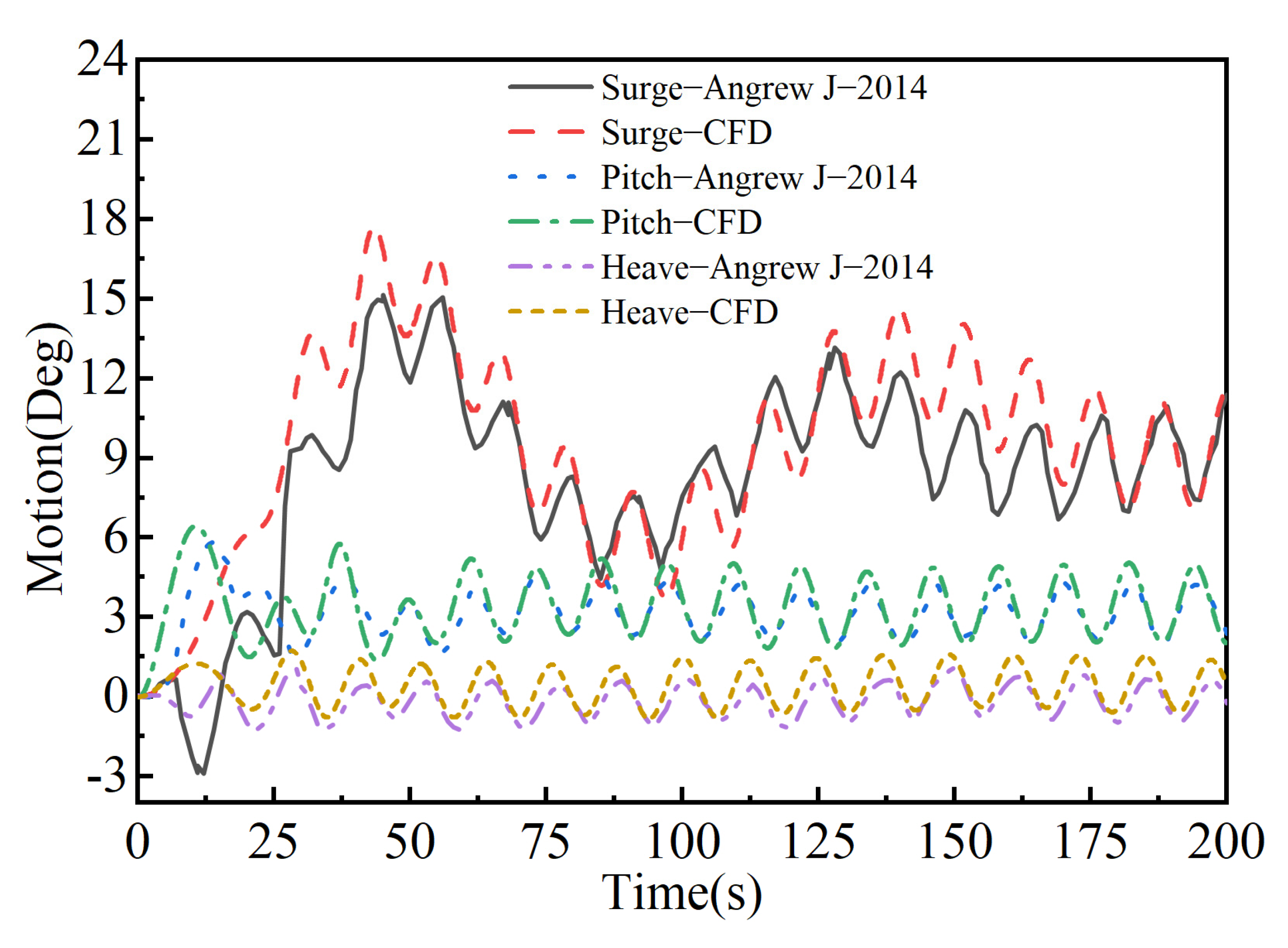
To ensure the reliability of the analysis, it is necessary to accurately capture the interaction between the aerodynamic forces on the rotor blades and the hydrodynamic forces on the supporting platform. Therefore, the fully coupled numerical model established in this study (NREL 5-MW OC4 FOWT) is compared against the validated numerical model reported by Goupee A. J. [46]. As shown in Figure 7, the numerical results agree with the experimental data. A comparison of the natural periods is summarized in Table 2, with a maximum error below 6%, indicating that the selected turbulence model provides sufficient accuracy for the subsequent simulations.
According to international standards such as DNVGL-ST-0119 and IEC 61400-3, the pitch angle of a floating wind turbine during steady operation should remain within ±8° to ensure platform stability and structural load safety. In the absence of dedicated design standards for FOVWTs, the present study refers to FOHWT international standards and design experience during the design and validation process. This practice is common and reasonable because FOHWTs and FOVWTs share similar requirements in terms of hydrodynamic stability, mooring safety, and ultimate load constraints. Our numerical results show that the maximum platform pitch is approximately ±3.2°, which is about 40% of the allowable limit. This demonstrates that the model response is reasonable, provides an adequate safety margin, and complies with the above international standards.

2.4.4. Mesh Independence Verification

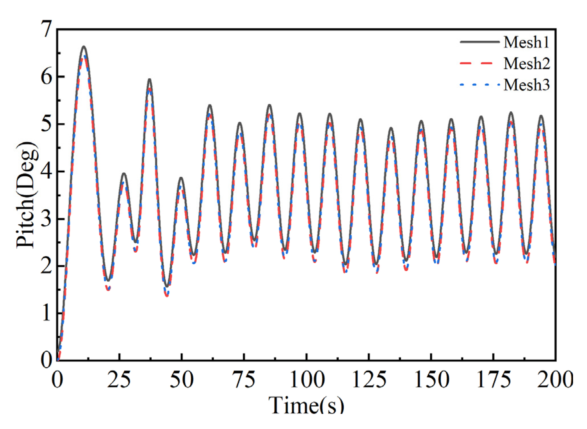
In numerical simulations, the accurate meshing of the rotating region is essential. Accordingly, the mesh around the blades was refined, and three rotating domain mesh resolutions were tested to eliminate mesh-induced differences, as listed in Table 3. The pitch responses computed with the three meshes show that Mesh2 and Mesh3 agree closely with the experimental data. The mesh independence study further confirms that a finer resolution achieves full convergence, and additional refinement yields negligible improvements in the computed aerodynamic coefficients [44]. Balancing computational cost and accuracy, Mesh2 provides the best overall performance, as shown in Figure 8.

3. Comparison of Pitch Performance Between Double-Φ and Single-Φ Rotors

The gyroscopic effect generated by the high-speed rotation of the VAWT rotor significantly influences the platform pitch motion. To mitigate excessive pitch responses, structural modifications of the rotor are introduced in this study, and their effects on the platform’s dynamic behavior are analyzed. The simulations are conducted under combined wind–wave conditions to ensure that the observed response represents realistic sea states.

3.1. Parameters of the FOWT

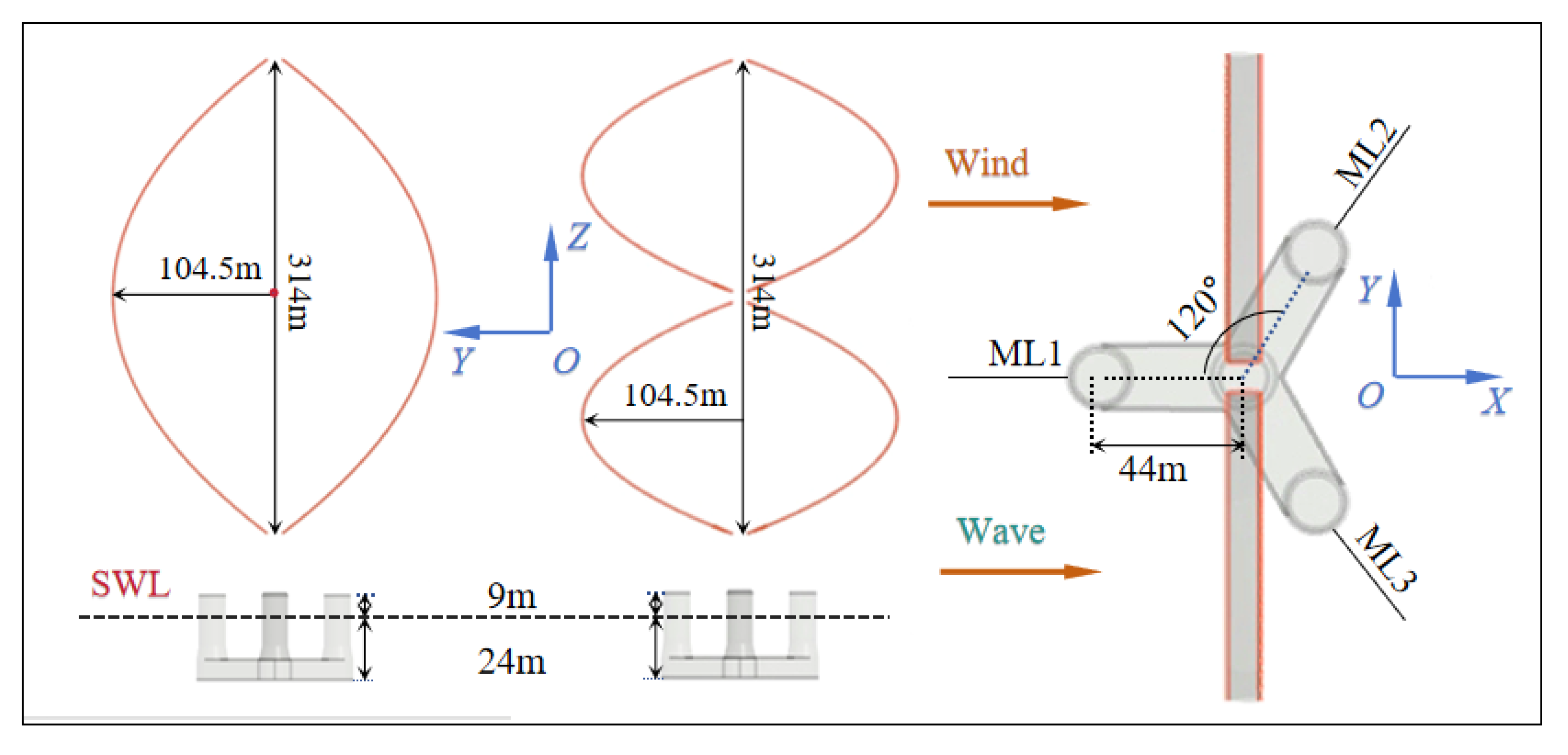
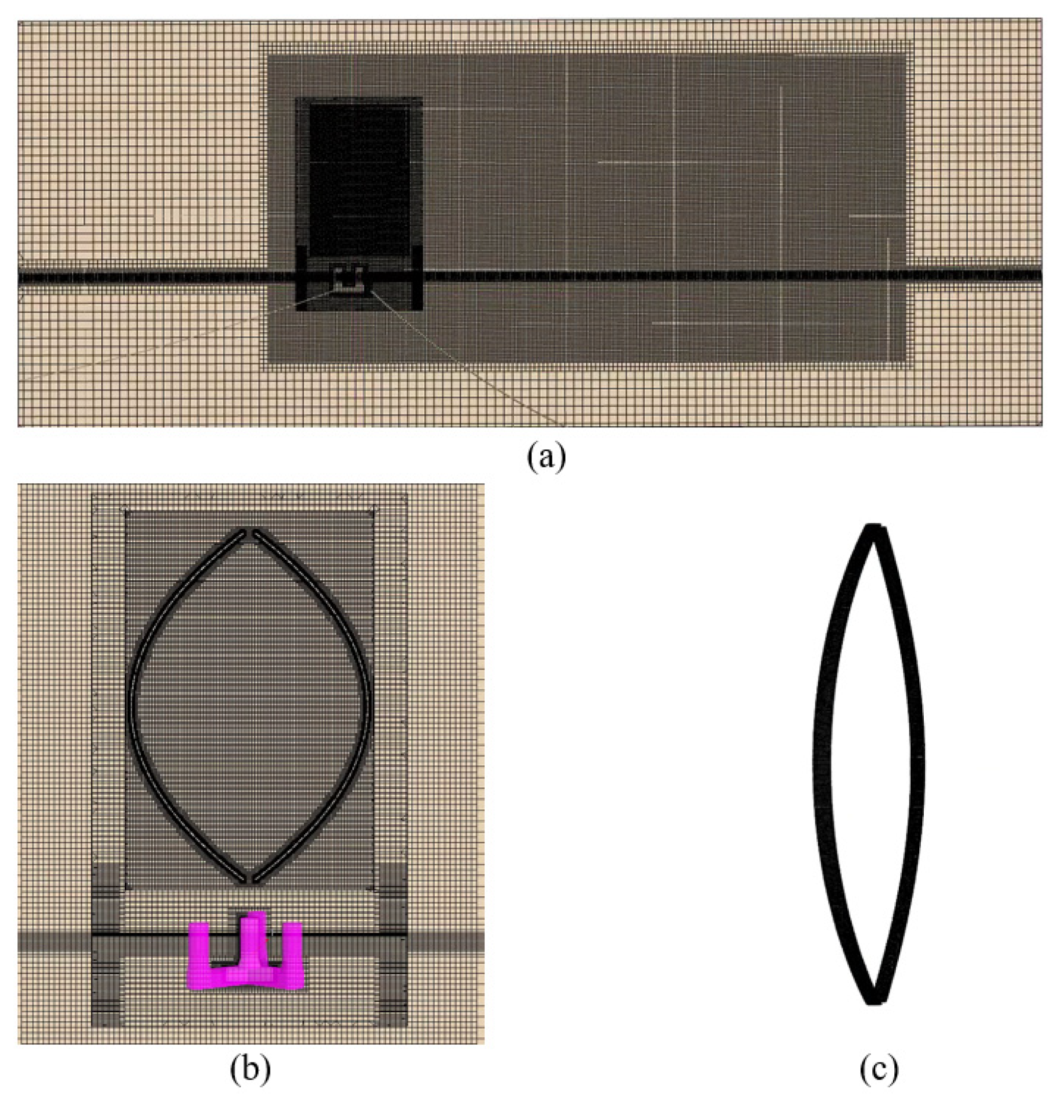
The subject of this study is a 10 MW vertical axis wind turbine (VAWT). Its overall configuration and semi-submersible supporting platform are illustrated in Figure 9, and the main design parameters are listed in Table 4. The selected floating support structure is an OO-Star semi-submersible platform, with key parameters summarized in Table 5 [51]. From this section onward, as shown in Figure 10, the mesh configuration of the single-Φ semi-submersible vertical axis wind turbine (FOVWT) is presented. The mesh generation and boundary condition settings are kept consistent with those described in the preceding validation study. The mesh size is scaled proportionally with the rotor radius to ensure computational accuracy and geometric similarity.
The mooring system of the OO-Star semi-submersible FOWT consists of three mooring lines, with an angle of 120° between any two adjacent lines. The wave direction is aligned with the positive X-axis, and the detailed parameters of the mooring system are provided in Table 6.
To ensure computational accuracy and similarity for turbines of different sizes, the mesh and computational domain are scaled proportionally to the rotor radius. Taking the reference case with a rotor radius of Rref = 63m as a baseline, the radius of the single-rotor configuration is 104.5 m, resulting in a scale factor of s = 1.66. For the double-rotor configuration, the radius is 52.25 m, corresponding to a scale factor of s = 0.83.
Accordingly, the length, width, and height of the computational domain, as well as the inlet, outlet, and symmetry plane locations, are adjusted proportionally. For example, the domain length in the X-direction is scaled from 1595 m to 2646 m (single-rotor case) or 1323 m (double-rotor case). Both the base size and the cell size of the rotating region are scaled by the same factor.
The refinement criteria for the free surface are kept unchanged, with at least 20 cells per wave height and 80 cells per wavelength in the wave propagation direction. The damping zone length is still taken as one wavelength. The prism layer settings for the boundary layer remain the same as in the reference case (first layer thickness of 0.0018 m, eight layers, growth rate of 1.2, and a total thickness of approximately 0.03 m) to maintain a consistent y+ distribution.

3.2. Suppression Effect of Structural Modification

3.2.1. Simulation Cases

Three representative sea states at a water depth of 330 m are selected for the time-domain simulations. The detailed environmental and operating conditions for all cases are summarized in Table 7.
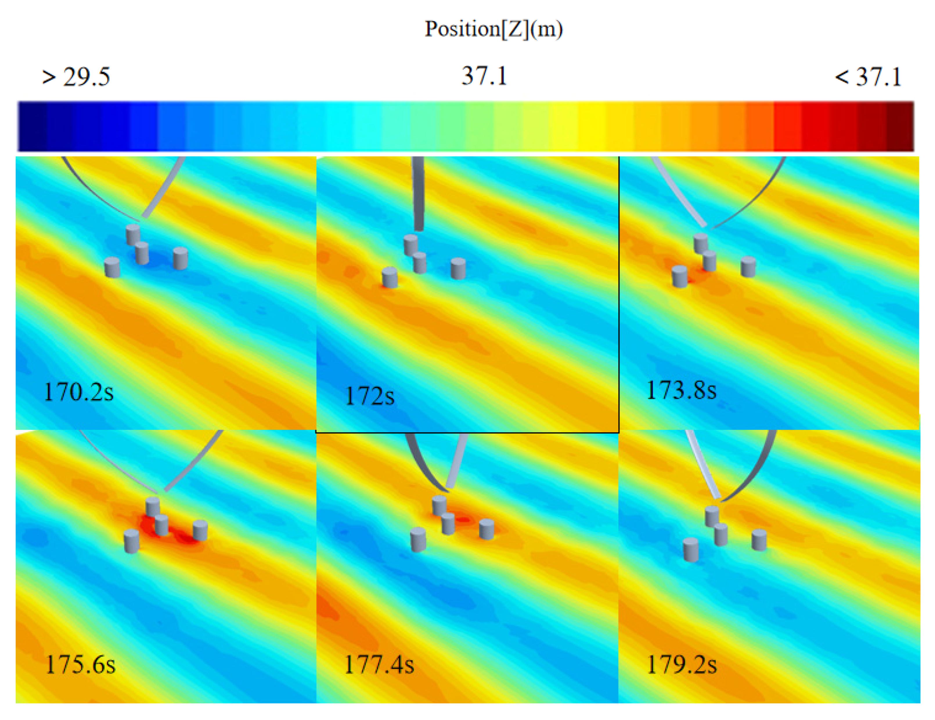
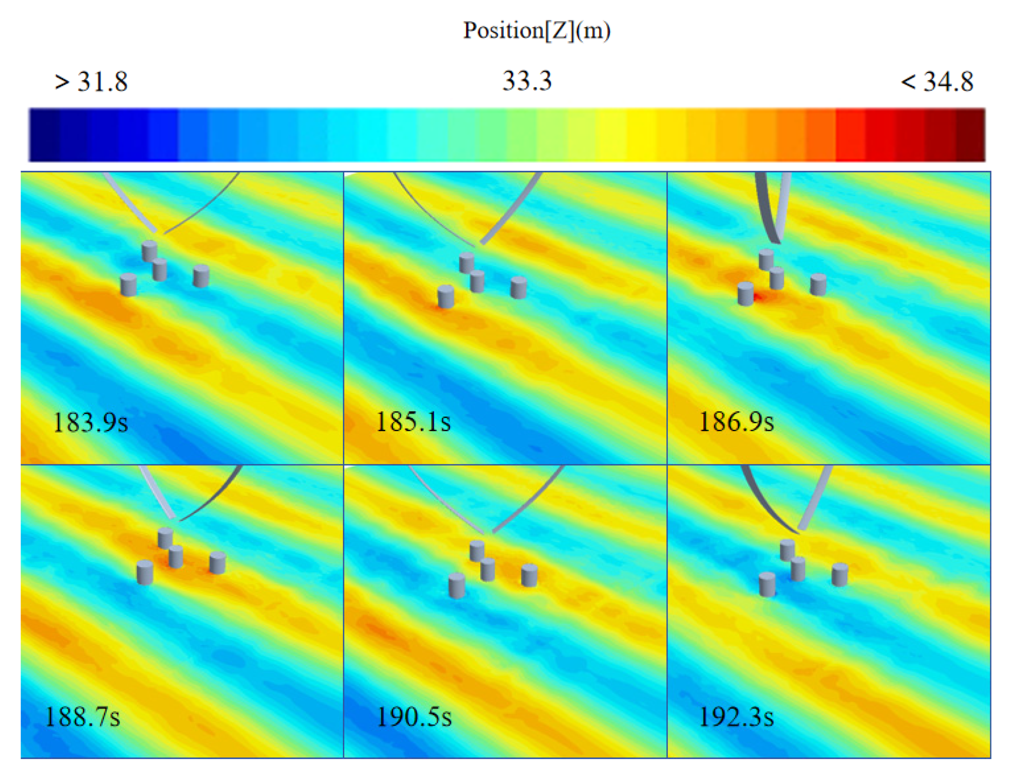
To better illustrate the hydrodynamic environment, Figure 11 and Figure 12 present the wave height contours under periodic wave excitations with peak periods of 12.1 s and 10.73 s, respectively. These contour plots clearly capture the spatiotemporal evolution of the free surface, which serves as the input boundary condition for the subsequent motion response analysis.

3.2.2. Motion Analysis Under Different Operating Conditions

For the future deployment of 10 MW class floating vertical axis wind turbines (FVAWTs) in deep sea regions, the platform inclination induced by the combined wind–wave loading is inevitable, despite the relatively low center of gravity of the semi-submersible foundation. Variations in the pitch angle directly affect the aerodynamic performance of the rotor. Therefore, investigating the motion behavior of the turbine under different sea states and mitigating the pitch motion through structural optimization are the primary objectives of this section.
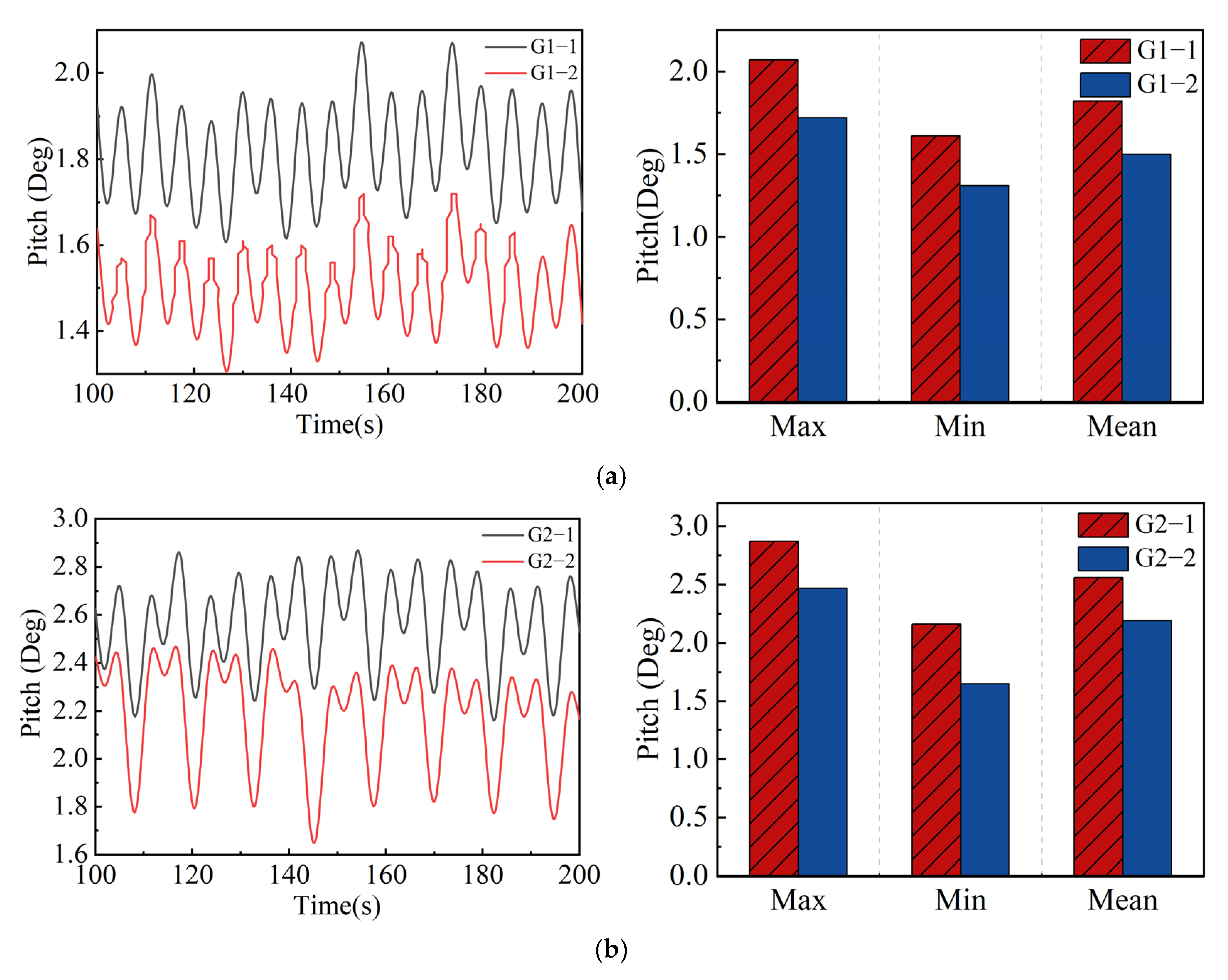
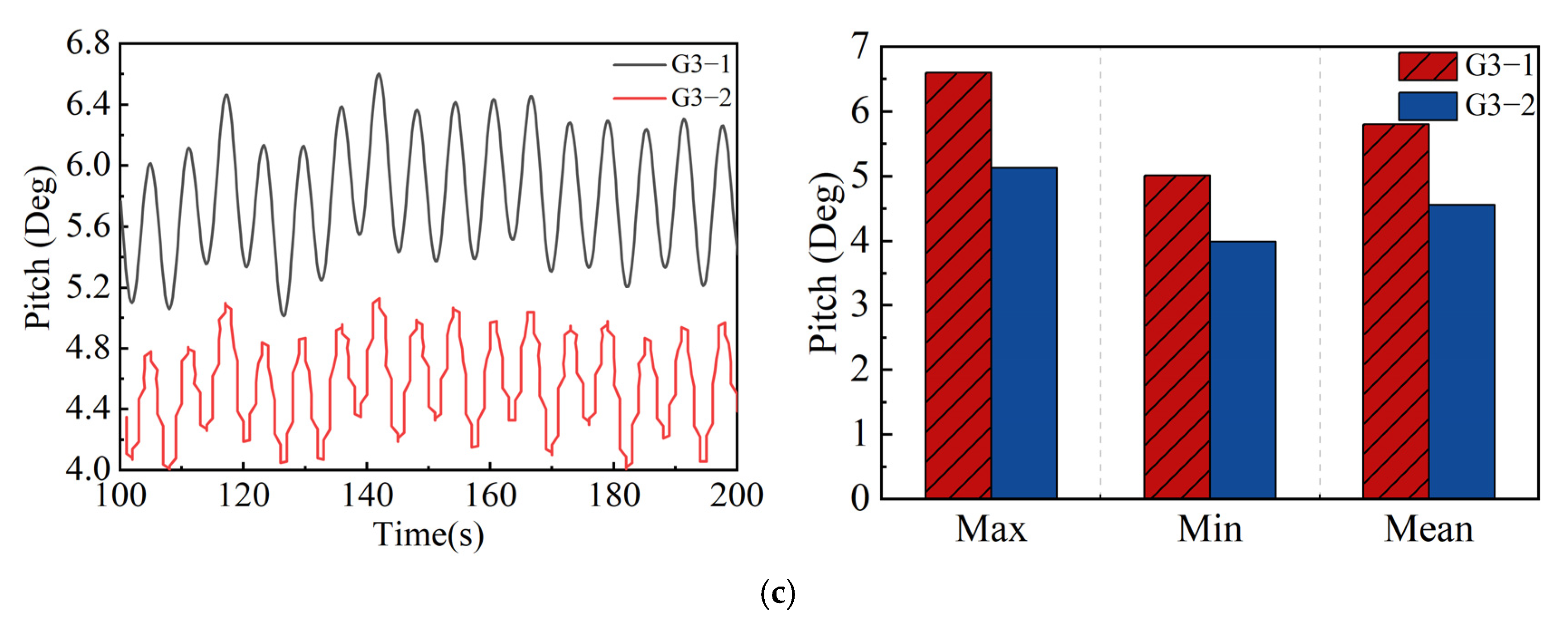
Figure 13 shows the time-domain pitch motion responses of the FOWT system under different regular wave conditions, and Table 8 summarizes the statistical characteristics. The results indicate that the OO-Star semi-submersible FOWT exhibits approximately sinusoidal pitch motion under the combined action of regular waves and turbulent wind. In all three sea states, the double- ϕ configuration significantly reduces the pitch motion compared with the single- ϕ configuration. For instance, under rated condition G2, the maximum pitch angle decreases from 2.87° to 2.47°, corresponding to a reduction of about 14%. Under extreme condition G3, the reduction is even more pronounced, from 6.60° to 5.13° (approximately 22%). These findings suggest that the double- ϕ configuration provides a more effective suppression of the pitch motion under harsh environmental conditions.
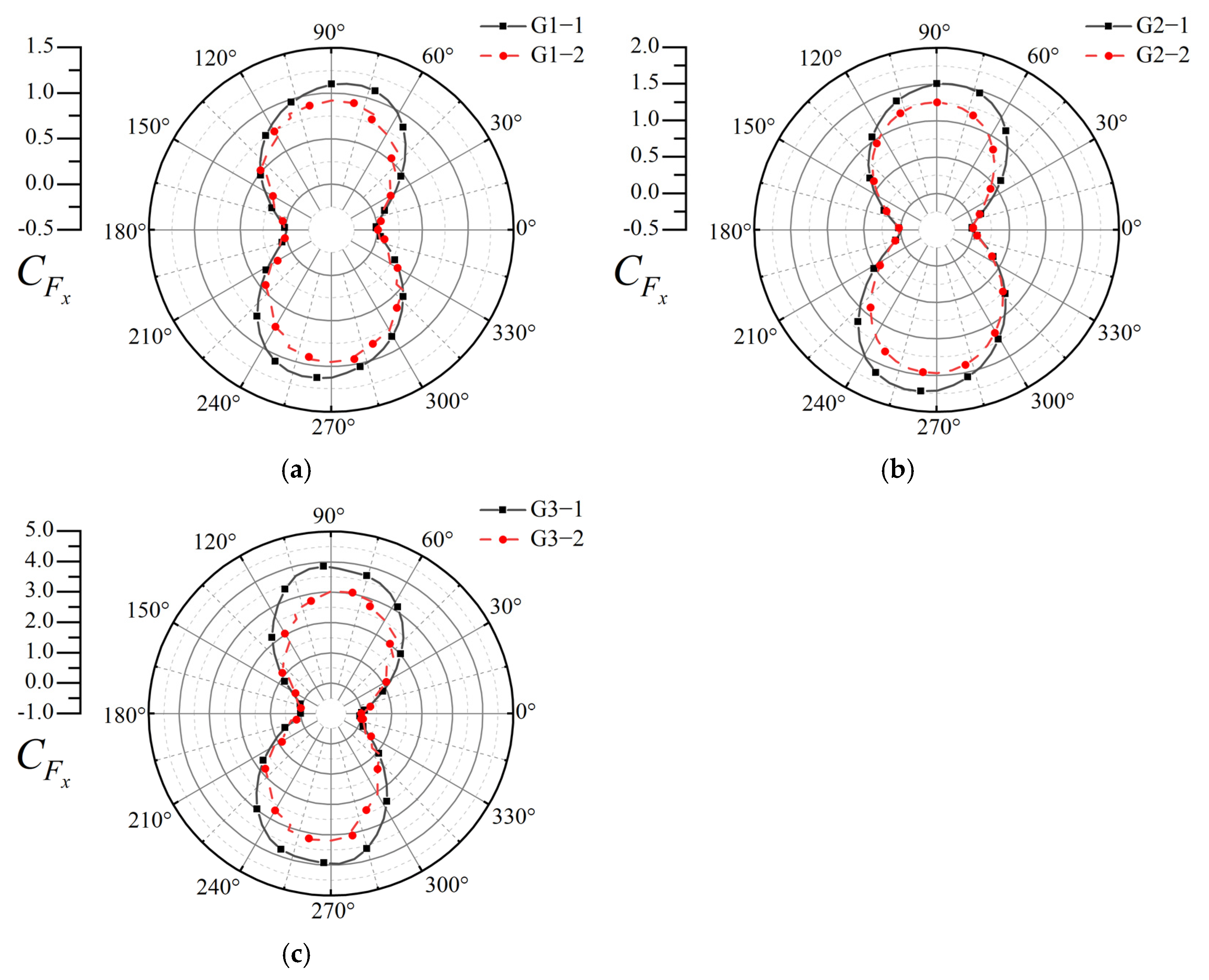
When analyzing the six-degrees-of-freedom (6-DOF) motions of the FOWT, the axial force ( F x ) and lateral force ( F y ) play essential roles. During pitch motion, the wind turbine oscillates along the X-axis about its longitudinal axis, making the axial thrust F x the dominant influencing factor. Figure 14 presents the axial force coefficient ( C F x ) of the single- and double- ϕ rotors over one full revolution (0–360°). Two peaks are observed around 90° and 270°. Compared with the single- ϕ configuration, the double- ϕ design reduces C F x to varying degrees across all sea states. This improvement arises because the air flow is more uniformly distributed across two rotors, and the shorter blade length reduces individual loading, thereby enhancing the overall system stability. Hence, it can be hypothesized that reducing the axial thrust during turbine operation effectively mitigates pitch motion and improves platform stability.

3.3. Suppression Effect of Varying Installation Angle

3.3.1. Simulation Case

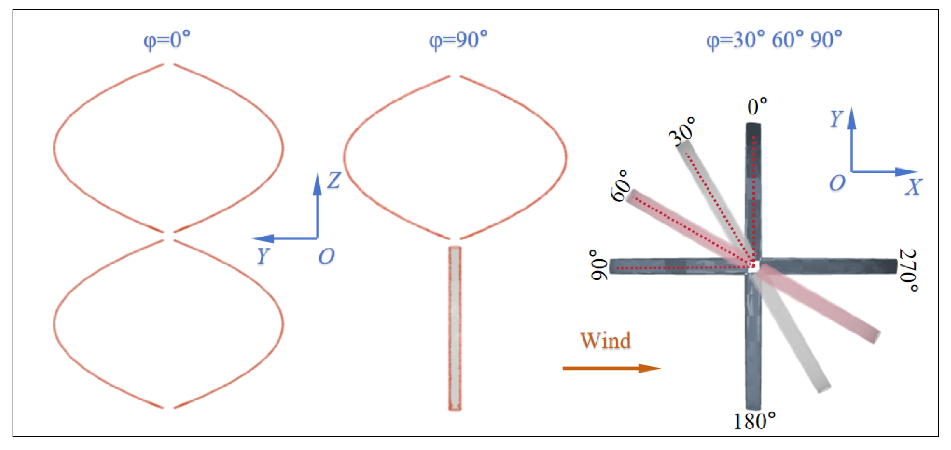
The rated operating condition G2 (wind speed, wave height, and wave period) is selected as the reference sea state. On this basis, a series of simulations are conducted for the double- ϕ VAWT with different blade installation angles. The objective of this analysis is to quantify the influence of several rotor installation angles (30°, 45°, 60°, 75°, and 90°) on the suppression of the pitch motion. The simulation cases are summarized in Table 9, and the schematic of the rotor installation angles for the double- ϕ configuration is shown in Figure 15.

3.3.2. Motion Analysis of Wind Turbines Under Different Installation Angles

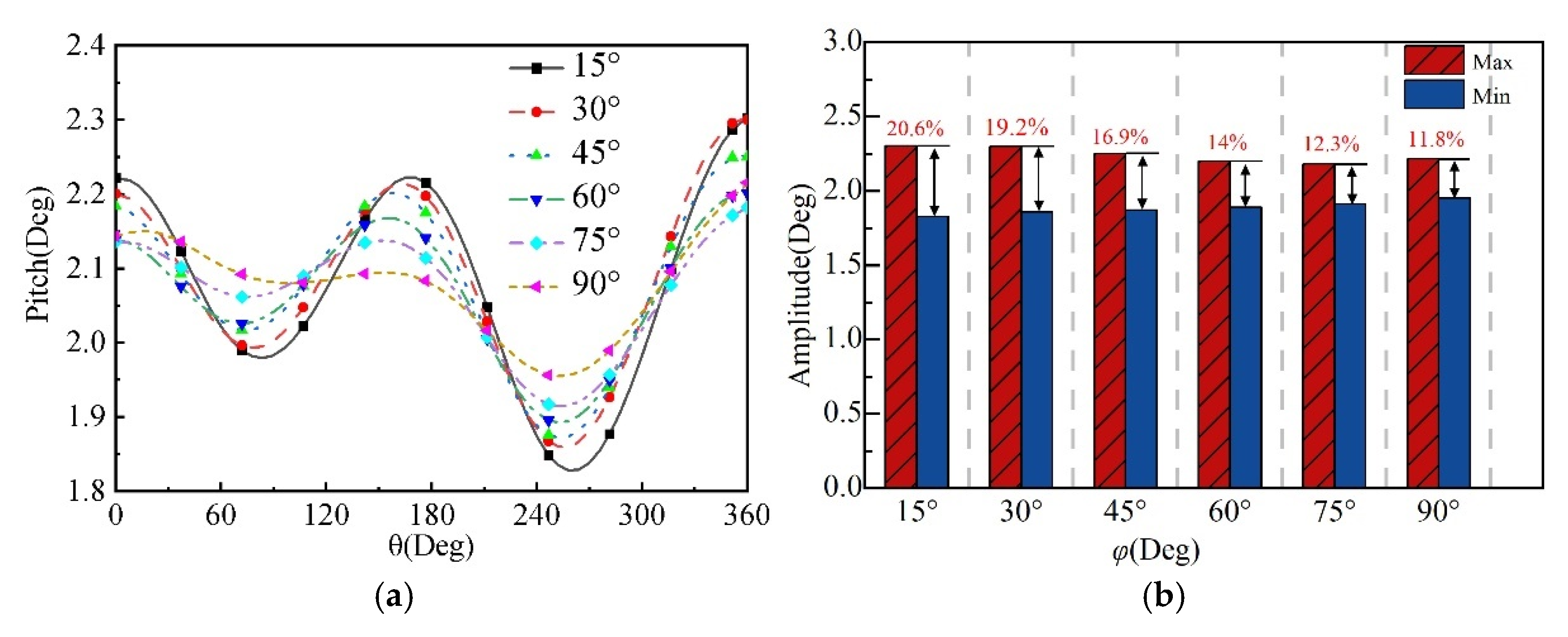
For the double- ϕ floating wind turbine, several installation angles φ (15°, 30°, 45°, 60°, 75°, and 90°) were investigated under the rated operating condition (Case G2) to assess their influence on the pitch motion. The results are shown in Figure 16, including the time-domain response (Figure 16a) and statistical amplitude comparison (Figure 16b). It can be observed that as φ increases, the peak pitch angle decreases, and the oscillation amplitude is significantly reduced, indicating that adjusting the installation angle effectively enhances pitch stability. When φ increases from 15° to 90°, the pitch amplitude decreases from 20.6% to 11.8%, which greatly improves the stability of the system under rated operating conditions. Although the mean pitch angles are similar across different φ values, the case with the φ = 90 exhibits the smallest oscillation amplitude, suggesting superior long-term operational stability.
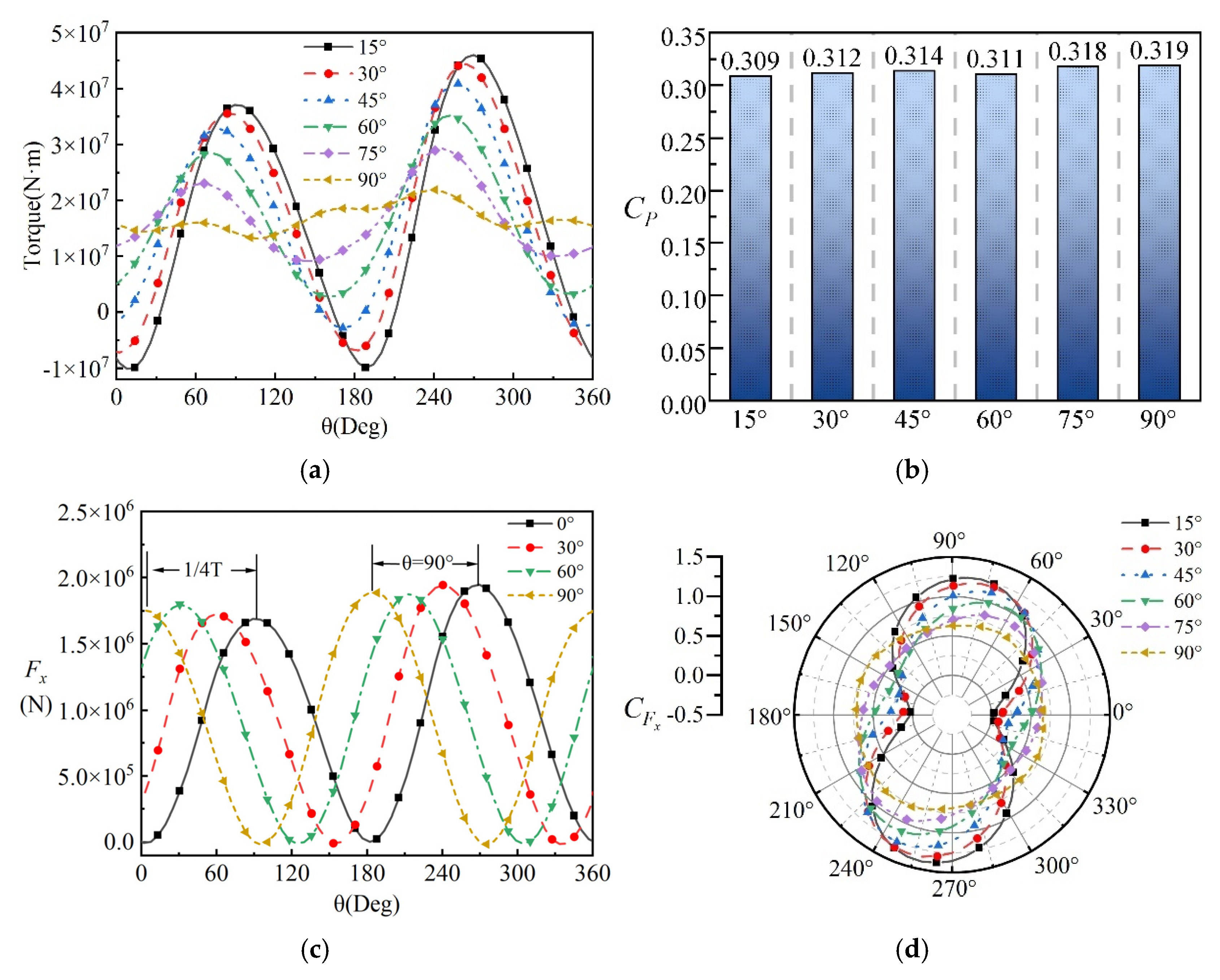
Furthermore, Figure 17 illustrates the turbine torque, power utilization, and axial load characteristics at different installation angles. As shown in Figure 17a, the torque remains stable at approximately 1.68 × 10⁷ N·m with no significant fluctuations, implying reduced load variation and improved operational efficiency. Figure 17b further shows that the power utilization factor remains nearly constant, with slight improvements at larger φ . On the other hand, Figure 17d reveals that at φ = 15 , the turbine experiences alternating axial forces within one cycle. As φ increases, the load becomes more stable. At φ = 90 , the peaks and troughs of the axial force cancel each other out, allowing the turbine to operate under steadier external loads. This effect arises because the double-blade configuration produces two peaks and valleys within one revolution (0–360°), as shown in Figure 17c. The optimal phase alignment at φ = 90 leads to effective cancelation, thereby reducing pitch oscillations.
In summary, optimizing the installation angle not only reduces the pitch amplitude but also mitigates alternating axial loads, significantly enhancing the overall stability of the floating wind turbine system.

3.4. Wake Analysis of the Floating Wind Turbine

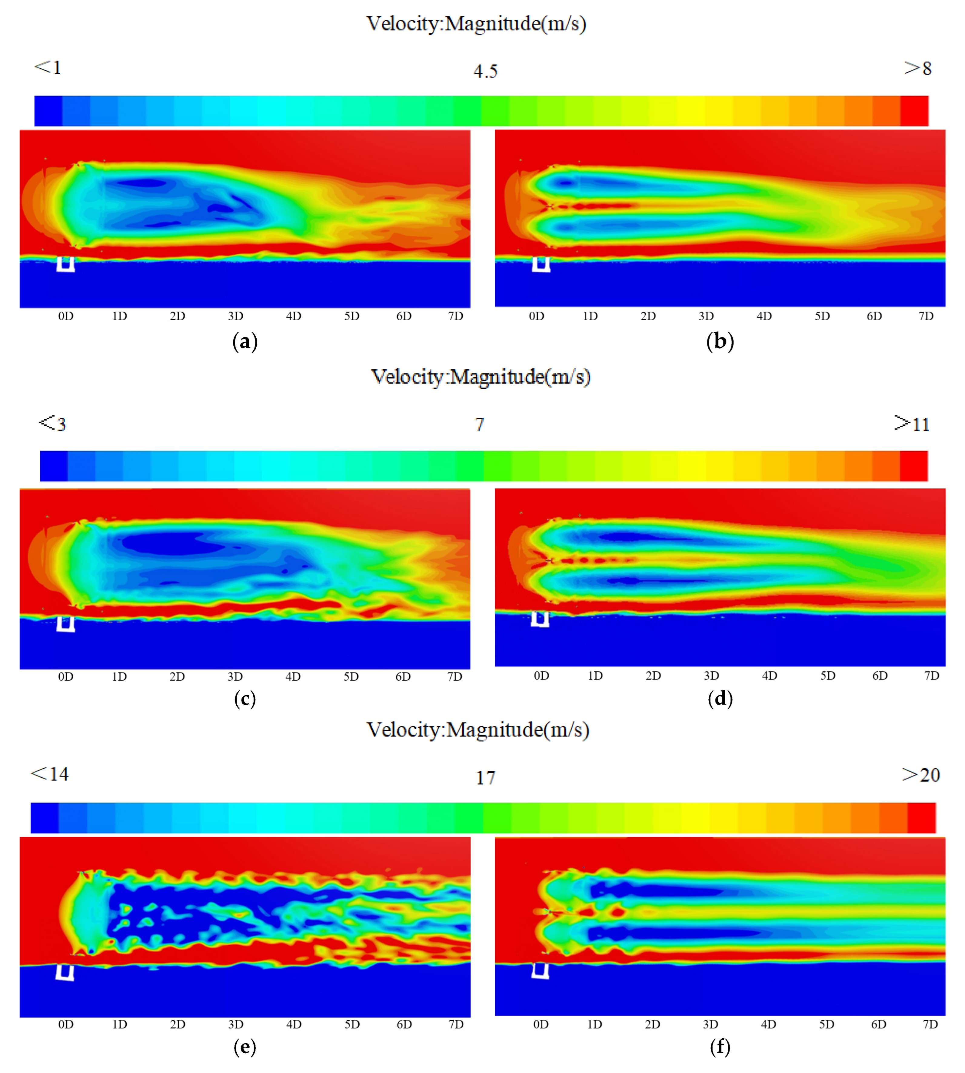
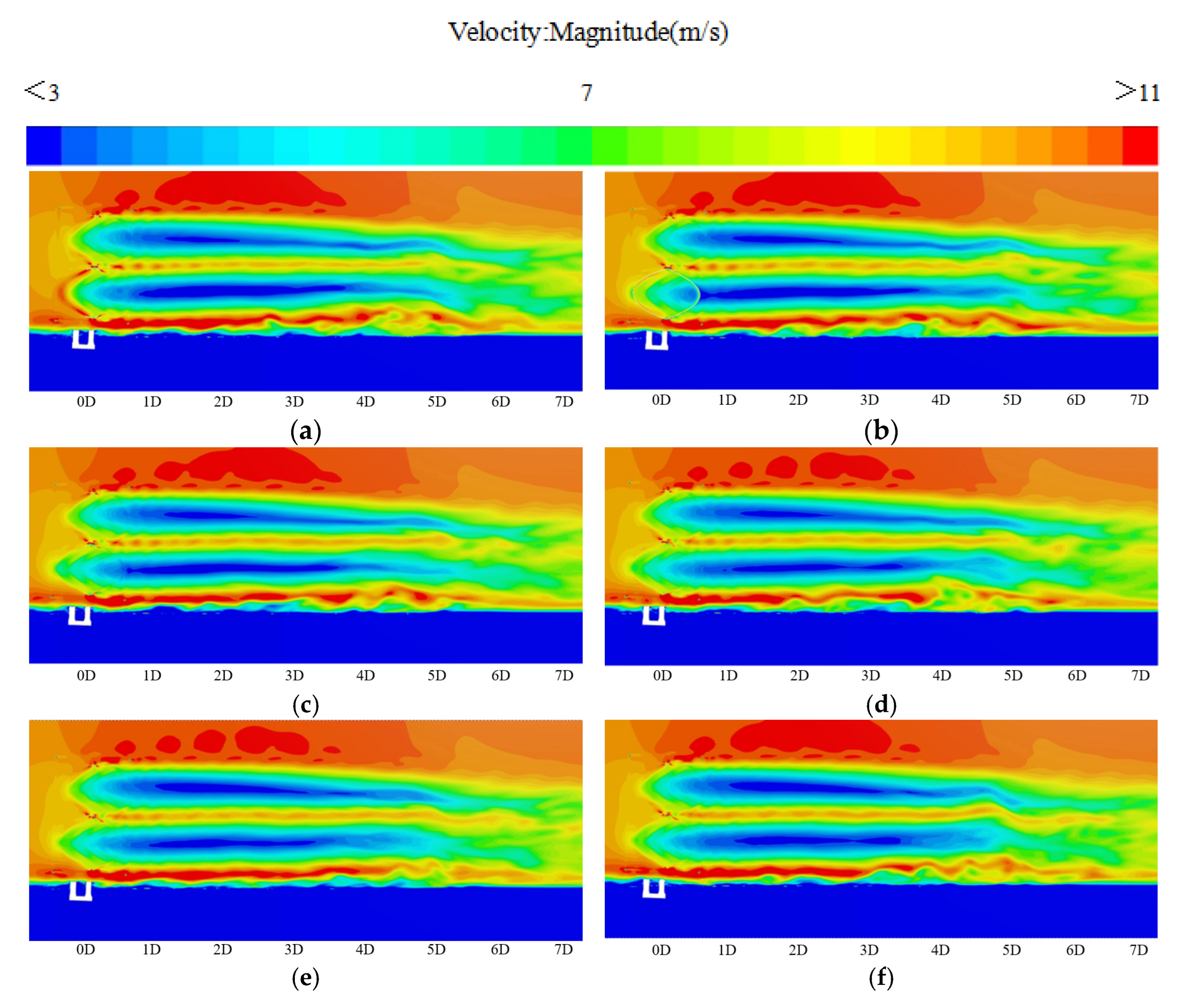
The wake of a floating offshore wind turbine (FOWT) is strongly influenced by the rotor configuration and platform motion. This section examines (i) the impact of the rotor configuration (single- ϕ vs. double- ϕ ) across representative sea states and (ii) the impact of the installation angle φ for the double- ϕ turbine under the rated sea state. This discussion focuses on qualitative features observed from velocity field contours, including the extent of the low-velocity core, wake symmetry, recovery trend, and meandering.

3.4.1. Effect of Rotor Configuration on Wake Characteristics

Figure 18 compares the wake velocity fields for single- ϕ and double- ϕ configurations under G1–G3. In Figure 18a,b (G1), the double- ϕ turbine produces a more continuous and nearly mirror-symmetric low-velocity core, indicating reduced distortion at mild conditions. Under the rated condition (Figure 18c,d), the double- ϕ wake remains more organized; around x 5 D , the shear transition appears smoother and the deep deficit region is shorter than in the single- ϕ case. Under the extreme condition (Figure 18e,f), the single- ϕ wake becomes more chaotic with a low-velocity core persisting farther downstream, whereas the double- ϕ case maintains better symmetry and a visibly shorter deep deficit core. These observations are consistent with the reduced axial thrust and smaller pitch oscillations previously reported for the double- ϕ configuration, which weaken unsteady induction and vortex shedding.

3.4.2. Effect of Installation Angle

To isolate the influence of the installation angle, Figure 19 shows wake velocity fields for the double- ϕ turbine at the rated sea state (G2-2) with φ = 15 ~ 90 . Increasing φ leads to a more symmetric and coherent wake, a shorter deep deficit core, and reduced meandering. For small φ (e.g., 15°), stronger unsteady induction promotes wake expansion and slower centerline recovery; as φ approaches 90 , the deep deficit region visibly contracts and the shear layer becomes smoother. These qualitative trends align with the concurrent reduction in the pitch amplitude and axial thrust at larger φ , indicating improved inflow stability for downstream turbines.

4. Results and Discussion

This study investigates pitch motion amplification in FOVWTs caused by gyroscopic effects and proposes two mitigation schemes: modifying the turbine configuration and optimizing the rotor misalignment angle. The main conclusions are as follows:
1.
Under rated wind–wave conditions, the double- ϕ configuration significantly reduces pitch responses induced by rotor gyroscopic effects. In extreme sea states, the peak pitch angle is reduced by approximately 22%, accompanied by a notable decrease in axial loads, demonstrating that the double- ϕ structure effectively attenuates the amplification of the platform instability caused by gyroscopic moments.
2.
Changing the rotor misalignment angle likewise weakens the gyroscopic effect. As the misalignment increases, the pitch response diminishes. Specifically, when comparing 15° with 90°, the pitch motion amplitude drops from 20.6% to 11.8%, with the turbine power output being nearly unaffected. This is mainly attributed to the cancelation of thrust peaks and troughs within a cycle at larger misalignment angles, which mitigates the periodic load fluctuations driven by gyroscopic effects.
In summary, optimizing the rotor configuration provides an effective pathway to suppress the gyroscopic effect in FOVWTs. These findings offer a reference for enhancing platform stability and extending fatigue life in future FOVWT designs. Future research may focus on developing hybrid control strategies to mitigate the gyroscopic effect. Additionally, a tidal current energy device could be installed beneath the platform as a modular hydrodynamic appendage, utilizing its added mass to enhance system stability and recover part of the energy.

Author Contributions

J.J.: Writing—original draft, Methodology, Data curation, Software. Z.W.: Writing—review and editing, Methodology, Investigation, Funding acquisition, Data curation. W.Z.: Writing—review and editing, Methodology, Supervision. B.Z.: Writing—Methodology, Data curation, Software, review, and editing. All authors have read and agreed to the published version of the manuscript.

Funding

The authors gratefully acknowledge the financial support of the National Natural Science Foundation of China (Grant No. 52171261).

Data Availability Statement

Some or all of the data, models, or code that support the findings of this study are available from the corresponding author upon reasonable request.

Conflicts of Interest

Author Binbin Zhao was employed by the company Zhejiang Yongsheng Technology Co. The remaining authors declare that the research was conducted in the absence of any commercial or financial relationships that could be construed as a potential conflict of interest.

References

  1. Achakulwisut, P.; Erickson, P.; Guivarch, C.; Schaeffer, R.; Brutschin, E.; Pye, S. Global fossil fuel reduction pathways under different climate mitigation strategies and ambitions. Nat. Commun. 2023, 14, 5425. [Google Scholar] [CrossRef] [PubMed]
  2. REN21 M J. Renewables 2023 Global Status Report Collection, Renewables in Energy Supply. 2023. Available online: https://energypedia.info/wiki/Publication_-_Renewables_2023_Global_Status_Report_collection,_Renewables_in_Energy_Supply (accessed on 28 October 2025).
  3. Global Overview, Renewables 2024. Available online: https://www.iea.org/reports/renewables-2024/global-overview (accessed on 28 October 2025).
  4. Desalegn, B.; Gebeyehu, D.; Tamrat, B. Wind energy conversion technologies and engineering approaches to enhancing wind power generation: A review. Heliyon 2022, 8, e11263. [Google Scholar] [CrossRef] [PubMed]
  5. Didane, D.H.; Rosly, N.; Zulkafli, M.F.; Shamsudin, S.S. Performance evaluation of a novel vertical axis wind turbine with coaxial contra-rotating concept. Renew. Energy 2018, 115, 353–361. [Google Scholar] [CrossRef]
  6. Xu, Y.; Yang, K.; Zhao, G. The influencing factors and hierarchical relationships of offshore wind power industry in China. Environ. Sci. Pollut. Res. 2021, 28, 52329–52344. [Google Scholar] [CrossRef]
  7. Zhang, J.; Wang, X.; Liu, Z.; Zhang, Y. A review of platform designs for floating offshore wind turbines. Chin. J. Ship Res. 2024, 19, 21–31. (In Chinese) [Google Scholar] [CrossRef]
  8. Zhang, S.Y.; Tan, G.; Deng, Y.; Zhang, Y.; Wang, Y.; Wang, Z. Vibration mitigation of spar-buoy floating wind turbines using a nonlinear energy sink. Ocean Eng. 2024, 304, 117883. [Google Scholar] [CrossRef]
  9. Wang, B.; Gao, X.; Li, Y.; Liu, L.; Li, H. Dynamic response analysis of a semi-submersible floating wind turbine based on different coupling methods. Ocean Eng. 2024, 297, 116948. [Google Scholar] [CrossRef]
  10. Ren, Y.; Shi, W.; Venugopal, V.; Zhang, L.; Li, X. Experimental study of tendon failure analysis for a TLP floating offshore wind turbine. Appl. Energy 2024, 358, 122633. [Google Scholar] [CrossRef]
  11. Sirigu, M.; Ghigo, A.; Petracca, E.; Giorgi, G.; Bracco, G. Fatigue assessment of a new concept for a floating barge with pendulum for offshore wind turbines in MOST. J. Phys. Conf. Ser. 2024, 2767, 62024. [Google Scholar] [CrossRef]
  12. Edwards, E.C.; Holcombe, A.; Brown, S.; Ransley, E.; Hann, M.; Greaves, D. Evolution of floating offshore wind platforms: A review of at-sea devices. Renew. Sustain. Energy Rev. 2023, 183, 113416. [Google Scholar] [CrossRef]
  13. Jeong, M.; Loth, E.; Qin, C.; Selig, M.; Johnson, N. Aerodynamic rotor design for a 25 MW offshore downwind turbine. Appl. Energy 2024, 353, 122035. [Google Scholar] [CrossRef]
  14. Koragappa, P.; Verdin, P.G. Design and optimisation of a 20 MW offshore wind turbine blade. Ocean Eng. 2024, 305, 117975. [Google Scholar] [CrossRef]
  15. Mehta, M.; Zaaijer, M.; von Terzi, D. Drivers for optimum sizing of wind turbines for offshore wind farms. Wind. Energy Sci. 2024, 9, 141–163. [Google Scholar] [CrossRef]
  16. Huanqiang, Z.; Xiaoxia, G.; Hongkun, L.; Qiansheng, Z.; Xiaoxun, Z.; Yu, W.; Fei, Z. Investigation of a new 3D wake model of offshore floating wind turbines subjected to the coupling effects of wind and wave. Appl. Energy 2024, 365, 123189. [Google Scholar] [CrossRef]
  17. Wenfeng, L.; Zhenzhou, Z.; Yige, L.; Huiwen, L.; Shangshang, W.; Ali, K.; Guodan, D.; Yan, L.; Yuanzhuo, M. Investigation of dynamic wake model of a floating offshore wind turbine under heave, surge and pitch motion. Renew. Energy 2025, 254, 123665. [Google Scholar] [CrossRef]
  18. Wang, T.; Cai, C.; Gao, X.; Sun, X.; Guo, N.; Hu, Z.; Zheng, J.; Wang, D.; Peng, C.; Li, Q. Study on wake interactions of tandem floating offshore wind turbines under different yaw conditions using actuator line method. Energy 2025, 337, 138486. [Google Scholar] [CrossRef]
  19. Mian, H.; Messmer, T.; Stoevesandt, B.; Siddiqui, M. Coherent flow structures in the wake of a model floating wind turbine under pitch and roll motions. Energy 2025, 335, 138212. [Google Scholar] [CrossRef]
  20. Abbas, N.J.; Jasa, J.; Zalkind, D.S.; Wright, A.; Pao, L. Control co-design of a floating offshore wind turbine. Appl. Energy 2024, 353, 122036. [Google Scholar] [CrossRef]
  21. Du, X.; Liang, J.; Muro, J.L.; Qian, G.; Burlion, L.; Bilgen, O. Development of a control co-design optimization framework with aeroelastic-control coupling for floating offshore wind turbines. Appl. Energy 2024, 372, 123728. [Google Scholar] [CrossRef]
  22. Liu, J.; Cai, C.; Song, D.; Zhong, X.; Shi, K.; Chen, Y.; Cheng, S.; Huang, Y.; Jiang, X.; Li, Q. Nonlinear model predictive control for maximum wind energy extraction of semi-submersible floating offshore wind turbine based on simplified dynamics model. Energy 2024, 311, 133356. [Google Scholar] [CrossRef]
  23. Ghigo, A.; Faraggiana, E.; Giorgi, G.; Mattiazzo, G.; Bracco, G. Floating Vertical Axis Wind Turbines for offshore applications among potentialities and challenges: A review. Renew Sustain. Energy Rev. 2024, 193, 114302. [Google Scholar] [CrossRef]
  24. Bhutta, M.M.A.; Hayat, N.; Farooq, A.U.; Ali, Z.; Jamil, S.R.; Hussain, Z. Vertical axis wind turbine—A review of various configurations and design techniques. Renew Sustain. Energy Rev. 2012, 16, 1926–1939. [Google Scholar] [CrossRef]
  25. Borg, M.; Collu, M.; Kolios, A. Offshore floating vertical axis wind turbines, dynamics modelling state of the art. Part II: Mooring line and structural dynamics. Renew Sustain. Energy Rev. 2014, 39, 1226–1234. [Google Scholar] [CrossRef]
  26. Liu, Q.; Huang, H.; Iglesias, G.; Wang, J.; Bashir, M. Fully coupled aero-hydrodynamic analysis of floating vertical axis wind turbines in staggered configurations. Energy 2025, 337, 138679. [Google Scholar] [CrossRef]
  27. Martin, J.B. Plasticity: Fundamentals and General Results; McGraw-Hill: Columbus, OH, USA, 1975. [Google Scholar]
  28. Al-Solihat, M.K.; Nahon, M.; Behdinan, K. Dynamic modeling and simulation of a spar floating offshore wind turbine with consideration of the rotor speed variations. J. Dyn. Syst. Meas. Control 2019, 141, 081014. [Google Scholar] [CrossRef]
  29. Høeg, C.E.; Zhang, Z. The influence of gyroscopic effects on dynamic responses of floating offshore wind turbines in idling and operational conditions. Ocean Eng. 2021, 227, 108712. [Google Scholar] [CrossRef]
  30. Greenwood, D.T. Principles of Dynamics; Prentice-Hall: Englewood Cliffs, NJ, USA, 1965. [Google Scholar]
  31. Pezeshki, H.; Pavlou, D.; Adeli, H.; Siriwardane, S. Gyroscopic effects of the spinning rotor-blades assembly on dynamic response of offshore wind turbines. J. Wind Eng. Ind. Aerodyn. 2024, 247, 105698. [Google Scholar] [CrossRef]
  32. Liu, Z.; Tu, Y.; Wang, W.; Qian, G. Numerical analysis of a catenary mooring system attached by clump masses for improving the wave-resistance ability of a spar buoy-type floating offshore wind turbine. Appl. Sci. 2019, 9, 1075. [Google Scholar] [CrossRef]
  33. Zhang, H.; Wen, B.; Tian, X.; Li, X.; Dong, Y.; Wang, M.; Peng, Z. Experimental study on mitigating vibration of floating offshore wind turbine using tuned mass damper. Ocean Eng. 2023, 288, 115974. [Google Scholar] [CrossRef]
  34. Zheng, X.; Zhang, T.; Hu, Z.; Ma, G. Study on characteristics and optimal layout of components in shallow water mooring system of floating wind turbine. Appl. Sci. 2022, 12, 10137. [Google Scholar] [CrossRef]
  35. Wang, J.; Li, H.; Zhang, J.; Guan, D.; Chen, H.; Lu, T. Experiment investigations of pitch motions for a semi-submersible wind turbine with the passive gyro stabilizers. Appl. Ocean Res. 2025, 163, 104757. [Google Scholar] [CrossRef]
  36. Cayuela-Padilla, S.; M’zOughi, F.; Garrido, I.; Garrido, A.J. Design and stability analysis of a new six-floater oscillating water column-based floating offshore wind turbine platform. Sci. Rep. 2024, 14, 16191. [Google Scholar] [CrossRef]
  37. Zhao, H.; Wei, K.; Yang, W. Further study of heave plate designs for enhancing motion control of floating offshore wind turbines. Ocean Eng. 2025, 327, 121016. [Google Scholar] [CrossRef]
  38. Salic, T.; Charpentier, J.F.; Benbouzid, M.; Le Boulluec, M. Control strategies for floating offshore wind turbine: Challenges and trends. Electronics 2019, 8, 1185. [Google Scholar] [CrossRef]
  39. Ha, K.; Truong, H.V.A.; Dang, T.D.; Ahn, K.K. Recent control technologies for floating offshore wind energy system: A review. Int. J. Precis. Eng. Manuf. Green Technol. 2021, 8, 281–301. [Google Scholar] [CrossRef]
  40. Ai, S.; Su, J.; Meng, W.; Yan, Y. Integrated control of blade pitch and generator speed for floating wind turbines. Ocean Eng. 2024, 300, 117080. [Google Scholar] [CrossRef]
  41. Wang, X.; Xiao, Y.; Cai, C.; Wu, X.; Zhang, Y.; Kong, D.; Liu, J.; Sun, X.; Zhong, X.; Li, Q. Cyclic pitch control for aerodynamic load reductions of floating offshore wind turbines under pitch motions. Energy 2024, 309, 132945. [Google Scholar] [CrossRef]
  42. Wang, S.; Xiao, J.; Chen, S.; Ji, R.; Wang, K. Rotational speed prediction for rated power operation of a horizontal axis tidal turbine under surging motion conditions. Ocean Eng. 2025, 339, 122206. [Google Scholar] [CrossRef]
  43. Yin, M.; Ji, R.; Zhu, R.; Xu, S.; Sun, K.; Zhang, J.; Zhang, Y.; Reabroy, R. Performance and wake prediction of a ducted tidal stream turbine in yaw misalignment using the lattice Boltzmann method. Energy Convers. Manag. 2026, 347, 120574. [Google Scholar] [CrossRef]
  44. Abdallah, A.; William, M.A.; Moharram, N.A.; Zidane, I.F. Boosting H-Darrieus vertical axis wind turbine performance: A CFD investigation of J-Blade aerodynamics. Results Eng. 2025, 27, 106358. [Google Scholar] [CrossRef]
  45. Tran, T.T.; Kim, D.-H. Fully coupled aero-hydrodynamic analysis of a semi-submersible FOWT using a dynamic fluid body interaction approach. Renew. Energy 2016, 92, 244–261. [Google Scholar] [CrossRef]
  46. Goupee, A.J.; Koo, B.J.; Kimball, R.W.; Lambrakos, K.F.; Dagher, H.J. Experimental comparison of three floating wind turbine concepts. J. Offshore Mech. Arct. Eng. 2014, 136, 020906. [Google Scholar] [CrossRef]
  47. CD-adapco. STAR-CCM+, v13.02; Documentation; CD-adapco: Melville, NY, USA, 2018. [Google Scholar]
  48. Dong, K.; Wang, X.; Zhang, D.; Liu, L.; Feng, D. CFD Research on the Hydrodynamic Performance of Submarine Sailing near the Free Surface with Long-Crested Waves. J. Mar. Sci. Eng. 2022, 10, 90. [Google Scholar] [CrossRef]
  49. Zhao, B.; Jiang, H.; Sun, J.; Zhang, D. Research on the Hydrodynamic Performance of a Pentamaran in Calm Water and Regular Waves. Appl. Sci. 2023, 13, 4461. [Google Scholar] [CrossRef]
  50. Wang, S.; Tang, J.; Li, C.; Ji, R.; Fernandez-Rodriguez, E. Performance evaluation and fast prediction of a pitched horizontal-axis tidal turbine under wave-current conditions using a variable-speed control strategy. J. Fluids Struct. 2025, 133, 104265. [Google Scholar] [CrossRef]
  51. Huang, H.; Liu, Q.; Yue, M.; Miao, W.; Wang, P.; Li, C. Fully coupled aero-hydrodynamic analysis of a biomimetic fractal semi-submersible floating offshore wind turbine under wind-wave excitation conditions. Renew. Energy 2023, 203, 280–300. [Google Scholar] [CrossRef]
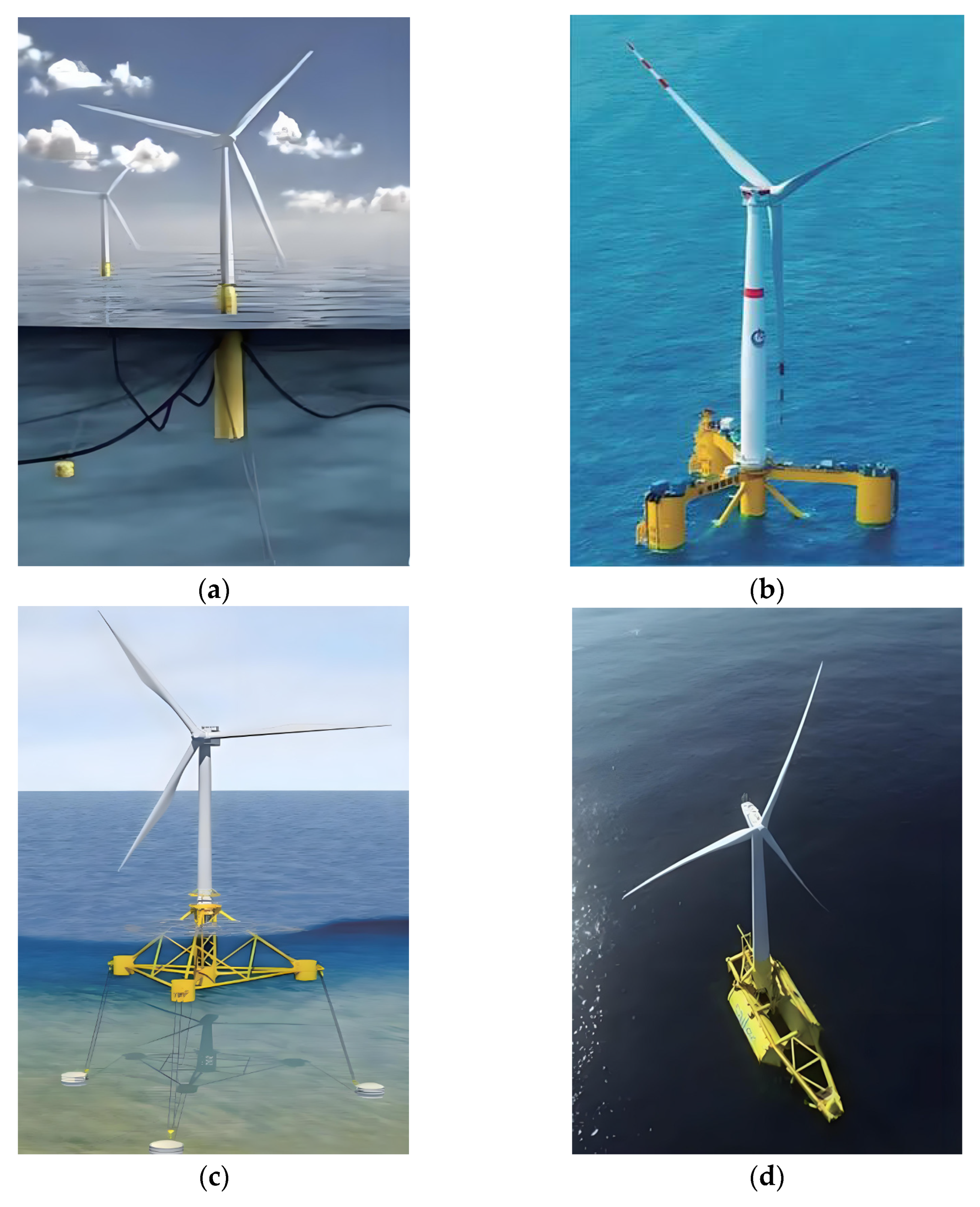
Figure 1. Four typical platform types for floating offshore wind turbines (FOWTs): (a) Norway Hywind I; (b) China National Offshore Oil Corporation “Guanlan”; (c) France PGL; and (d) Spain DemoSATH.
Energies 18 05847 g001
Figure 2. A schematic of the gyroscopic effect in the FOVWT. (The blue dashed line denotes the rotor region, the blue solid line denotes the magnified rotor region, and the red dashed line denotes the gyroscopic effect trajectory).
Energies 18 05847 g002
Figure 3. Single- ϕ semi-submersible FOVWT model. (a) Prototype configuration; (b) simplified model.
Energies 18 05847 g003
Figure 4. The coordinate system of the floating offshore VAWT system.
Energies 18 05847 g004
Figure 5. CFD flowchart for computing aerodynamic loads on the FOVWT and the resulting platform motion response [45].
Energies 18 05847 g005
Figure 6. Computational domain and mesh configuration of the NREL 5 MW OC4 FOWT: (a) domain geometry, boundary conditions, and dimensions; mesh distribution in the entrance, flow–structure, and outlet regions; (b) detailed view of overset and sliding mesh boundaries, multi-level refinement; (c) semi-submersible platform, and rotor model.
Energies 18 05847 g006
Figure 7. Validation of platform surge, heave, and pitch responses.
Energies 18 05847 g007
Figure 8. Pitch response under three mesh configurations.
Energies 18 05847 g008
Figure 9. A schematic of the ϕ -type vertical axis FOWT rotor and semi-submersible platform.
Energies 18 05847 g009
Figure 10. Mesh of the semi-submersible FOVWT: (a) overall view; (b) rotor–platform mesh (Purple denotes the location of the platform); and (c) rotor mesh.
Energies 18 05847 g010
Figure 11. Wave field evolution around the floating wind turbine at T P = 12.1 s.
Energies 18 05847 g011
Figure 12. Wave field evolution around the floating wind turbine at T P = 10.73 s.
Energies 18 05847 g012
Figure 13. Time-domain pitch motion responses of the FOWT under different sea states. (a) G1 operating condition; (b) G2 operating condition; (c) G3 operating condition.
Energies 18 05847 g013aEnergies 18 05847 g013b
Figure 14. Axial thrust coefficient C F x over one rotor revolution under different sea states. (a) G1– C F x ; (b) G2– C F x ; and (c) G3– C F x .
Energies 18 05847 g014
Figure 15. Schematic of rotor installation angles for the double- ϕ VAWT.
Energies 18 05847 g015
Figure 16. Pitch motion of the FOWT under different installation angles: (a) time-domain response and (b) statistical amplitude.
Energies 18 05847 g016
Figure 17. Aerodynamic and load characteristics under different installation angles: (a) rotor torque; (b) power coefficient; (c) thrust; and (d) thrust coefficient.
Energies 18 05847 g017
Figure 18. Wake velocity fields under different sea states and rotor configurations: (a) G1-1, single- ϕ ; (b) G1-2, double- ϕ ; (c) G2-1, single- ϕ ; (d) G2-2, double- ϕ ; (e) G3-1, single- ϕ ; and (f) G3-2, double- ϕ .
Energies 18 05847 g018
Figure 19. Wake velocity fields of the double- ϕ FOWT at different installation angles under the rated condition (G2-2): (a) φ = 15 ; (b) φ = 30 ; (c) φ = 45 ; (d) φ = 60 ; (e) φ = 75 ; and (f) φ = 90 .
Energies 18 05847 g019
Table 1. Definitions of nondimensional parameters used for performance evaluation of the VAWT.
SymbolParameter
V A   (m/s)Free-stream wind velocity
S   ( m 2 )Rotor swept area
R   (m)Rotor radius
Z Number of blades
ω   (rad/s)Angular velocity
θ   (°)Blade installation angle
F x   (N)Axial thrust
F y   (N)Lateral force
λ Tip speed ratio
Q   (Nm)Rotor torque
ρ /(kg/m3)Air density
Table 2. Comparison of platform natural periods.
ParameterNumerical ResultReference Value [46]Error
Surge1191135.3%
Sway1141121.7%
Heave17.917.52.3%
Roll26.226.92.6%
Pitch27.526.82.6%
Yaw79.882.33.0%
Table 3. Three different grid sizes.
CaseFluid Region
(Million)
Rotating Region
(Million)
Total Grid
(Million)
Mesh1340650990
Mesh24208001220
Mesh34209801500
Table 4. Main parameters of the VAWT-based FOWT used in this study.
ItemValue
Cut-in wind speed (m/s)4
Cut-out wind speed (m/s)25
Rated wind speed (m/s)10
Rotor speed (rad/s)0.508
Blade airfoilNACA0018
Single- ϕ configurationRotor diameter (m)209
Rotor height (m)314
Blade chord length (m)10.45
Number of blades2
Double- ϕ configurationRotor diameter (m)104.5
Rotor height (m)157
Blade chord length (m)5.225
Number of blades2
Table 5. Main parameters of the semi-submersible platform.
ItemValue
Pontoon angle (°)120
Central column height (m)33
Side column height (m)32
Mass (kg)2.360 × 10⁷
Center of gravity (x, y, z) (m)(−0.02, 0.00, −7.94)
Center of buoyancy (x, y, z) (m)(0.00, 0.00, −14.24)
Roll moment of inertia, Ixx (kg·m2)2.670 × 10¹⁰
Pitch moment of inertia, Iyy (kg·m2)2.660 × 10¹⁰
Yaw moment of inertia, Izz(kg·m2)1.640 × 10¹⁰
Displacement volume (m3)2.350 × 10⁴
Draft (m)22
Table 6. Parameters of the mooring system.
ItemValue
Number of mooring lines3
Angle between adjacent lines (°)120
Length of each mooring line (m)1259
Mooring radius (m)1230
Water depth (m)333.27
Mass per unit length (kg·m)108.36
Axial stiffness (N/m)902,000
Table 7. Operating conditions of the wind turbine.
CaseWave Height (m)Peak Period (s)Wind Speed (m/s)Turbine Configuration
G1-13.0210.738Single- Φ
G1-2Double- Φ
G2-17.5812.110Single- Φ
G2-2Double- Φ
G3-17.5812.120Single- Φ
G3-2Double- Φ
Table 8. Statistical characteristics of platform pitch motion.
CasePitch (°)
MaxMinMean
G1-12.071.611.82
G1-21.721.311.50
G2-12.872.162.56
G2-22.471.652.19
G3-16.605.015.80
G3-25.133.994.56
Table 9. Simulation case for the double- ϕ wind turbine with different installation angles.
CaseWave Height (m)Period (s)Wind Speed (m/s)Double-Φ VAWT Installation Angles
G2-27.5812.11015° 30° 45° 60° 75° 90°
Disclaimer/Publisher’s Note: The statements, opinions and data contained in all publications are solely those of the individual author(s) and contributor(s) and not of MDPI and/or the editor(s). MDPI and/or the editor(s) disclaim responsibility for any injury to people or property resulting from any ideas, methods, instructions or products referred to in the content.