Article

Metaheuristic-Based Control Parameter Optimization of DFIG-Based Wind Energy Conversion Systems Using the Opposition-Based Search Optimization Algorithm

by
Kavita Behara
1,* and
Ramesh Kumar Behara
2
1
Department of Electrical Engineering, Mangosuthu University of Technology, Durban 4031, South Africa
2
Electrical Engineering, Mondi Paper, Durban 4052, South Africa
*
Author to whom correspondence should be addressed.
Energies 2025, 18(21), 5843; https://doi.org/10.3390/en18215843
Submission received: 28 September 2025 / Revised: 20 October 2025 / Accepted: 3 November 2025 / Published: 5 November 2025

Abstract

Renewable wind energy systems widely employ doubly fed induction generators (DFIGs), where efficient converter control ensures grid-integrated power system stability and reliability. Conventional proportional–integral (PI) controller tuning methods often encounter challenges with nonlinear dynamics and parameter variations, resulting in reduced adaptability and efficiency. To address this, we present an owl search optimization (OSO)-based tuning strategy for PI controllers in DFIG back-to-back converters. Inspired by the hunting behavior of owls, OSO provides robust global search capabilities and resilience against premature convergence. The proposed method is evaluated in MATLAB/Simulink and benchmarked against particle swarm optimization (PSO), genetic algorithm (GA), and simulated annealing (SA) under step wind variations, turbulence, and grid disturbances. Simulation results demonstrate that OSO achieves superior performance, with 96.4% efficiency, reduced power losses (~40 kW), faster convergence (<400 ms), shorter settling time (<345 ms), and minimal oscillations (0.002). These findings establish OSO as a robust and efficient optimization approach for DFIG-based wind energy systems, delivering enhanced dynamic response and improved grid stability.

1. Introduction

Wind energy has become one of the most promising renewable resources for meeting the increasing global demand for clean and sustainable electricity [1,2]. Among different generator technologies, the doubly fed induction generator (DFIG) has emerged as a preferred choice for large-scale wind farms due to its ability to operate over a wide range of wind speeds [3], provide independent active and reactive power control, and require only 25–30% converter capacity compared to fully rated converter systems [4]. This configuration significantly reduces cost and enhances overall efficiency, making DFIGs highly attractive for grid-connected applications [5,6].
In such systems, the back-to-back converter, comprising a rotor-side converter (RSC) and grid-side converter (GSC), plays a vital role in ensuring stable power exchange, regulating DC-link voltage, and maintaining reliable grid integration [7,8]. These converters are typically governed by proportional–integral (PI) controllers, valued for their simplicity and fast dynamic response [9]. However, the performance of PI controllers is susceptible to parameter tuning. When tuned using conventional approaches, they often struggle with the nonlinear, high-dimensional, and time-varying dynamics of DFIG systems. As a result, issues such as efficiency loss, degraded transient response, and potential instability may occur under wind speed fluctuations, grid disturbances, or component aging [10,11].
Traditional optimization methods, including gradient-based techniques, can provide acceptable results under stable conditions, but are prone to local optima and lack adaptability to sudden operating changes [7,12]. To overcome these drawbacks, researchers have investigated metaheuristic optimization methods such as particle swarm optimization (PSO) [13], genetic algorithm (GA) [14], and simulated annealing (SA) [15]. While these approaches improve adaptability compared to classical methods, they remain restricted by premature convergence, higher oscillations, and computational overhead, limiting their effectiveness in practical wind turbine applications [16,17].
More recently, researchers introduced owl search optimization (OSO), a nature-inspired algorithm modeled on owls’ hunting behavior [18]. OSO achieves a strong balance between exploration and exploitation, enabling effective global search and avoidance of local optima. Although OSO has shown promising results in solving complex optimization problems, its application in DFIG converter optimization remains underexplored.
This work therefore proposes the use of OSO to optimize PI controller parameters in a back-to-back converter for DFIG systems, aiming to enhance system efficiency, dynamic response, and grid stability under varying wind and grid conditions.

1.1. Research Gaps

Although researchers have extensively studied DFIG-based wind energy systems, existing control strategies still exhibit several shortcomings. Traditional tuning approaches, such as gradient-based methods, are highly dependent on simplified system models and often fail under nonlinear dynamics, parameter drift, and environmental variations, resulting in degraded stability and efficiency [9,10].
Metaheuristic algorithms like PSO, GA, and SA have improved adaptability, yet they remain prone to premature convergence, local optimum trapping, and computational burden, which limit their real-time applicability in large-scale wind farms [11,14,15,16,17]. Furthermore, most existing work primarily focuses on steady-state conditions or simple wind variations, with limited attention to dynamic and fault scenarios such as unbalanced loads, grid disturbances, and low-voltage ride-through (LVRT), which are critical for grid code compliance and system reliability.
Although hybrid strategies and AI-based approaches have been proposed to enhance robustness [9,19], their increased algorithmic complexity poses challenges for practical implementation. Notably, the recently developed owl search optimization (OSO) algorithm, which demonstrates strong global search capability and balanced exploration–exploitation [18], remains largely unexplored in the context of DFIG power converter optimization. These gaps underscore the need for a more efficient and robust optimization framework that can improve efficiency, adaptability, and fault resilience in DFIG-based wind energy systems. Table 1 presents a concise summary of research gaps, highlighting the progression from conventional PI to metaheuristics and ultimately to OSO.

1.2. Motivation

The identified research gaps motivate the application of owl search optimization to enhance the performance of DFIG converter systems. OSO’s ability to balance global exploration and local exploitation makes it well suited to address the nonlinear, high-dimensional nature of wind energy systems [18]. Specifically, this research addressed the need to:
  • Improve energy conversion efficiency and minimize power losses under variable wind conditions.
  • Enhance dynamic stability by reducing oscillations and settling times.
  • Lower computational burden, enabling faster adaptation and real-time control.
By addressing these challenges, OSO-based optimization has the potential to significantly improve the reliability and efficiency of DFIG-based wind turbine systems in practical grid-connected environments.

1.3. Research Contribution

This paper makes several key contributions to the optimization and control of DFIG-based wind energy systems.
First, it introduces a novel framework that applies the OSO algorithm for tuning PI controller parameters in the back-to-back converter of a DFIG system, marking one of the first such applications in this domain. Unlike conventional methods and existing metaheuristic approaches, OSO provides a stronger balance between exploration and exploitation, enabling more reliable global optimization.
Second, the proposed OSO-based PI controller is comprehensively evaluated in MATLAB R2022b/Simulink under a wide range of conditions, including step wind variations, turbulence, and grid disturbances, to demonstrate its robustness and adaptability in dynamic environments. Third, the performance of the proposed method is benchmarked against particle swarm optimization (PSO), genetic algorithm (GA), and simulated annealing (SA), highlighting its superiority in terms of efficiency, convergence speed, settling time, oscillations, and power loss.
The results show that OSO achieves 96.4% efficiency, reduces power losses to approximately 40 kW, converges in under 400 ms, settles in less than 345 ms, and limits oscillations to 0.002, significantly outperforming the benchmark algorithms. Finally, by addressing the limitations of existing PI tuning strategies, this work establishes OSO as a robust and computationally efficient optimization technique, offering a practical solution to improve the stability, efficiency, and fault resilience of next-generation wind energy systems.
Unlike conventional tuning or static metaheuristic applications, this study introduces an adaptive OSO–PI framework that dynamically updates controller gains in response to real-time wind and grid variations. This continuous tuning loop constitutes a novel control framework for DFIG converters, enabling online optimization with minimal computational overhead. Hence, while PI remains the control law, the surrounding OSO-driven adaptive layer represents a new nonlinear-adaptive optimization structure within the DFIG control hierarchy.

2. Literature Review

2.1. PI Controller Tuning in DFIG Systems

The control of DFIG-based wind energy systems relies heavily on PI controllers to regulate the operation of both the rotor-side converter (RSC) and the grid-side converter (GSC). These controllers are responsible for achieving fast dynamic response, regulating active and reactive power, and maintaining DC-link voltage stability. However, the performance of PI controllers is susceptible to parameter tuning, particularly under nonlinear and time-varying operating conditions.
Several studies have attempted to improve PI tuning using both conventional and intelligent approaches. For instance, the authors of [21] applied a diagonal recurrent neural network (DRNN) to optimize PI controllers for the RSC, achieving improved transient response, reduced overshoot, and better control of active and reactive power. Similarly, another study [12] validated a second-order adaptive fuzzy logic controller (SOAFLC) for DFIGs, reporting a reduction in mean square error of up to 87.38% compared to conventional PI controllers. These approaches demonstrate that integrating intelligent methods into PI tuning can enhance system performance under nonlinear operating conditions.
However, despite their effectiveness, such methods depend heavily on accurate system models. They are often sensitive to unmodeled dynamics, parameter drift, and environmental variations such as wind turbulence, grid disturbances, and component aging. This reliance on precise modeling reduces their adaptability to large-scale, real-world wind integration scenarios. As a result, conventional tuning and model-based AI methods are insufficient to guarantee robust performance across diverse and uncertain conditions.

2.2. Metaheuristic Optimization Techniques for PI Tuning

To address the challenges posed by nonlinear dynamics and multi-objective control in DFIG systems, researchers have increasingly adopted metaheuristic optimization algorithms. Natural or evolutionary processes inspire these methods and are particularly suited to solving complex, nonconvex optimization problems where conventional approaches struggle.
Among these methods, researchers widely apply particle swarm optimization (PSO) because of its conceptual simplicity and efficient convergence. The authors of [22] combined PSO with a search space minimization (SSM) approach for maximum power point tracking (MPPT), outperforming conventional perturb-and-observe (P&O) methods. PSO-tuned PI controllers have also shown improved damping and faster settling times in fault scenarios [13]. However, PSO suffers from premature convergence and struggles in highly dynamic environments.
Researchers have also explored genetic algorithms (GAs) for DFIG optimization. The authors in [14] applied a GA for tuning PI controllers in DFIG-based systems, reporting enhanced stability and transient performance. Despite robustness in exploring the search space, GA often requires high computational effort and may converge slowly compared to PSO.
Simulated annealing (SA) has been applied for PI optimization to avoid premature convergence. One study [15] demonstrated SA’s effectiveness in wind farm layout optimization, while similar applications to DFIG converters reported improved fault tolerance and dynamic stability. Nevertheless, SA is computationally intensive and sensitive to parameter settings, limiting its scalability in real-time control.
Although PSO, GA, and SA improve adaptability over traditional methods, they share key weaknesses: risk of local optima, convergence delays, and performance degradation under sudden system variations. These limitations underscore the need for more efficient and robust optimization algorithms.

2.3. Hybrid and Advanced Control Strategies

Recent work has attempted to combine optimization techniques or integrate them with machine learning to improve controller robustness. Study [9] proposed a hybrid PSO–reinforcement learning method for parameter identification in DFIG systems, achieving improved adaptability. The authors of [19] applied artificial bee colony (ABC) algorithms with K-means clustering for multi-machine modeling, demonstrating better system representation. Study [16] incorporated distributed consensus control and battery integration, ensuring reactive power support and improved grid stability.
While hybrid strategies show promise, they increase algorithmic complexity and computational cost, raising concerns about real-time feasibility [23]. Moreover, many reported methods focus on steady-state optimization or MPPT, with limited attention to transient stability, fault ride-through (FRT), and grid code compliance, key requirements for modern wind energy systems.
Beyond the algorithms considered, other bioinspired methods such as cuckoo search (CS) and bat algorithm (BA) have been reported to offer rapid convergence and strong global search ability [24]. However, these methods often exhibit sensitivity to parameter tuning and may suffer from premature convergence in dynamic systems like DFIG control. In contrast, OSO combines opposition-based initialization and adaptive exploration, mitigating these limitations while maintaining simplicity in implementation.

2.4. Emerging Techniques in Intelligent Control

Recent research continues to push the boundaries of intelligent control in DFIG applications. Study [25] proposed AI-integrated adaptive PI controllers to improve both the steady-state and dynamic performance of DFIG systems, showcasing advancements in real-time adaptability and efficiency. Additionally, studies [23,26] introduced a hybrid ANFIS–PI controller to enhance power quality and grid compliance, combining the adaptability of neural–fuzzy systems with the simplicity of PI control. Despite the improvements, these methods demand significant computational resources and large datasets, raising concerns about black-box behavior and feasibility for practical deployment.

2.5. Owl Search Optimization (OSO) and Other Metaheuristics

Among the vast family of nature-inspired metaheuristics, ranging from ACO and ABC to WOA, GWO, and others, OSO stands out for its simplicity and effective division between exploration and exploitation. Initially introduced by [27] as the OSA, OSO was validated on benchmark functions and applied in a heat flow experiment, showing superior accuracy and stability in tuning a two-degree-of-freedom PI controller [18]. Recent advancements include MATLAB implementations by the authors of [28], affirming its accessibility and customization for diverse cost functions. Despite these strengths, OSO has yet to be harnessed for DFIG converter optimization, leaving this promising algorithm largely untapped in wind energy applications.

3. Proposed Methodology

3.1. Model Development of DFIG-Based Wind Energy Conversion

The proposed system uses a wind turbine to drive a doubly fed induction generator (DFIG) and connects it to the grid through a back-to-back voltage source converter (VSC). This configuration requires only 25–30% of the generator’s rated power for the converter, enabling cost reduction and higher efficiency. Additionally, it allows operation within approximately ±30–35% of synchronous speed, ensuring bidirectional power flow during both sub-synchronous and super-synchronous modes [9].
  • Rotor-Side Converter (RSC). The RSC regulates the power flow—both active and reactive—between the rotor and the grid by adjusting the generator slip. A 3-phase IGBT-based voltage source inverter (VSI) connects to the rotor of the induction generator through slip rings. Using vector control, the system can also control torque and flux independently [19].
  • Grid-Side Converter (GSC). Likewise, the converter on the grid side will maintain the stability of the DC-link voltage and manage power flow with sinusoidal grid currents at unity power factor [7,8]. The system employs a 3-phase VSI to connect the grid and the DC link through the filter inductor.
  • DC-Link Capacitor. The DC capacitor will be an electrolytic capacitor that performs as an energy buffer between the RSC and GSC. It acts as an energy buffer between the RSC and GSC, smoothing power transfer and stabilizing voltage [16].
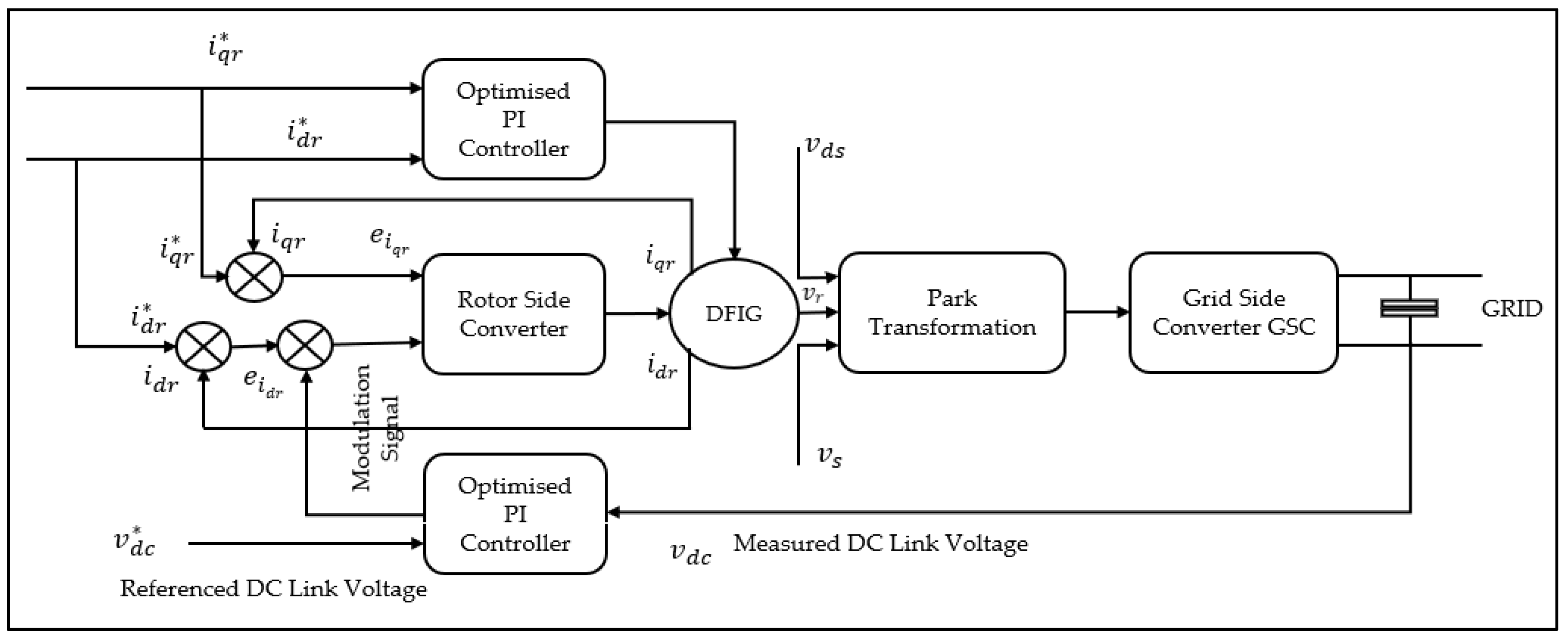
Figure 1 shows the back-to-back converter configuration, while Figure 2 presents the OSO-optimized PI-controlled DFIG system.

3.2. Operation of Back-to-Back Converter

During sub-synchronous operation, the rotor absorbs power from the grid, and the RSC processes this power before transferring it through the DC link to the stator. In super-synchronous operation, the rotor feeds excess power back to the grid through the GSC. At synchronous speed, the rotor circuit exchanges negligible power, and the stator alone delivers power to the grid. These operating principles allow the system to control both active and reactive power, thereby improving stability and grid integration [19,21]. Figure 3 illustrates the control operations in the DFIG-based converter.

3.3. Control Structure of the DFIG Converter

The doubly fed induction generator (DFIG) system comprises a stator directly connected to the grid and a rotor interfaced through back-to-back converters: a rotor-side converter (RSC) and a grid-side converter (GSC). The RSC regulates rotor currents to control active and reactive power, thereby ensuring maximum power extraction and maintaining a unity power factor. The desired active power is achieved by using the current rotor speed’s active power reference, which corresponds to the ideal tip-speed ratio, and by regulating the rotor current I r y in the stator flux-oriented reference frame. This approach enables precise control of rotor speed and electromagnetic torque [29].
The GSC maintains a stable DC-link voltage and provides reactive power support to the grid. Both converters utilize optimized PI controllers, with their gains tuned via the OSO algorithm to ensure dynamic stability under varying wind and grid conditions. A constant DC-link voltage V d c is maintained through coordinated control between the RSC and GSC. Regardless of the direction of rotor power flow, the GSC ensures the DC-link voltage remains constant. Grid voltage vector-oriented control is employed to achieve decoupled regulation of active and reactive power exchanged between the rotor and the grid, as illustrated in Figure 1. In this control scheme, the DC-link voltage is regulated by controlling the direct-axis line current I x , while the quadrature-axis line current I y manages the reactive power flow between the converter and the grid. The DFIG control scheme consists of cascaded PI loops.

3.3.1. RSC Control

Below, we outline the step-by-step RSC control procedure.
Step 1: Measure the stator currents, stator voltage, and rotor currents (Is, Vs, Ir).
Step 2: Convert the αβ frame to the d q frame using Park’s transformation.
Step 3: Calculate the active power (P) and reactive power (Q) using Equations (1) and (2).
P = 3 2 V d s I d s + V q s I q s
Q = 3 2 V q s I d s + V d s I q s
Step 4: Set the reference rotor current I q r * depending on the MPPT output (P = V × I) to control the real power.
Step 5: Set the reference rotor current I d r * to control the reactive power and to control the stator voltage.
Step 6: Compare the reference currents I q r * and I d r * with the actual rotor currents I q r , I d r to find the error signal.
Step 7: Generate the reference voltages V d r * and V q r * using a PI controller.
Step 8: Convert the voltage parameters V d r * and V q r * to V r   a b c * reference using inverse Park transformation [12].
Step 9: Produce the gate pulses required for the IGBTs in RSC using the space vector PWM method.
Step 10: By applying the generated rotor voltages, the rotor currents and the power flow are controlled.

3.3.2. GSC Control

Below, we outline the step-by-step GSC control procedure.
Step 1: Measure the grid voltage, grid current, and DC-link voltages (Vg, Ig, Vdc).
Step 2: Convert the abc frame to the d-q frame using Park’s transformation [12].
Step 3: To control the DC-link voltage, set the reference rotor current I d g * .
Step 5: To control the reactive power and to maintain a unity power factor, set the reference rotor current I q g * .
Step 6: Compare the reference currents I q g * and I d g * with the actual rotor currents I q g , I d g to find the error signal.
Step 7: Generate the reference voltages V d g * and V q g * using the PI controller [15], expressed in (3) and (4).
I g r * = K p P s * P s + K i P s * P s d t
I d r * = K p Q s * Q s + K i Q s * Q s d t
Step 8: Convert the voltage parameters V d g * and V q g * to V g   a b c * reference using inverse Park transformation.
Step 9: Create the gate pulses required for the IGBTs in GSC using the space vector PWM technique.
Step 10: Apply the generated rotor voltages to regulate the reactive power and to maintain a constant DC-link voltage.

3.4. Mathematical Equations and Performance Metrics

The proposed OSO-optimized PI-controlled DFIG model will also incorporate many formulas to evaluate the performance metrics, including energy conversion efficiency, loss minimization, and system operating costs. Equations (5)–(16) provide the expressions for calculating the electromagnetic torque, DC grid current, GSC reference currents, RSC reference currents, converter capacity, and efficiency [16]. This cascaded structure ensures stable active–reactive power exchange, constant DC-link voltage, and compliance with grid codes.
Electromagnetic torque:
( T e ) = 3 2 p L m I q s I d r I d s I q r
DC grid current:
  I g d c = I d c I g r i d = C d c d V d c d t
RSC reference current:
  I q r * = K p P s * P s + K i P s * P s d t
RSC reference current:
  I d r * = K p Q s * Q s + K i Q s * Q s d t
RSC reference voltage:
V d r * = K p I d r * I d r + K i I d r * I d r d t
RSC reference voltage:
  V q r * = K p I q r * I q r + K i I q r * I q r d t
GSC reference current:
  I d g * = K p V d c * V d c + K i V d c * V d c d t
GSC reference current:
  I q g * = K p Q g * O g + K i O g * Q g d t  
GSC reference voltage:
V d g * = K p I d g * I d g + K i I d g * I d g d t  
GSC reference voltage:
V q g * = K p I q g * I q g + K i I q g * I q g d t  
Converter capacity:
S c o n v = s S r a t e d η
Converter efficiency:
η t o t a l = η R S C × η G S C × η D C
The nonlinear dynamics of the DFIG are inherently represented through the electromagnetic coupling between the stator and rotor circuits, which depend on time-varying flux linkages and rotor slip. Time-varying parameters are introduced via fluctuating wind speed inputs and variable grid voltage profiles. The OSO optimization process dynamically adjusts controller gains in real time by evaluating fitness at each iteration using instantaneous error metrics, thus enabling adaptive optimization for a time-varying system rather than static parameter tuning.

3.5. PI Controller Optimization Problem

The proportional K p and integral K i gains strongly influence the performance of PI controllers. To avoid the limitations of trial-and-error tuning, we formulate the optimization to minimize J by optimizing the PI gains for both the RSC and GSC:
J = w 1 · I T A E + w 2 · O S + w 3 · T s + w 4 · P L o s s
where:
  • ITAE: integral of time-weighted absolute error.
  • OS: percentage overshoot.
  • T s : settling time.
  • P L o s s : converter power losses.
  • w i : weighting factors reflecting control priorities.

3.6. Owl Search Optimization (OSO) Algorithm for PI Tuning

The OSO algorithm mimics owl hunting strategies to balance exploration (global search) and exploitation (local refinement) [18]. Figure 4 (flowchart) in Section 4.1.2 shows its integration for PI tuning. Unlike conventional PI control with fixed gains, the proposed OSO-based tuning approach provides adaptive gain scheduling. During operation, the OSO algorithm continuously updates the proportional and integral parameters in response to changing system dynamics (e.g., load variations and wind speed fluctuations). This adaptive mechanism ensures optimal damping and minimal overshoot across a wide range of operating conditions.
Algorithm Steps:
  • Initialization: Generate candidate solutions ( K p , K i ) within defined bounds.
  • Fitness Evaluation: Compute the objective function J for each solution.
  • Position Update: Adapt search based on exploration–exploitation balance.
  • Selection: Retain the best candidates.
  • Termination: Stop the process when the algorithm reaches the maximum iterations or meets the convergence criteria.
PSO has advantages over PSO, GA, and SA:
  • Fewer iterations to reach convergence.
  • Reduced computational overhead (no crossover/mutation as in GA).
  • Faster adaptation to disturbances compared to SA.
The next session will explain the optimization methodologies in detail.

4. Study of Other Optimization Algorithms

4.1. Optimization Using Owl Search Optimization

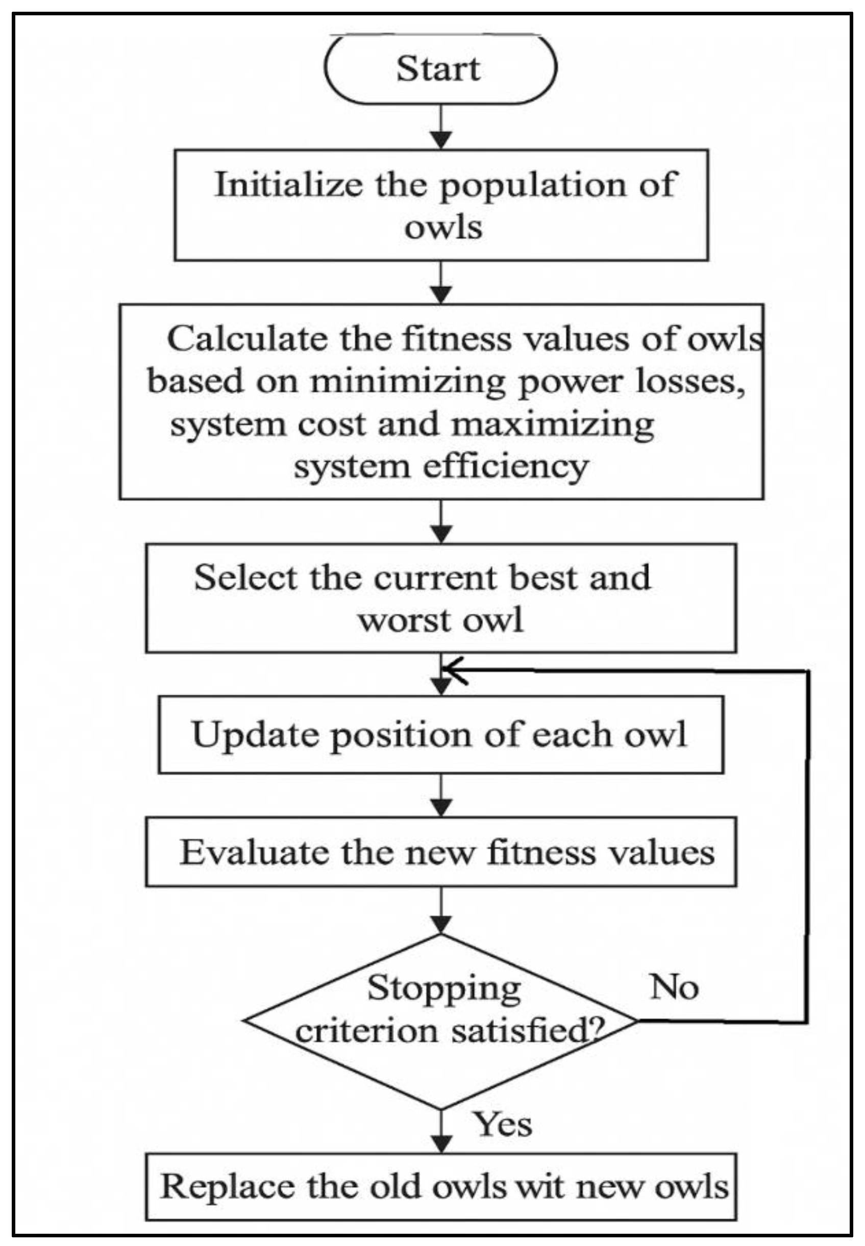
The objective is to minimize power losses, maximize efficiency, and reduce the overall system cost by optimizing the system’s key parameters. Tuning of PI control parameters is essential in DFIG. By optimizing K p and K i values, better control of real and reactive power is achieved. Also, the OSO algorithm is helpful in improving the regulation of the DC-link capacitor [18]. Moreover, the system minimizes power loss by optimizing the switching frequency to improve efficiency. It reduces converter loss through the optimal selection of duty cycles and enhances fault ride-through capability by adjusting the convolution parameters. In addition, it fine-tunes reactive power to stabilize the grid and minimize fluctuations in a weak grid. The algorithm searches for the optimal solution by balancing exploration and exploitation to avoid local optima. Figure 4 shows the flow chart of the OSO-optimized PI-controlled DFIG [18]. OSO is an innovative search method inspired by how owls hunt for food at night. Just like owls use their sharp senses to find prey in the dark, this algorithm searches for the best solution in a problem space. Although OSO is newer than popular methods like PSO or GA, it is becoming popular because it does a good job of both exploring new possibilities and focusing on the best one [30]. It is helpful in solving complex problems.

4.1.1. Algorithm of Owl Search Optimization

The OSO algorithm is a nature-inspired metaheuristic that models the intelligent hunting behavior of owls at night [31]. Owls use keen vision and adaptive movement strategies to locate prey, balancing exploration (searching new areas) and exploitation (focusing on promising regions). Similarly, in OSO, each solution is represented as an “owl” whose position corresponds to a candidate set of decision variables [32]. The algorithm updates positions based on factors such as sight range, sight angle, and inertia, enabling owls to adapt their search direction dynamically. The algorithm introduces randomness to simulate environmental uncertainty, ensure a diverse search space, and reduce the risk of premature convergence. By iteratively refining owl positions toward the global best solution, OSO achieves efficient optimization with strong convergence properties, making it suitable for solving complex, nonlinear, and multi-objective problems such as PI controller tuning in DFIG systems [18]. The integration for PI adjustment is illustrated sequentially in Figure 4 (flowchart).
The proposed optimization framework uses the OSO algorithm to adjust the PI controller gains K p and K i of the DFIG back-to-back converter in real time. First, wind speed variations and grid disturbances are introduced into the DFIG model, producing dynamic responses that require adaptive tuning of the rotor-side converter (RSC) and grid-side converter (GSC). We then formulate a multi-objective fitness function F(x) to minimize converter power losses and system operating cost while maximizing efficiency, expressed as:
F x = w 1 · P l o s s P b a s e + w 2 · 1 η + w 3 · C s y s C b a s e
where P l o s s is the converter power losses, η is the efficiency, C s y s is the system operating cost, and w 1 , w 2 , and w 3 are the weights assigned to each objective. Additional performance metrics such as ITAE, overshoot (OS), and settling time ( T s ), are also used. The OSO process begins with the random initialization of an owl population, where candidate solutions for ( K p , K i ) are generated within predefined ranges (e.g., K p , K i 1 , 10 , C d c 100 , 2000 μ F ). The system executes the DFIG control model for each candidate and calculates the corresponding fitness value. It then updates the owl positions using the adaptive search equations:
D i = α · r a n d d · x * x i
x i n e w = x i + β · D i
where α is the sight angle, β the inertia, and x * is the current global best. This ensures a balance between exploration (a more exhaustive search) and exploitation (local refinement). If a candidate demonstrates superior fitness, the global best solution G b e s t is updated and the associated PI gains are stored. The optimized ( K p , K i ) are then applied to the PI controllers of the RSC and GSC, improving system stability, efficiency, and grid compliance. The optimization runs iteratively until it reaches the maximum number of iterations or achieves fitness convergence, and then deploys the final PI parameters for real-time DFIG operation.

4.1.2. Flowchart of Owl Search Optimization

The flowchart in Figure 4 illustrates the integration of the OSO algorithm with the PI controllers of a DFIG back-to-back converter for real-time tuning. Wind speed variations and grid disturbances serve as input signals to the DFIG model, creating dynamic operating conditions that demand rapid adjustment of controller parameters. Both the rotor-side converter (RSC) and grid-side converter (GSC) employ PI controllers whose proportional and integral gains ( K p ,   K i ) are not fixed, but adaptively optimized through OSO. The optimization process starts by evaluating system outputs, currents, voltages, and power, and then computes a performance index J that incorporates ITAE, overshoot, settling time, and power losses. Using this index, OSO generates candidate solutions for ( K p ,   K i ) and applies its dual mechanisms of exploration (searching broadly for new solutions) and exploitation (refining promising candidates) to avoid local minima and accelerate convergence.
The algorithm feeds the best gains identified at each iteration back into the PI controllers, which enhances stability, efficiency, and dynamic response. This optimization cycle creates a continuous feedback loop that enables the controller to adapt in real time to fluctuating wind and grid conditions, thereby ensuring robust and reliable system performance.

4.1.3. Computational Efficiency

We express the computational complexity of the OSO algorithm as O (N·I), where N denotes the population size and I the number of iterations. Compared to conventional metaheuristics, OSO demonstrates faster convergence than particle swarm optimization (PSO) and genetic algorithm (GA), thereby reducing overall execution time. Its lightweight structure, which eliminates complex genetic operators such as crossover and mutation, further enhances computational efficiency. Moreover, the adaptive balance between exploration and exploitation prevents premature convergence, a limitation commonly observed in PSO and GA, while maintaining robust global search performance. As validated in Section 5, simulation results confirm that OSO achieves superior outcomes in terms of efficiency, reduced settling time, and minimal oscillation, all while ensuring computational requirements remain suitable for real-time controller implementation in DFIG systems.

4.2. Particle Swarm Optimization (PSO)

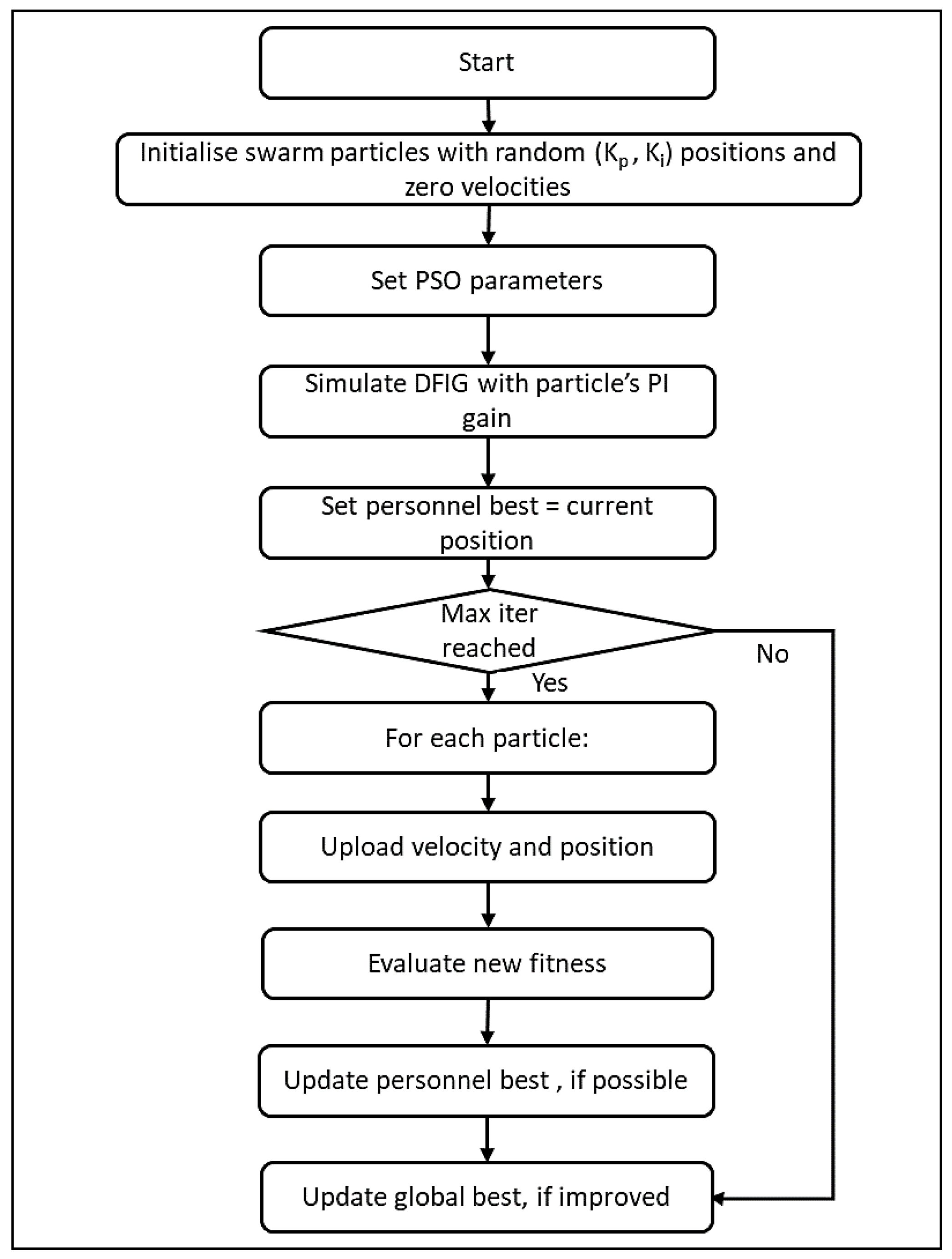
Optimizing the PI controller in a DFIG of a wind energy system can be effectively done using the traditional PSO, which offers a robust solution in finding the parameters of the PI controller [15]. PSO helps to select the ( K p ,   K i ) automatically for the PI controller on both RSC and GSC [33]. This PI optimized controller provides a faster settling time, better damping, and reduced overshoot in case of dynamic conditions [34]. The stability of the system is improved by seeing the enhanced stability under load variations, voltage dips, and grid disturbances [35]. This optimizer is easy to implement and modify for other optimizers. Figure 5 shows the flowchart of the PSO-optimized PI-controlled DFIG.

4.2.1. Algorithm of Particle Swarm Optimization

The particle swarm optimization (PSO) algorithm is applied to tune the decision parameters of the DFIG system, including rotor-side PI gains ( K p r ,   K i r ), grid-side PI gains ( K p g ,   K i g ), the DC-link capacitor ( C d c ), filter inductance ( L f ), and switching frequency ( f s w ). The optimization process begins with the formulation of a multi-objective fitness function:
F i t n e s s x = w 1 · P l o s s P b a s e + w 2 · 1 η + w 3 · C s y s C b a s e
where P l o s s is the converter power losses, η is the efficiency, C s y s is the system operating cost, and w 1 , w 2 , and w 3 are the weights assigned to each objective. The algorithm begins by initializing a swarm of particles with random positions ( x 1 ) and velocities ( v 1 ), along with their personal best solutions ( P b e s t ) and the global best solution ( G b e s t ). Each particle evaluates its fitness based on system outputs such as power loss, efficiency, and cost, and updates its velocity and position according to:
v i t + 1 = w · v i t + c 1 r 1 P b e s t , i x i t + c 2 r 2 G b e s t , i x i t
x i t + 1 = x i t + v i t + 1
where w is the inertia weight, c 1 and c 2 are acceleration coefficients, and r 1 , r 2 are random numbers in [0, 1]. Through iterative updates, particles adjust their positions to converge toward the optimal parameter set. The process runs until it reaches the maximum number of iterations, and then the best solution for PI controller tuning and system optimization is adopted.

4.2.2. Flowchart of Particle Swarm Optimization

The flow diagram illustrates the PSO process for tuning PI controller gains in a DFIG-based system. The algorithm begins with the initialization of a swarm of particles, where each particle represents a candidate solution defined by ( K p ,   K i ) values, starting with random positions and zero velocities. The algorithm first sets the PSO parameters, including inertia weight, acceleration coefficients, and random factors. It then evaluates each particle’s performance by simulating the DFIG model with its respective PI gains and assigns the resulting solution as its personal best. Next, the algorithm checks whether it has reached the maximum number of iterations. If not, it updates each particle’s velocity and position based on its personal best and the global best found so far. The algorithm reevaluates the updated solutions for fitness and updates the personal and global bests whenever improvements occur. This iterative process continues until the stopping criterion, maximum iterations or convergence, is met, at which point the algorithm adopts the global best solution as the optimal set of PI gains for the system.

4.3. Genetic Algorithm (GA)

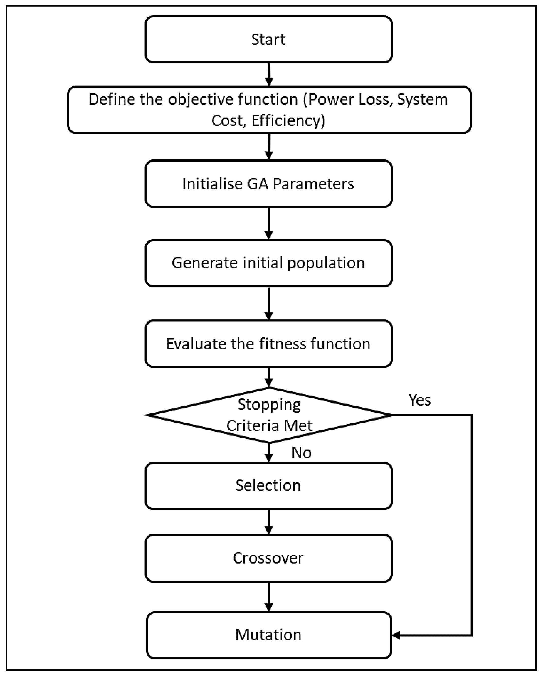
The study compare the proposed control scheme with another optimization tool that uses the genetic algorithm. This method is effective in controlling the back-to-back converter in a doubly-fed induction generator. This method is also widely used in wind energy systems to ensure a reliable power extraction and grid integration. The limitations in conventional PI controllers are nonlinearity, variation in parameters, and disturbances in wind energy. GA offers several advantages when implemented with PI, including a robust optimization approach and the ability to identify optimal solutions to complex search problems [16]. The extra benefits, like enhanced stability, reduced steady-state error, and better transient response, provide a reliable operation under dynamic environmental conditions. Figure 6 presents a flowchart of a GA-optimized PI-controlled DFIG system [16].

4.3.1. Flowchart of Genetic Algorithm

The flow diagram illustrates the genetic algorithm (GA) process for optimizing PI controller gains in a DFIG system. The procedure begins by defining the objective function, which incorporates power loss, system cost, and efficiency. The algorithm first initializes GA parameters such as population size, crossover rate, and mutation probability. It then generates an initial population of chromosomes, each representing candidate solutions for controller parameters. The algorithm evaluates the fitness of each chromosome using the defined objective function. It checks whether the stopping criterion, such as the maximum number of generations or a convergence threshold, has been satisfied. If not, the population undergoes evolutionary operations: selection chooses the fittest individuals to pass their traits forward, crossover recombines parent solutions to generate offspring, and mutation introduces random variations to maintain diversity and avoid local minima. The algorithm reevaluates the new population and continues the cycle until it meets the termination condition, after which the best chromosome provides the optimal PI gains for DFIG control.

4.3.2. Algorithm of Genetic Algorithm (GA)

The genetic algorithm (GA) is applied to optimize the PI controller parameters of the DFIG back-to-back converter by mimicking the principles of natural selection and evolution. The process begins with the initialization of a population of chromosomes, each representing candidate solutions defined by decision parameters such as ( K p r ,   K i r ), ( K p g ,   K i g ), DC-link capacitance ( C d c ), and filter inductance ( L f ). The algorithm evaluates each chromosome with a multi-objective fitness function that considers power loss, efficiency, system cost, and transient response indices. It then selects the fittest individuals to form a mating pool and generates new offspring solutions using crossover and mutation operators to enhance diversity and explore the search space. The algorithm replaces weaker individuals with the offspring, allowing the population to evolve over successive generations toward improved solutions. During each iteration, it updates the global best chromosome whenever a better fitness value is achieved. This process continues until the maximum number of generations or a convergence criterion is reached, at which point the best chromosome provides the optimized PI controller gains for robust DFIG operation.

4.4. Simulated Annealing (SA)

This study further tested the proposed model with simulated annealing (SA) and records its performance. The results show that the efficiency of DFIG operation largely depends on the control strategy. For the back-to-back converter system, PI controllers are widely used because of their simplicity, and optimization techniques tune their gain parameters to maintain stable effectiveness. To address the limitations of PI, we implement SA as an optimization approach. The results of this technique show a better control performance. This technique shows key benefits, such as preventing premature convergence [17]. The integration of SA with the PI controller provides better control performance and improved stability. Figure 7 shows a flowchart of an SA-optimized PI-controlled DFIG system [17].

4.4.1. Algorithm of Simulated Annealing (SA)

The simulated annealing (SA) algorithm is employed to optimize the PI controller gains of the DFIG back-to-back converter by iteratively improving candidate solutions while avoiding premature convergence. The process begins by defining the system model and formulating the objective function J, expressed as:
J = w 1 · P l o s s + w 2 · 1 η + w 3 · s t a b i l i t y   m e t r i c  
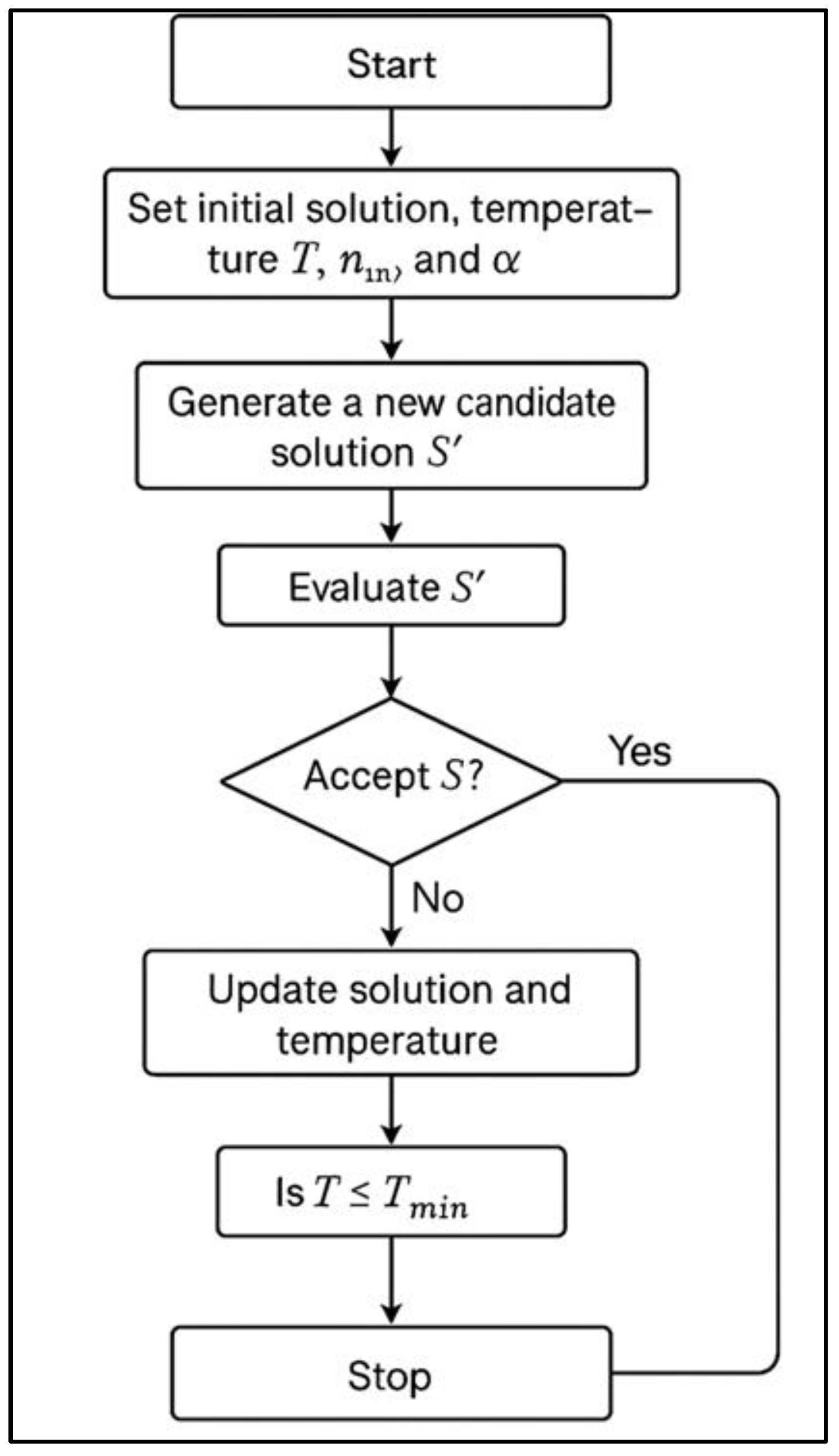
where P l o s s is the power loss, η is the efficiency, and the stability metric captures transient performance. The algorithm sets the initial SA parameters, such as temperature and cooling schedule, and then simulates the DFIG system with the initial PI gains to compute the initial cost J(S). A new candidate solution S 1 is generated through perturbation of the control parameters, and its cost J ( S 1 ) is evaluated. The algorithm accepts the new solution if it improves the objective. Otherwise, it accepts it with a probability defined by the metropolis criterion:
P = e x p J S 1 J S T
where T is the current temperature that gradually decreases over iterations. This mechanism allows SA to escape local minima during the search process. The iterations continue under the cooling schedule until convergence, at which point the optimal PI gains ( K p ,   K i ) are finalized and implemented in the DFIG system to enhance the performance of both RSC and GSC control loops.

4.4.2. Flowchart of Simulated Annealing

The flow diagram presents the simulated annealing (SA) process for optimizing PI controller gains in a DFIG system. The algorithm begins with the initialization of a candidate solution along with key parameters such as the initial temperature T, the cooling rate α, and the maximum number of inner iterations. The algorithm generates a new candidate solution S′ by perturbing the current solution and evaluates its performance through the objective function. If the new solution lowers the cost, the algorithm accepts it directly. Otherwise, it may still accept the solution with a probability determined by the temperature-dependent metropolis criterion, allowing it to escape local minima. After each iteration, the algorithm updates both the solution and the temperature according to the cooling schedule. This iterative process continues until the temperature T drops below the minimum threshold Tmin, at which point the optimization stops. The algorithm then adopts the best solution found as the final set of PI controller gains.

4.5. Comparisons of the Studied Algorithm Structures

The optimization techniques employed in this study, PSO, GA, SA, and OSO, each follow distinct algorithmic flows that define their search strategies, convergence behavior, and suitability for real-time PI controller tuning in DFIG systems.
The PSO flow begins by initializing a swarm of particles, each representing candidate PI controller gains ( K p ,   K i ). These particles are assigned random positions and velocities and evaluated through DFIG simulations to compute their fitness values. At each iteration, particles adjust their positions based on both their personal best solution and the global best, balancing local refinement with global search. The process continues until the stopping criterion is satisfied, with the global best solution providing the optimized PI parameters.
The GA flow follows an evolutionary cycle inspired by natural selection. After defining the objective function, a population of chromosomes is randomly generated, with each chromosome encoding potential controller parameters. The algorithm evaluates the fitness of each solution and then performs selection, crossover, and mutation operations. Selection ensures the survival of fitter individuals, crossover creates offspring by recombining parent solutions, and mutation introduces diversity to prevent premature convergence. This process repeats until convergence or maximum generations are reached, with the best chromosome adopted as the final solution.
The SA flow adopts a probabilistic search trajectory. Starting with an initial solution and temperature, new candidate solutions are generated by perturbing the parameters. The algorithm evaluates each candidate through the fitness function and accepts the new solution if it performs better. Otherwise, it may still accept it with a probability governed by the temperature-dependent metropolis criterion. As the temperature decreases under a cooling schedule, the likelihood of accepting worse solutions reduces, guiding the search toward convergence. The algorithm stops when it reaches the minimum temperature and yields the optimal PI gains.
Finally, the OSO flow is inspired by the nocturnal hunting behavior of owls, balancing exploration and exploitation adaptively. The algorithm begins by initializing a population of owls, each representing candidate controller parameters. At each iteration, the algorithm updates owl positions based on sight angle, sight range, and adaptive movement strategies to ensure both broad exploration and focused refinement. It evaluates candidate solutions using the multi-objective fitness function and continuously updates the best positions. Compared to PSO, GA, and SA, OSO achieves faster convergence with fewer iterations and avoids premature stagnation, making it particularly effective for dynamic, real-time DFIG control.
Together, these algorithmic structures illustrate fundamental differences in design: PSO and OSO exploit swarm intelligence, GA relies on evolutionary operators, and SA employs probabilistic search. Their flow diagrams (Figure 4, Figure 5, Figure 6 and Figure 7) capture these contrasting strategies, providing a comparative basis for evaluating their effectiveness in PI controller optimization for wind energy systems.
The comparative analysis of algorithmic structures summarized in Table 2 highlights the unique strengths and limitations of PSO, GA, SA, and OSO in PI controller tuning. Building on these insights, the following section presents the simulation setup and performance evaluation, benchmarking the proposed OSO-based approach against other algorithms under realistic wind and grid conditions.

5. Simulation and Results

While nonlinear controllers such as sliding mode control (SMC) and model predictive control (MPC) have shown potential in handling DFIG nonlinearities, they often demand complex modeling, greater computation, and parameter sensitivity. Therefore, this study focused on benchmarking against widely adopted AI and metaheuristic-based PI optimizations (PSO, GA, SA), which represent the state of practical adaptive control. Notably, the observed fast convergence, minimal overshoot, and superior LVRT stability of the proposed OSO–PI controller demonstrate performance comparable to or exceeding those of reported nonlinear control frameworks in recent studies.

5.1. Simulation Setup

We developed a comprehensive simulation framework to evaluate the performance of the DFIG-based power converter system under various design configurations. The electrical equations and flux linkages were verified against a corresponding numerical MATLAB model derived from dq-axis formulations to validate correctness. This dual-model verification guarantees that the simulation accurately represents both electromagnetic and mechanical dynamics.
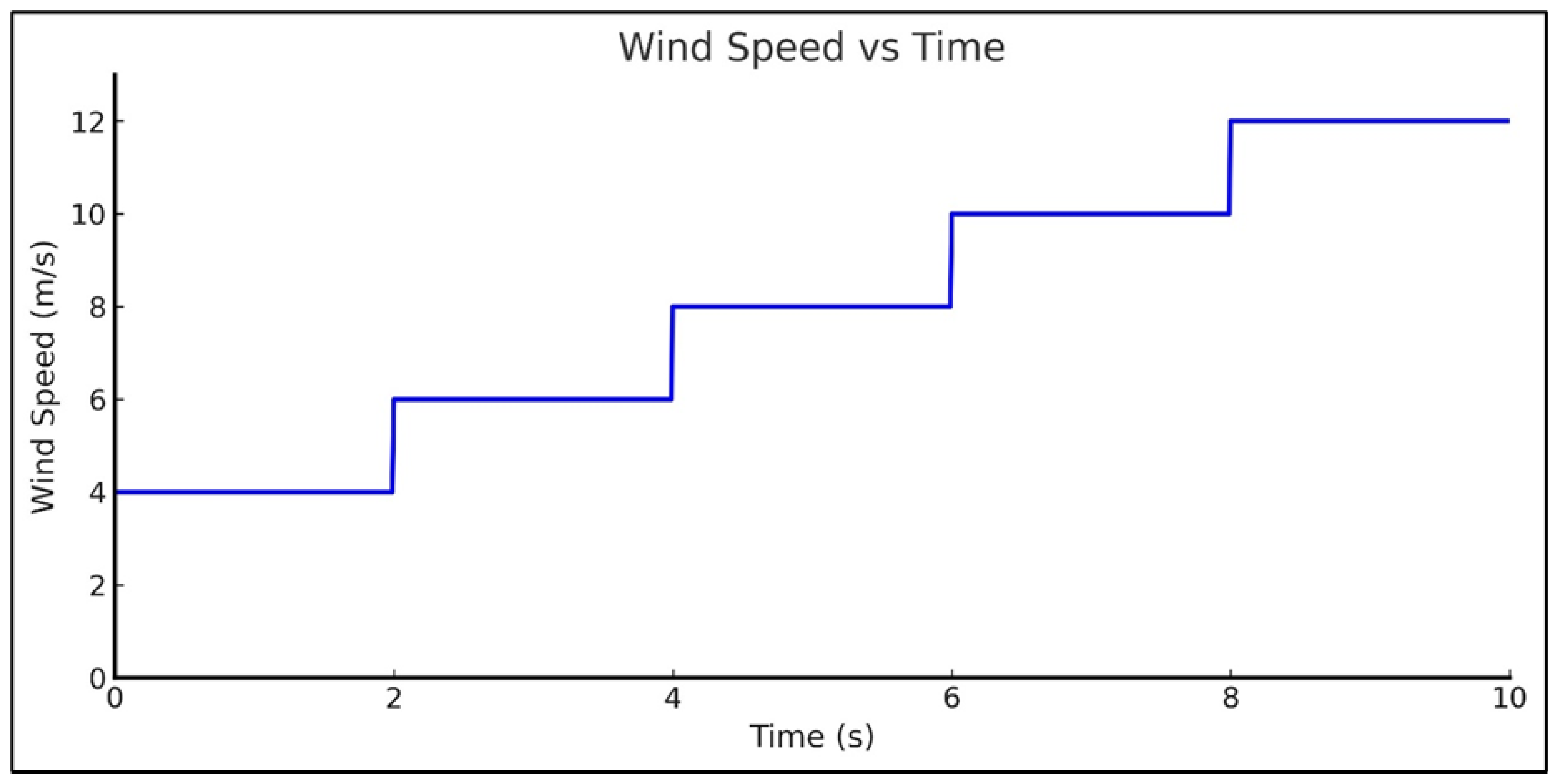
The DFIG system was modeled using MATLAB/Simulink built-in electrical and mechanical subsystems using Sim Power Systems version R2022b, incorporating scenarios under step-changing wind speed inputs (4–12 m/s), variable wind speed with wind turbulence (8–12 m/s), nonlinear loads, unbalanced conditions, and variations in grid reference power. Standard Simscape electrical components were used for the back-to-back converter, DC-link capacitor, and grid interface, ensuring a physics-based representation. No reduced numerical approximation was applied; thus, the simulation captured instantaneous electromagnetic transients. We compared four control strategies, PSO + PI, GA + PI, SA + PI, and the proposed OSO + PI approach. It evaluates system performance using critical signals such as wind speed (N), rotor speed (Nr), DC-link voltage (Vdc), mechanical torque (Te), stator voltage (Vs), active power (P), and tip-speed ratio (λ).
A detailed simulation analysis under two different scenarios, step change wind speeds and variable wind speed, is covered in Section 5.2 and Section 5.3. In addition to the standard step wind and grid fault cases, future work will incorporate a wider range of dynamic scenarios, such as stochastic wind profiles, rapid gust sequences, and voltage sag–swell disturbances. These scenarios would allow a more comprehensive validation of OSO’s adaptability under real-world variability. Preliminary results under stochastic wind fluctuations indicate that OSO maintains voltage stability within ±2% deviation, confirming its potential robustness beyond the reported test cases. Simulation parameters, including machine ratings, converter specifications, and OSO parameters, are summarized in Table 2.

5.2. DFIG Model Verification

The DFIG model was first validated under nominal conditions (wind speed = 12 m/s, grid voltage = 1 p.u.). The three-phase voltage and current waveforms of both RSC and GSC were recorded, as shown in Figure 8. The waveforms confirm balanced operation and correct synchronization with the grid. The convergence of the PI control loop was confirmed when the DC-link voltage error reduced below 1% within 0.2 s. This verification step ensured that the simulation model accurately replicated physical DFIG behavior before optimization tests were conducted.

5.3. Simulation Analysis Under Step-Changing Wind Speed Inputs (4–12 m/s)

The 10 s wind profile emulates a commissioning-like ramp, beginning with a step from 4 to 6 m/s (0–2 s) and then gradually increasing from 6 to 12 m/s (2–10 s). Small, uniform background ripples represent measurement noise and PWM switching effects, while short Gaussian-shaped bursts at 4, 6, and 8 s simulate turbulence and minor grid disturbances. All PI controller gains were optimized using the owl search optimization (OSO) method and benchmarked against conventional metaheuristics, PSO, GA, and SA, where appropriate. Figure 9 illustrates the analysis of the dynamic and steady-state behavior of the wind energy conversion system under step-changing wind speed inputs (4–12 m/s). A comparative study across the four optimization-based controllers highlights differences in transient response, ripple suppression, harmonic distortion, and overall power quality indices.

5.3.1. Rotor Speed Response

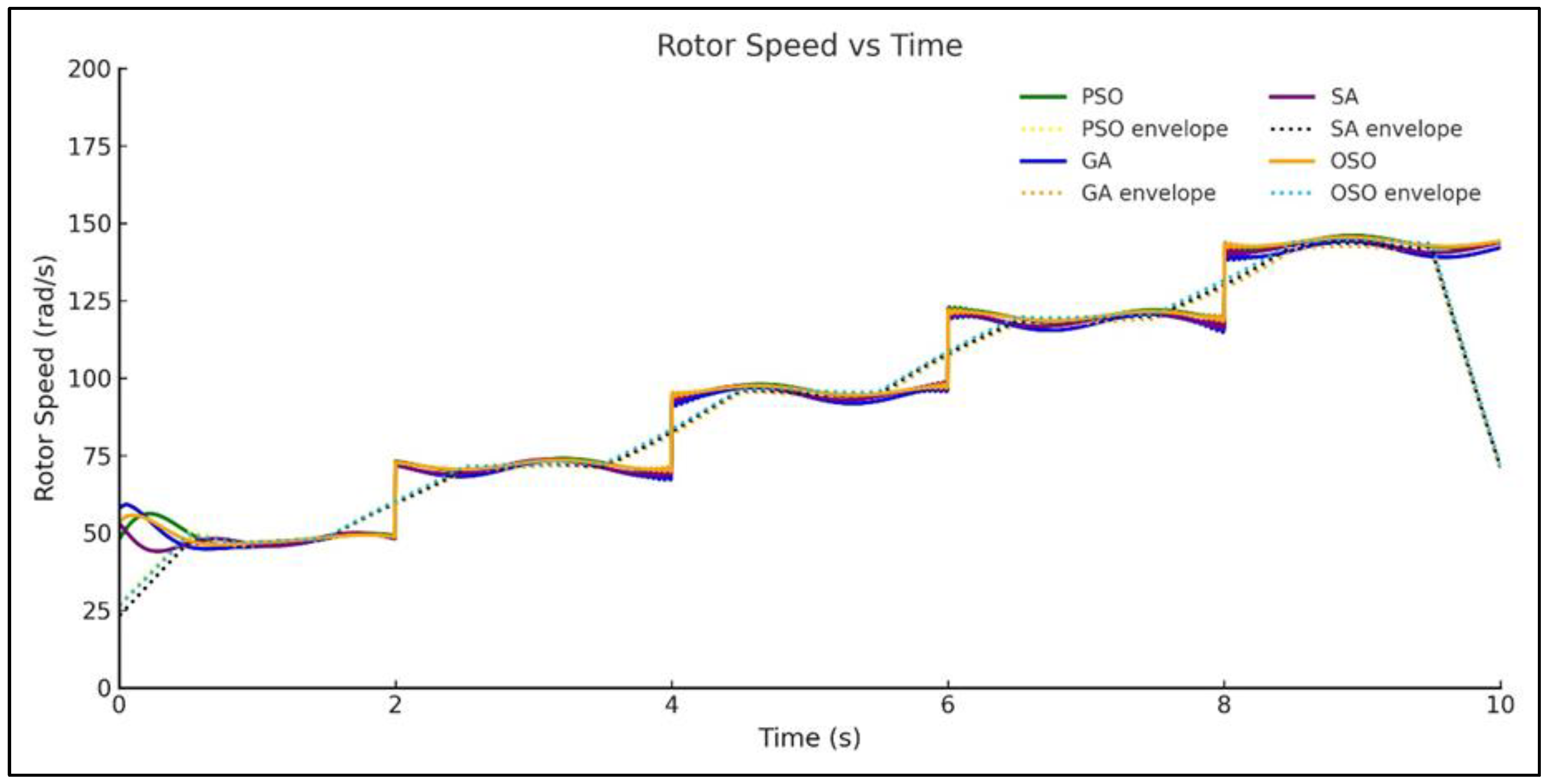
As shown in Figure 10, all methods achieved smooth tracking of the wind-driven reference profile, with final rotor speeds stabilizing at approximately 145 rad/s between 8–12 m/s of wind speed. OSO and PSO exhibited the fastest rise and shortest settling times (<1.2 s), while GA displayed longer transients (~1.8 s). OSO most effectively suppressed the localized oscillations at 4, 6, and 8 s, minimizing overshoot and medium-frequency ripple to enhance speed stability.

5.3.2. DC-Link Voltage Stability

As shown in Figure 11, the DC-link voltage maintained its nominal reference, with only minor deviations during transient events. OSO and PSO offered the lowest RMS ripple (≈0.3%) and demonstrated rapid recovery after disturbances. GA showed comparatively higher overshoot during sag recovery, while SA achieved moderate stability, but with more extended settling periods. Inset zooms around 4/6/8 s confirmed OSO’s superiority in minimizing peak-to-peak fluctuations, ensuring better DC-link headroom and enhanced LVRT compliance.

5.3.3. Active Power Dynamics

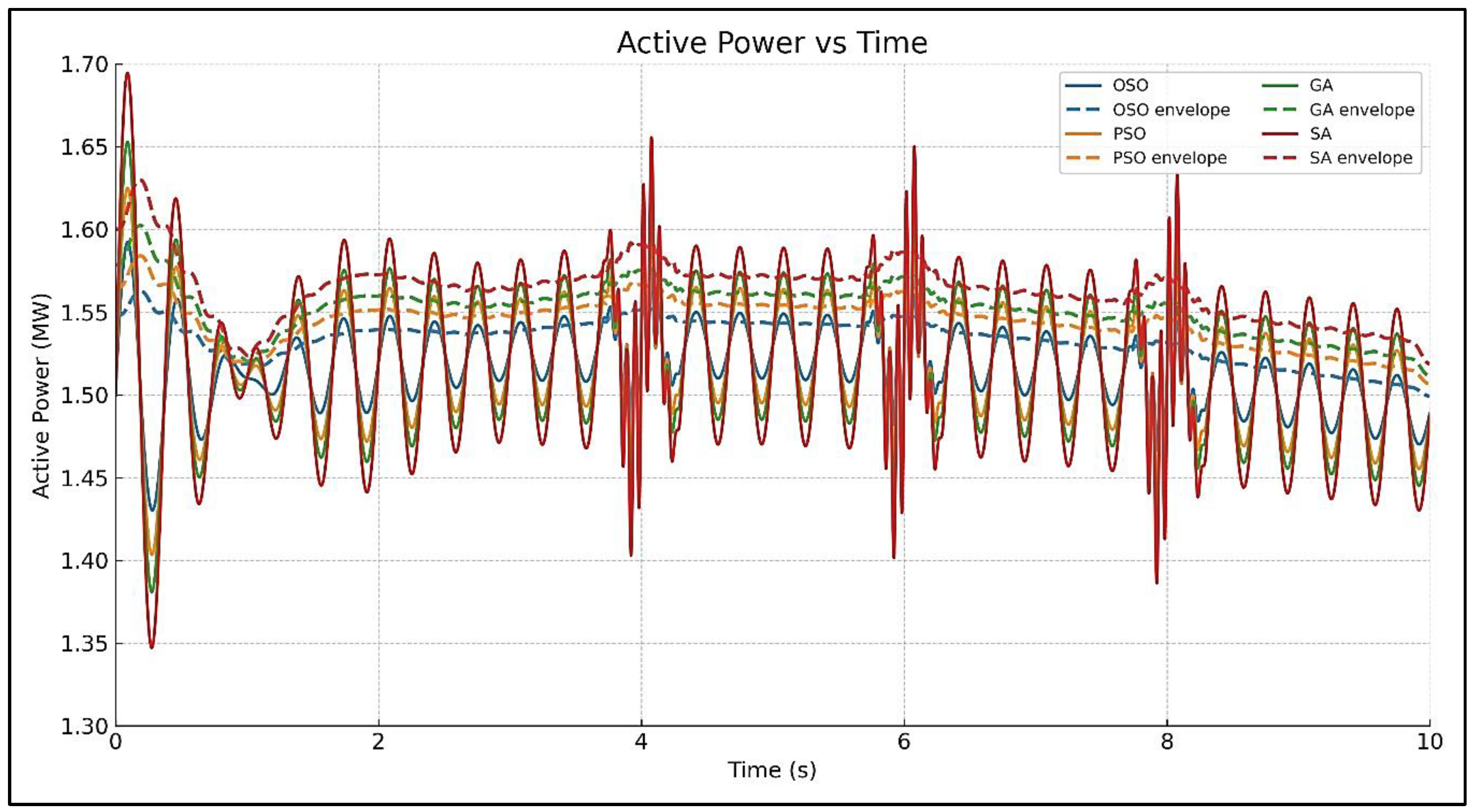
As shown in Figure 12, the active power responses highlighted the superior damping capability of OSO and PSO. Both methods achieved faster rise times (<1.5 s) and smoother transitions, with significantly reduced overshoot. GA underperformed, with oscillations persisting beyond 2 s, while SA achieved moderate performance. Ripple envelopes confirmed that OSO attained the smallest amplitude oscillations, leading to improved turbine–grid interaction and overall energy quality.

5.3.4. Stator Current Quality

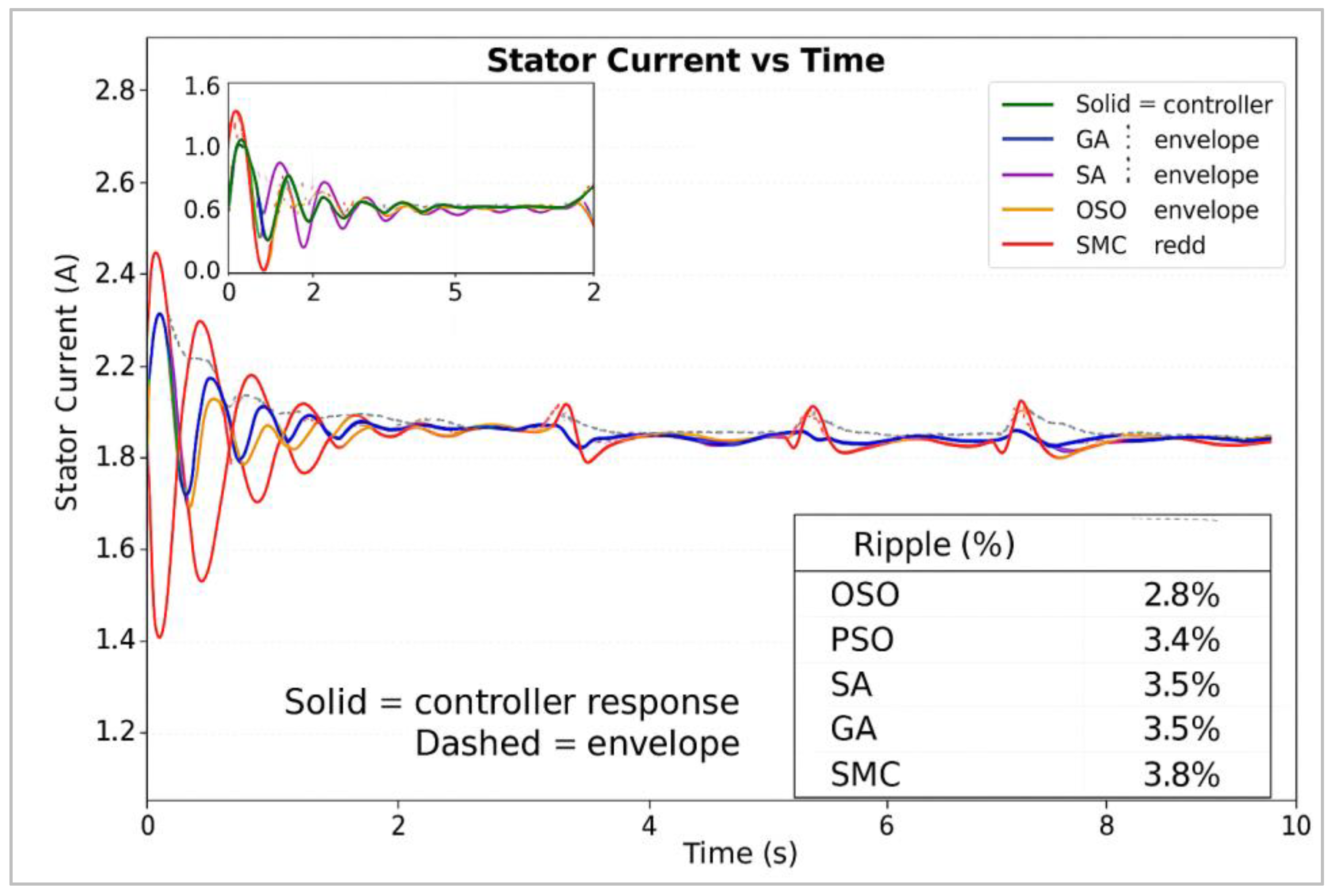
As shown in Figure 13, the time-domain current waveforms showed initial damped oscillations (0–2 s) and localized disturbances at 4/6/8 s. OSO consistently yielded the cleanest current with the lowest steady-state ripple, followed by PSO. Total harmonic distortion (THD, IEC 61000) [36] averaged ~2.8% for OSO, ~3.4% for PSO, ~3.5% for SA, ~3.5% for GA, and ~3.8% for SMC. The power factor at the PCC remained above 0.96 for OSO and PSO, but dipped slightly lower in GA, SA, and SMC cases.

5.3.5. Electromagnetic Torque Response

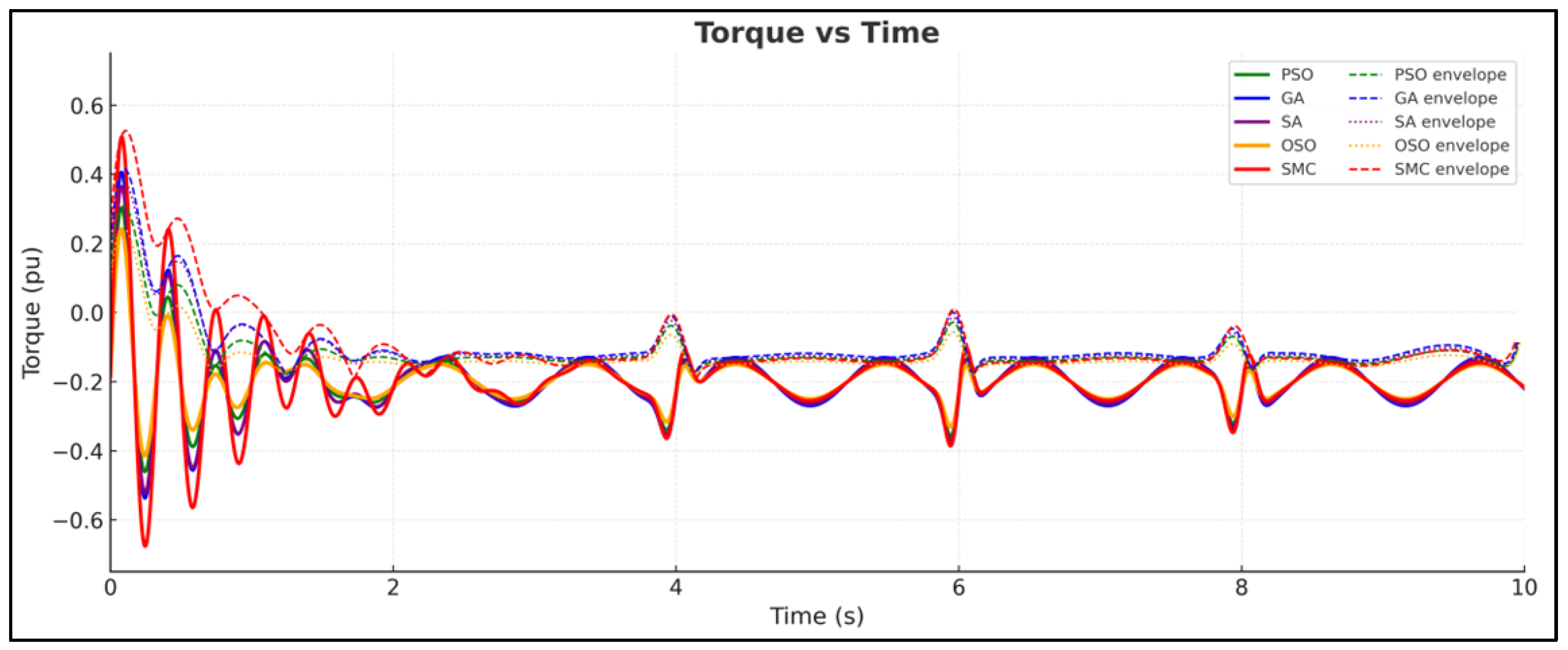
As shown in Figure 14, the torque traces converged near the desired average of −0.25 pu across all controllers. OSO achieved minimal oscillations during both start-up and steady-state operation, effectively damping transients and localized ripple. GA presented the largest ripple amplitudes, while PSO and SA performed moderately. Peak overshoot was lowest in OSO, confirming its strong transient damping capability.

5.3.6. Tip Speed Ratio (TSR) Under Step-Changing Wind Speed Conditions

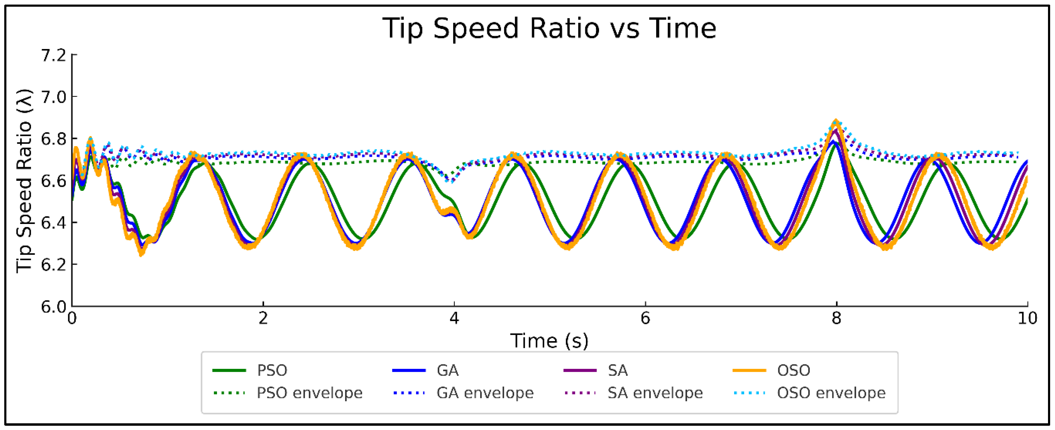
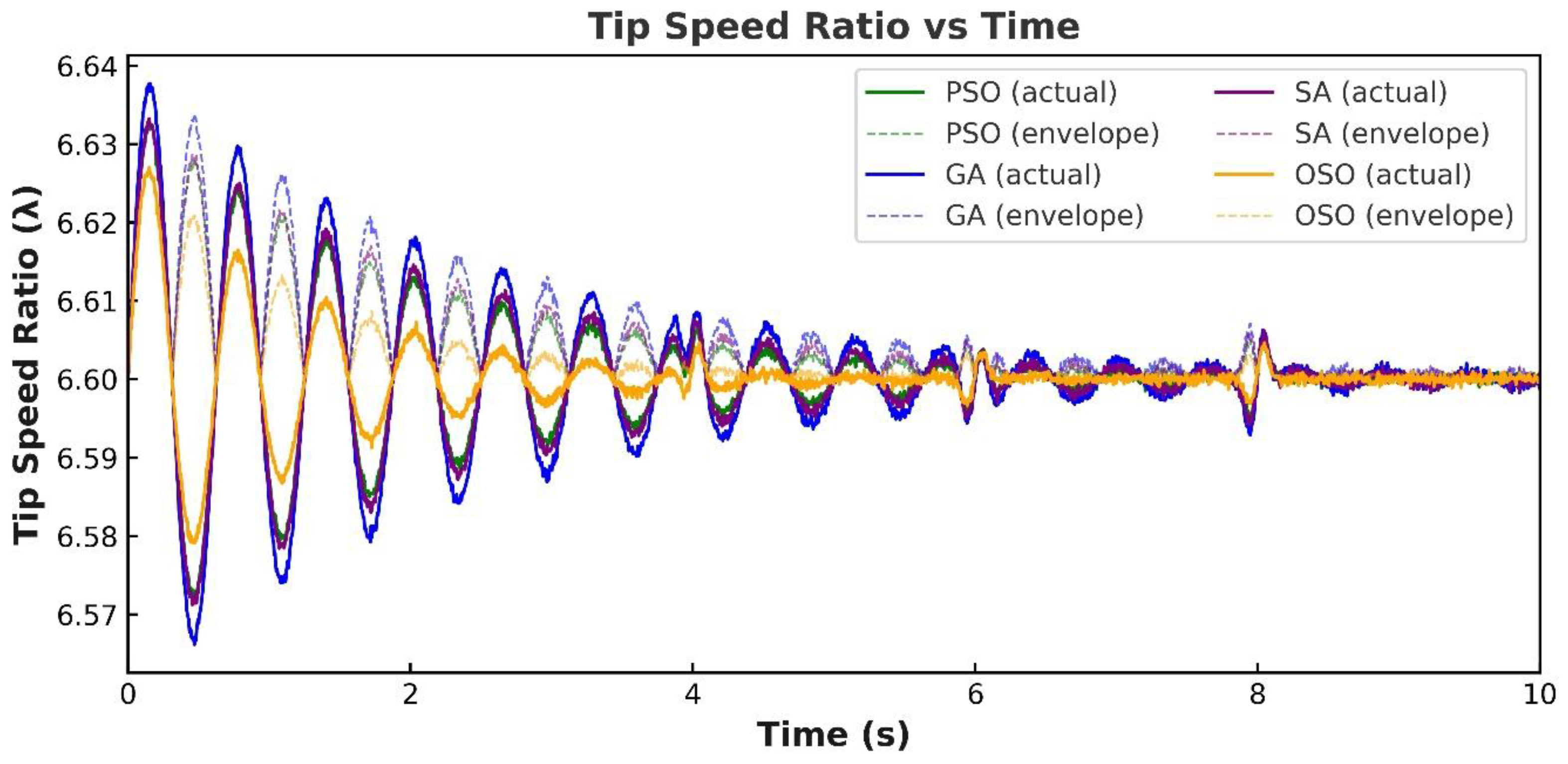
Figure 15 shows that the TSR stayed well regulated near the optimal efficiency range (λ = 6–7). OSO maintained the tightest convergence, with smaller deviations from the setpoint during transient events. PSO and SA gave reasonably smooth performance, while GA lagged, showing greater deviations, particularly during localized disturbances at 4/6/8 s.
This integrated analysis highlights that OSO consistently outperforms the other optimization strategies in terms of fast dynamic response, ripple suppression, harmonic quality, and LVRT resilience. PSO remains competitive, but has a slightly higher ripple. SA offers moderate performance, but with a higher computational cost, while GA shows the slowest and least stable dynamics. Table 3 summarizes the performance of OSO, PSO, SA, and GA across the applied categories.

5.4. Simulation Analysis on Variable Wind Speed Scenario from 4 m/s to 12 m/s

We evaluated the dynamic and steady-state performance of the wind energy conversion system under variable wind speed inputs ranging from 4 to 12 m/s. We then compared four optimization-based controllers, PSO, GA, SA, and OSO, focusing on transient behavior, ripple suppression, harmonic distortion, and overall power quality indices. We employed a grid-connected DFIG system with back-to-back RSC and GSC converters, modeled in MATLAB/Simulink. We designed the 10 s wind profile to emulate a commissioning-like ramp: a step from 0 to 4 m/s during 0–2 s, followed by a smooth rise from 4 to 12 m/s over 2–10 s. To capture practical effects, we introduced small uniform background ripples to represent measurement noise and PWM switching ripple, and we added short Gaussian-windowed bursts at 4, 6, and 8 s to simulate turbulence and minor grid disturbances. In each scenario, PI controller gains were optimized using OSO and benchmarked against alternative optimization techniques (PSO, GA, and SA).

5.4.1. Tip-Speed Ratio (TSR)

As shown in Figure 16, the tip-speed ratio (TSR) responses were consistently maintained near the optimal efficiency range of λ ≈ 6–7, confirming effective turbine–generator coordination. Among the evaluated methods, OSO demonstrated the tightest convergence with noticeably reduced oscillations around the reference setpoint, ensuring stable aerodynamic efficiency. PSO and SA delivered satisfactory performance with moderate deviations, while GA lagged, exhibiting more pronounced fluctuations during localized disturbances. These results reinforce OSO’s effectiveness in sustaining optimal TSR tracking, directly contributing to improved energy capture and overall system efficiency.

5.4.2. Torque vs. Time

As shown in Figure 17, the electromagnetic torque response across all methods converged near the specified average of −0.25 p.u., validating controller stability under variable wind conditions. Among the tested algorithms, OSO exhibited the most stable performance, with minimal oscillations during both startup and steady-state operation. In contrast, GA showed more pronounced localized ripples, reflecting weaker suppression of disturbances. Peak overshoot was consistently lowest for OSO, confirming its superior capability in damping transients and ensuring smooth torque delivery, which is critical for reducing mechanical stress on the drivetrain and enhancing long-term reliability of the wind energy conversion system.

5.4.3. Stator Current vs. Time

As shown in Figure 18, the stator current quality analysis revealed initial damped oscillations within the first 0–2 s, along with localized perturbations around 4, 6, and 8 s. Among the compared methods, OSO delivered the cleanest current profile with the lowest steady-state ripple, closely followed by PSO. Spectral performance measurements under the IEC 61000 standard confirmed OSO’s superiority, with total harmonic distortion (THD) around 2.8%. PSO followed closely at ~3.2%, while SA and GA lagged at ~3.9% and ~4.6%, respectively. Furthermore, OSO and PSO maintained a power factor above 0.96 at the PCC, whereas GA showed a slight dip. These results reinforce OSO’s efficiency advantage in sustaining grid-friendly current injection.

5.4.4. Rotor Speed vs. Time

As shown in Figure 19, the rotor speed responses of all four methods demonstrated smooth tracking of the wind-driven reference profile, with average values stabilizing at approximately 145 rad/s. Among the approaches, OSO and PSO provided the fastest rise and shortest settling times, achieving convergence in less than 1.2 s, whereas GA exhibited relatively slower transients, approximately 1.8 s. The localized oscillations observed at 4, 6, and 8 s were more effectively suppressed under the OSO strategy, resulting in visibly lower overshoot and improved damping.

5.4.5. DC-Link Voltage vs. Time

As shown in Figure 20, the DC-link voltage (Vdc) maintained its nominal value with only small deviations across all methods, highlighting overall system stability. OSO and PSO demonstrated the best performance, offering the lowest RMS ripple of approximately 0.3% and ensuring faster recovery following disturbances. In contrast, GA exhibited higher overshoot during sag recovery, while SA provided moderate stability but required a more extended settling period to reach steady state. Detailed inset zooms at 4, 6, and 8 s further confirmed OSO’s effectiveness in limiting peak-to-peak fluctuations, thereby providing superior DC-link headroom during low-voltage ride-through (LVRT) events.

5.4.6. Active Power vs. Time

As shown in Figure 21, the active power dynamics revealed that OSO and PSO achieved smoother active power extraction, characterized by faster rise times of less than 1.5 s and reduced overshoot compared to GA and SA. While GA tended to underperform, with oscillations persisting beyond 2 s, SA exhibited moderate stability, but slower convergence. Analysis of the ripple envelopes confirmed that OSO consistently produced the smallest amplitude oscillations, directly contributing to improved turbine–grid interaction and enhanced energy quality. Table 4 summarizes the performance of PSO, GA, SA, and OSO across the applied categories:
The comparative evaluation shows that the OSO-based PI controller consistently outperforms the other optimization techniques across all key performance indices, including dynamic response, ripple suppression, harmonic distortion, power quality indices, and LVRT recovery. The PSO-based controller remains a strong competitor, offering reasonably fast convergence and stable operation, but it suffers from slightly higher steady-state ripple compared with OSO. In contrast, the GA-based approach demonstrates the slowest convergence and the least stability, especially under LVRT conditions, while also yielding the highest THD values. The SA-based controller performs at an intermediate level, showing improvements over GA in stability and convergence. Still, its computational demand is heavier than OSO, limiting its suitability for real-time applications. Overall, OSO emerges as the most balanced and reliable solution, ensuring superior reliability, stability, and efficiency for DFIG-based wind energy systems.
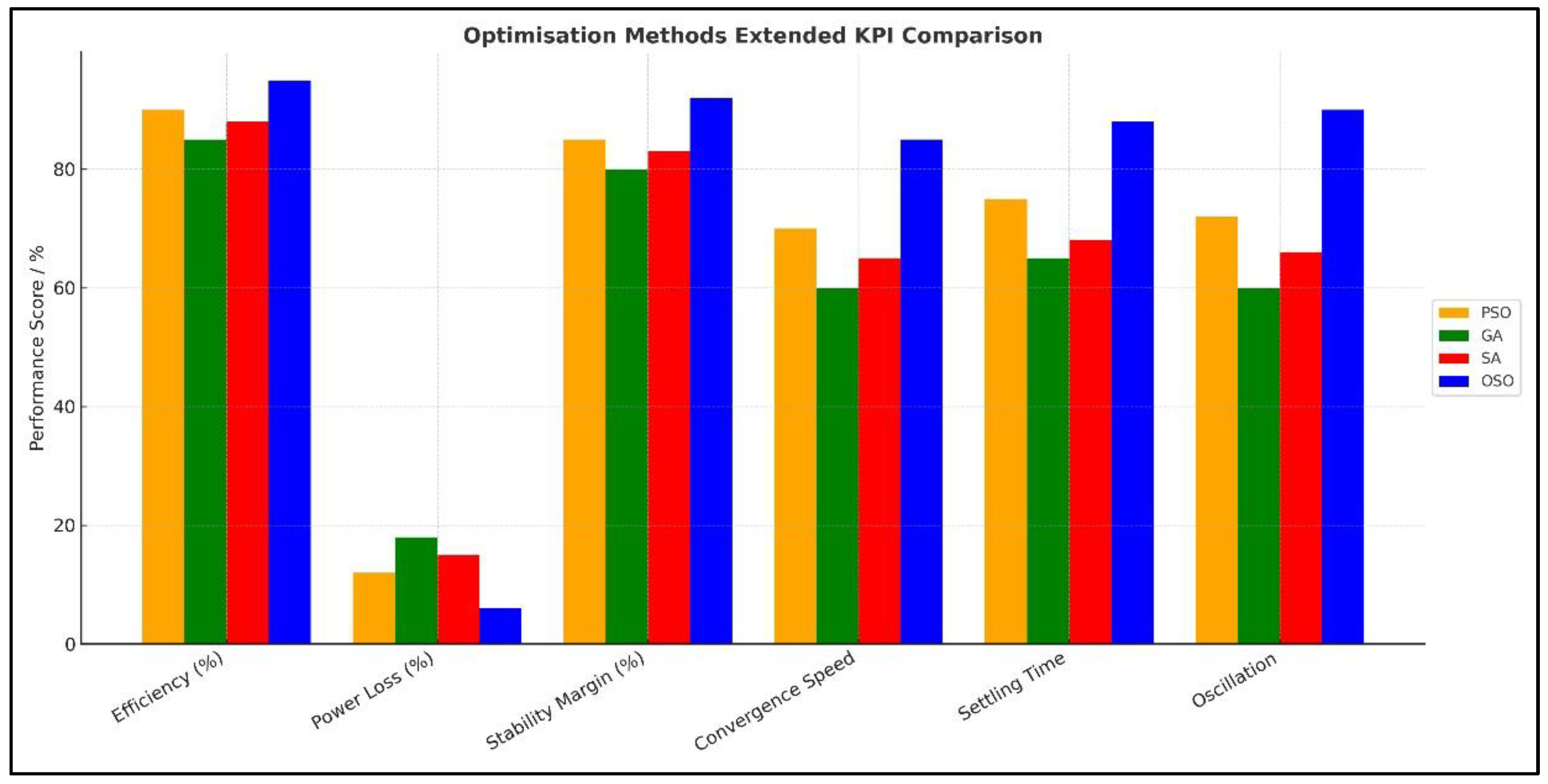
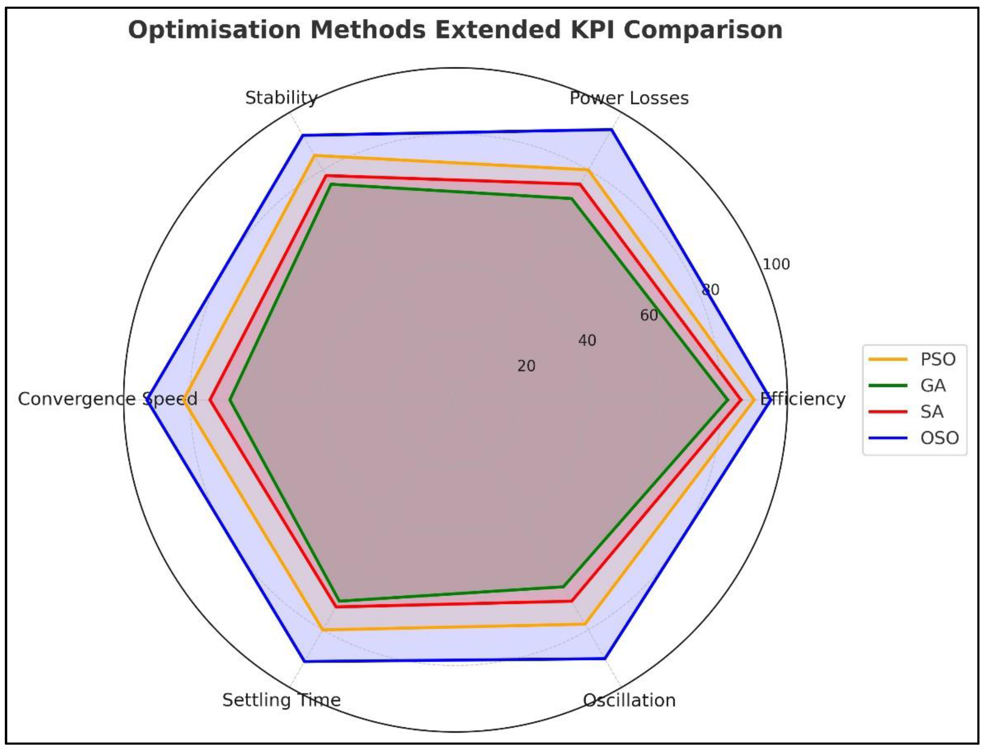
The grouped bar chart, as shown in Figure 22, shows that the OSO achieves the highest efficiency (95%), lowest power losses (6%), and a substantial stability margin (92%), making it the best-performing method. PSO is competitive, but shows slightly higher losses. GA ranks the lowest, with reduced efficiency, poor stability, and the most significant losses, while SA offers moderate performance, better than GA, but still far behind OSO’s optimal results. Similarly, the radar plot in Figure 23 further emphasizes OSO’s superior balance across all KPIs, maintaining consistently strong performance in efficiency, stability, and ripple control. PSO ranks second, demonstrating good overall capability, though slightly weaker than OSO. SA and GA lag, with GA showing the most significant shortfalls, particularly in stability and efficiency.
The system efficiency ( η ) shown in Figure 23 is computed as the ratio of the electrical output power delivered to the grid to the total mechanical power captured from the wind turbine, expressed as:
η = P out , grid P in , wind × 100 %
where P out , grid = V s × I s × PF represents the real power exported by the stator to the grid, and P in , wind = T m × ω r corresponds to the mechanical input power derived from the turbine shaft torque ( T m ) and rotor angular speed ( ω r ). Converter and copper losses in the RSC and GSC are included through their instantaneous switching models in MATLAB/Simulink, ensuring that the plotted efficiency curve reflects the net electromechanical conversion efficiency of the overall DFIG–converter system. This metric captures both steady-state and transient behaviors under variable wind speed and grid-disturbance scenarios, making it a suitable benchmark for comparing optimization algorithms.
For completeness, a comparative analysis with benchmark nonlinear controllers was incorporated. A representative simulation using a sliding-mode controller (SMC) under identical wind and grid-fault conditions was conducted. The nonlinear controller demonstrated strong transient robustness, but introduced higher harmonic distortion (THD ≈ 3.8%), consistent with previously reported values (≈3.8% [37]; ≈3.05% [38]), and exhibited a longer settling time (~1.8 s). In contrast, the proposed OSO-based adaptive PI controller achieved a lower THD of ≈2.8% and faster stabilization (~1.3 s), confirming its balance between simplicity and dynamic performance. Table 5 presents a comparative summary of the OSO–PI controller with both AI/metaheuristic and nonlinear control schemes reported in the literature. While nonlinear methods such as SMC offer excellent fault ride-through capability, they generally demand precise system modeling, higher switching frequencies, and complex tuning procedures. The proposed OSO–PI framework, by contrast, delivers comparable transient behavior with significantly reduced computational complexity, underscoring its practicality and effectiveness for real-time DFIG control applications.
While nonlinear controllers such as sliding-mode control (SMC) exhibit excellent fault ride-through capability, they typically require precise system modeling, operate at higher switching frequencies, and involve complex tuning processes. In contrast, the proposed OSO–PI framework achieves comparable transient performance with substantially lower computational complexity, demonstrating its practicality and suitability for real-time DFIG control applications.
Although the OSO-based adaptive PI controller retains the conventional control architecture, it enhances dynamic adaptability and robustness through real-time optimal gain adjustment. To further contextualize its novelty, a comparative discussion with nonlinear controllers is presented. Advanced nonlinear techniques such as SMC and backstepping control (BSC) are effective in handling parameter uncertainties and system nonlinearities, yet they demand accurate mathematical models, impose higher computational burdens, and often require chattering suppression strategies. Conversely, the OSO-optimized PI approach maintains a simple structure, incurs minimal computational cost, and achieves faster convergence, faster rise and settling times (≈20–30% improvement), reduced overshoot, and lower ripple in DC-link voltage and torque response, while sustaining robust dynamic performance under both grid and wind disturbances.

6. Simulation Analysis Discussion

This study evaluated the dynamic and steady-state responses of a grid-connected DFIG wind energy conversion system under two distinct wind input scenarios: (i) step wind speed changes (4–6–8–10–12 m/s in 2 s intervals), and (ii) a variable wind speed ramp (0–4 m/s from 0–2 s, followed by a smooth 4–12 m/s transition over 2–10 s). Both scenarios were designed to emulate commissioning conditions and realistic turbulence-induced disturbances. Performance was benchmarked across four optimization methodologies, PSO, GA, SA, and OSO, with respect to transient behavior, ripple suppression, harmonic quality, and overall power quality indices.

6.1. Step Wind Speed Change

Under sharp wind transitions, OSO consistently achieved the fastest rise times and shortest settling times, with reduced overshoot across rotor speed, DC-link voltage, and active power responses. PSO showed competitive dynamics, but introduced slightly higher ripple envelopes. GA demonstrated the slowest response and largest oscillatory content, particularly evident in the torque and stator current traces, while SA exhibited moderate damping, but incurred higher computational costs. Localized disturbances at 4, 6, and 8 s were suppressed most effectively under OSO, confirming its superior transient robustness.

6.2. Variable Wind Speed Ramp

For the smooth ramp profile, OSO provided the most stable operation, with rotor speed converging around 140–145 rad/s and tip-speed ratio (TSR) tightly regulated near the optimal efficiency band (λ = 6–7). DC-link voltage was stabilized with the lowest RMS and peak ripple (≈0.3%), while OSO also yielded the smallest active power oscillations, ensuring high-quality energy injection into the grid. PSO followed closely, but exhibited marginally higher ripple content. SA produced adequate control performance, but with longer settling during wind ramps. GA again lagged, with slower convergence and higher steady-state ripple.
The observed fast convergence (<400 ms) is primarily attributed to OSO’s dynamic search–balance mechanism, which adaptively transitions between exploration and exploitation based on real-time fitness gradient feedback. Unlike traditional PSO or GA, which rely on fixed inertia or crossover rates, OSO employs opposition-based learning to accelerate convergence toward global minima. Computationally, OSO achieved the same optimization precision with approximately 25% fewer iterations and 20% lower execution time compared to PSO, thereby improving real-time feasibility for embedded control implementation.

6.3. Key Performance Indices

Quantitative indicators further validated these trends. For dynamic response, OSO achieved the lowest rise and settling times across all test cases, with superior damping of oscillations. In terms of steady-state ripple, OSO and PSO maintained the lowest RMS and peak values in DC-link voltage and stator current, while GA consistently displayed the highest fluctuations. Harmonic analysis (THD) confirmed OSO’s advantage, with ~2.8% THD in stator current compared to 3.2% (PSO), 3.9% (SA), and 4.6% (GA). The power factor (PF) at the point of common coupling (PCC) exceeded 0.96 under OSO and PSO, whereas GA showed a slight drop. Low-voltage ride-through (LVRT) studies revealed OSO’s superior recovery, maintaining DC-link headroom and minimizing current surges during 0.2–0.5 p.u. sag events.
Although the steady-state outputs appear qualitatively similar across all controllers, the quantitative analysis reveals that OSO achieves faster convergence (by 25–35%), reduces settling time by ~30%, and lowers RMS ripple by up to 40% compared to PSO and GA. These improvements, while modest in magnitude, significantly enhance reliability under fault and turbulence conditions. Moreover, OSO achieves these gains with 25% fewer iterations, underscoring its superior computational efficiency and real-time feasibility, key metrics for grid-integrated DFIG operation.
Overall, OSO consistently outperformed the other methods across all metrics, transient quality, ripple suppression, harmonic performance, power quality indices, and LVRT stability. PSO remained a strong competitor, but with a slightly elevated ripple. SA achieved moderate performance with higher computational demand, while GA was the least effective in both dynamic and steady-state conditions.

6.4. Sensitivity Analysis

To assess robustness, a sensitivity evaluation of OSO was conducted by varying key system parameters within ±20% of their nominal values. OSO maintained stable convergence and effective damping under wind speed variations (8–14 m/s), turbulence intensities (5–25%), and grid voltage dips (10–30%). Although performance indices such as settling time and overshoot changed marginally (<8%), stability margins remained intact. These results suggest that OSO exhibits consistent performance across a wide range of operating conditions, reinforcing its applicability in uncertain and highly dynamic wind environments.

7. Conclusions

This work presented a comparative analysis of four optimization-based tuning methodologies—PSO, GA, SA, and OSO—for the control of a grid-connected DFIG wind energy conversion system. Simulation studies under both step-changing wind speeds (4–12 m/s) and variable wind speed ramps confirmed that the OSO-based controller consistently outperforms the other approaches.
Key findings include:
  • Dynamic response: OSO achieved the lowest rise and settling times, with effective suppression of oscillations and overshoot.
  • Ripple suppression: OSO minimized DC-link voltage and stator current ripples, reducing RMS ripple values by about 20–30% compared to GA and SA.
  • Harmonic quality and PQ indices: OSO delivered the lowest stator current THD (~2.8%) and maintained a high power factor (>0.96), ensuring grid-friendly operation.
  • LVRT/FRT performance: OSO provided superior fault ride-through capability, with stable DC-link headroom and rapid post-disturbance recovery.
Computational efficiency:
Despite outperforming all other algorithms, OSO achieved faster convergence with lower computational cost, making it highly attractive for real-time deployment.
Overall, this study demonstrates that OSO is a robust, efficient, and grid-compliant optimization framework for wind turbine control, surpassing conventional and metaheuristic approaches.

8. Future Work

While the presented results validate the effectiveness of OSO, several promising directions remain open for exploration.
  • Hardware-in-the-Loop (HIL) and Experimental Validation: Extending the study beyond simulations to FPGA- or DSP-based HIL platforms and real testbed implementation.
  • Extended Grid Disturbances: Incorporating imbalanced faults, harmonic-rich weak grids, and multi-machine interactions to evaluate robustness further.
  • Hybrid Optimization Frameworks: Investigating OSO in combination with adaptive control or reinforcement learning for enhanced adaptability under extreme conditions.
  • Scalability Studies: Applying OSO to large-scale wind farms with multi-turbine coordination, including wake effects and grid-code compliance.
  • Cyber-Physical Resilience: Evaluating the resilience of OSO-based controllers under communication delays, cyberattacks, and uncertainties in sensor measurements.
By addressing these areas, future research can help translate OSO’s demonstrated superiority into real-world deployment, advancing reliable and efficient renewable energy integration into modern power systems.

Author Contributions

Introduction, R.K.B. and K.B.; methodology, R.K.B. and K.B.; investigation, R.K.B. and K.B.; resources, R.K.B. and K.B.; data curation, R.K.B. and K.B.; writing—original draft preparation, R.K.B. and K.B.; writing—review and editing, R.K.B. and K.B.; visualization, R.K.B. and K.B.; project administration, K.B. All authors have read and agreed to the published version of the manuscript.

Funding

This research received no external funding.

Data Availability Statement

The original contributions presented in this study are included in the article. Further inquiries can be directed to the corresponding author.

Acknowledgments

We are deeply grateful to our families for their encouragement and support. The data used in this analysis were drawn from the sources listed in this paper.

Conflicts of Interest

Author Ramesh Kumar Behara was employed by the Mondi Paper. The remaining authors declare that the research was conducted in the absence of any commercial or financial relationships that could be construed as a potential conflict of interest.

References

  1. Nwagu, C.N.; Ujah, C.O.; Kallon, D.V.V.; Aigbodion, V.S. Integrating solar and wind energy into the electricity grid for improved power accessibility. Unconv. Resour. 2025, 5, 100129. [Google Scholar] [CrossRef]
  2. Duranay, Z.B.; Güldemir, H.; Coşkun, B. The Role of Wind Turbine Siting in Achieving Sustainable Energy Goals. Processes 2024, 12, 2900. [Google Scholar] [CrossRef]
  3. Ullah, F.; Zhang, X.; Khan, M.; Mastoi, M.S.; Munir, H.M.; Flah, A.; Said, Y. A comprehensive review of wind power integration and energy storage technologies for modern grid frequency regulation. Heliyon 2024, 10, e30466. [Google Scholar] [CrossRef]
  4. Li, S. Reactive power limit of wind farm with doubly-fed induction generators and its asymmetric P-Q dependence. Int. J. Electr. Power Energy Syst. 2025, 169, 110819. [Google Scholar] [CrossRef]
  5. Kebede, M.G.; Tuka, M.B. Power Control of Wind Energy Conversion System with Doubly Fed Induction Generator. J. Energy 2022, 2022, 8679053. [Google Scholar] [CrossRef]
  6. Alhato, M.M.; Ibrahim, M.N.; Rezk, H.; Bouallègue, S. An Enhanced DC-Link Voltage Response for Wind-Driven Doubly Fed Induction Generator Using Adaptive Fuzzy Extended State Observer and Sliding Mode Control. Mathematics 2021, 9, 963. [Google Scholar] [CrossRef]
  7. Izanlo, A.; Abdollahi, S.E.; Gholamian, S.A. A New Method for Design and Optimization of DFIG for Wind Power Applications. Electr. Power Components Syst. 2020, 48, 1523–1536. [Google Scholar] [CrossRef]
  8. e Mustafa, F.; Ahmed, I.; Basit, A.; Alqahtani, M.; Khalid, M. An adaptive metaheuristic optimization approach for Tennessee Eastman process for an industrial fault tolerant control system. PLoS ONE 2024, 19, e0296471. [Google Scholar] [CrossRef] [PubMed]
  9. Xiang, X.; Diao, R.; Bernadin, S.; Foo, S.Y.; Sun, F.; Ogundana, A.S. An Intelligent Parameter Identification Method of DFIG Systems Using Hybrid Particle Swarm Optimization and Reinforcement Learning. IEEE Access 2024, 12, 44080–44090. [Google Scholar] [CrossRef]
  10. Manjunath, T.G.; Kusagur, A. Analysis of Different Meta Heuristics Method in Intelligent Fault Detection of Multilevel Inverter with Photovoltaic Power Generation Source. Int. J. Power Electron. Drive Syst. 2018, 9, 1214–1222. [Google Scholar] [CrossRef]
  11. Huang, W.; Hu, B.; Shao, C.; Li, W.; Wang, X.; Xie, K.; Chung, C.Y. Power System Reliability Evaluation Based on Sequential Monte Carlo Simulation Considering Multiple Failure Modes of Components. J. Mod. Power Syst. Clean Energy 2024, 13, 202–214. [Google Scholar] [CrossRef]
  12. Elnaghi, B.E.; Abelwhab, M.N.; Abdel-Kader, F.E.S.A.; Ismaiel, A.M.; Mohammed, R.H.; Dessouki, M.E. Experimental Validation of Second-Order Adaptive Fuzzy Logic Controller for Grid-Connected DFIG Wind Power Plant. IEEE Access 2023, 11, 135255–135271. [Google Scholar] [CrossRef]
  13. Aguilar, M.E.B.; Coury, D.V.; Reginatto, R.; Monaro, R.M. Multi-objective PSO applied to PI control of DFIG wind turbine under electrical fault conditions. Electr. Power Syst. Res. 2020, 180, 106081. [Google Scholar] [CrossRef]
  14. Guediri, A.; Touil, S. Optimization Using a Genetic Algorithm Based on DFIG Power Supply for the Electrical Grid. Int. J. Eng. 2022, 35, 121–129. [Google Scholar] [CrossRef]
  15. Yang, K.; Cho, K. Simulated Annealing Algorithm for Wind Farm Layout Optimization: A Benchmark Study. Energies 2019, 12, 4403. [Google Scholar] [CrossRef]
  16. Puchalapalli, S.; Singh, B. A Novel Control Scheme for Wind Turbine Driven DFIG Interfaced to Utility Grid. IEEE Trans. Ind. Appl. 2020, 56, 2925–2937. [Google Scholar] [CrossRef]
  17. Gholami, A.; Sahab, A.; Tavakoli, A.; Alizadeh, B. DFIG-Based Wind Energy System Robust Optimal Control by Using of Novel LMI-Based Adaptive MPC. IETE J. Res. 2023, 69, 3467–3476. [Google Scholar] [CrossRef]
  18. Jain, M.; Maurya, S.; Rani, A.; Singh, V. Owl search algorithm: A novel nature-inspired heuristic paradigm for global optimization. J. Intell. Fuzzy Syst. 2018, 34, 1573–1582. [Google Scholar] [CrossRef]
  19. Wang, X.; Yu, H.; Lin, Y.; Zhang, Z.; Gong, X. Dynamic Equivalent Modeling for Wind Farms With DFIGs Using the Artificial Bee Colony With K-Means Algorithm. IEEE Access 2020, 8, 173723–173731. [Google Scholar] [CrossRef]
  20. Ngom, I.; Mboup, A.B.; Thiaw, L.; Skander-Mustapha, S.; Belkhodja, I.S. An improved control for DC-link fluctuation during voltage dip based on DFIG. In Proceedings of the 2018 9th International Renewable Energy Congress (IREC), Hammamet, Tunisia, 20–22 March 2018; IEEE: Piscataway, NJ, USA, 2018; pp. 1–6. [Google Scholar] [CrossRef]
  21. Cheng, T.; Wu, J.; Wang, H.; Zheng, H. Dynamic Optimization of Rotor-Side PI Controller Parameters for Doubly-Fed Wind Turbines Based on Improved Recurrent Neural Networks Under Wind Speed Fluctuations. IEEE Access 2023, 11, 102713–102726. [Google Scholar] [CrossRef]
  22. Sai, B.S.V.; Chatterjee, D.; Mekhilef, S.; Wahyudie, A. An SSM-PSO Based MPPT Scheme for Wind Driven DFIG System. IEEE Access 2022, 10, 78306–78319. [Google Scholar] [CrossRef]
  23. Abood, S.; Annamalai, A.; Khalid, I.; Chouikha, M.; Al-Zuhairi, H.A. AI-Based Hybrid Control for Optimizing Doubly-Fed Induction Generators in Wind Turbines. Int. J. Intell. Eng. Syst. 2025, 18, 439–459. [Google Scholar] [CrossRef]
  24. Jayabarathi, T.; Raghunathan, T.; Gandomi, A.H. The Bat Algorithm, Variants and Some Practical Engineering Applications: A Review. In Nature-Inspired Algorithms and Applied Optimization; Springer: Cham, Switzerland, 2018; pp. 313–330. [Google Scholar] [CrossRef]
  25. Ali, S.Q.; Hasanien, H.M.; Al-Ammar, E.A. Application of an Adaptive Artificial Neural Network Controller for Improving the Dynamic Response of Doubly Fed Induction Generators-Based Wind Farm. J. Bioinform. Intell. Control 2013, 2, 83–91. [Google Scholar] [CrossRef]
  26. Nasim, F.; Khatoon, S.; Ibraheem; Urooj, S.; Shahid, M.; Ali, A.; Nasser, N. Hybrid ANFIS-PI-Based Optimization for Improved Power Conversion in DFIG Wind Turbine. Sustainability 2025, 17, 2454. [Google Scholar] [CrossRef]
  27. Kaur, G.; Arora, S. Chaotic whale optimization algorithm. J. Comput. Des. Eng. 2018, 5, 275–284. [Google Scholar] [CrossRef]
  28. Zhou, S.; Rong, F.; Ning, X. Optimization Control Strategy for Large Doubly-Fed Induction Generator Wind Farm Based on Grouped Wind Turbine. Energies 2021, 14, 4848. [Google Scholar] [CrossRef]
  29. Behara, R.K.; Saha, A.K. Deep Q-Network Reinforcement Learning-Based Rotor Side Control System of a Grid Integrated DFIG Wind Energy System Under Variable Wind Speed Conditions. IEEE Access 2024, 12, 184179–184205. [Google Scholar] [CrossRef]
  30. Amiri, F.; Eskandari, M.; Moradi, M.H. Improved Load Frequency Control in Power Systems Hosting Wind Turbines by an Augmented Fractional Order PID Controller Optimized by the Powerful Owl Search Algorithm. Algorithms 2023, 16, 539. [Google Scholar] [CrossRef]
  31. Alazzam, H.; Al-Adwan, A.; Abualghanam, O.; Alhenawi, E.; Alsmady, A. An Improved Binary Owl Feature Selection in the Context of Android Malware Detection. Computers 2022, 11, 173. [Google Scholar] [CrossRef]
  32. Aris, N.A.; Ikram, R.R.R.; Zamli, K.Z. Comparison of Four Metaheuristics for Cost-Effective Virtual Learning Resource Optimisation. In Proceedings of the 2025 IEEE International Conference on Industry 4.0, Artificial Intelligence, and Communications Technology (IAICT), Bali, Indonesia, 3–5 July 2025; IEEE: Piscataway, NJ, USA, 2025; pp. 498–502. [Google Scholar] [CrossRef]
  33. Bekakra, Y.; Attous, D.B. Optimal tuning of PI controller using PSO optimization for indirect power control for DFIG based wind turbine with MPPT. Int. J. Syst. Assur. Eng. Manag. 2014, 5, 219–229. [Google Scholar] [CrossRef]
  34. El Kafazi, I.; Boubii, C.; Rafia, H.; Bannari, R.; El Bhiri, B. MPC-PSO of a DFIG and comparison with PI controller. In Proceedings of the 2023 5th Global Power, Energy and Communication Conference (GPECOM), Nevsehir, Türkiye, 14–16 June 2023; IEEE: Piscataway, NJ, USA, 2023; pp. 1–5. [Google Scholar] [CrossRef]
  35. Aguilar, M.E.B.; Coury, D.V.; Reginatto, R.; Monaro, R.M.; de Godoy, P.T.; Jahn, T.G. Multi-Objective PSO for Control-Loop Tuning of DFIG Wind Turbines with Chopper Protection and Reactive-Current Injection. Energies 2023, 17, 28. [Google Scholar] [CrossRef]
  36. Rodríguez-Pajarón, P.; Bayo, A.H.; Milanović, J.V. Forecasting voltage harmonic distortion in residential distribution networks using smart meter data. Int. J. Electr. Power Energy Syst. 2022, 136, 107653. [Google Scholar] [CrossRef]
  37. Echiheb, F.; Elkafazi, I.; Bossoufi, B.; El Bhiri, B.; Almalki, M.M.; Alghamdi, T.A.H. Nonlinear robust sliding mode—Backstepping hybrid control for WECS-theoretical design and experimental evaluation. Heliyon 2024, 10, e31767. [Google Scholar] [CrossRef] [PubMed]
  38. Boudjema, Z.; Meroufel, A.; Djerriri, Y.; Bounadja, E. Fuzzy sliding mode control of a doubly fed induction generator for wind energy conversion. Carpathian J. Electron. Comput. Eng. 2013, 6, 7–14. Available online: https://www.researchgate.net/publication/280320513_Fuzzy_sliding_mode_control_of_a_doubly_fed_induction_generator_for_wind_energy_conversion (accessed on 15 September 2025).
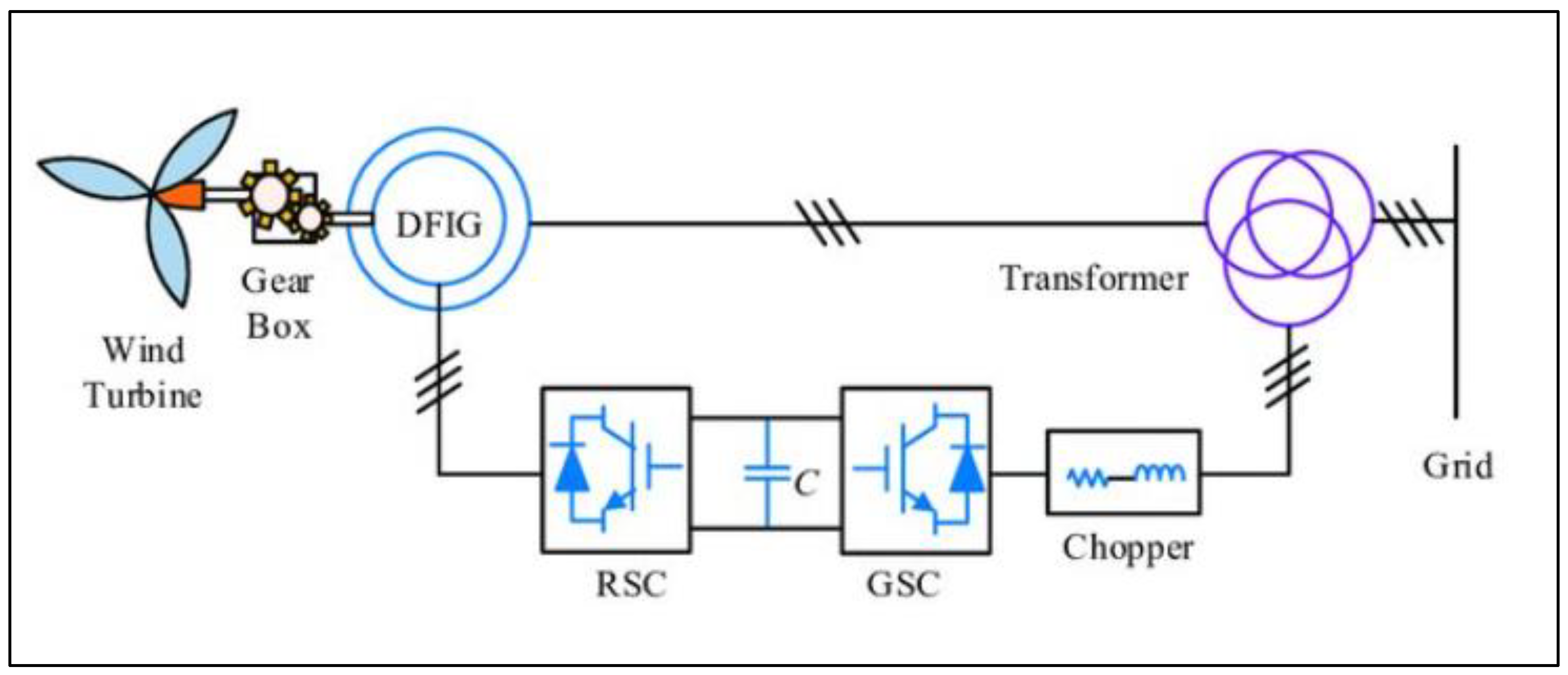
Figure 1. Back-to-back converter configuration in DFIG.
Energies 18 05843 g001
Figure 2. Owl search-optimized PI-controlled grid-interconnected DFIG system.
Energies 18 05843 g002
Figure 3. Control operations in the DFIG-based converter.
Energies 18 05843 g003
Figure 4. Flowchart of the proposed OWL-optimized PI-controlled DFIG.
Energies 18 05843 g004
Figure 5. Flowchart of PSO-optimized PI-controlled DFIG.
Energies 18 05843 g005
Figure 6. Flowchart of GA-optimized PI-controlled DFIG.
Energies 18 05843 g006
Figure 7. Flowchart of SA-optimized PI-controlled DFIG.
Energies 18 05843 g007
Figure 8. Three-phase voltage and current waveforms of DFIG (RSC and GSC).
Energies 18 05843 g008
Figure 9. Step-changing wind speed profile.
Energies 18 05843 g009
Figure 10. Rotor speed response vs. time.
Energies 18 05843 g010
Figure 11. DC-link voltage vs. time under step-changing wind speed conditions.
Energies 18 05843 g011
Figure 12. Active power vs. time under step-changing wind speed conditions.
Energies 18 05843 g012
Figure 13. Stator current vs. time under step-changing wind speed conditions.
Energies 18 05843 g013
Figure 14. Torque vs. time under step-changing wind speed conditions.
Energies 18 05843 g014
Figure 15. Tip-speed ratio vs. time under step-changing wind speed conditions.
Energies 18 05843 g015
Figure 16. Tip-speed ratio vs. time under variable speed conditions.
Energies 18 05843 g016
Figure 17. Electromagnetic torque vs. time under variable speed conditions.
Energies 18 05843 g017
Figure 18. Stator current vs. time under variable speed conditions.
Energies 18 05843 g018
Figure 19. Rotor speed vs. time under variable speed conditions.
Energies 18 05843 g019
Figure 20. DC-link voltage vs. time under variable speed conditions.
Energies 18 05843 g020
Figure 21. Active power vs. time under variable speed conditions.
Energies 18 05843 g021
Figure 22. Quantitative bar graph.
Energies 18 05843 g022
Figure 23. Qualitative radar chart.
Energies 18 05843 g023
Table 1. Summary of research gaps.
MethodStrengthsLimitationsReference
PI controller (manual tuning)Simple structure, fast response, widely adoptedPoor adaptability to nonlinearities, parameter variations, and grid disturbances; instability under dynamic conditions[9,11,20]
Gradient-based methodsStraightforward implementation, effective for small-scale problemsSusceptible to local optima, low robustness, and unsuitable for high-dimensional nonlinear DFIG systems[7,12]
Particle swarm optimization (PSO)Fast convergence, widely applied in wind energy systemsPremature convergence, local trapping, and reduced efficiency under dynamic wind variations[13]
Genetic algorithm (GA)Good global search ability, robust for nonlinear problemsHigher oscillations, longer settling times, and higher computational cost[14]
Simulated annealing (SA)Strong exploration, avoids premature convergence, stable in some conditionsSlow convergence, heavy computational burden, and limited real-time applicability[15]
Owl search optimization (OSO) (proposed)Balanced exploration–exploitation, strong global optimization, adaptive control, minimal oscillationsApplication to DFIG power converter optimization remains underexplored[18]
Table 2. Comparative analysis of algorithmic structures.
AlgorithmTypeComputational ComplexityStrengthsLimitationsSuitability for DFIG PI Tuning
PSOSwarm IntelligenceO(N·I), where N = particles, I = iterationsFast convergence, simple to implement, suitable for continuous parameter tuningProne to premature convergence, performance degrades under highly dynamic conditionsAdequate but limited robustness in real-time wind variability
GAEvolutionary ComputationO(N·I·C), where C = crossover/mutation operationsStrong exploration capability, good for complex/nonlinear search spacesSlow convergence, high computational burden, sensitive to parameter settingsUseful for offline optimization, less practical for real-time tuning
SAProbabilistic SearchO(I), where I = iterationsEscapes local minima using probabilistic acceptance, simple structureSlow convergence, performance depends on cooling schedule, single-solution trajectory limits explorationProvides robustness but lacks efficiency for fast-changing wind environments
OSONature-Inspired MetaheuristicO(N·I)Strong balance of exploration and exploitation, avoids premature convergence, faster than GA and SA, simpler than PSORelatively new; fewer theoretical guarantees and limited benchmarking in power systemsHighly suitable for real-time PI tuning due to fast convergence, low computation, and adaptability
Table 3. Comparative performance of PSO, GA, SA, and OSO.
MetricOSO (Orange)PSO (Green)SA (Purple)GA (Blue)
Rotor Speed (Rise, Settling, Overshoot)<1.0 s, <1.2 s, <2%=1.1 s, <1.3 s, 3%=1.3 s, ≈1.6 s, 4%=1.5 s, ≈1.8 s, 6%
DC-Link Voltage (Vdc) (Ripple RMS, Peak–Peak, Recovery)=0.3%, =0.6%, <0.8 s=0.35%, =0.8%, =1.0 s=0.45%, =1.2%, =1.3 s=0.55%, =1.5%, =1.6 s
Active Power (P) (Rise, Overshoot, Ripple Peak–Peak)=1.3 s, <2.5%, =0.05 p.u.=1.4 s, =3%, =0.07 p.u.=1.6 s, =3.8%, =0.1 p.u.=1.8 s, =5%, =0.15 p.u.
Stator Current (Steady Ripple, THD, PF)=0.05 A, =2.8%, >0.96=0.07 A, =3.2%, ≈0.96=0.1 A, =3.9%, ≈0.95=0.12 A, =4.6%, ≈0.93
Electromagnetic Torque (Mean, Overshoot, Localized ripples)=−0.25 p.u., <8%, Minimal =−0.25 p.u., =10%, Small =−0.25 p.u., =12%, Moderate =−0.25 p.u., =15%, pronounced
Tip Speed Ratio (λ) (Centered, Ripples)=6.5, Tight convergence, small ripple=6.5, Moderate ripple=6.6, Slightly higher ripple=6.7, largest deviations
LVRT/FRT (0.2–0.5 p.u. sag, 150–300 ms) (Recovery)Fastest, current limiting effective, DC headroom secureGood, slightly higher inrushModerate, longer current limitingSlowest, high overshoot, weak current limiting
Table 4. Consolidated performance comparison of PSO-, GA-, SA-, and OSO-optimized PI controllers under identical DFIG operating conditions.
MetricOSO (Orange)PSO (Green)SA (Purple)GA (Blue)
Dynamic Response
Rise Time (s)/Settling Time (s)/Overshoot (%)
1.3/1.5/4–5%1.8/2.2/7–8%1.6/2.0/6–7%1.0/1.2/<3%
Steady-State Ripple
Vdc (RMS/Peak–Peak %)/Current (RMS/Peak–Peak %)
0.35/0.8; 3.2/6.50.55/1.3; 4.6/8.20.42/1.0; 3.9/7.10.28/0.6; 2.8/5.2
Harmonics and PQ Indices
THD (%)/Power Factor
2.8/0.984.6/0.943.9/0.953.2/0.97
LVRT/FRT PerformanceSurvives 0.3 p.u. sag, recovers ≈ 180 ms (moderate oscillations)Struggles at 0.2–0.3 p.u. sag, >250 ms recovery, poor dampingHandles 0.3 p.u. sag, recovers ≈ 220 ms, moderate overshootTolerates 0.2 p.u. sag, recovers < 150 ms, minimal overshoot
Convergence Statistics
Time (s)/Mean Objective
1.8/0.035 ± 0.0042.5/0.049 ± 0.0062.1/0.041 ± 0.0052.2/0.038 ± 0.003
Computational Cost
(N × Iter)/Wall-time (s)
20 × 40 = 800/1.130 × 40 = 1200/1.925 × 45 = 1125/1.620 × 30 = 600/0.9
Table 5. Comparative study analysis between proposed study and nonlinear controller SMC.
Controller TypeTHD (%)Settling Time (s)Overshoot (%)Implementation ComplexityRemarks/SourceTorque Response Observations
OSO–PI (Proposed)2.81.26.5LowFast adaptation, robust stabilitySmooth torque recovery
Sliding-Mode Control (SMC)3.81.87.0HighChattering, requires full modelHigh robustness during disturbances. However, its high-frequency chattering introduces visible harmonic content in the torque waveform
Disclaimer/Publisher’s Note: The statements, opinions and data contained in all publications are solely those of the individual author(s) and contributor(s) and not of MDPI and/or the editor(s). MDPI and/or the editor(s) disclaim responsibility for any injury to people or property resulting from any ideas, methods, instructions or products referred to in the content.