Abstract
This study presents a numerical investigation of a parabolic trough absorber tube equipped with a novel Angularly Segmented Ring Turbulator (ASRT), designed to enhance heat transfer through periodic flow disturbance and improved wall–fluid interaction. The proposed ASRT geometry consists of segmented annular rings arranged along the tube length, characterized by two key parameters: the number of angular segments per ring (Nr = 4, 6, 8) and the angular spacing of each segment (α = 20° and 40°). Three dimensional simulations were performed using the finite volume method under turbulent flow conditions, with Reynolds numbers ranging from 3300 to 11,000. A non-uniform solar heat flux, obtained via Monte Carlo Ray Tracing (MCRT), was applied as a boundary condition at the outer wall to replicate realistic solar concentration. The results reveal that the ASRT significantly improves convective heat transfer, with the Nusselt number ratio reaching up to 3.7 for α = 20° and Nr = 8. This enhancement is accompanied by a moderate rise in the friction factor ratio , reaching approximately 7.5 at Re = 3300, indicating efficient turbulence promotion with acceptable hydraulic penalties. The Performance Evaluation Criterion (PEC) ranges from 1.7 to 1.9, confirming the superiority of ASRT over the smooth tube.
1. Introduction
The escalating global energy demand and the environmental impact of fossil fuel consumption have intensified the transition toward clean and renewable energy sources [1,2]. Among them, solar energy has emerged as a promising alternative due to its abundance, sustainability, and potential to significantly reduce carbon emissions. In this context, solar thermal technologies have attracted growing attention for their ability to efficiently convert solar radiation into useful thermal energy. Among the various solar technologies, parabolic trough collectors (PTCs) represent the most mature and widely deployed system for concentrated solar power generation [3]. Their ability to effectively convert solar radiation into thermal energy makes them a key component in sustainable energy production and industrial heat applications [4]. To enhance the thermal performance of PTC systems, researchers have proposed various enhancement strategies over the past decades [5,6,7]. These approaches are generally classified into three categories: active, passive, and compound methods. Passive techniques, such as the use of fins, twisted tapes, and dimple turbulators [8,9,10,11,12], are often preferred due to their simplicity and reliability, although they can induce a higher pressure drop that limits their efficiency.
Recent studies have examined the impact of these modifications on the absorber tube of PTCs. For instance, Shaker et al. [13] conducted CFD simulations on a parabolic trough absorber tube equipped with helical twisted-tape inserts, reporting a 60% increase in the Nusselt number compared to a smooth tube, while the friction factor rose by about 40%. Similarly, Ahmed et al. [14] numerically investigated toroidal ring-type turbulators and found that the periodic rings significantly enhanced local mixing, leading to improved convective heat transfer and better thermal uniformity along the absorber tube. Vicente et al. [15] experimentally investigated the thermo-hydraulic behavior of helically dimpled tubes using water and ethylene glycol as working fluids for Reynolds numbers between 2000 and 100,000. Their results showed that dimples enhanced heat transfer by 150–350% while the friction factor increased by up to 250% compared with smooth tubes. The study concluded that deeper dimples and optimized pitch-to-diameter ratios yield superior thermal performance at the cost of higher pumping power. Kaood et al. [16] numerically analyzed the entropy generation in turbulent flow through conical tubes with dimples using the realizable k–ε model within ANSYS Fluent. The study covered Reynolds numbers from 3 × 10³ to 4 × 10⁴ and revealed that convergent dimpled tubes with diameter ratios between 1.5 and 3 achieved the best thermal performance. The results showed up to 50.5% and 3.6% reductions in the normalized entropy generation number compared with smooth configurations, confirming that optimized dimple geometry enhances both heat transfer and thermodynamic efficiency. Khetib et al. [17] numerically examined the effect of spherical grooves on the thermal–hydraulic and exergy performance of a parabolic trough solar collector using a hybrid MWCNT–Al2O3/water nanofluid. Simulations were performed for groove heights of 1.5–3.5 mm, Reynolds numbers between 5000 and 20,000, and nanoparticle volume fractions up to 3%. The optimal case at Re = 20,000 and φ = 3% achieved up to 88.42% improvement in heat transfer and 149.01% enhancement in exergy efficiency compared with the smooth configuration, confirming the strong potential of grooved surfaces for hybrid nanofluid-based PTCs. Mwesigye et al. [18] developed a multi-objective and thermodynamic optimization of a parabolic trough receiver equipped with perforated plate inserts, combining CFD, RSM, and the NSGA-II algorithm. The study optimized the plate orientation angle, spacing, and diameter across Re = 1.02 × 10⁴–1.36 × 10⁶ to minimize entropy generation while enhancing heat transfer. Results indicated an entropy reduction of 53% and a notable improvement in heat transfer performance, confirming that perforated plates can effectively balance thermal efficiency and fluid dynamic losses in PTC receivers. Esmaeili et al. [19] conducted a numerical investigation on a modified parabolic trough collector equipped with conical turbulators and hybrid nanofluids to assess their combined influence on heat transfer and entropy generation. The results demonstrated that the insertion of the conical turbulators enhanced the heat transfer coefficient by nearly 57%, while the total entropy generation decreased by approximately 33%. The authors emphasized that this hybrid enhancement technique significantly improved the thermodynamic performance of the PTC system under turbulent flow conditions. Song et al. [20] conducted a numerical investigation on photovoltaic thermal solar air heaters equipped with rectangular hole plates and baffles. Their results showed that the optimized configuration (Type III) achieved a reduction in pressure losses by 7.8–20.3% compared with the baseline design, while the thermal efficiency increased by 12.9–20% and the exergy efficiency improved by 5.6–8.9%. These findings confirm that geometric modifications of internal structures can markedly enhance the thermohydraulic performance of solar thermal systems. Bellos et al. [21] investigated the thermal enhancement of parabolic trough collectors (PTCs) by combining nanofluids with a converging–diverging absorber tube. Their results revealed that the use of Al2O3 nanoparticles dispersed in thermal oil improved the mean collector efficiency by 4.25%, while the application of a wavy (converging–diverging) absorber geometry increased it by 4.55% compared with the conventional smooth tube. Mahmoudi et al. [22] numerically analyzed the thermo-hydraulic performance of nanofluid-based linear solar receiver tubes equipped with forward perforated ring steps with a triangular cross-section. Their results indicated that the use of CuO–water nanofluid achieved the highest performance, with the thermal efficiency reaching 76.5% at a Reynolds number of 200,000 when the ring step diameter equaled the tube diameter (D = d). Increasing the nanoparticle concentration from 1% to 4% enhanced the thermal efficiency by approximately 3%, while reducing the step spacing significantly increased both the Nusselt number and friction factor. Otmani et al. [23] experimentally analyzed the optical and thermal behavior of a parabolic trough collector prototype tested under North African climatic conditions. Five receiver configurations were compared, revealing that the three-tube receiver with a central black-coated tube achieved the highest thermal efficiency of about 85%, owing to improved solar ray focusing and uniform temperature distribution. The study highlighted the importance of receiver design in enhancing optical capture and overall PTC performance.
According to the aforementioned investigations, enhancing the thermal and hydraulic performance of parabolic trough collectors (PTCs) remains a crucial challenge for improving their overall energy efficiency and economic feasibility. However, to the authors’ knowledge, there is a lack of numerical studies addressing the effect of periodically segmented ring-type inserts within the absorber tube. Therefore, the present study introduces a novel geometric concept termed the Angularly-Segmented Ring Turbulator (ASRT) to intensify convective heat transfer while maintaining acceptable pressure losses. The main objective of this work is to examine the influence of the ASRT configuration on the hydrothermal performance of a PTC absorber under turbulent flow conditions with Reynolds numbers of 3300, 5500, 7500, and 11,000. The analysis considers a non-uniform heat flux distribution applied along the absorber wall to replicate realistic solar concentration effects. In this study, the hydrothermal characteristics are evaluated in terms of velocity and temperature contours, Nusselt number, friction factor, and overall thermal enhancement.
2. Geometric Model
The geometry of the investigated system is shown schematically in Figure 1. It consists of a parabolic trough collector with a reflective surface that concentrates solar radiation onto a steel absorber tube located along the focal line. The absorber tube is surrounded by a concentric glass envelope to minimize heat losses through convection and radiation. The main geometrical and optical specifications of the collector are summarized in Table 1. The absorber tube has a total length of 1.4 m, an inner diameter of 0.022 m, and an outer diameter of 0.026 m. Inside the absorber, a new Angularly Segmented Ring Turbulator (ASRT) is introduced, as shown in Figure 2. The turbulator consists of a series of annular rings arranged periodically along the tube axis with a pitch size of 0.04 m, giving a total of 31 rings along the entire length. Each ring is divided into several angular segments defined by the parameter Nr, which takes values of 4, 6, and 8. The angular spacing of each segment, denoted by the angle α, is varied between 20° and 40°. The geometric parameters used in this study are listed in Table 2.
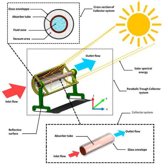
Figure 1.
Schematic representation of the parabolic trough collector system.

Table 1.
The specifications related to the collector size and its optical properties.
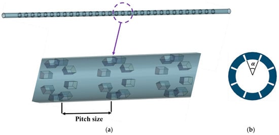
Figure 2.
Schematic representation of the absorber tube equipped with ASRT: (a) longitudinal arrangement and pitch distribution, (b) cross-sectional view showing the segmental angle (α).

Table 2.
Geometric specifications of the absorber tube equipped with the ASRT.
All geometries were generated using the Design Modeler module of ANSYS, maintaining identical tube diameter and length for all cases (Table 3).

Table 3.
Considered geometric configurations of the absorber tube equipped with ASRT.
3. Solution Method
This study is performed using a Computational Fluid Dynamics (CFD) approach implemented in ANSYS Fluent 19.2. The software solves the governing equations based on the finite volume method (FVM) to simulate the fluid flow and heat transfer characteristics within the absorber tube. The governing equations are solved under steady-state conditions and can be expressed as follows [24]:
Continuity equation:
Momentum conservation equation:
Energy conservation equation:
where ρ is the fluid density, u is the fluid velocity, p is the static pressure, µ is the dynamic viscosity, Cp is the specific heat capacity, k is the thermal conductivity, and T is the temperature. RNG turbulence model is adopted for all cases. The RNG transport equation for kinetic energy K and ε turbulence dissipation [25]:
where µeff represents the effective viscosity. The terms Gk and Gb represents the production of turbulent kinetic energy resulting from the mean velocity gradients and buoyancy effects, respectively. The parameter Ym accounts for the effects of the fluctuating dilatation in compressible turbulence on the overall dissipation rate. The coefficients αk and αε correspond to the inverse effective Prandtl numbers for k and ε, respectively. Sk and Sε are user-defined source terms included in the model formulation.
And
where η represents the dimensionless strain parameter and S denotes the mean rate strain magnitude. The constants used in the turbulence model are given as below:
Cµ = 0.0845, σk = 0.7194, σε = 0.7194, C1ε = 1.42, C2ε = 1.42, η0 = 4.38, β = 0.012
The Semi-Implicit Method for Pressure-Linked Equations (SIMPLE) algorithm was employed to establish the coupling between pressure and velocity fields, thereby ensuring mass and momentum conservation throughout the computational domain [26,27]. The Quadratic Upstream Interpolation for Convective Kinematics (QUICK) scheme was adopted for the discretization of convection terms, while a second-order central difference was used for the diffusion terms to maintain both accuracy and numerical stability. The convergence criteria for the continuity, momentum, energy and turbulence (k and ε) equations were set to 1 × 10⁻⁶, ensuring reliable and stable solutions for all simulated cases.
3.1. Boundary Conditions
The numerical simulation was configured by applying a non-uniform wall heat flux on the outer surface of the absorber tube. This heat flux was implemented through a User Defined Function (UDF) generated from the Monte Carlo Ray Tracing (MCRT) analysis. The MCRT computation accounted for the optical behavior of the collector system, including mirror reflectivity, glass transmissivity, and absorber absorptivity, to determine the realistic circumferential distribution of absorbed solar energy [19,28]. The resulting flux profile was imposed as a boundary condition in ANSYS Fluent to accurately reproduce the solar irradiation pattern experienced by the outer absorber wall.
In the present model, both the solid wall and the fluid domains were explicitly solved using a Conjugate Heat Transfer (CHT) approach. The non-uniform solar heat flux derived from the MCRT analysis was applied to the outer surface of the absorber wall, while heat conduction through the solid wall and convective heat transfer within the fluid were simultaneously computed to capture the temperature coupling at the wall–fluid interface.
The circumferential heat-flux distribution applied to the absorber wall is illustrated in Figure 3, showing both the angular variation of absorbed solar flux (Figure 3a) and the corresponding three-dimensional wall heat flux distribution (Figure 3b). The MCRT model reveals a highly non-uniform profile, with the maximum heat flux reaching approximately 3 × 10⁴ W/m2 in the illuminated zone (θ = 80–110°). The flux intensity progressively decreases toward the shaded region near θ = 180°, where the value drops below 5 × 10³ W/m2. This spatially varying heat-flux pattern clearly illustrates the circumferential thermal gradient induced by optical concentration, which governs the non-uniform heating behavior of the absorber surface. The non-uniform solar heat-flux profile obtained from the MCRT computation is consistent with the general distribution trends reported in the literature for parabolic trough receivers. As observed by Esmaeili et al. [19] and Al-aloosi et al. [28], the flux exhibits a pronounced asymmetry, with the highest intensity concentrated on the upper illuminated region of the absorber and a gradual decrease toward the lower shaded side. This behavior reflects the intrinsic optical characteristics of parabolic trough concentrators and ensures the physical relevance of the imposed boundary condition.
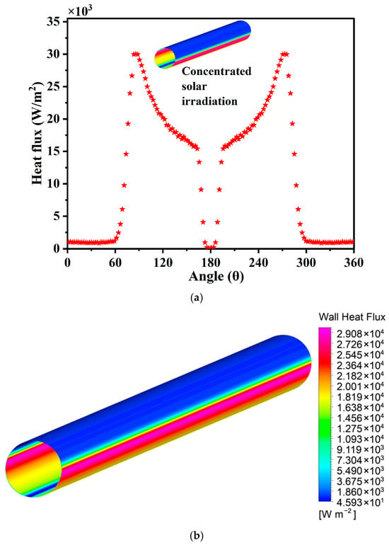
Figure 3.
Circumferential distribution of solar heat flux on the absorber tube obtained by the MCRT method: (a) angular variation of solar heat flux and (b) three-dimensional contour of the non-uniform wall heat flux applied in Ansys Fluent through a UDF.
At the inlet, water was introduced as the working fluid with uniform velocity values of 0.15, 0.25, 0.35 and 0.5 m/s corresponding respectively to Reynolds numbers of 3300, 5500, 7500, and 11,000. The inlet temperature was fixed at 300 K. At the outlet, a pressure outlet boundary condition with a fixed static pressure of 0 Pa gauche.
3.2. Parameter Definitions
This section presents the fundamental parameters and dimensionless quantities used to characterize the thermohydraulic performance of the present study.
The Reynolds number of fluid flow is defined as:
To calculate the Nusselt number
The friction factor is calculated as [29]:
where ΔP refers to the pressure drop along the tube.
It is worth highlighting that, for all absorber configurations equipped with toroidal rings, the overall thermohydraulic performance was assessed through the Performance Evaluation Criterion (PEC) [14]. This dimensionless parameter provides an integrated measure of heat transfer improvement while accounting for the associated hydraulic penalty, under identical pumping power conditions. A higher PEC value indicates that the modified configuration offers a more favorable balance between thermal enhancement and frictional losses compared to the smooth reference tube. The PEC at constant pumping power is expressed as [30,31]:
3.3. Grid Independence Study
The computational domain was discretized using ANSYS Meshing 2019, with a refined mesh near the absorber wall and the segmented annular rings to accurately capture strong gradients in temperature and velocity, while coarser elements were applied in the core flow region to reduce computational time (Figure 4). To verify grid independence, several mesh densities were tested, ranging from 5 × 10⁵ to 5 × 10⁶ elements. As shown in Figure 5, the Nusselt number (Nu) increases significantly with mesh refinement up to around 2.8 × 10⁶ elements, after which the variation becomes negligible. This indicates that the numerical solution is independent of further grid refinement. Therefore, the mesh containing approximately 2.0 × 10⁶ elements was selected for all subsequent simulations, providing a suitable compromise between accuracy and computational cost.
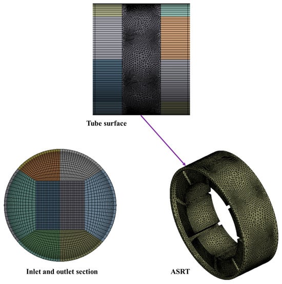
Figure 4.
Computational domain and mesh structure of the absorber tube with segmented annular rings.
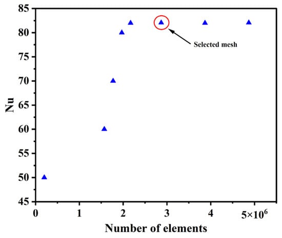
Figure 5.
Mesh independence test based on the variation of Nusselt number and friction factor with element count.
3.4. Model Validation
To ensure the reliability of the numerical model, the predicted results were compared with well-established empirical correlations for turbulent flow in smooth circular tubes. The average convective heat transfer was validated using the Gnielinski correlation for the Nusselt number, while the pressure loss was compared with the Filonenko correlation for the friction factor.
where the friction factor f′ is given by
The Filonenko relation for the friction factor is given by
The reliability of the numerical model was assessed by comparing the predicted results with the Gnielinski and Filonenko correlations, which are commonly applied to fully developed turbulent flow in smooth circular tubes. This reference case was used to evaluate the overall consistency of the thermal–hydraulic predictions of the present model.
To ensure the model’s applicability under non-uniform wall heat-flux conditions, additional comparisons were performed using available experimental and numerical results from [14,28,32,33] involving tubes equipped with various internal inserts such as helically corrugated surfaces, spring turbulators, and toroidal rings. These studies demonstrate similar thermofluidic behaviors under circumferentially varying heat flux, supporting the consistency and reliability of the present CFD model. As illustrated in Figure 6a, the Nusselt numbers predicted for the smooth tube agree well with the Gnielinski correlation, whereas the ASRT configuration exhibits a noticeable increase in convective heat-transfer performance. Figure 6b shows that the predicted friction-factor values are consistent with both the Filonenko relation and published data, with deviations remaining below 6%, confirming the numerical stability and accuracy of the adopted mesh.
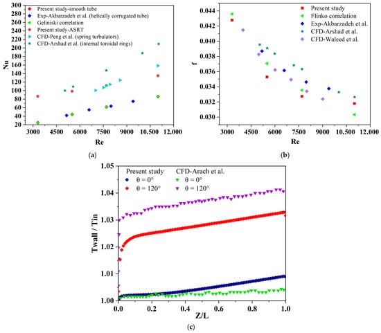
Figure 6.
Comparison between CFD results and standard correlations: (a) Nusselt number vs. Reynolds number; (b) friction factor vs. Reynolds number; (c) axial wall temperature ratio (Twall/Tin) for different circumferential angles. Present study (CFD) and comparison with experimental data of Akbarzadeh et al. [33] and numerical results of Peng et al. [32], Waleed et al. [28], Arshad et al. [14] and Arach et al. [10].
The wall temperature ratio presented in Figure 6c exhibits the same trend as the results of Arach et al. [10] for θ = 0° and θ = 120°. Slight differences are attributed to geometric variations between the models, but the overall temperature evolution remains consistent under similar flow conditions. The results demonstrate that the developed CFD model accurately captures both the thermal and hydrodynamic characteristics under non-uniform wall heating, ensuring its reliability for the subsequent analysis of the ASRT absorber.
4. Results and Discussion
In this section, the numerical findings derived from the CFD simulations are analyzed and discussed. The analysis investigates how variations in the Nr and the α influence the thermo-hydraulic behavior of the absorber tube equipped with the ASRT. The discussion encompasses the evolution of the internal flow field, turbulence intensity, and temperature distribution, followed by the assessment of key performance indicators, including the Nu, f, and PEC.
Figure 7 illustrates the velocity contours at the mid-section (700 mm) for the smooth tube and the ASRT configurations (Cases 1–6). The numerical analysis was conducted at a Re of 3300, corresponding to an inlet velocity of 0.15 m/s. In the smooth tube, the flow exhibits a classical parabolic velocity distribution, where the maximum velocity reaches approximately 0.26 m/s in the core region and progressively decreases toward the wall because of viscous effects. This uniform and symmetric pattern reflects a fully developed laminar to turbulent transition typical of low-Reynolds internal flows. When the ASRT inserts are introduced, the internal flow field becomes noticeably more complex. The segmented annular rings interrupt the boundary layer symmetry and generate localized recirculation zones downstream of each segment, enhancing axial momentum redistribution and promoting convective mixing. A comparison between Case 1 and Case 2, which isolates the effect of the Nr, shows that adding additional segments increases the number of small secondary vortices, yet their influence on the overall flow structure remains moderate. In contrast, comparing Case 1 and Case 4, which examines the influence of the α, reveals a substantial modification of the velocity field. Enlarging α widens the high velocity core region and intensifies the acceleration of fluid between adjacent ring gaps, leading to stronger shear layers and improved near-wall mixing. These results confirm that the combined increase in α promotes a more vigorous axial transport and better mixing between the core and near-wall regions, leading to a more uniform velocity distribution along the tube [34].
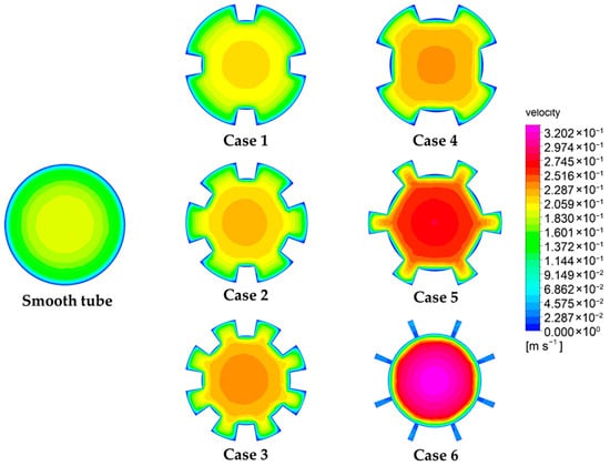
Figure 7.
Velocity contours at the mid-section (z = 700 mm) for the smooth and ASRT absorber tube configurations.
Figure 8 presents the turbulent kinetic energy (TKE) contours along the absorber tube for the smooth configuration and the six ASRT geometries (Cases 1–6). For the smooth tube, the turbulence intensity remains very low (around 6.4 × 10⁻⁷–9.4 × 10⁻⁴ m2/s2) and nearly uniform throughout the core, reflecting a laminar-like velocity field with negligible fluctuations. In Case 1, the introduction of four angularly segmented rings slightly enhances local turbulence downstream of each segment, forming small recirculating zones with limited interaction. As the number of rings increases (Cases 2 and 3), the TKE peaks rise to the order of 2.3 × 10⁻³–3.8 × 10⁻³ m2/s2, indicating the generation of stronger shear layers and enhanced energy dissipation near the ring edges. The influence of angular spacing becomes more evident in Cases 4 to 6, where larger angular offsets between successive rings promote a stronger periodic disturbance along the tube. In particular, Case 6 exhibits the most pronounced turbulent activity, with TKE values reaching approximately 7.0 × 10⁻³ m2/s2. This is attributed to the combined effects of increased angular spacing and multiple interacting vortices that intensify mixing and momentum exchange between the core and near-wall regions [35]. Overall, the ASRT configurations demonstrate a progressive amplification of turbulent energy with both the number of rings and angular spacing, confirming the geometry’s effectiveness in enhancing internal flow agitation and, consequently, convective heat transfer.
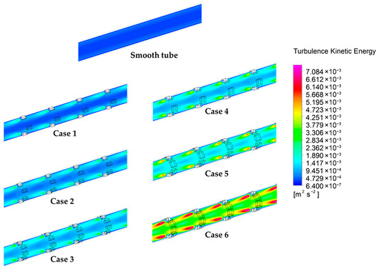
Figure 8.
Contours of turbulent kinetic energy (TKE) for the smooth and ASRT configurations.
Figure 9 depicts the temperature contours of the working fluid along the entire absorber tube for both the smooth configuration and the ASRT geometry (Case 6). The temperature scale ranges from 300 K to 307.9 K, illustrating the gradual thermal evolution of the fluid from the inlet to the outlet due to continuous heat absorption through the heated wall. In the smooth tube, the temperature field remains nearly uniform along the axis, with a limited rise of approximately 6–7 K, indicating weak convective mixing and a thick, undeveloped thermal boundary layer. In contrast, the ASRT configuration exhibits a more distinct temperature gradient, with higher wall temperatures and localized hot streaks forming behind each ring segment. These alternating hot and cold regions reveal the influence of flow separation and recirculation zones generated by the angularly segmented rings. The stronger near-wall convection and intensified axial mixing result in an overall temperature increase of nearly 8 K along the tube length, confirming the enhanced convective heat exchange. The zoomed view near the outlet clearly highlights this effect: the smooth tube preserves a relatively laminar thermal pattern, whereas the ASRT case shows periodic fluctuations in the temperature field due to the interaction between successive vortical structures. This periodic alternation of warm and cool streaks demonstrates the direct coupling between turbulence generation and heat transfer enhancement within the absorber.
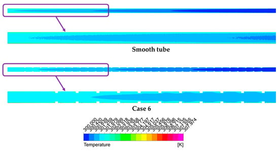
Figure 9.
Temperature contours of the working fluid along the entire tube, with a zoomed view near the outlet for the smooth and ASRT absorber configurations.
To facilitate comparison, the numerical results are expressed in dimensionless form using the normalized Nusselt number and the friction factor with respect to the smooth reference tube. The following discussion analyzes the influence of the geometric parameters, the Nr and the α, on flow resistance, heat transfer characteristics, and the PEC.
Figure 10 illustrates the variation of the with Re for the different ASRT configurations. In all cases, the friction ratio decreases steadily with increasing Re, which is consistent with the attenuation of viscous effects and the progressive stabilization of the turbulent boundary layer at higher flow rates. In the first group of cases (Figure 10b), where the α is kept constant at α = 10° and the Nr varies from 4 to 8, drops from approximately 6.0 → 4.0 for Case 3 and from 5.2 → 3.9 for Case 2 as Re increases from 3300 to 11,000. The increase in Nr enhances flow disturbance and generates additional wall shear, leading to a rise in between Case 1 (smooth) and Case 3 (8 rings). The second group (Figure 10a) highlights the influence of α while maintaining the same number of segments. When α increases from 10° to 20°, the friction factor rises noticeably due to stronger flow acceleration near the ring openings. At Re = 3300, reaches 7.5 for Case 6 (α = 20°, Nr = 8) compared to 5.8 for Case 3 (α = 10°, Nr = 10). A similar trend is observed for smaller Nr, where increases from 5.9 (Case 4) to 7.4 (Case 6) at low Re.
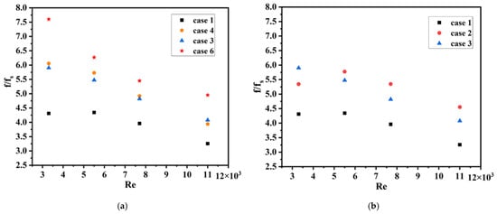
Figure 10.
Variation of the friction factor ratio with Reynolds number for different ASRT configurations. (a) Comparison among cases 1–6 for the first series of geometries; (b) Comparison among cases 1–3 for the second series of geometries.
Figure 11 displays the evolution of the as a function of the Re for all ASRT configurations. As expected, the heat transfer ratio tends to decline gradually with increasing Re, since the contribution of the geometric disturbances becomes less dominant once inertial transport strengthens. At lower Reynolds numbers, the flow is more responsive to the presence of the segmented rings, leading to a pronounced rise in the local turbulence intensity and stronger convective exchange between the wall and the core flow.
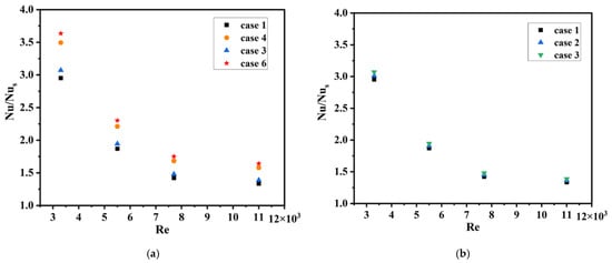
Figure 11.
Variation of the Nusselt number ratio with Reynolds number for different ASRT configurations. (a) Comparison among cases 1–6 for the first series of geometries; (b) Comparison among cases 1–3 for the second series of geometries.
In the configurations with a fixed inclination of α = 10° (Figure 11b), increasing the number of rings from 4 to 8 results in a modest improvement of the heat transfer performance. At Re = 3300, the ratio rises from 2.9 (Case 1) to 3.1 (Case 3). This trend suggests that beyond a certain number of rings, the additional disturbances overlap, creating periodic recirculation with limited incremental benefit. In contrast, when the inclination angle is doubled from 10° to 20° (Figure 11a), the enhancement becomes much more evident. The Nusselt ratio rises from approximately 3.1 (Case 3) to 3.6–3.7 (Case 6) at Re = 3300. The sharper inclination promotes fluid redirection toward the wall regions, strengthens the impingement effect behind the rings, and enhances the mixing intensity of the secondary vortices.
Figure 12 presents the variation of the PEC as a function of the Nr for two angles (α = 10° and 20°). The PEC reflects the combined effect of convective enhancement and frictional losses, providing a global indicator of thermal–hydraulic efficiency. As shown, all configurations equipped with ASRTs yield PEC values higher than unity, confirming that the heat transfer improvement outweighs the associated pressure-drop penalty. For α = 10°, PEC decreases slightly with increasing Nr, from about 1.82 for Nr = 4 to 1.70 for Nr = 8, indicating that adding more rings increases flow resistance more than it enhances turbulence. This suggests a threshold beyond which further segmentation provides diminishing returns in overall performance. Conversely, at α = 20°, PEC values remain consistently higher around 1.9–1.85 and show less sensitivity to Nr. The stronger α promotes vigorous secondary motion and efficient wall core mixing, leading to superior heat transfer efficiency despite the added shear losses. Compared to the lower angle cases, the gain in PEC reaches approximately 6–10%, highlighting the dominant role of α in optimizing the thermal hydraulic balance of the ASRT configuration. Overall, these results demonstrate that while increasing Nr alone does not guarantee improved global efficiency, an adequate combination of moderate segmentation and enhanced angular inclination yields the best trade-off between heat-transfer augmentation and pumping power.
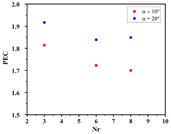
Figure 12.
Variation of the performance evaluation criterion (PEC) with the number of rings (Nr) for two angular spacings (α = 10° and 20°).
5. Conclusions
The present numerical investigation focused on assessing the thermo-hydraulic performance of a parabolic trough absorber tube equipped with the newly proposed Angularly-Segmented Ring Turbulator (ASRT). The effects of two geometric parameters, the number of segmented rings (Nr) and the angle of the ring segments (α = 10° and 20°) were analyzed under turbulent flow conditions for Reynolds numbers ranging from 3300 to 11,000. The results showed that the presence of ASRTs significantly enhances the fluid mixing and heat transfer in the absorber tube. The Nusselt number ratio reached up to 3.7 for the most efficient configuration (α = 20°, Nr = 8) compared to α = 10° at the same Nr. Meanwhile, the friction factor ratio increased by approximately 7.5 at a low Reynolds number (Re = 3300) for α = 20° compared to 5.8 for α = 10°, indicating that the improvement in thermal performance is accompanied by a moderate rise in flow resistance. The evaluation of the Performance Evaluation Criterion (PEC) confirmed that all ASRT configurations outperform the smooth tube, with PEC values between 1.7 and 1.9. The inclination angle α had a more pronounced impact than the number of rings, as increasing α improved turbulence generation and wall heat transfer without excessively penalizing the pressure drop. The optimum thermo-hydraulic trade-off was achieved for α = 20° and Nr = 4–6, representing an ideal balance between convective enhancement and pumping power. These findings demonstrate that the ASRT design is a promising passive enhancement concept for solar absorber tubes, capable of promoting intense secondary flows while maintaining acceptable hydraulic losses. Future work will focus on a systematic multi-objective optimization using the Response Surface Methodology (RSM) to determine the most influential geometric parameters and their interactions. This approach will enable the identification of an optimal ASRT configuration that maximizes both thermal efficiency and hydraulic performance within realistic design constraints.
Author Contributions
Conceptualization, M.S.K. and H.B.; Methodology, all authors; Software, M.S.K.; Validation, M.S.K., S.A. and O.R.; Investigation, O.R.; Resources, S.A. and L.C.; Writing—original draft, all authors; Writing—review & editing, Y.K., A.O. and H.B.; Supervision, S.A., L.C., O.R., I.B. and H.B. All authors have read and agreed to the published version of the manuscript.
Funding
This research received no external funding.
Data Availability Statement
The data presented in this study are available from the corresponding author upon request.
Conflicts of Interest
The authors declare no conflicts of interest.
References
- Hosouli, S.; Jahangir, M.T. Performance Evaluation of Novel Concentrating Photovoltaic Thermal Solar Collector under Quasi-Dynamic Conditions. Solar 2023, 3, 195–212. [Google Scholar] [CrossRef]
- Chavarría-domínguez, B.; De León-aldaco, S.E.; Ponce-silva, M.; Velázquez-limón, N.; Aguilar-jiménez, J.A.; Chavarría-domínguez, F.; Rodríguez-garcía, E.R.; Adamas-pérez, H.; Lozoya-ponce, R.E.; Flores-rodriguez, E. Performance Analysis of a Parabolic Trough Collector with Photovoltaic—Thermal Generation: Case Study and Parametric Study. Energies 2025, 18, 356. [Google Scholar] [CrossRef]
- Ebolese, A.; Marano, D.; Copeta, C.; Bruno, A.; Sabatelli, V. Numerical Modeling and Experimental Validation of Heat Transfer Characteristics in Small PTCs with Nonevacuated Receivers. Solar 2023, 3, 544–565. [Google Scholar] [CrossRef]
- Jayathunga, D.; Weliwita, J.A.; Karunathilake, H. Economic Feasibility of Thermal Energy Storage-Integrated Concentrating Solar Power Plants. Solar 2023, 3, 132–160. [Google Scholar] [CrossRef]
- Mahakud, J.; Kundu, B. Two-Dimensional Analysis of Absorber Plates in Solar Collectors with a Nonlinear Plate Temperature at the Tube Section. Energies 2024, 17, 5979. [Google Scholar] [CrossRef]
- Pourfallah, M.; Languri, E. Optimization of Heat Transfer in Parabolic Trough Collectors Using Advanced Turbulator Designs and Nanofluids. J. Energy Power Technol. 2025, 7, 003. [Google Scholar] [CrossRef]
- Phunapai, N. Optimizing Solar Parabolic Trough Receivers with External Fins: An Experimental Study on Enhancing Heat Transfer and Thermal Efficiency. Energies 2023, 16, 6520. [Google Scholar] [CrossRef]
- Huang, Z.; Yu, G.L.; Li, Z.Y.; Tao, W.Q. Numerical Study on Heat Transfer Enhancement in a Receiver Tube of Parabolic Trough Solar Collector with Dimples, Protrusions and Helical Fins. Energy Procedia 2015, 69, 1306–1316. [Google Scholar] [CrossRef]
- Khan, M.S.; Yan, M.; Muhammad, H.; Khuram, A.; Amber, P.; Anser, M. Comparative Performance Assessment of Different Absorber Tube Geometries for Parabolic Trough Solar Collector Using Nanofluid. J. Therm. Anal. Calorim. 2020, 142, 2227–2241. [Google Scholar] [CrossRef]
- Rezaei, A.; Ramin, G.; Khoshkhoo, H.; Joda, F.; Majidi, S. Thermo—Hydraulic Analysis of EuroTrough Solar Collector with Dimpled Absorber Tubes and Nanofluid: Coupling MCRT and CFD Methods. Heat Mass Transf. 2022, 58, 1829–1842. [Google Scholar] [CrossRef]
- Mustafa, J.; Alqaed, S.; Sharifpur, M.; Husain, S. The Effect of Using Multichannel Twisted Tape and Nanofluid on the Absorber Tube’ s Heat Transfer and the Efficiency of a Linear Parabolic Solar Collector. Sustain. Energy Technol. Assess. 2022, 52, 102329. [Google Scholar] [CrossRef]
- Waghole, D.R.; Shrivastva, R.K. Experimental Investigations on Heat Transfer and Friction Factor of Silver Nanofliud in Absorber/Receiver of Parabolic Trough Collector with Twisted Tape Inserts. Energy Procedia 2014, 45, 558–567. [Google Scholar] [CrossRef]
- Shaker, B.; Gholinia, M.; Pourfallah, M.; Ganji, D.D. CFD Analysis of Al2O3-Syltherm Oil Nanofluid on Parabolic Trough Solar Collector with a New Flange-Shaped Turbulator Model. Theor. Appl. Mech. Lett. 2022, 12, 100323. [Google Scholar] [CrossRef]
- Ahmed, K.A.; Natarajan, E. Thermal Performance Enhancement in a Parabolic Trough Receiver Tube with Internal Toroidal Rings: A Numerical Investigation. Appl. Therm. Eng. 2019, 162, 114224. [Google Scholar] [CrossRef]
- Vicente, P.G.; Garc, A.; Viedma, A. Heat Transfer and Pressure Drop for Low Reynolds Turbulent Flow in Helically Dimpled Tubes. Int. J. Heat Mass Transf. 2002, 45, 543–553. [Google Scholar] [CrossRef]
- Kaood, A.; Aboulmagd, A.; Eldegwy, A. Entropy Generation Analysis of Turbulent Flow in Conical Tubes with Dimples: A Numerical Study. J. Therm. Anal. Calorim. 2023, 148, 5667–5685. [Google Scholar] [CrossRef]
- Khetib, Y.; Sedraoui, K.; Melaibari, A.A.; Alsulami, R. The Numerical Investigation of Spherical Grooves on Thermal—Hydraulic Behavior and Exergy Efficiency of Two-Phase Hybrid MWCNT-Al2O3/Water Nanofluid in a Parabolic Solar Collector. Sustain. Energy Technol. Assess. 2021, 47, 101530. [Google Scholar] [CrossRef]
- Mwesigye, A.; Bello-ochende, T.; Meyer, J.P. Multi-Objective and Thermodynamic Optimisation of a Parabolic Trough Receiver with Perforated Plate Inserts. Appl. Therm. Eng. 2015, 77, 42–56. [Google Scholar] [CrossRef]
- Esmaeili, Z.; Akbarzadeh, S.; Rashidi, S.; Sadegh, M. Engineering Analysis with Boundary Elements Effects of Hybrid Nanofluids and Turbulator on Efficiency Improvement of Parabolic Trough Solar Collectors. Eng. Anal. Bound. Elem. 2023, 148, 114–125. [Google Scholar] [CrossRef]
- Song, Z.; Xue, Y.; Jia, B.; He, Y. Introduction of the Rectangular Hole Plate in Favor the Performance of Photovoltaic Thermal Solar Air Heaters with Baffles. Appl. Therm. Eng. 2023, 220, 119774. [Google Scholar] [CrossRef]
- Bellos, E.; Tzivanidis, C.; Antonopoulos, K.A.; Gkinis, G. Thermal Enhancement of Solar Parabolic Trough Collectors by Using Nano Fl Uids and Converging-Diverging Absorber Tube. Renew. Energy 2016, 94, 213–222. [Google Scholar] [CrossRef]
- Mahmoudi, A.; Fazli, M.; Reza, M.; Gholamalizadeh, E. Thermo-Hydraulic Performance Enhancement of Nano Fl Uid-Based Linear Solar Receiver Tubes with Forward Perforated Ring Steps and Triangular Cross Section; a Numerical Investigation. Appl. Therm. Eng. 2020, 169, 114909. [Google Scholar] [CrossRef]
- Otmani, A.; Benmehidi, N.; Seradg Mohamed Guedri, E.; Eddine, K.; Kahaleras, M.S. A Novel Tri-Pass Receiver Design for Parabolic Trough Collectors: Experimental Investigation and Thermal Analysis. J. Renew. Substain. Energy 2025, 17, 013703. [Google Scholar] [CrossRef]
- Dagdevir, T.; Keklikcioglu, O.; Ozceyhan, V. Heat Transfer Performance and Flow Characteristic in Enhanced Tube with the Trapezoidal Dimples. Int. Commun. Heat Mass Transf. 2019, 108, 104299. [Google Scholar] [CrossRef]
- Riaz, S.; Aaltonen, J.; Pinkse, T.; Koskinen, K. Parametric Study of Structural Influences on Suction Performance in an Annular Jet Pump—CFD and Experimental Validation. J. Water Process Eng. 2025, 70, 107066. [Google Scholar] [CrossRef]
- Ismail, A.H.A.O.A.; Kaood, A. Hydrothermal Performance Evaluation of Parabolic Trough Collector with Conical Dimpled Receiver. J. Therm. Anal. Calorim. 2025, 150, 6259–6286. [Google Scholar] [CrossRef]
- Abidi, A. Improving the Efficiency of Parabolic Solar Collector (PSC) Containing Magnetic Nanofluid with Absorber Pipe Equipped with Square Twisted Turbulator. Sustain. Energy Technol. Assess. 2022, 52, 102083. [Google Scholar] [CrossRef]
- Al-aloosi, W.; Alaiwi, Y.; Hamzah, H. Case Studies in Thermal Engineering Thermal Performance Analysis in a Parabolic Trough Solar Collector with a Novel Design of Inserted Fins. Case Stud. Therm. Eng. 2023, 49, 103378. [Google Scholar] [CrossRef]
- Kahaleras, M.S.; Layes, G.; Lanzetta, F.; Djetel-gothe, S. Applied Sciences Experimental Thermofluidic Characterization of Different Metallic Regenerators Crossed by Alternating Air Flow. Appl. Sci. 2022, 12, 4264. [Google Scholar] [CrossRef]
- Ghadirijafarbeigloo, S.; Zamzamian, A.H.; Yaghoubi, M. 3-D Numerical Simulation of Heat Transfer and Turbulent Flow in a Receiver Tube of Solar Parabolic Trough Concentrator with Louvered Twisted-Tape Inserts. Energy Procedia 2014, 49, 373–380. [Google Scholar] [CrossRef]
- Wang, L.; Sundcn, B. Performance comparison of some tube inserts. Int. Commun. Heat Mass Transf. 2002, 29, 45–56. [Google Scholar] [CrossRef]
- Yin, P.; Mohamed, Y.; Bashar, B.S.; Maher, M.; Zahra, A.; Mohammed, M.; Al, R.; Majed, H.; Alhani, I.; Salaam, E.; et al. Case Studies in Thermal Engineering Evaluation of Efficiency, Thermohydraulic Performance Evaluation Criterion, and Field Synergy Principle Improvement of the Parabolic Solar Collector Containing the Hybrid Nanofluid Using Spring Turbulators. Case Stud. Therm. Eng. 2023, 41, 102571. [Google Scholar] [CrossRef]
- Akbarzadeh, S.; Sadegh, M. Experimental Study on the Heat Transfer Enhancement in Helically Corrugated Tubes under the Non—Uniform Heat Flux. J. Therm. Anal. Calorim. 2020, 140, 1611–1623. [Google Scholar] [CrossRef]
- Wang, W.; Zhang, Y.; Li, B.; Li, Y. Numerical Investigation of Tube-Side Fully Developed Turbulent Flow and Heat Transfer in Outward Corrugated Tubes. Int. J. Heat Mass Transf. 2018, 116, 115–126. [Google Scholar] [CrossRef]
- Pethkool, S.; Eiamsa-ard, S.; Kwankaomeng, S.; Promvonge, P. Turbulent Heat Transfer Enhancement in a Heat Exchanger Using Helically Corrugated Tube. Int. Commun. Heat Mass Transf. 2011, 38, 340–347. [Google Scholar] [CrossRef]
Disclaimer/Publisher’s Note: The statements, opinions and data contained in all publications are solely those of the individual author(s) and contributor(s) and not of MDPI and/or the editor(s). MDPI and/or the editor(s) disclaim responsibility for any injury to people or property resulting from any ideas, methods, instructions or products referred to in the content. |
© 2025 by the authors. Licensee MDPI, Basel, Switzerland. This article is an open access article distributed under the terms and conditions of the Creative Commons Attribution (CC BY) license (https://creativecommons.org/licenses/by/4.0/).