Abstract
Thermal energy storage (TES) systems are crucial for industries to overcome the temporal misalignment between heat demand and availability, while also reducing greenhouse gas emissions. This is fundamental for increasing industrial production efficiency and promoting renewable energy sources, such as solar energy. Among various TES solutions (sensible, latent, and thermochemical), combined sensible/latent heat TES (CSLHTES) is attracting more interest. It combines the ideal characteristics of individual sensible or latent heat storage technologies: high stored energy density, compactness, high efficiency, stable heat supply temperature, and good power output. This work experimentally evaluates the thermal behavior and potential improvements of a CSLHTES system. This system, named HyTES, consists of two series-connected TES units—one sensible and one latent—operating within a 180–280 °C range, to meet typical industrial application requirements. A test procedure was developed to define key performance indexes (KPIs). The results confirm that CSLHTES systems generally show improved performance compared to individual units. This indicates that further analysis of this approach is justified, moving beyond just energy and exergy perspectives to also include economic and environmental impacts.
1. Introduction
1.1. Motivation
Worldwide, the generation of electrical power and thermal energy remains substantially reliant upon carbonaceous energy commodities: specifically, hard coal, methane, and petroleum-derived liquids [1]. Energy-related greenhouse gas emissions, like CO2 released into the atmosphere, contribute to global warming with serious consequences. These emissions can only be reduced through an increase in energy efficiency and the widespread use of renewable energy sources, which must also meet the world’s growing energy needs for electricity and heat [2]. Both energy efficiency (which involves the recovery of otherwise lost energy) and the use of renewable sources (where supply must meet user demand) require managing energy that is available but not immediately usable. Energy storage systems (ES) are key to achieving this [3]. Including a storage system in a renewable energy plant decouples the energy availability for the end user from the actual availability of the renewable source. This, in turn, allows for the large-scale use of renewable energy, with a consequent reduction in CO2 emissions [4,5].
Thermal energy makes up a substantial fraction of energy demand. It is used in diverse applications, from electricity generation (such as in CSP plants) to providing process heat for manufacturing goods and for building air conditioning. In most cases, the demand for heat is not constant, but characterized by various peaks.
Addressing the temporal misalignment between heat demand and availability necessitates the use of thermal energy storage (TES) systems. Such systems are crucial for shifting peak demand and optimizing demand management [6,7]. In fact, these storage systems offer CSP plants the advantage—compared to photovoltaic systems—of allowing electricity production when the sun’s radiation is absent through stored heat [8,9,10,11,12]. Additionally, TES systems enable the recovery of waste heat in different processes and industrial sectors [13] and are often designed in combination with heat pumps to increase their efficiency [14,15].
Notwithstanding extensive research endeavors in this domain [16], the successful assimilation of thermal energy storage (TES) technology into industrial operations is inherently challenging. This difficulty stems from the imperative for swift returns on investment and demonstrable profitability, which serve as crucial determinants for capital allocation decisions [17]. Consequently, the substantial preliminary capital outlay remains a considerable impediment [18,19,20]. Furthermore, owing to the inherent strengths and limitations of individual storage systems, their practical viability is acutely contingent upon specific process specifications and technical constraints, such as available energy conversion mechanisms and governing thermodynamic boundaries [17]. While typical industrial process infrastructure and energy provisioning systems exhibit a protracted operational longevity, spanning multiple years to several decades [21], process demands frequently undergo a more rapid evolution.
A TES system can store energy as sensible heat (sensible heat TES—SHTES), latent heat (latent heat TES—LHTES), or through thermochemical reactions. So far, the most commercial technology is certainly the sensible heat system, based on both solid and liquid storage materials. Latent heat systems are often used for low temperatures but are still being researched for medium to high temperatures. High-temperature thermochemical storage, on the other hand, is still at an early stage of research and will take time before becoming marketable. SHTES and LHTES can also be used in combination to meet specific requirements or applications.
1.2. Sensible Heat Thermal Energy Storage
Thermal energy storage in the form of sensible heat occurs through a change in internal energy—specifically, a temperature changing—in materials that do not undergo a simultaneous phase change [22]. The thermal energy content is quantified as the product of the substance’s mass, its mean specific isobaric heat capacity, and the temperature differential between the maximum and minimum temperatures reached by the storage medium. In addition to the average specific heat and density, other important properties for sensible heat storage include the following: the rate of heat extraction (a function of thermal conductivity and diffusivity), vapor pressure, corrosivity, the material compatibility of the system’s components, stability, the coefficient of thermal dissipation dependence upon the surface area-to-volume proportion, and crucially, cost. These systems are generally low-cost and do not require extensive fundamental research, though they still necessitate engineering and testing at both small and large scales. Water is considered the best candidate for sensible heat storage, due to its high heat capacity, cost-effectiveness, and large-scale availability. However, for temperatures above 100 °C under normal pressure conditions, materials such as oils, molten salts, and liquid metals and rigid media, such as mineral assemblages, advanced ceramic compounds, metallurgical alloys, concrete, etc., are used, with some materials being applicable up to 1000 °C [23].
A latent heat thermal energy storage system (LHTES) is based on the absorption or release of significant amounts of heat when the storage medium undergoes a phase change, typically solid–liquid or liquid–gas (or vice versa), within a small temperature range and at a quasi-isothermal transition. These materials are commonly referred to as phase change materials (PCMs).
Among the various technologies for thermal energy storage, LHTES systems offer a high energy storage density and have the advantage of charging and discharging a large amount of heat at an almost constant temperature during the melting and solidification of the storage medium [24]. The theoretical thermal energy stored in an LHTES system is given by the product of the latent heat of fusion (solid–liquid) and the molten mass of the PCM.
However, achieving a perfectly isothermal storage system at the phase change temperature is difficult, since the system typically operates over a temperature range that includes the melting point. In such cases, in addition to the latent heat, the contribution of sensible heat in both the solid and liquid states must also be considered.
Thermal energy supplied at a constant temperature and pressure can be fed to a turbine, allowing it to operate under optimal conditions. This is a significant advantage over sensible heat storage systems, where the temperature decreases as the thermal energy storage (TES) is discharged, unless costly double-tank systems are employed. Furthermore, utilizing an LHTES with a high melting point can significantly reduce the size of the energy storage system, limiting relative costs due to the high energy density associated with PCMs. The smaller container size also reduces heat loss to the surroundings by minimizing the external surface area. A key requirement for these systems is that the temperature of the heat transfer fluid (HTF) and the phase change temperature of the heat storage medium (HSM) are compatible.
Various categories of phase change materials (PCMs) are employed as a latent heat storage (LHS) medium, contingent upon the specific application and operational temperature regime. PCMs that undergo a liquid-to-gas phase transition, for instance, typically exhibit high transformation enthalpies, but introduce difficulties concerning the management of the heat storage material (HSM) in its gaseous state (e.g., inordinately large volumes and/or elevated pressures). Consequently, these materials are often impractical for a broad spectrum of uses. Conversely, PCMs that exhibit a solid-to-liquid change are generally considered more viable, as they secure a substantial quantum of stored thermal energy with a concomitantly minimal volumetric expansion that is correlated with the transformation.
PCMs are typically classified into three main categories: inorganic compounds, organic compounds, and eutectic compounds of inorganic and/or organic materials.
Inorganic compounds (salts, salt hydrates, and metals) are primarily characterized by high specific heat, high melting points, and high latent heat values, similar to those of organic compounds. Compared to organic PCMs, they also possess higher thermal conductivity, higher densities, and smaller volume variations. However, inorganic PCMs also exhibit disadvantages, such as a tendency toward undercooling and corrosiveness.
Although numerous substances have been contemplated and thoroughly examined for deployment in LHTES systems, only a limited number have reached the commercial application stage [25,26,27,28,29]. Persistent problems, which have not been completely overcome, include phase separation, undercooling, corrosion, long-term stability, and low thermal conductivity [30]. The most critical disadvantage regarding LHTES performance is the low thermal conductivity of most PCMs [24].
Various methods have been presented in the scientific literature to increase heat transfer between the heat transfer medium and the PCM [31]. Main strategies include the addition of fins or other extended surfaces [32,33,34], porous media [35], or nanoparticles [36,37] into the PCM.
1.3. Combined Sensible/Latent Energy Storage System Approache
In summary, for the two analyzed thermal storage technologies, sensible and latent, the main advantages and disadvantages can be summarized as follows:
- Sensible heat TES: These are the most commercially mature systems, easy to manufacture, based on easily available liquid or solid materials, with good specific heat values and thermal diffusivity (good power output) and a low cost. On the other hand, they have a low stored energy density and, consequently, a large volume requirement and high thermal losses (large exposed surfaces);
- Latent heat TES systems are highly advantageous for several reasons. They exhibit a high energy storage density due to latent heat, which results in great compactness and reduced thermal losses. In addition, they can supply energy at a nearly constant (or stabilized) temperature, thereby increasing the quality of the heat released (exergetic value). On the other hand, primarily due to the low thermal conductivity of the storage medium, these systems often face challenges such as lower power outputs, more complex heat exchange systems, and higher costs. Furthermore, corrosion problems can arise if the HSM (heat storage medium) is chemically aggressive.
An “ideal” thermal storage system should have characteristics that belong to one of the storage technologies, such as, for example: high stored energy density, compactness, high efficiency, stable temperature of the heat supplied, or good power supplied during the discharge phase. To achieve this goal, a combined sensible/latent heat thermal storage system in which both technologies coexist and contribute to the achievement of the indicated targets would be a useful solution [38,39,40,41].
Frazzica et al. [42] proposed an integrated solution of a container filled with a sensible heat storage medium and equipped near the outlet section, with a set of capsules containing a PCM. The testing of the small-scale sensitive/latent hybrid storage system used water, to which macro-encapsulated PCMs (commercial paraffin and hydrated salt mixture) were added inside the tank. The results showed a significant increase, up to 10%, in the capacity for volumetric energy retention, including in cases where restricted quantities of the phase change material were employed. Frazzica et al. [43] revived the same concept of hybrid storage, in which the macro-encapsulated PCM was evenly distributed within the container, along its entire length. This storage tank was developed specifically for the supply of hot water onboard ships, and was tested by selecting a commercial PCM on a laboratory scale. The obtained results showed the possibility of increasing the volumetric density of energy storage by up to 30% compared to the configuration with only sensible heat. Zauner et al. [44] investigated a hybrid sensible/latent heat storage concept based on a commercial shell and tube heat exchanger, in which the phase change material, high-density polyethylene (HDPE), is encapsulated within the tubes and the thermal oil acts as a sensible heat storage and heat transfer fluid. The research established the broad applicability of these energy storage technologies within various sectors, where the specifications for thermal capacity, temperature set points, power demand during cycling, and cost–benefit analysis exhibit substantial variation (specifically in renewable energy systems, industrial process heat, centralized district heating, electricity generation, and domestic heating). The study of a similar system was, therefore, carried out by Liu et al. [45] to implement a promising TES system for a CSP plant. They investigated the thermal behavior of different systems: cascade with three PCMs, cascade with five PCMs, hybrid PCM (Na2CO3-K2CO3)–graphite–PCM (Na2CO3-KCl-NaCl), and single graphite. All PCMs considered have proven to be potential storage media and can meet the operational requirements of the CSP. Comparing them, single graphite storage (sensible) was less problematic, but showed a lower storage density (47 kWh/ton). However, in a PCM–graphite–PCM (sensible/latent hybrid) sandwich configuration, the energy density is increased to 61 kWh/ton and the storage efficiency of this hybrid system reaches 70.7%, which constitutes the peak performance observed among the entire set of evaluated TES systems. On the other hand, the three PCMs in cascade (Na2CO3-K2CO3/NaCl-Na2CO3/Na2CO3-KCl-NaCl) and five PCMs, that added two worse identified molten salts, reached an energy density of 62 and 72 kWh/ton, and an efficiency of 61.7 and 54%, respectively. Due to their inherent properties, metals and metal alloys are evaluated as being highly favorable candidates for phase change materials (PCMs); these materials, in fact, had a much higher energy density (91 kWh/ton) and efficiency (57%) compared to the others.
In some cases, a single PCM is distributed in the sensible heat medium [46,47,48], while in others, the PCM is inserted in the inlet and/or outlet section of the container, effectively creating a multilayer or cascade system [49,50,51,52,53].
The differences between the proposed systems and the one proposed in this work lie mainly in the degree of integration between the sensible and latent heat storage materials.
In any case, creating systems in which the sensible and latent heat media were physically separated has only been imagined in a few cases: Becattini et al. [54] have implemented a combined sensible/latent TES system, consisting of two separate vessels—one for the sensible heat medium and one for the latent heat medium. A three-component thermal energy storage system was introduced by Laing et al. [55]. In this scheme, phase change material (PCM) storage is designated to manage the latent heat associated with two-phase evaporation, whereas a concrete storage element is employed for sensible heat accumulation, encompassing both water preheating and steam superheating. Furthermore, a pinch analysis serves to identify the boundary conditions between the solar collector array and the power block, thereby furnishing a framework for the dimensional specification of the latent and sensible storage units.
Stückle et al. [56] reported numerical simulations and a testing of a direct steam generation system; the TES module consisted of storage of both latent heat (NaNO3) and sensible heat, by means of high-temperature concrete.
JCA project [57] has been developing a thermal circuit equipped with a storage system, using two different modules including phase change materials, and one that is larger, consisting of cementitious material. Since the storage temperatures can reach 450 °C, the heat transfer fluid to be used for charging and discharging the modules is the so-called solar salt. The development of such a high-temperature TES (thermal energy storage) will allow for testing two important aspects:
- Integration of a thermocline cementitious module with two different kinds of PCMs;
- Performing experimental tests on cement materials in contact with molten salts, at a temperature of about 400 °C.
In general, the main reason for combining sensible/latent storage with separate sensible and latent containers can be summarized as follows:
- The cross-sectional area of latent storage can be different in size from that of sensitive storage and improve the heat transfer rate and melting of PCMs;
- It is possible to switch from an experiment with only the sensible or latent TES, or with the combined TES, by disconnecting and reconnecting the pipes connecting the two containers;
- The construction of a container for the PCM is easier than if the encapsulated PCM had been placed in the single container;
- At an industrial scale, the implementation of an independent latent heat reservoir simplifies the maintenance and exchange of the phase change material (PCM), primarily by obviating complications associated with inter-material corrosion between the PCM and its encapsulation;
- At an industrial scale, a separate sensible heat storage allows a possible packed bed simplified access (without an encapsulated PCM) to the upper part for the replacement of those rocks that can be degraded by higher temperatures.
For these reasons, CSLHTES systems, which use both sensible heat and latent heat, can be used in various applications where efficient, compact, and relatively stable TES are required. In fact, thermal energy storage (TES) is crucial across several sectors, notably in buildings for heating, cooling, domestic hot water, and enhancing thermal comfort. It is also essential for concentrated solar power (CSP) plants, guaranteeing continuous operation, and in industrial settings for recovering and reusing waste heat. Additionally, TES facilitates effective energy demand management by converting surplus electricity into heat (e.g., Carnot batteries), with materials like PCM being used for temperature stability in areas such as food preservation.
On the other hand, the separation of the sensible heat storage tank from the latent heat storage tank has the main disadvantage of increasing thermal losses, due both to the connecting pipes between the two containers and to the greater total surface area of the separate containers compared to the single one, and, consequently, an increase in material costs. In any case, this drawback could be overcome with design optimization.
In conclusion, the adoption of combined sensible/latent TES systems appears to be a good solution to obtain thermal storage with improved characteristics and, therefore, is worthy of further development.
1.4. Objective of This Work
In light of the previous, this research sets out to experimentally characterize the thermal behavior of a combined sensible/latent thermal energy storage (TES) system, assessing areas for potential improvement. This system is designed to operate in a temperature range between 180 °C and 280 °C, to meet the requirements of various applications, such as concentrating solar power (CSP) plants, processing heat, district heating/district cooling, and desalination. In contrast to the current literature’s findings, where the sensible and latent parts are often closely and physically integrated, it is hypothesized here that the two technologies are connected and operate in combination, but they remain physically separate (a cascade configuration, as illustrated in Figure 1).

Figure 1.
Combined sensible/latent TES system. Diagram with separate containers. Regarding the arrows: red for maximum, orange for average, and blue for minimum operating temperature.
Specifically, the combined sensible/latent heat TES, called HyTES, consists of two units connected in series: one consisting of a cement-based element, mainly using sensible heat, and the other with a latent heat element (PCM). In line with Beccantini et al.’s observations [54], this solution was adopted due to the industrial implementation advantages and disadvantages outlined in Table 1.

Table 1.
Advantages and disadvantages of a cascading sensitive/latent hybrid TES system with separate containers.
The experimental characterization will be accompanied by the preparation of a test procedure that is as rigorous as possible and aimed at determining the main key performance indexes (KPIs), a fundamental element to be able to compare different types of systems. Because there are currently no standardized test procedures to be used, it has been necessary to derive them by a recent IEC TS 62862-2-1:2021 standard [58], and the work elaborated by the SFERA-III project group [59].
1.5. Paper Structure
Following this introductory section, the article is organized into three main parts. Section 2 describes the HyTES system, detailing its constituent subsystems, the experimental setup, the test procedures, and the identified KPIs. Section 3 then presents and discusses the experimental results and calculates the KPIs that characterize the combined sensible/latent heat TES system. Finally, Section 4 summarizes the work and provides suggestions for future research.
2. Materials and Methods
In this chapter, the materials for thermal storage, the experimental setting, and the analysis methods used in the study are presented.
2.1. Heat Storage Materials
2.1.1. Phase Change Material
For the considered operating temperature range, the so-called “solar salt” was chosen as a phase change material (PCM); it is a mixture of sodium and potassium nitrates (60–40 wt% of NaNO3-KNO3), having the following basic characteristics at 240 °C: density 1946 kg/m3, thermal conductivity 0.463 W/(m·K), specific heat 1547 J/(kg·K) [60], latent heat of fusion 110 kJ/kg [61], it solidifies at 221 °C and starts to crystallize at 238 °C, dynamic viscosity 0.005015 Pa·s, solid–liquid volume change of 4.6% [62].
2.1.2. Concrete
As a sensible heat storage medium, a special concrete mixture was formulated with the help of the Calcestruzzi Cipiccia Spa company, located in Narni (Terni, Italy). This consists of a base concrete, to which 10% nominal weight of a micro-encapsulated PCM has been added [63]. The basic concrete mix has a low water/cement ratio (0.32) and has been designed to operate as a thermal storage medium at a temperature of at least 400 °C. It includes metal fibers, to promote thermal conductivity and increase the mechanical resistance of the material, and nylon fibers, to limit spalling phenomena. Micro-encapsulated PCM (mEPCM or SS-PCM) consists of the “solar salt” adsorbed by a porous medium, diatomite, in an 80:20 ratio [64]. A small amount of mEPCM has been incorporated into the base concrete, replacing some aggregates in an appropriate way. The main thermal and mechanical strength properties of this mixed design, after curing, degassing (105 °C), and heat treatment at 200 °C, are [63] as follows: density 2186 kg/m3, thermal conductivity 1.12 W/(m·K), specific heat 732 J/(kg·K), compressive strength 20.7 N/mm2, indirect tensile strength 2.77 N/mm2, and latent heat due to PCM 11 kJ/kg.
2.1.3. Thermal Oil
Therminol66® thermal oil (Eastman Chemical Company, Kingsport, TN, USA) was used in HyTES, both as a heat transfer fluid and, to a much lesser extent, as a thermal storage medium. It offers good performance up to 345 °C, including thermal stability and low vapor pressure. The main thermal properties can be extracted from the product data sheet [65].
2.2. Configuration of the Combined Sensible/Latent Heat Storage System
The combined sensible/latent heat TES system, examined here, is composed of two thermal storage units, one with sensible heat (SHTES) and one with latent heat (LHTES), connected in series. The two technologies, SHTES and LHTES, have been developed and characterized separately in a previous national project (ENEA-MiTE Program Agreement, PTR 2019-2021). A basic element (SH02) has been developed for sensible heat thermal storage [66], which uses the special concrete described above as HSM. On the other hand, for thermal storage with latent heat, the basic element (LH02) is a shell-and-tube type, using Solar Salt as PCM.
2.2.1. Sensible Heat Storage Unit
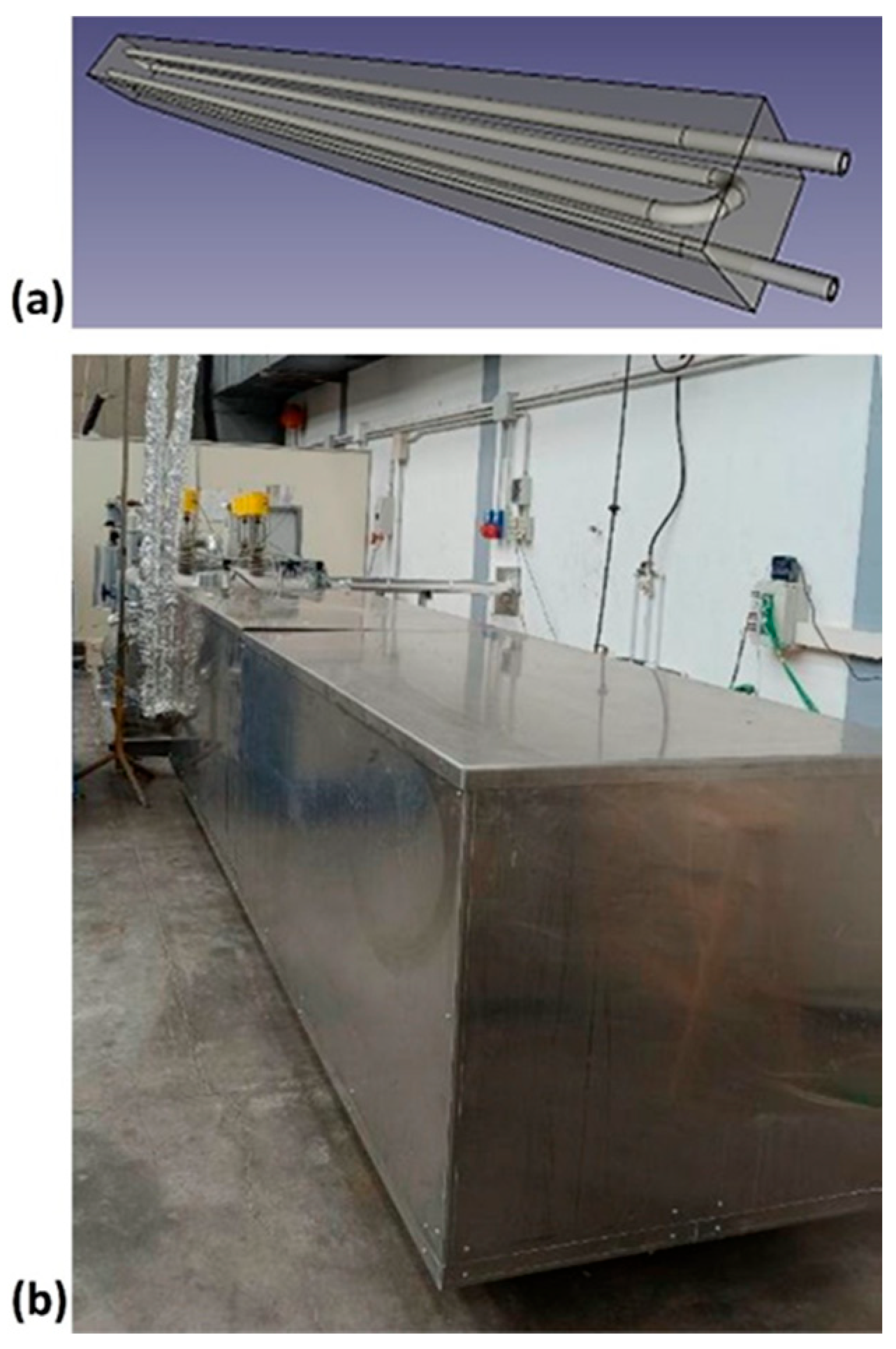
The ENEA-TES-SH02 thermal storage element [63] is designed to store thermal energy mainly in the form of sensible heat, by exploiting the thermal variation in the concrete. It has a parallelepiped shape with a square base (220 × 220 × 3000 mm) and is mainly made up of a metal heat exchange tube (Figure 2a) in AISI 304, with 16 mm external diameter, 1.5 mm thickness, and 11.9 m total length, and a heat storage medium (Figure 2b), formed by concrete. The heat transfer fluid, a diathermic oil, passes through the exchange tube, responsible for the transfer/recovery of heat to/from the storage medium. One device contains about 319 kg of concrete, of which about 25 kg is PCM, and a nominal heat capacity of 7 kWh, for the temperature range considered. Nominal heat capacity is the amount of thermal energy provided at a real full discharge, and it is different from theoretical capacity, which instead represents the ideal maximum thermal energy of the system when all its components, starting from the minimum operating temperature, reach the maximum temperature. The component is completed with an appropriate external thermal insulation (400 mm thick) to limit heat losses, including a protective sheet, support, and an instrument for temperature acquisition.
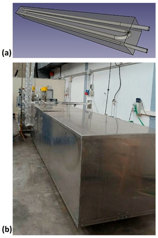
Figure 2.
ENEA-TES-SH02: (a) an image of the sensible heat thermal storage element; (b) the insulated SHTES prototype.
The insulation material is a rockwool by the Rockwool® group (Hedehusene, Denmark), with a density of 70 kg/m3, thermal conductivity of 0.035 W/(m·K), and heat capacity of 1030 J/(kg·K).
2.2.2. Latent Heat Storage Unit
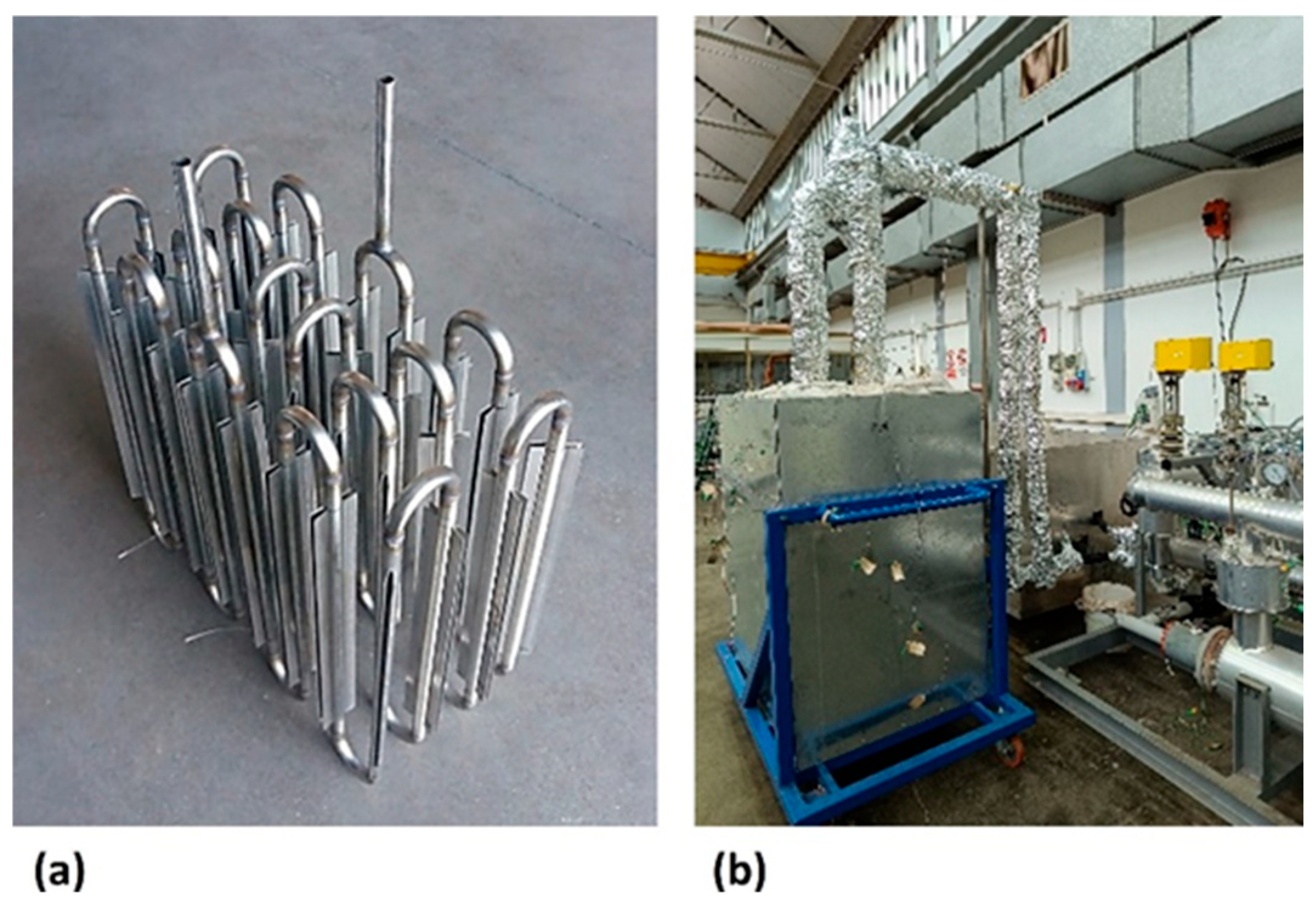
The ENEA-TES-LH02 thermal storage element is designed to store thermal energy, mainly in the form of latent heat, by exploiting the phase change in a PCM. It consists of a metal container in the shape of a parallelepiped (725 × 355 × 865 mm), to include the storage medium, and two AISI 304 serpentine pipes (20 mm external diameter and 2 mm thickness), arranged symmetrically with respect to the vertical median plane that cuts the larger base side (12.5 m long each one). The sections of vertical tube, to promote thermal conductivity in the storage medium, have four 500 mm-long longitudinal fins (20 high and 1 mm thick).
The prototype includes approximately 387 kg of sodium and potassium nitrate salt (solar salt). The thermal capacity for a temperature range of 200–300 °C is about 31 kWh, with approximately 40% (12 kWh) being latent heat. The component is enclosed in an appropriate external insulation (200 mm thick) to limit thermal losses, including the protective sheet, as well as supports and instrumentation for temperature acquisition (Figure 3).
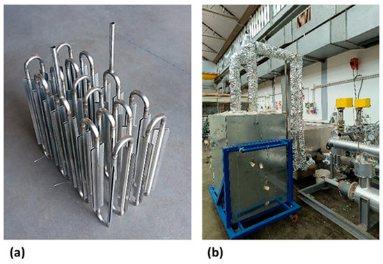
Figure 3.
ENEA-TES/LH02: internal thermal exchange pipe (a) and the LHTES prototype with insulation (b).
The insulation material is a Knauf® DP4, with a density of 40 kg/m3, thermal conductivity of 0.037 W/(m·K), and heat capacity of 1030 J/(kg·K).
The differences in the kind of insulation applied to the SH02 and LH02 are due to the different surface area to volume ratio. For the first device it is 18.85 m−1, while on the second one it is 10.7 m−1. In addition, the diffusivity of the solar salt is lower than the concrete (1.53 × 10⁻⁷ vs. 7.00 × 10⁻⁷ m2/s). In these conditions, as reported in Table 2, SH02 showed thermal losses of 257 W and 848 W, respectively, at 180 °C and at 280 °C, while LH02: 211 W was at 180 °C, and 299 at 280 °C. These results confirm the recommendation to reduce the surface-to-volume ratio as much as possible.

Table 2.
Composition of the heat stored in HyTES system at maximum and minimum operating temperatures.
2.3. The Experimental Apparatus
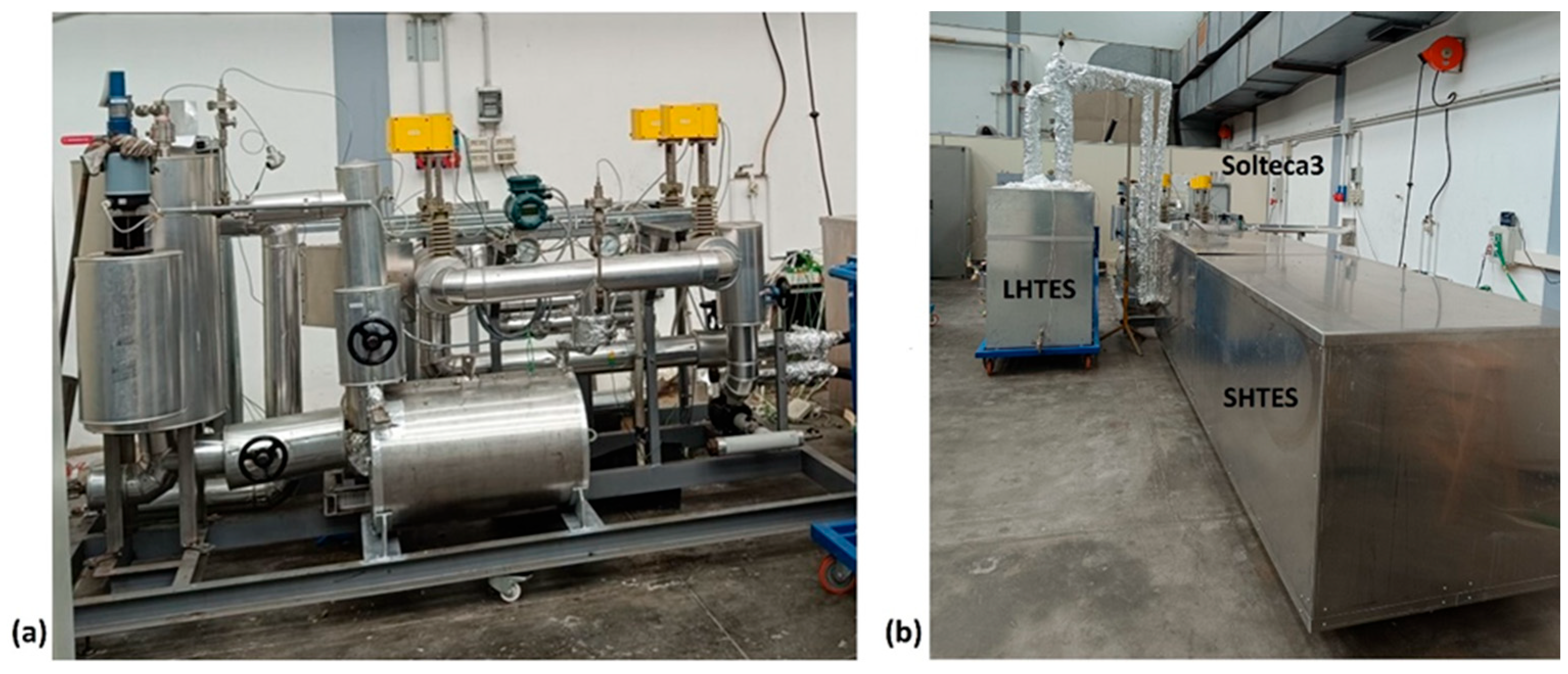
The experimental apparatus, named Solteca3, used to analyze the combined sensible/latent heat TES system, is located in Rome, at the ENEA Casaccia Research Centre (Figure 4).
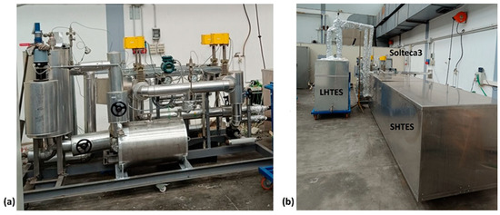
Figure 4.
Pictures of the Solteca3 experimental apparatus (a) and the assembled combined sensible/latent heat TES prototype (b).
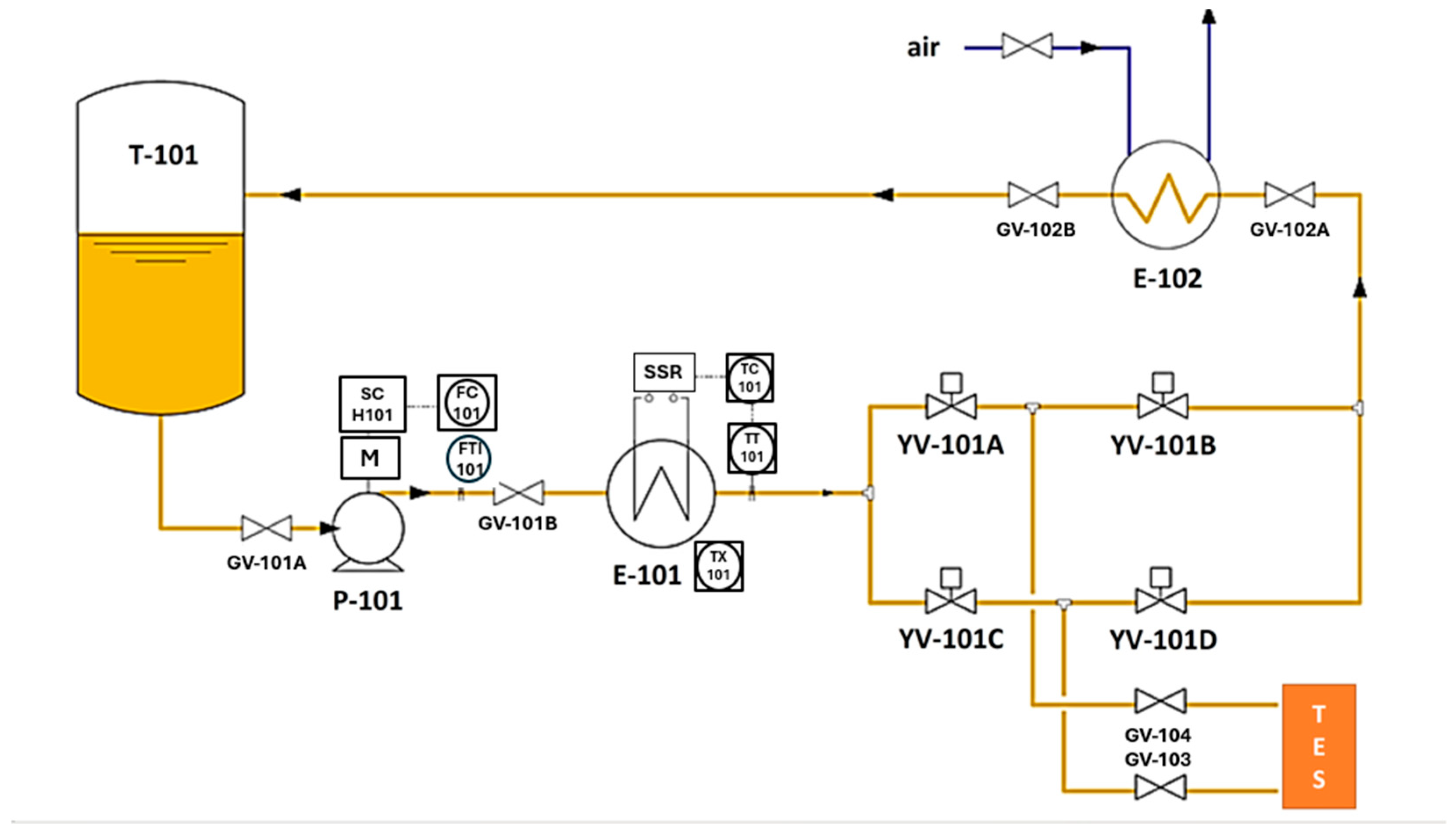
It was designed to perform experimental thermal charging and discharging tests up to 300 °C, using a diathermic oil as the heat transfer fluid, on small-to-medium sized thermal energy storage elements, under typical industrial plant conditions. The main components included in Solteca3 (Figure 5) are as follows:
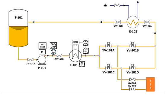
Figure 5.
Simplified diagram of the Solteca3 experimental apparatus.
- An oil tank (T-101) with a volume of approximately 50 L, operating at a maximum pressure of 0.5 bar, and equipped with a safety valve (PSV-101) and a level gauge (L-101).
- A magnetic drive centrifugal circulation pump (P-101), regulated by an inverter based on the flow rate set by the operator (0–1000 kg/h).
- An electric heater (E-101) with a power of 21 kWth, which allows the oil entering the TES to be heated to the desired temperature, provided it is below a set value (approximately 340 °C).
- An oil cooling circuit (heat exchanger E-102) that uses circulating air to reduce the temperature of the oil exiting the TES before it is returned to the tank. This cooling is necessary because of the heat extracted during the discharge phase.
- Four solenoid valves (YV-101A, YV-101B, YV-101C, and YV-101D), which allow for the correct circulation of the diathermic oil to heat or cool the oil and to charge or discharge the TES.
- Two valves (GV-103 and GV-104) are connected to the thermal storage system that will be characterized.
- K-type thermocouples, to detect the temperature related to the following point:
- 1 in the oil vessel;
- 1 after the E-101 exchanger (TT);
- 1 before and 1 after the cooling system;
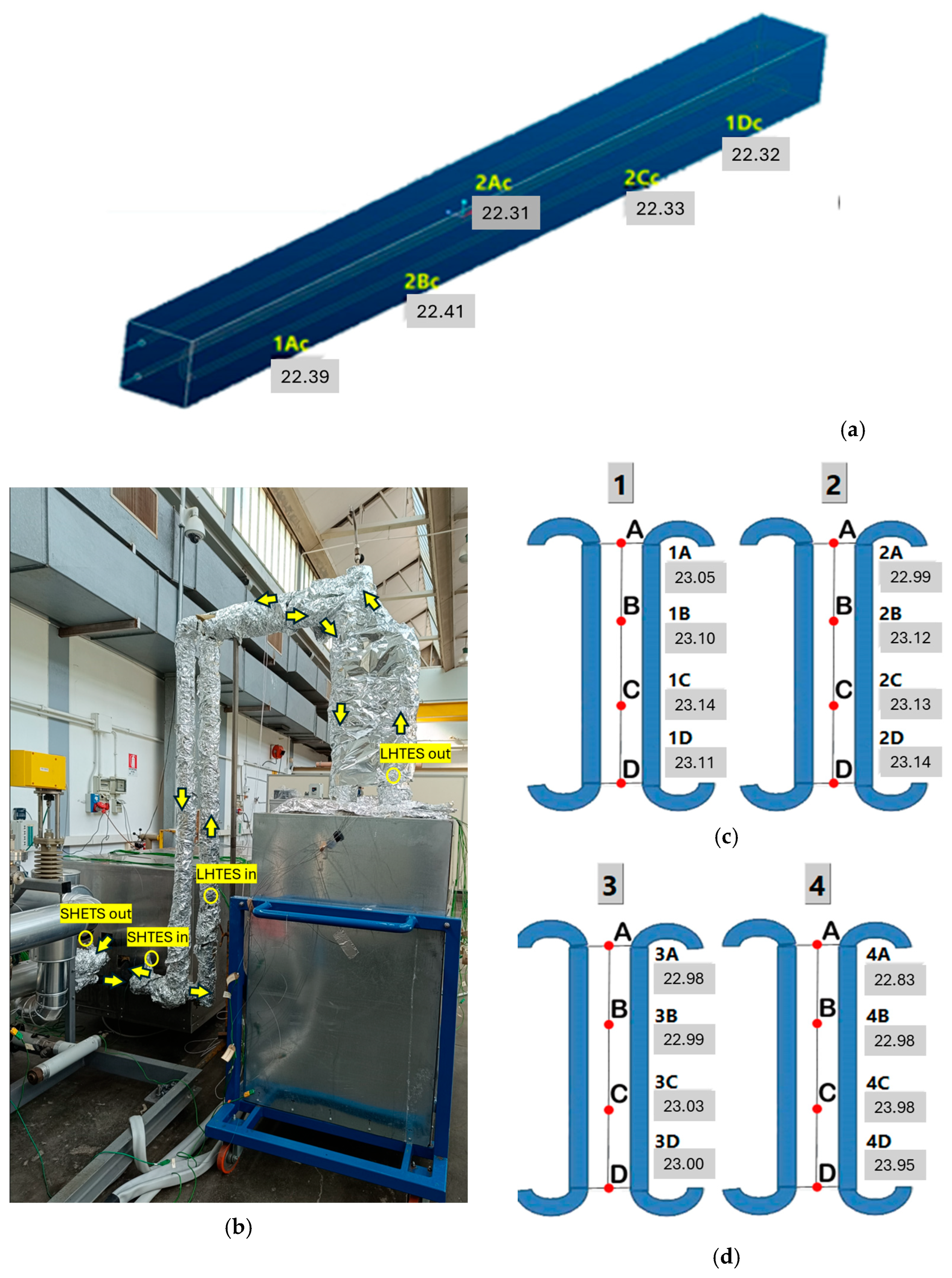
- 4 between SHTES and LHTES, as shown in Figure 6a. This image highlights the oil flow path during the charging process; the flow is reversed during discharge;
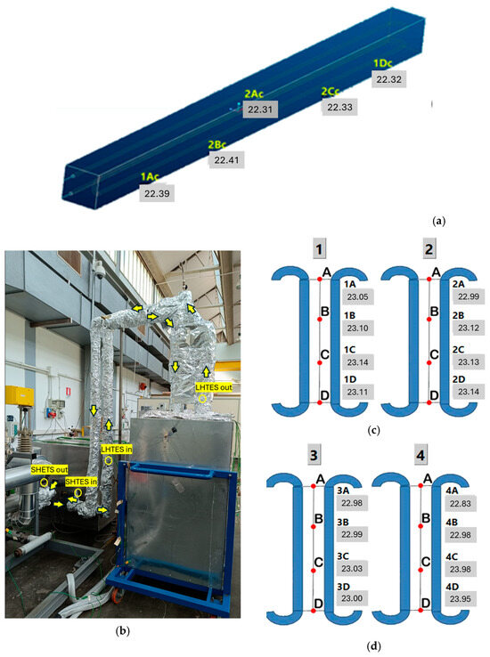 Figure 6. Positioning of the thermocouples in: SHTES (a); in the piping, they are highlighted by the yellow circles while the yellow arrows show the thermal oil flow in charging (b); in the internal part of the LHTES (showed by the red points) (c); in the external part of the LHTES (showed by the red points) (d).
 - 5 in the SHTES—4 located on the exchanger surface and one within the concrete (Figure 6b);
- 16 on an iron mesh installed within the PCM. They are located at equal distances between the vertical exchanger tubes installed in the LHTES (Figure 6c,d). The thermocouples are arranged across 4 different heights on 4 parallel rows of tube. Specifically, Figure 6c illustrates the thermocouples installed among the inner tube bundles (number 1 is on the right and 2 on the left), while Figure 6d shows the more peripherical ones (number 3 is on the right and 4 on the left); the letters A, B, C and D in the Figure 6c,d specify the vertical positioning of the thermocouples.
- 2 on the mantles: one on the SHTES (Tmant_SHTES) and one on the LHTES (Tmant_LHTES).
- A control system, both local and remote, which allows for the regulation of the oil supply temperature, flow rate, and the opening status of the four solenoid valves.
- A data acquisition system, managed by a program developed in Labview®,(National Instruments (NI), Austin, TX, USA) allows for the acquisition and recording of key parameters: the flow rate of the heat transfer fluid, using a Rotamass TI Coriolis Mass flow meter, and the temperature at various points in the circuit, including the inlet and outlet of the various TES units, using K-type thermocouples.
The measurement uncertainties in Solteca3 relating to direct measurements (temperatures and flow rates) and to the quantities derived from the previous ones (powers) have been evaluated by taking into account the main components of the acquisition chain: thermocouples, resistance thermometers, flow meter, analogic-to-digital acquisition, and conversion cards. This uncertainty will be reflected in performance indicators (KPIs) accordingly. This analysis was carried out based on several documents drawn up at an international level and aimed precisely at this purpose [67,68,69,70].
The uncertainty for the flow measurement is estimated to be 1.12% using a Coriolis flowmeter, while the temperature one is 0.34% or 0.24% if type K thermocouples or PT100 resistance thermometers are used, respectively. Instead, the uncertainty about the calculated power is a computable derivative datum, as Equations (1) and (2) show:
where
Consequently, since the uncertainty of the temperature variation and, therefore, of the power is about 8%, using RTDs, the extended uncertainty is 16%.
2.4. Test Procedures
The purpose of a TES characterization is to perform a series of experimental procedures to identify its performance through appropriate KPIs. In previous years, in the absence of a dedicated standard, there have been several attempts to suggest the solutions of more or less standardized test procedures [71,72,73].
Recently, the first attempts to regulate the characterization of these TES systems have come out. The International Electro-Technical Commission issued a standard in 2021, IEC TS 62862-2-1:2021 [58], which defines the requirements and test methods for the characterization of TES. However, it is limited to evaluating the operational efficacy and inherent attributes of active direct and indirect thermal energy storage systems, specifically those employing only sensible heat within solar thermal power facilities utilizing liquid storage media. To extend these concepts to other types of systems, such as those considered here, it is still necessary to refer to the work of international groups on this subject, such as, for example, the partners of the above-mentioned SFERA-III project [56]. The latter approach was followed in this work to determine appropriate test procedures.
Therefore, to characterize the behavior of HyTES and, subsequently, to deduce/calculate the related performance indexes (PIs) and key performance indexes (KPIs), two different procedures have been developed:
- (1)
- To obtain the power curve of the HTF in charging and discharging phases, with evaluation of thermal losses at a constant temperature (energy balance method);
- (2)
- To analyze the thermal behavior of the system during multiple charging/discharging cycles.
The first test provides the most complete dynamic characterization, from which we can derive the TES power curve under nominal conditions and assess its thermal losses. The second test, in contrast, evaluates the stability of its operation in cyclic conditions. The parameters monitored during the tests are basically the same as those that will form the final result: the flow rate and inlet temperature of the HTF, to verify its congruity with the required load history; the HTF outlet temperature, to evaluate the heating/cooling dynamics of the system; and any other internal reference temperatures, to assess the state of the storage medium.
2.4.1. HTF Power Curve in a Charging/Discharging Cycle and Thermal Losses at Constant Temperature
In this type of test, aimed at deriving the characteristic power curve of the thermal storage prototype, it is planned to charge the system up to a thermal storage level of 100% and, subsequently, to discharge it up to a charge level of 0%. The system is heated at 180 °C for 24 h to reach an initial steady state. Then, the charging phase, up to 280 °C, starts with an initial transient charge of 30 min and a stationary charge of 15 h. Subsequently, the system is discharged up to 180 °C, after reversing the direction of the HTF flow, with the same timing as the charge. Throughout the test, the flow rate of HTF remains constant and equal to 630 kg/h. Given the inlet and outlet temperatures of the HTF from HyTES, it is then possible to derive the instantaneous thermal power curve of the system:
where the average specific heat of the HTF can be calculated as follows:
The assessed powers include both the heat transmitted to the TES and the thermal losses. Once the latter have been evaluated, it is possible to calculate the heat retained by the TES or released by it. When the HyTES system reaches a steady-state condition at the end of the charging (280 °C) and discharging (180 °C) phases, the power supplied is presumed to be solely for compensating thermal losses. The energy balance between specific enthalpies at the input and output HTF side under constant input conditions, after stabilization of the steady-state temperature for t = t*, is as follows:
with
If these losses vary linearly with temperature, we can extrapolate the contribution of thermal losses at any operating temperature to evaluate the amount of energy stored in HyTES and its various elements.
2.4.2. Analysis of Partial Consecutive Charging/Discharging Cycles
The objective of this test is to observe and verify the system’s performance during the initial cycles, ensuring the timing aligns with the required operating conditions. It is similar to the previous test, but here, after the warm-up phase, a typical charging/discharging cycle is repeated N times, with both the charge and discharge times reduced to 3 h.
3. Performance Analysis: KPIs
Characterizing a TES system means deriving some system parameters (SP: temperatures, pressures, flow rates, …) from its response, and, from these, a series of key performance indicators (KPIs) that are of particular interest to the stakeholders. In this case, to fully represent the performance of the HyTES system, a series of KPIs have been identified and illustrated below.
Charging and discharging time: The charging time between 0% and 100% storage states is the time necessary for the thermal storage system to charge from a 0% storage level to a 100% storage level, under rated charging conditions. The nominal charging time is obtained when, starting from the fully discharged tank, the conditions of full charge are reached. In comparison, the discharging time between two 100% and 0% storage states is the time necessary for the thermal storage system to discharge from a 100% storage level to a storage of 0% level under nominal discharge conditions.
Transmitted or released energy: The energy transmitted/released by the HTF is defined as the integral of the thermal power exchanged during the loading phase or the discharging phase, to bring the system from a charging level of 0% to 100% or 100% to 0%:
Theoretical storage capacity: The theoretical storage capacity represents the maximal quantum of energy that a storage medium can accommodate, as determined by thermodynamic principles. It is an idealized metric that deliberately excludes considerations of heat dissipation or stratification effects. The theoretical storage capacity of the HyTES system is calculated as the sum of the storage capacity of the following: the heat transfer fluid, the HSMs, the integrated heat exchangers, the PCM container, and the thermal insulation. That is, through the following relationship:
It should be noted that the contribution of the thermal insulation material is also considered in this definition. In reality, the thermal energy stored in this material is not easily available during the discharge phase, due to the long release times resulting from its low thermal conductivity or diffusivity. For this reason, this term is often overlooked in the evaluation of the theoretical thermal capacity and the related KPI. In our case, however, we will rigorously take it into account.
Nominal storage capacity: The thermal storage capacity of a TES is the amount of thermal energy that the system can provide at full discharge under well-defined start and end conditions. It is as follows: . When the discharge occurs at the nominal mass flow, it is defined as the nominal storage capacity. It can also be defined a charge capacity, which is distinct from the discharge capacity. The storage capability is contingent upon both the initial and operational storage conditions.
Average thermal power: The average thermal power is an average value throughout the discharge process that is directly related to the nominal discharge time: . If relevant to the TES system, the average charge power can be indicated next to the discharge value: .
Exergy: Similarly to energy, the exergy transmitted/released by the HTF is defined during a charging or discharging phase that brings the system from a charge level of 0% to 100% or 100% to 0%, as follows:
Stored energy: The stored energy in the TES is defined as the difference between the energy transmitted/recovered by the HTF and the energy lost:
Storage level and utilization factor: The storage level is defined as the quotient of the extractable thermal energy, commencing from the system’s current operational status to complete depletion, and the rated storage capacity. The state of charge is designated as zero percent when the quantity of serviceable energy that is procurable from the thermal storage system is negligible. Conversely, it is considered one hundred percent when the magnitude of serviceable energy available from the system reaches its apex, under nominal temperature and pressure conditions. Furthermore, the state of charge can also be delineated as the ratio of the actual storage capacity (SC) under present conditions to the nominal storage capacity:
The utilization factor is the ratio of the system’s actual storage capacity (SC) to its theoretical capacity (Cth) under nominal conditions, expressed as a percentage. The nominal utilization factor is obtained when full discharge is considered:
Energy and exergy storage efficiency: Energy storage efficiency is the ratio of the energy gained by the heat transfer fluid from the storage device during the discharging phase to the energy supplied by the heat transfer fluid during charging, in a consecutive charging and discharging cycle. When nominal conditions are applied, i.e., full charge and full discharge, the nominal storage efficiency is obtained:
By analogy, the exergy storage efficiency is the ratio between the exergy extracted by the storage device during discharge and the exergy supplied by the heat transfer fluid during charging:
4. Results and Discussion
4.1. Power Curve
The main results of the test with a charging/discharging cycle, aimed at deriving the power curve of HyTES and evaluating its thermal losses at a constant temperature (energy balance method), are reported below.
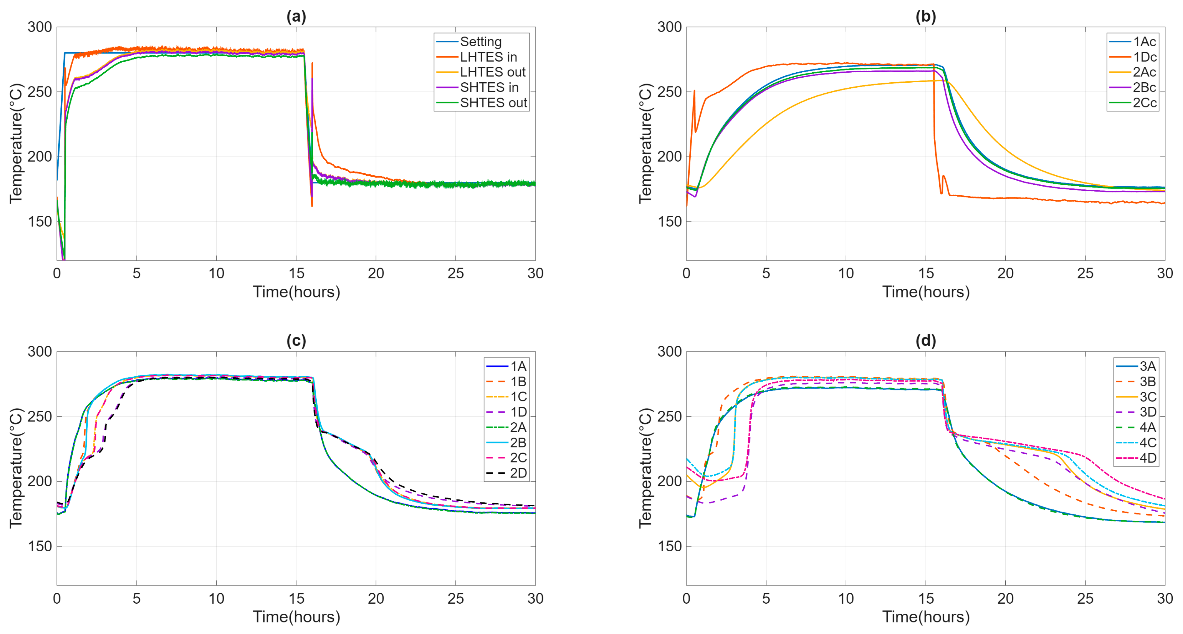
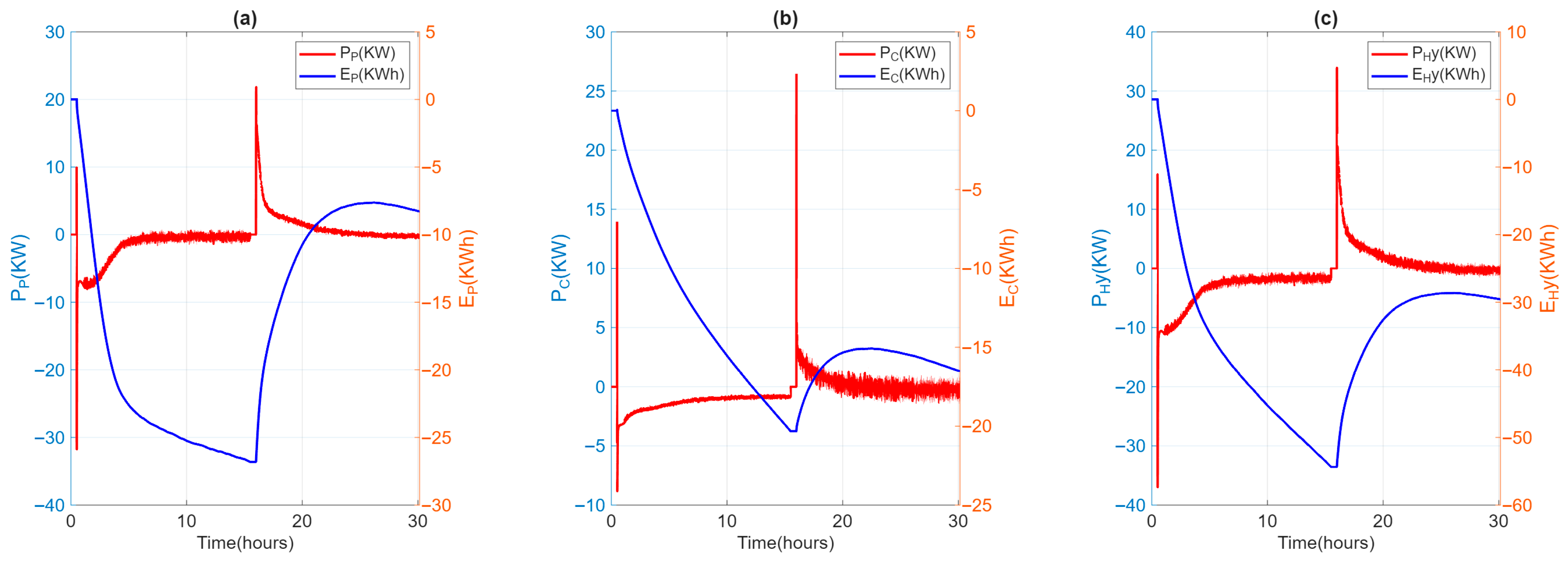
During the test, the ambient temperature remained stable between 20 and 25 °C. The casing temperature of the individual TES units was around 37 °C, which was in line with the project’s specifications. The temperature and flow rate inlet to HyTES were kept constant and equal to the test specification values. The velocity of the heat transfer fluid is about 1.5 m/s in the SH02 and 0.5 m/s in the LHTES, implying turbulent heat transfer everywhere. Figure 7 shows the temperature trends of the HTF entering and exiting HyTES and the individual units of the internal and external temperatures at SH02 and LH02. Given the input and output temperatures of the HTF from HyTES and from the individual units, it is then possible to derive the relative power curves (Figure 8). The power will then be negative during the charging phase (heat transferred to the TES) and positive during the discharge phase (heat recovered from the TES). The calculated powers include both the heat transmitted to the TES and the heat lost by it. Once the thermal losses have been assessed, it is possible to calculate the share of heat retained by the TES or released by it.
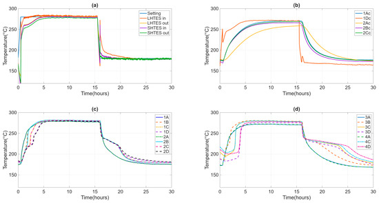
Figure 7.
Evolution of the inlet and outlet temperature of HTF from HyTES and constituent systems (a), of the internal temperatures at SH02 (b) and LH02 (c), and the external temperatures at LH02 (d).
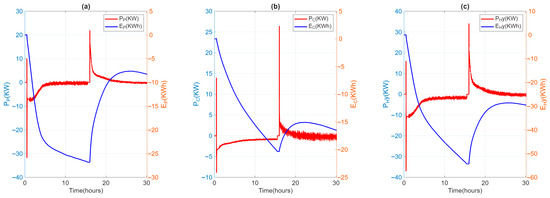
Figure 8.
Power (P) and absorbed/released energy evolution (E) for LH02 (a) and SH02 (b) and HyTES (c) units.
4.2. Thermal Losses
Upon the HyTES system reaching a steady state at the conclusion of its charging (280 °C) and discharging (180 °C) phases, the power supplied to the system and its components is assumed to precisely compensate for thermal losses, as documented in Table 3, where thermal losses at the maximum and minimum operating temperatures are reported. In the hypothesis that these losses vary linearly with temperature, it is possible to extrapolate the contribution of thermal losses at any operating temperature and, therefore, to evaluate the amount of energy actually stored in HyTES and in the various elements.

Table 3.
Performance indexes of HyTES and constituent units.
4.3. Evaluation of KPIs
By processing data obtained from the charging/discharging test to determine the power curve of the HyTES system, it is possible to derive a series of “performance indicators” (PIs) to define the main characteristics of the system. From these indices, it is then appropriate to extract the most important and generic ones, making them “key performance indicators” (KPIs).
The storage capacity of the HyTES system under theoretical conditions is calculated as the sum of the storage capacity of the following: the thermal storage medium, heat transfer fluid, integrated heat exchangers, PCM container, and thermal insulation. As THTF,max = 280 °C and THTF,min = 180 °C, it has been assessed to have a theoretical capacity of 38.7 kWh (Table 2).
Thermal insulation has been considered because it represents a significant share of the storage capacity (about 47% in the case of concrete TES). TES with PCM contributes 70% of HyTES storage, with latent heat accounting for 44%. The TES in concrete also shows a small contribution of latent heat (8%), while the stored heat is divided into almost equal parts between the concrete (52%) and the insulation (48%). The remaining performance indices were calculated, as shown above, and reported in Table 3.
4.4. Partial Consecutive Charging/Discharging Test
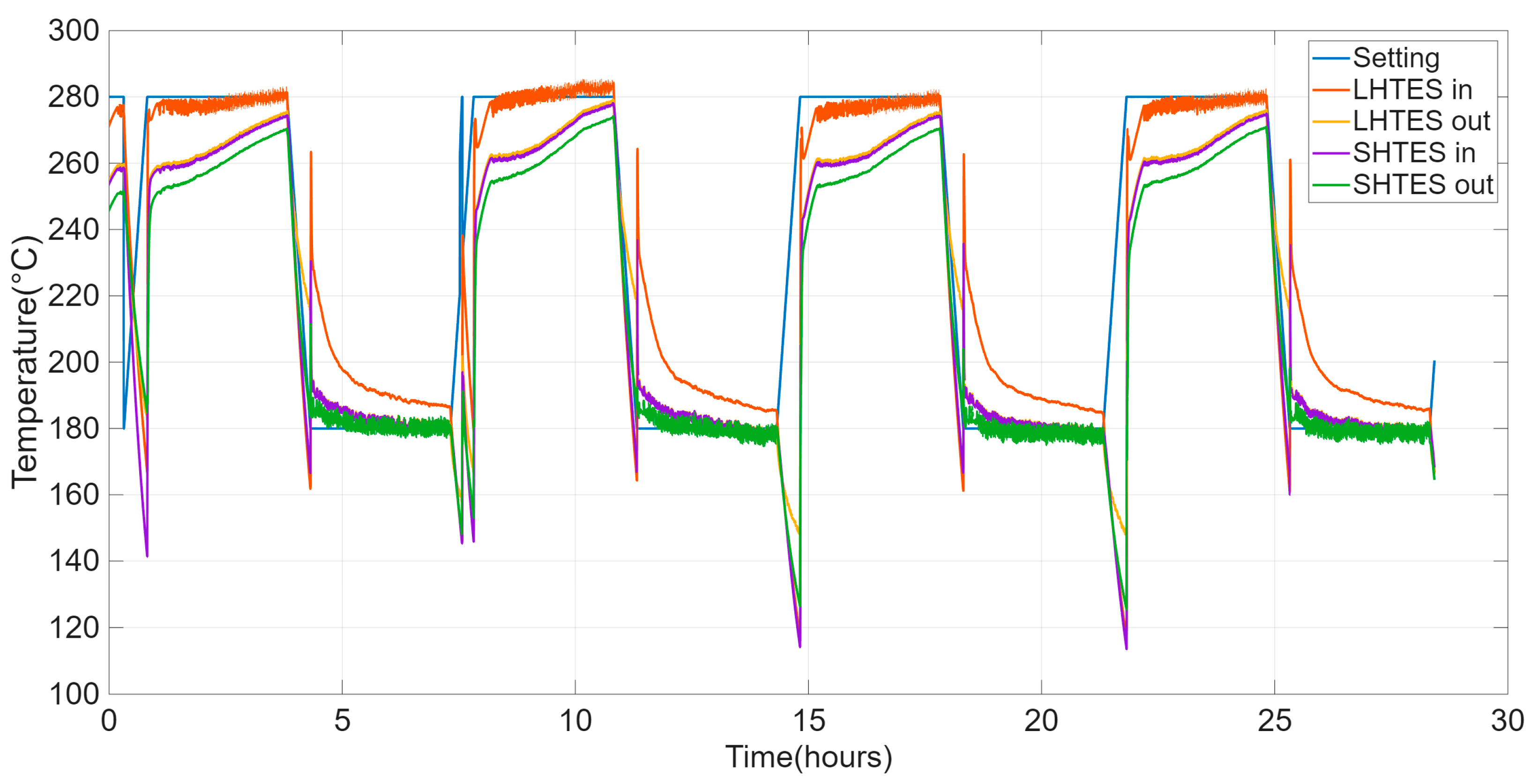
The main results of the HyTES test, to evaluate its thermal behavior following different charging/discharging cycles, are shown below. As specified, four consecutive charging/discharging cycles were carried out in the operating range of 180–280 °C, with reduced charging and discharging durations compared to the previous single cycle.
The primary goal of this test is not to assess the material’s durability or the long-term reproducibility of its behavior. Instead, it is to observe the system’s performance during the initial cycles. This test, indeed, serves to verify the system’s first stabilization, with particular attention to the comparison between the initial cycles. Figure 9 shows the trends of the inlet and outlet temperatures of HTF in HyTES and its components.
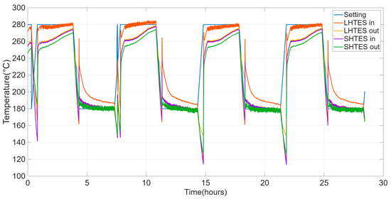
Figure 9.
Evolution of the HTF setting and inlet and outlet temperatures from the SHTES and LHTES units for the cyclic test on the HyTES system.
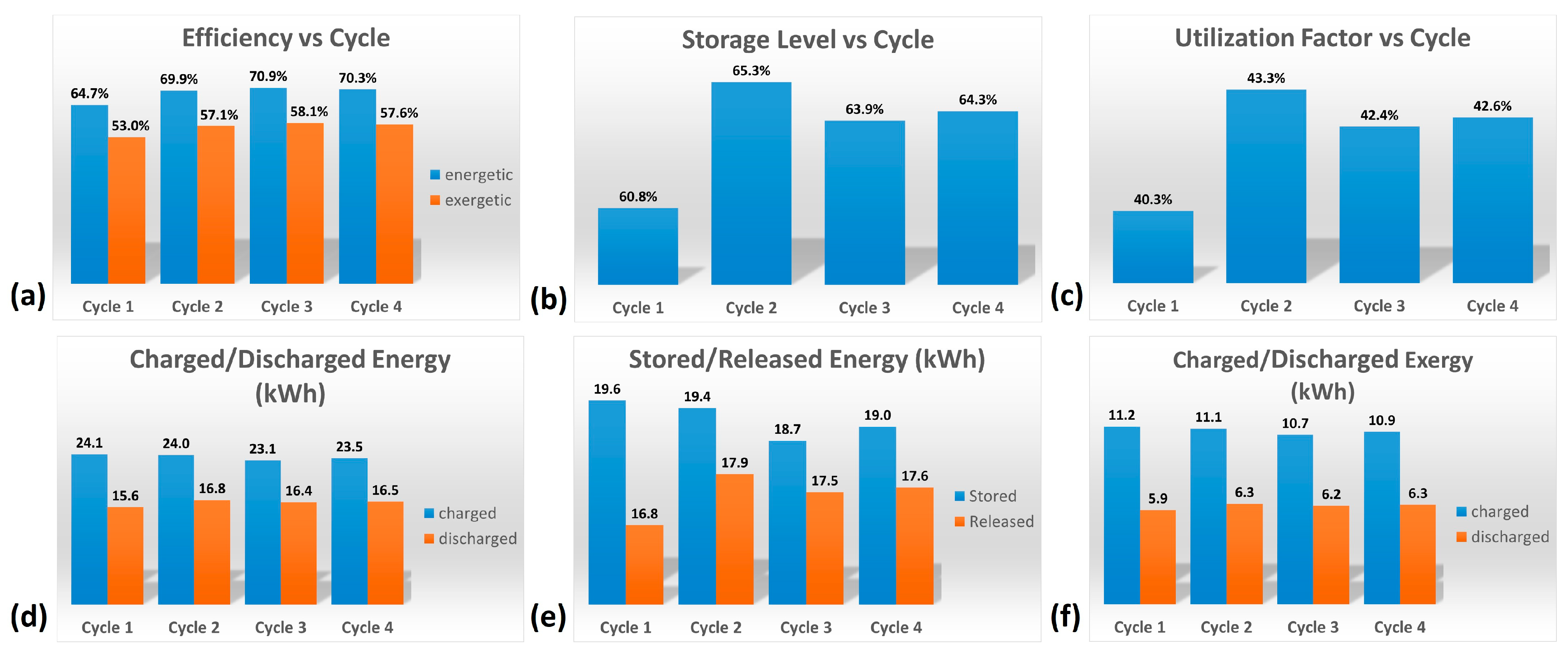
The various factors characterizing the HyTES system in these new conditions were then calculated. Figure 10 and Table 4 show the main results obtained by the partial consecutive charging/discharging test on the HyTES system. Specifically, the trend of these properties is observed to be oscillating, and it tends to dampen as the cycling continues; a stable profile is only obtained after the first two charging/discharging cycles. Based on the imposed operating conditions, the thermal behavior of the HyTES can be summarized as follows:
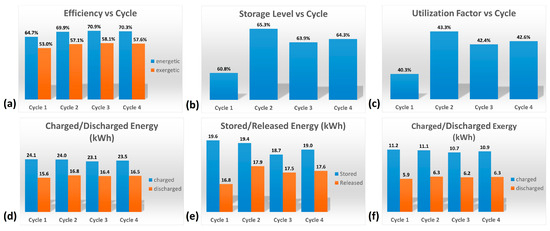
Figure 10.
Histograms of the main results obtained from the cyclic test on HyTES system: (a) Efficiency vs. Cycle; (b) Storage Level vs. Cycle; (c) Utilization Factor vs. Cycle; (d) Charged/Discharged Energy; (e) Stored/Released Energy; (f) Charged/Discharged Exergy.

Table 4.
Main results obtained by cyclic test on HyTES system.
- The system shows a thermal efficiency of about 70%, due to the present thermal losses;
- Its exergetic efficiency, on the other hand, is about 58%, due to the higher quantity of heat charged at a high temperature compared to the lower one discharged at a lower temperature;
- The storage level is 64% and the utilization factor is 43%: these values are quite low because the duration of the cycle is too limited and, consequently, the energy discharged is much lower than both the ideally downloadable energy (cycle at 100%) and the theoretical one, respectively;
- The energy charged in Hytes is about 23.5 kWh, while the discharged one is 16.5 kWh;
- The energy stored in HyTES is about 19 kWh and the released energy is 17.6 kWh;
- The charged exergy is equal to 10.9 kWh and the discharged exergy is 6.3 kWh.
4.5. Discussion
Overall, the illustrated experimental tests have shown that, for the HyTES system, the sensible heat section, while providing a substantial contribution in terms of stored heat, could be improved. To enhance its performance, it would be necessary to increase its thermal capacity, or to use not just one but several concrete elements connected in series and parallel. This way, the thermal losses (exposed surface) can be lower in relation to the thermal capacity (volume) of the SHTES subsystem.
After a few rounds of cyclic testing on HyTES, it was observed that it takes at least three to four full charge–discharge cycles to achieve stable thermal behavior. To achieve a performance closer to the maximum, you need to extend the charging and discharging times beyond what was used in the current tests. In this regard, the study by Becattini et al. similarly underscored the need for multiple charge/discharge cycles to stabilize a system’s thermal behavior over time, a process that can, however, lead to diminished performance [54]. In fact, they state that, in their experience, the presented results indicate a decrease in the performance of the TES at each cycle, attributing it to four factors: thermal losses, mass flow rates measured experimentally lower than those designed, average mass flow rates measured during the discharge phases that are lower than the charge phases, and the inflow temperature of the heat transfer fluid not being constant during charging. The effect of these factors, and especially of thermal losses, can also be present in the current experimentation, and may include the capacitive contribution of insulation. This contribution becomes important in a system with low storage capacity, such as the SHTES of HyTES. Despite the reduction in its performance, the HyTES system maintains the positive characteristics of an LHTES system, such as a high density of stored energy, compactness, and stabilization of the output temperature during the discharge phase, with a substantial contribution from the SHTES system in terms of increasing overall capacity, energy recovery, and, therefore, cost containment.
The main results, which include the performance indicators, are summarized in Table 5. It is worth noting that exergy efficiency penalizes charging at a higher temperature compared to discharging at a lower temperature, and is therefore naturally lower than energy efficiency. This is an important aspect to consider when heat quality is relevant (e.g., for the CSP assessment).

Table 5.
Main performance indicators (PI) of the HyTES system.
From an economic perspective, it must be noted that determining a definitive cost for a CSLHTES system is extremely challenging, as it is contingent upon numerous factors, encompassing both technical specifications and application requirements.
Some of these factors are as follows:
- The size factor (capacity): Larger systems (e.g., for industrial or solar power plants) benefit from economies of scale. In fact, costs are often expressed in €/kWh of storage capacity;
- The operating temperature: Systems that operate at higher temperatures (e.g., for industrial or CSP applications) require more expensive materials (both for PCMs and for containers/heat exchangers) and better-performing thermal insulation;
- PCMs: These are the key element of latent storage and they have a higher cost than materials for sensible storage (such as water, rock, or gravel). The cost varies according to the type of PCM (paraffins, hydrated salts, eutectics) and their purity;
- System design (heat exchangers): Efficient integration of PCMs into a system (e.g., through encapsulation or finned heat exchangers) is complex and costly, as PCMs generally have low thermal conductivity. The need for sophisticated heat exchangers (tubes, fins) has a significant impact;
- Specific application: A low-temperature system will have a different cost and complexity than a large industrial storage system (high temperature) or a passive integrated system.
However, the TES systems illustrated here have estimated individual costs, for low and medium production prototypes, of about 80 €/kWh for the LHTES system and 60 €/kWh for the SHTES system. The cost of a CSLHTES system will then be determined, since the two technologies are separate, by the proportion between them, or by the type of performance required and the application considered. Of course, future large systems are expected to have reduced costs due to the benefits of economies of scale.
5. Conclusions
Thermal energy storage holds a fundamental significance in the industrial sector by allowing companies to overcome the temporal misalignment between heat demand and the availability of the heat source. This is fundamental for increasing the efficiency of industrial production and for promoting the use of renewable energy sources, such as solar energy. Among the various available TES solutions (sensible, latent, or thermochemical), the combined sensible/latent heat TES (CSLHTES) solution is attracting more attention because it exhibits several “ideal” characteristics inherited from the single sensible or latent heat storage technologies: high energy storage density, compactness, high efficiency, stable supplied heat temperature, and good power output. The aim of the present work is to experimentally characterize the thermal behavior of a CSLHTES system and to evaluate its potential improvements. This system, HyTES, consists of two thermal storage units connected in series: one with sensible heat (ENEA-TES-SH02) and one with latent heat (ENEA-TES-LH02). It operates in a temperature range between 180 °C and 280 °C to meet the requirements of typical industrial applications (such as CSP plants, process heat, district heating/cooling, and desalination). The experimental characterization was accompanied by the preparation of a test procedure, which was designed to be as rigorous as possible, based on existing documents and regulations. This procedure aims to determine the main key performance indicators (KPIs) (Table 5), which are essential elements for comparing different types of systems.
This was essential because so far, there are no standardized test procedures. The results obtained for HyTES lead to the following conclusions:
- In the absence of dedicated standards, an appropriate test procedure was developed, based on some limited new standards (IEC TS 62862-2-1:2021) and works of international groups such as the partners of the SFERA-III project;
- The combined system suggests, as assumed, a general improvement in performance compared to the individual units. Its thermal behavior is driven by the performance of the LHTES unit, given its higher thermal capacity, but the SHTES unit still contributes, to increase overall capacity, energy recovery, and, therefore, cost-effectiveness;
- Although the sensible heat section contributes significantly to the stored thermal energy, its efficiency is diminished by substantial thermal losses and the predominant influence of thermal insulation;
- To improve the SHTES unit performance, an increase in its thermal capacity, using not one but several concrete elements connected in series and parallel, and an accurate sizing of the insulation are necessary. This way, thermal losses are lower in relation to the thermal capacity of the SHTES subsystem.
- The cyclic tests have shown that more than four complete charging/discharging cycles are necessary to stabilize the thermal behavior of the system;
- In the cyclic test, charging and discharging times longer than those adopted should be carried out to increase the performance of the system;
- Some performance indicators are obtained for the HyTES system. They characterize this CSHTES in the current configuration and it should be compared with its future evolutions.
Most papers in the literature concern the use of integrated CSLHTES systems (a single container for both technologies), where latent heat is only a modest fraction of the total thermal capacity, as it is responsible for stabilizing the outlet temperatures of the HTF during the exhaust phase.
A comparison with the literature articles often indicates integrated designs and a smaller share of latent capacity. A comparison between them shows that a reduced-scale hybrid sensible/latent heat accumulator (e.g., characterized by a nominal volume of 48.6 dm3 at 80 °C, comprising an aqueous medium, hosting macro-encapsulated phase change materials (PCMs)) can reach efficiencies up to 58%. Meanwhile, in larger hybrid systems, 70% has been achieved.
Higher efficiencies have been obtained with hybrid thermocline-type systems, featuring encapsulated PCMs, or with cascaded PCMs configurations of three to five stages.
In any case, the most encountered problem with PCMs is their low thermal conductivity; consequently, low-cost sensible natural stones are used to improve the heat transfer of the PCM. Stone packing height is another factor that influences storage performance, and therefore different filling heights can be analyzed.
Thermocline thermal energy storage, which can use molten salt as a heat transfer fluid (HTF), may present a drawback when integrated with CSP (concentrated solar power), due to its low capacity and utilization ratio, resulting from fluctuations in solar energy availability or alterations in electrical demand. However, some results show that the combined sensible-latent heat storage scenario yields the highest capacity ratio.
In some cases, in fact, excellent energy density and efficiencies have been obtained by PCM–graphite–PCM, where high temperature is required. In fact, by integrating PCMs with graphite in a sandwich design, the storage efficacy of the graphite system was enhanced from 59.0%, in the sole graphite configuration, to 80.2%, in the hybrid system. In addition, PCM in cascade can also be a good alternative to these systems, providing up to 57% efficiency and 91 kWh/ton of energy density if molten metal alloys are considered to be PCMs. Nevertheless, some of the literature’s findings suggest that an augmented quantity of phase change materials (PCMs) is required to facilitate an efficacious cascaded thermal energy storage (TES) system, should the thermal input (temperature) of the hot heat transfer fluid (HTF) be diminished.
The evaluation and comparative assessment presented herein were predicated on the thermodynamic efficacy of the TES configuration. Given judicious engineering specifications, all investigated TES architectures are capable of satisfying the predetermined operational criteria. To ascertain an optimal configuration, a subsequent economic viability study is warranted, utilizing the thermodynamic performance metrics derived from this research. This financial assessment should ideally be executed at the concentrated solar power (CSP) plant scale, given that modifications within the TES subsystem may potentially impact the operational parameters of the solar receiver, heat exchange apparatus, and the power generation cycle.
Finally, beyond the disadvantage of having to manage the greatest heat losses, adopting a solution that keeps the two technologies separate can have numerous advantages:
- It allows for the optimization of heat exchange, and the related surfaces, as a function of the adopted technology;
- It facilitates the design of individual SHTES and LHTES systems;
- It allows for rapid maintenance of individual systems;
- It allows great flexibility in the sizing of CSLHTES systems of various capacities and compositions.
Also, the proportion between the capacity of the SHTES system and that of the LHTES system must also be studied according to the kind of application, taking into account the ability of the PCM to stabilize the output temperatures of the HTF. In fact, the latent heat unit may offer a higher capacity than the other unit. This is especially true for systems that require high compactness and stored energy density, provided the costs of a pure LHTES system remain limited. The heat-sensible unit holds a good thermal storage capacity but guarantees greater cost-effectiveness. The current experimental work on a simple combined sensible/latent storage system can be used to validate simplified models to be developed, aimed at analyzing the thermal behavior of these systems and optimizing their size and the best proportion between sensible and latent technologies, which also depends on the type of application.
In conclusion, this approach should be further analyzed and deepened, not only from an energy and exergetic point of view, but also from an economic and environmental impact one. Subsequently, it would be necessary to move on to experimental tests with larger CSLHTES systems to verify their performance and evaluate their main KPIs.
Author Contributions
Conceptualization, R.L. and A.M.; methodology, A.M. and D.N.; validation, D.N.; formal analysis, A.M.; investigation, R.L.; data curation, G.G. and G.N.; writing—original draft preparation, R.L., D.N. and A.M.; writing—review and editing, R.L., D.N. and A.M.; funding acquisition, R.L. All authors have read and agreed to the published version of the manuscript.
Funding
This research was funded by MASE, the Italian Ministry of Environment and Energy Security, by means of the Research on Electric System fund—PTR 2025-27—Project 1.2: Electrochemical and thermal storage technologies, within Work Package 4—Thermal Storage: materials and innovative systems.
Data Availability Statement
The data presented in this study are available upon request from the corresponding author, as they are not publicly available due to privacy concerns.
Conflicts of Interest
The authors declare no conflicts of interest.
Abbreviations
The following abbreviations are used in this manuscript:
| Cp | Heat capacity at constant pressure [J/(kg °C)] |
| CSLHTES | Combined sensible/latent heat TES |
| CSP | Concentrating solar power |
| Cth | Theoretical storage capacity [J] |
| ∆T | Temperature difference [°C] |
| FU | Utilization factor |
| HDPE | High-density polyethylene |
| HSM | Heat storage medium |
| HTF | Heat transfer fluid |
| HyTES | Hybrid thermal energy storage |
| KPI | Key performance indicator |
| LH | Latent heat |
| LHTES | Latent heat thermal energy storage |
| mEPCM | Micro-encapsulated phase change material |
| M | Mass [kg] |
| Mass flow [kg/s] | |
| P | Power [W] |
| PCM | Phase change materials |
| PIs | Performance indexes |
| Q | Thermal energy [J] |
| Qsto_char | Stored energy in charging phase [J] |
| Qsto_disc | Stored energy in discharging phase [J] |
| SC | Storage capacity [J] |
| SFERA-III | Solar Facilities for the European Research Area III |
| SH | Sensible heat |
| SHTES | Sensible heat thermal energy storage |
| SP | System parameters |
| SS-PCM | Shape-stabilized phase change materials |
| TES | Thermal energy storage |
| T | Temperature [°C] |
| Tm | Average temperature [°C] |
| u | Uncertainty |
| w | Flow [m/s] |
| ξ | Time integration variable |
| Exergy [J] | |
| ηTES | Energy storage efficiency |
| ηex | Exergy storage efficiency |
| Subscripts | |
| amb | Environment |
| char | Charge |
| coib | Thermal insulator |
| disc | Discharge |
| in | Inlet |
| max | Maximum |
| min | Minimum |
| out | Outlet |
References
- Rahman, M.; Olufemi Oni, A.; Gemechu, E.; Kumar, A. Assessment of energy storage technologies: A review. Energy Convers. Manag. 2020, 223, 113295. [Google Scholar] [CrossRef]
- IEA. World Energy Outlook 2023. 2023. Available online: https://www.iea.org/reports/world-energy-outlook-2023 (accessed on 1 November 2025).
- Leonard, M.D.; Michaelides, E.E.; Michaelides, D.N. Energy storage needs for the substitution of fossil fuel power plants with renewables. Renew. Energy 2020, 145, 951–962. [Google Scholar] [CrossRef]
- Arce, P.; Medrano, M.; Gil, A.; Oró, E.; Cabeza, L.F. Overview of thermal energy storage (TES) potential energy savings and climate change mitigation in Spain and Europe. Appl. Energy 2015, 88, 2764–2774. [Google Scholar] [CrossRef]
- Cabeza, L.F.; Miró, L.; Oró, E.; de Garcia, A.; Martin, V.; Kronauer, A. CO2 mitigation accounting for thermal energy storage (TES) case studies. Appl. Energy 2015, 155, 365–377. [Google Scholar] [CrossRef]
- Cabeza, L.F. Chapter 2-Advances in thermal energy storage systems: Methods and applications. In Advances in Thermal Energy Storage Systems, 2nd ed.; Cabeza, L.F., Ed.; Woodhead Publishing Series in Energy; Woodhead Publishing: Cambridge, UK, 2021; pp. 37–54. [Google Scholar] [CrossRef]
- Arteconi, A.; Hewitt, N.J.; Polonara, F. State of the art of thermal storage for demand-side management. Appl. Energy 2012, 93, 371–389. [Google Scholar] [CrossRef]
- González-Portillo, L.F.; Muñoz-Antón, J.; Martínez-Val, J.M. An analytical optimization of thermal energy storage for electricity cost reduction in solar thermal electric plants. Appl. Energy 2017, 185, 531–546. [Google Scholar] [CrossRef]
- Jacob, R.; Belusko, M.; Fernández, A.I.; Cabeza, L.F.; Samana, W.; Bruno, F. Embodied energy and cost of high temperature thermal energy storage systems for use with concentrated solar power plants. Appl. Energy 2016, 180, 586–597. [Google Scholar] [CrossRef]
- Wagner, S.J.; Rubin, E.S. Economic implications of thermal energy storage for concentrated solar thermal power. Renew. Energy 2014, 61, 81–95. [Google Scholar] [CrossRef]
- Kuravi, S.; Trahan, J.; Goswami, D.Y.; Rahman, M.M.; Stefanakos, E.K. Thermal energy storage technologies and systems for concentrating solar power plants. Prog. Energy Combust. Sci. 2013, 39, 285–319. [Google Scholar] [CrossRef]
- Liu, M.; Tay, N.H.S.; Bell, S.; Belusko, M.; Jacob, R.; Will, G.; Saman, W.; Bruno, F. Review on concentrating solar power plants and new developments in high temperature thermal energy storage technologies, Renew. Sustain. Energy Rev. 2016, 53, 1411–1432. [Google Scholar]
- Miró, L.; Gasia, J.; Cabeza, L.F. Thermal energy storage (TES) for industrial waste heat (IWH) recovery: A review. Appl. Energy 2016, 179, 284–301. [Google Scholar] [CrossRef]
- Renaldi, R.; Kiprakis, A.; Friedrich, D. An optimisation framework for thermal energy storage integration in a residential heat pump heating system. Appl. Energy 2017, 186, 520–529. [Google Scholar] [CrossRef]
- Alimohammadisagvand, B.; Jokisalo, J.; Kilpeläinen, S.; Ali, M.; Sirén, K. Cost-optimal thermal energy storage system for a residential building with heat pump heating and demand response control. Appl. Energy 2016, 174, 275–287. [Google Scholar] [CrossRef]
- Cabeza, L.F.; de Gracia, A.; Zsembinszki, G.; Borri, E. Perspectives on thermal energy storage research. Energy 2021, 231, 120943. [Google Scholar] [CrossRef]
- Beck, A.; Sevault, A.; Drexler-Schmid, G.; Schöny, M.; Kauko, H. Optimal Selection of Thermal Energy Storage Technology for Fossil-Free Steam Production in the Processing Industry. Appl. Sci. 2021, 11, 1063. [Google Scholar] [CrossRef]
- Alva, G.; Lin, Y.; Fang, G. An overview of thermal energy storage systems. Energy 2018, 144, 341–378. [Google Scholar] [CrossRef]
- Therkelsen, P.; McKane, A. Implementation and rejection of industrial steam system energy efficiency measures. Energy Policy 2013, 57, 318–328. [Google Scholar] [CrossRef]
- Rathgeber, C.; Lävemann, E.; Hauer, A. Economic top–down evaluation of the costs of energy storages—A simple economic truth in two equations. J. Energy Storage 2015, 2, 436. [Google Scholar] [CrossRef]
- Halmschlager, D.; Beck, A.; Knöttner, S.; Koller, M.; Hofmann, R. Combined optimization for retrofitting of heat recovery and thermal energy supply in industrial systems. Appl. Energy 2022, 305, 117820. [Google Scholar] [CrossRef]
- Alva, G.; Liu, L.; Huang, X.; Fang, G. Thermal energy storage materials and systems for solar energy applications. Renew. Sustain. Energy Rev. 2017, 68, 693–706. [Google Scholar] [CrossRef]
- Paul, A.; Holy, F.; Textor, M.; Lechner, S. High temperature sensible thermal energy storage as a crucial element of Carnot Batteries: Overall classification and technical review based on parameters and key figures. J. Energy Storage 2022, 56, 106015. [Google Scholar] [CrossRef]
- Ibrahim, N.I.; Al-Sulaiman, F.A.; Rahman, S.; Yilbas, B.S.; Sahin, A.Z. Heat transfer enhancement of phase change materials for thermal energy storage applications: A critical review. Renew. Sustain. Energy Rev. 2017, 74, 26–50. [Google Scholar] [CrossRef]
- Mehling, H.; Cabeza, L.F. Heat and Cold Storage with PCM; Springer: Berlin/Heidelberg, Germany, 2008. [Google Scholar] [CrossRef]
- Dincer, I.; Rosen, M. Thermal Energy Storage: Systems and Applications; John Wiley & Sons: Hoboken, NJ, USA, 2002; Available online: https://books.google.at/books?id=EsfcWE5lX40C (accessed on 1 November 2025).
- Bista, S.; Hosseini, S.E.; Owens, E.; Phillips, G. Performance improvement and energy consumption reduction in refrigeration systems using phase change material (PCM). Appl. Therm. Eng. 2018, 142, 723–735. [Google Scholar] [CrossRef]
- Zalba, B.; Marín, J.M.; Cabeza, L.F.; Mehling, H. Review on thermal energy storage with phase change: Materials, heat transfer analysis and applications. Appl. Therm. Eng. 2003, 23, 251–283. [Google Scholar] [CrossRef]
- Nguyen, T.T.; Martin, V.; Malmquist, A.; Silva, C.A. A review on technology maturity of small scale energy storage technologies. Renew. Energy Env. Sustain. 2017, 2, 36. [Google Scholar] [CrossRef]
- Cabeza, L.F.; Martorell, I.; Miró, L.; Fernández, A.I.; Barreneche, C.; Cabeza, L.F.; Fernández, A.I.; Barreneche, C. Introduction to thermal energy storage systems; Chapter 1. In Advances in Thermal Energy Storage Systems, 2nd ed.; Cabeza, L.F., Ed.; Woodhead Publishing Series in Energy; Woodhead Publishing: Cambridge, UK, 2021; pp. 1–33. [Google Scholar] [CrossRef]
- Merlin, K.; Delaunay, D.; Soto, J.; Traonvouez, L. Heat transfer enhancement in latent heat thermal storage systems: Comparative study of different solutions and thermal contact investigation between the exchanger and the PCM. Appl. Energy 2016, 166, 107–116. [Google Scholar] [CrossRef]
- Yang, X.; Lu, Z.; Bai, Q.; Zhang, Q.; Jin, L.; Yan, J. Thermal performance of a shell-and-tube latent heat thermal energy storage unit: Role of annular fins. Appl. Energy 2017, 202, 558–570. [Google Scholar] [CrossRef]
- Augspurger, M.; Choi, K.; Udaykumar, H. Optimizing fin design for a PCM based thermal storage device using dynamic kriging. Int. J. Heat Mass Transfer 2018, 121, 290–308. [Google Scholar] [CrossRef]
- Muhammad, M.; Badr, O. Performance of a finned, latent-heat storage system for high temperature applications. Appl. Therm Eng. 2017, 116, 799–810. [Google Scholar] [CrossRef]
- Mesalhy, O.; Lafdi, K.; Elgafy, A.; Bowman, K. Numerical study for enhancing the thermal conductivity of phase change material (PCM) storage using high thermal conductivity porous matrix. Energy Convers Manag. 2005, 46, 847–867. [Google Scholar] [CrossRef]
- Chieruzzi, M.; Miliozzi, A.; Crescenzi, T.; Kenny, J.M.; Torre, L. Synthesis and Characterization of Nanofluids Useful in Concentrated Solar Power Plants Produced by New Mixing Methodologies for Large-Scale Production. J. Heat Transf. 2018, 140, 42401. [Google Scholar] [CrossRef]
- Chieruzzi, M.; Cerritelli, G.F.; Miliozzi, A.; Kenny, J.M.; Torre, L. Heat capacity of nanofluids for solar energy storage produced by dispersing oxide nanoparticles in nitrate salt mixture directly at high temperature. Sol. Energy Mater. Sol. Cells 2017, 167, 60–69. [Google Scholar] [CrossRef]
- Elfeky, K.E.; Mohammed, A.G.; Wang, Q. Thermal Performance Evaluation of Combined Sensible-Latent Heat Storage Tank with a Different Storage Medium. Chem. Eng. Trans. 2022, 94, 1267–1272. [Google Scholar] [CrossRef]
- Ahmed, N.; Elfeky, K.E.; Lu, L.; Wang, Q.W. Thermal and economic evaluation of thermocline combined sensible-latent heat thermal energy storage system for medium temperature applications. Energy Convers. Manag. 2019, 189, 14–23. [Google Scholar] [CrossRef]
- Rahman, K.H.U.; Rahman, M.M. A review of temperature combined sensible/latent heat storage systems. In Proceedings of the 191st IIER International Conference, Tokyo, Japan, 26–27 September 2018. [Google Scholar]
- Geissbühler, L.; Kolman, M.; Zanganeh, G.; Haselbacher, A.; Steinfeld, A. Analysis of industrial-scale high-temperature combined sensible/latent thermal energy storage. Appl. Therm. Eng. 2016, 101, 657–668. [Google Scholar] [CrossRef]
- Frazzica, A.; Manzan, M.; Sapienza, A.; Freni, A.; Toniato, G.; Restuccia, G. Experimental testing of a hybrid sensible-latent heat storage system for domestic hot water applications. Appl. Energy 2016, 183, 1157–1167. [Google Scholar] [CrossRef]
- Frazzica, A.; Manzan, M.; Palomba, V.; Brancato, V.; Freni, A.; Pezzi, A.; Vaglieco, B.M. Experimental Validation and Numerical Simulation of a Hybrid Sensible-Latent Thermal Energy Storage for Hot Water Provision on Ships. Energies 2022, 15, 2596. [Google Scholar] [CrossRef]
- Zauner, C.; Hengstberger, F.; Mörzinger, B.; Hofmann, R.; Walter, H. Experimental characterization and simulation of a hybrid sensible-latent heat storage. Appl. Energy 2017, 189, 506–519. [Google Scholar] [CrossRef]
- Liu, M.; Riahi, S.; Jacob, R.; Belusko, M.; Bruno, F. Design of sensible and latent heat thermal energy storage systems for concentrated solar power plants: Thermal performance analysis. Renew. Energy 2020, 151, 1286–1297. [Google Scholar] [CrossRef]
- Zhang, S.; Li, Y.; Yan, Y. Hybrid sensible-latent heat thermal energy storage using natural stones to enhance heat transfer: Energy, exergy, and economic analysis. Energy 2024, 286, 129530. [Google Scholar] [CrossRef]
- Ahmed, N.; Elfeky, K.E.; Qaisrani, M.A.; Wang, Q.W. Numerical characterization of thermocline behavior of combined sensible-latent heat storage tank using brick manganese rod structure impregnated with PCM capsules. Sol. Energy 2019, 180, 243–256. [Google Scholar] [CrossRef]
- Nallusamy, N.; Velraj, R. Numerical and Experimental Investigation on a Combined Sensible and Latent Heat Storage Unit Integrated with Solar Water Heating System. J. Sol. Energy Eng. ASME 2009, 131, 041002. [Google Scholar] [CrossRef]
- Elfeky, K.E.; Mohammed, A.G.; Ahmed, N.; Wang, Q. Thermal performance of cascaded and combined sensible-latent heat storage tank under fluctuations in sunlight and electric demand. Appl. Therm. Eng. 2023, 229, 120575. [Google Scholar] [CrossRef]
- Zahid, M.S.; Ahmed, N.; Qaisrani, M.A.; Mahmood, M.; Ali, M.; Waqas, A.; Assadi, M. Charging and discharging characterization of a novel combined sensible-latent heat thermal energy storage system by experimental investigations for medium temperature applications. J. Energy Storage 2022, 55, 105612. [Google Scholar] [CrossRef]
- Ahmed, N.; Elfeky, K.E.; Lu, L.; Wang, Q.W. Thermal performance analysis of thermocline combined sensible-latent heat storage system using cascaded-layered PCM designs for medium temperature applications. Renew. Energy 2020, 152, 684–697. [Google Scholar] [CrossRef]
- Becattini, V.; Haselbacher, A. Toward a new method for the design of combined sensible/latent thermal energy storage using non-dimensional analysis. Appl. Energy 2019, 247, 322–334. [Google Scholar] [CrossRef]
- Kasper, L.; Pernsteiner, D.; Schirrer, A.; Jakubek, S.; Hofmann, R. Experimental characterization, parameter identification and numerical sensitivity analysis of a novel hybrid sensible/latent thermal energy storage prototype for industrial retrofit applications. Appl. Energy 2023, 344, 121300. [Google Scholar] [CrossRef]
- Becattini, V.; Geissbühler, L.; Zanganeh, G.; Haselbacher, A.; Steinfeld, A. Pilot-scale demonstration of advanced adiabatic compressed air energy storage, Part 2: Tests with combined sensible/latent thermal-energy storage. J. Energy Storage 2018, 17, 140–152. [Google Scholar] [CrossRef]
- Laing, D.; Bauer, T.; Lehmann, D.; Bahl, C. Development of a Thermal Energy Storage System for Parabolic Trough Power Plants with Direct Steam Generation. J. Sol. Energy Eng. 2010, 132, 021011. [Google Scholar] [CrossRef]
- Stückle, A.; Laing, D.; Müller-Steinhagen, H. Numerical Simulation and Experimental Analysis of a Modular Storage System for Direct Steam Generation. Heat Transf. Eng. 2014, 35, 812–821. [Google Scholar] [CrossRef]
- Liberatore, R.; Nana, F.; Cardamone, S.; Passera, T.; Carnelli, L.; Russo, V.; Miliozzi, A.; Nicolini, D.; Petroni, G.; Gaggioli, W. JCA Eni ENEA Project: CSP & Thermal Storage. In Proceedings of the International Solar Paces Congress, Rome, Italy, 8–11 October 2024. in press on German National Library of Science and Technology (TIB), Hannover, Germany, 2025. [Google Scholar]
- IEC TS 62862-2-1:2021; Solar Thermal Electric Plants–Part 2-1: Thermal Energy Storage Systems–Characterization of Active, Sensible Systems for Direct and Indirect Configurations, Technical Specification, ICS 27.160. International Electrotechnical Commission: Geneva, Switzerland, 2021.
- Azevedo, P.; Canavarro, D.; Fluri, T.; Gaggioli, W.; Liberatore, R.; Garcia, P.; Georgiou, M.; Osório, T.; Rojas, E.; Tari, I.; et al. Protocol for Testing Sensible and Latent Storage Prototypes, SFERA-III Project (G.A. No. 823802). 2022. Available online: https://sfera3.sollab.eu/wp-content/uploads/2023/12/SFERA-III-D6.3-Protocol-for-testing-sensible-and-latent-storage-prototypes.pdf (accessed on 1 November 2025).
- Bauer, T.; Breidenbach, N. Overview of m f molten salt storage systems and material development for solar thermal power plants. In Proceedings of the World Renewable Energy Forum, WREF 2012, Denver, CO, USA, 13–17 May 2012; Volume 2, pp. 837–844. [Google Scholar]
- Chieruzzi, M.; Cerritelli, G.F.; Miliozzi, A.; Kenny, J.M. Effect of nanoparticles on heat capacity of nanofluids based on molten salts as PCM for thermal energy storage. Nanoscale Res. Lett. 2013, 8, 448. [Google Scholar] [CrossRef] [PubMed]
- Zavoico, A.B. Solar Power Tower Design Basis Document; Sandia National Laboratories Albuquerque: Albuquerque, NM, USA; Livermore, CA, USA, 2001. [Google Scholar]
- Miliozzi, A.; Dominici, F.; Candelori, M.; Veca, E.; Liberatore, R.; Nicolini, D.; Torre, L. Development and characterization of concrete/PCM/diatomite composites for thermal energy storage in CSP/CST applications. Energies 2021, 14, 4410. [Google Scholar] [CrossRef]
- Dominici, F.; Miliozzi, A.; Torre, L. Thermal Properties of Shape-Stabilized Phase Change Materials Based on Porous Supports for Thermal Energy Storage. Energies 2021, 14, 7151. [Google Scholar] [CrossRef]
- Therminol-66 Technical Bulletin. Available online: https://www.therminol.com/sites/therminol/files/documents/TF-8695_Therminol-66_Technical_Bulletin.pdf (accessed on 1 November 2025).
- Miliozzi, A.; Giannuzzi, G.M.; Mazzei, D.; Liberatore, R.; Crescenzi, T.; Mele, D. Dispositivo di Accumulo Termico, Sistema Modulare Incorporante il Dispositivo e Relativo Metodo di Realizzazione. ENEA Patent N. 860/2017, 15 November 2017. [Google Scholar]
- Measurement Good Practice Guide No. 11 (Issue 2). In A Beginner’s Guide to Uncertainty of Measurement; Bell, S., Ed.; Centre for Basic, Thermal and Length Metrology, National Physical Laboratory: London, UK, 1999; Issue 2 with amendments March 2001; ISSN 1368-6550. [Google Scholar]
- NASA-HDBK-8739.19-3; Measurement Uncertainty Analysis Principles and Methods. National Aeronautics and Space Administration: Washington, DC, USA, 2010.
- M3003: The Expression of Uncertainty and Confidence in Measurement, 1st ed.; UKAS Publication: Middlesex, UK, 1997.
- EA-4/02; Expression of the Uncertainty of Measurement in Calibration. European co-operation for Accreditation: Luxembourg, 1999.
- Adinberg, R.; Tamme, R.; Lange, D.; Py, X.; Rojas, E.; Fabrizi, F.; Hänchen, M. Report on the Methodology to Characterize Various Types of Thermal Storage Systems. Deliverable 2010, 15, 1. [Google Scholar]
- Rojas, E.; Bayón, R. Definition of Standardised Procedures for Testing Thermal Storage Prototypes for Concentrating Solar Thermal Plants; SFERA Project: Kuala Lumpur, Malaysia, 2011. [Google Scholar]
- Gschwander, S.; Lazaro, A.; Cabeza, L.F.; Günther, E.; Fois, M.; Chui, J. Development of a Test Standard for PCM and TCM Characterization. Part 1: Characterization of PCMs, IEA Solar Heating and Cooling/Energy Conservation through Energy Storage programme, Task 42/Annex 24, Report A2.1, working group A2 Test&Characterization; International Energy Agency (IEA): Paris, France, 2011. [Google Scholar]
Disclaimer/Publisher’s Note: The statements, opinions and data contained in all publications are solely those of the individual author(s) and contributor(s) and not of MDPI and/or the editor(s). MDPI and/or the editor(s) disclaim responsibility for any injury to people or property resulting from any ideas, methods, instructions or products referred to in the content. |
© 2025 by the authors. Licensee MDPI, Basel, Switzerland. This article is an open access article distributed under the terms and conditions of the Creative Commons Attribution (CC BY) license (https://creativecommons.org/licenses/by/4.0/).


