1. Introduction
In recent years, thermally activated building systems (TABS) have emerged as a promising concept for efficiently providing heating and cooling energy to buildings. The thermal mass of building components, such as ceilings and walls, is utilized to regulate room temperature by incorporating water-carrying pipes into these components. This not only enables uniform temperature control but also opens up the potential for shifting thermal loads—an increasingly important aspect, particularly in the context of renewable energies and fluctuating electricity generation [
1,
2].
A key feature of TABS is the high thermal mass and thus the ability of the component to store thermal energy over extended periods and release it with a time delay. This property can be exploited to shift energy consumption from periods of high demand to periods of surplus (‘load shifting’)—for instance, when using solar power or with a tariff-dependent electricity supply.
The majority of research into TABS to date has focused on conventional mineral building materials, such as concrete and masonry. Whilst these materials are ideal for thermal activation due to their high density, thermal conductivity and heat storage capacity, their carbon footprint is, compared to wood or similar bio-based materials, considerably larger [
3,
4]. With the increase in efficiency during the operational phase of the building and subsequent lower CO
2 emissions during the building’s use, the embodied energy of constructing the building becomes ever more important [
5,
6].
Romani et al. [
7] conducted a comprehensive literature review that classifies different types of construction of TABS, especially those with pipes embedded in ceilings or floors, and systematically describes different simulation methods, control strategies, and results from parametric studies. However, the focus is almost exclusively on concrete and masonry constructions.
In addition, Villar-Ramos et al. conducted a systematic literature review, with a particular focus on the potential of TABS to enhance thermal comfort and reduce final energy consumption. The studies published between 2015 and 2022 concentrated on the integration of TABS in various building components (roof, wall, floor, building envelope) and their combination with complementary technologies such as solar collectors, phase change materials or heat pumps. The findings indicate that the implementation of TABS technology can lead to a substantial reduction in indoor air temperature, with potential energy savings of up to 50% being realized [
8].
The energy performance of external walls has been improved by investigating wall structures with integrated pipe systems. Several studies have shown that integrating pipework into concrete walls can improve the insulation effect [
9,
10,
11,
12,
13]. Other studies have focused on concepts for shifting thermal energy within the building envelope. For example, solar heat gains can be transferred from south-facing façades to cooler north-facing façades [
14,
15,
16]. While these approaches demonstrate the potential of TABS beyond classic floor or ceiling systems, the materials used in these studies are all mineral-based [
17,
18,
19,
20,
21,
22,
23,
24,
25,
26].
In addition, the influence of different pipe geometries on thermal behavior was investigated. Studies show that capillary tube mats installed close to the surface have a faster reaction time, enable more homogeneous heat distribution, and can be operated at lower inlet temperatures [
27]. A further study compared six different panel types in order to identify the optimum combination of heat transfer performance and material efficiency in lightweight ceiling modules with capillary tubes [
28].
Another relevant aspect is the influence of the surface material. For instance, a study by Rodríguez Jara et al. [
29] demonstrates that, under certain climatic conditions, wood can attain surface temperatures comparable to granite, despite having significantly inferior thermal properties. These results are particularly important given the increasing demand for sustainable materials.
In response to growing ecological concerns related to CO
2-intense materials such as cement and concrete, bio-based building materials such as wood and bamboo are becoming increasingly popular. These materials are considered promising alternatives to concrete thanks to their high load-bearing capacity, lower carbon footprint, the potential for regional sourcing, and their relatively low environmental impact during production and disposal. However, from a thermal engineering perspective, they pose challenges as they generally have lower thermal conductivity and heat capacity. Some initial scientific research has already addressed this issue: for example, Bishara et al. [
30] experimentally investigated different types of heating pipe installation in wooden components and analyzed their effect on heat distribution. Heidenthaler et al. [
31] carried out numerical simulations comparing different types of wood, embedment depths and inlet temperatures with concrete references. The results show that, under certain boundary conditions, timber components can have a high thermal activation potential.
In addition to water-based systems, the transmission properties of alternative media have recently been investigated. In a study by Mindrup [
32], an air-based wall module with integrated microchannels was investigated. Activation takes place through a hot air flow, which could be of particular interest for lightweight construction systems but which poses other challenges in terms of control behavior, efficiency and comfort.
Despite these developments, research into bio-based materials for thermal component activation is still in its infancy. In particular, systematic comparisons of different types of wood and other bio-based materials, such as bamboo, under practical boundary conditions are lacking. The thermal storage potential of these materials in the context of load shifting and system inertia has not yet been adequately analyzed. Hybrid material approaches, which could combine ecological advantages with improved heat conduction, have also not yet been extensively analyzed.
This work aims to systematically investigate the thermal behavior of bio-based materials in component activation systems. Various influencing factors, including material selection, pipe spacing, embedding depth, inlet temperature and heat storage capacity, are analyzed using numerical simulations. The focus is on the potential for thermal load shifting, paying particular attention to the suitability of bio-based materials such as wood (e.g., spruce, pine, beech and oak) as well as bamboo.
The results will demonstrate, in an initially solely simulation-based step, the extent to which bio-based building materials can potentially substitute mineral-based components without significant thermal component activation efficiency losses. Additionally, this study will examine the functional advantages that hybrid material combinations offer over homogeneous materials.
2. Methodology
The following methodology was applied to systematically investigate the thermal behavior of the various materials and systems. In this initial analysis, the focus is on floor slabs, as ceilings are the most commonly used building components for thermally activated building systems [
7,
20]. Firstly, the slab structure is described, followed by an overview of the simulation tool and the parameters that were varied during the investigation. Finally, the assessment and evaluation parameters are presented in detail.
The thermal simulations were carried out using a parametric approach with the Delphin 6 software. Delphin is a hygrothermal simulation tool developed by the Chair of Building Climatology (IBK) at the Technical University of Dresden [
33]. It enables the detailed analysis of coupled heat and moisture transport processes in building components under realistic climatic conditions.
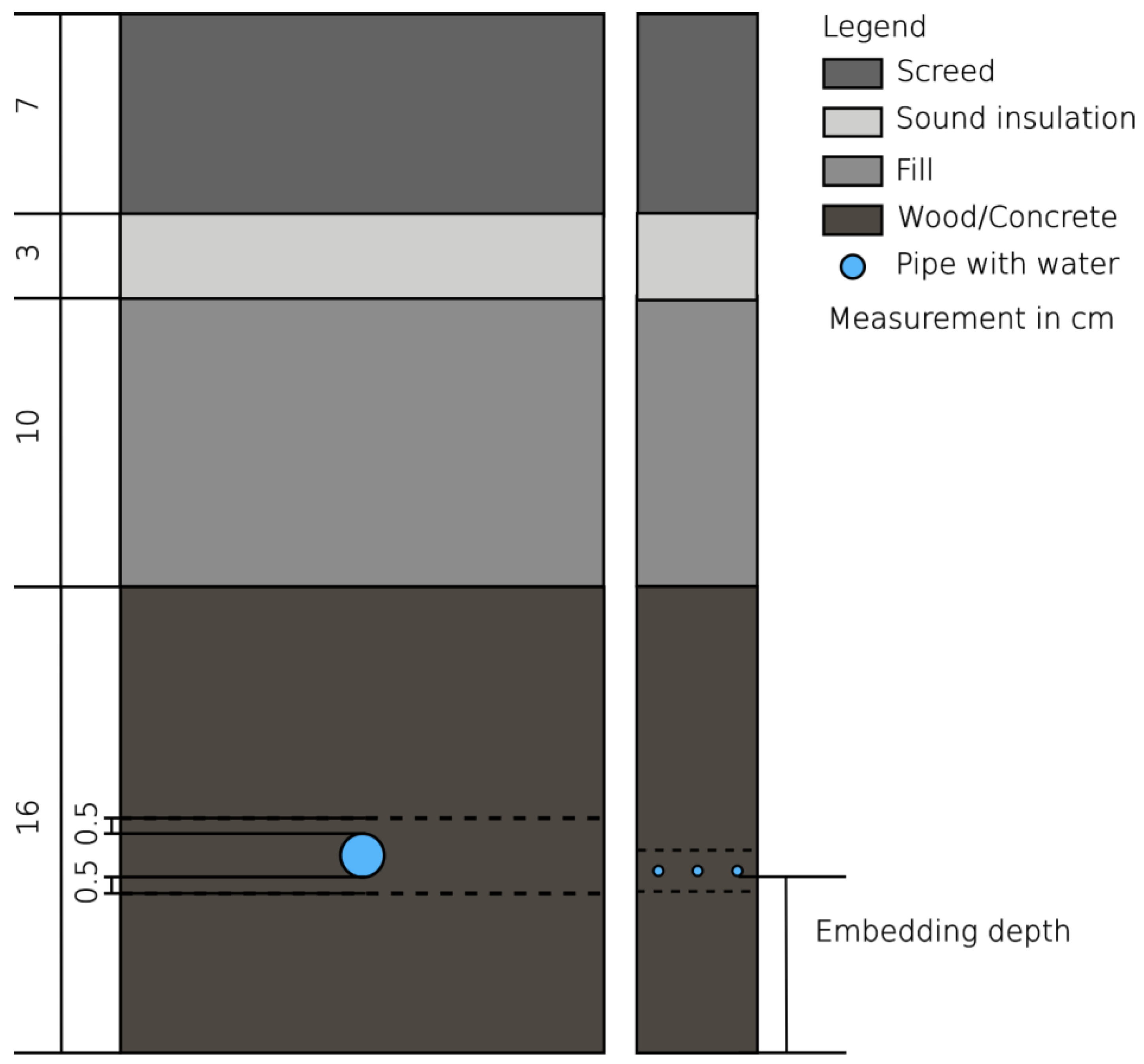
As this study focuses particularly on analyzing different types of wood, a solid timber ceiling construction was chosen as initial geometry. This consists of a 16 cm-thick wooden layer. Above this are layers of backfill (10 cm), insulation (3 cm) and screed (7 cm). The pipes are embedded in the wooden layer. This layer structure is also shown schematically in
Figure 1.
Several parameters were systematically varied as part of the simulation in order to analyze their influence on the thermal performance of the structure. All 120 cases were carried out as independent simulations without optimization algorithms. The applied methodology is generalizable, as the parametric framework in Delphin 6 allows the variation in arbitrary material properties, geometries, and boundary conditions. This makes the approach transferable to a wide range of construction types and operating scenarios. The parameters analyzed include and can be found in
Figure 2.
Pipe diameter and pipe spacing: These two parameters were considered together as they significantly affect heat distribution and release in the component.
Embedding depth: The vertical position of the pipes within the wood layer was varied to analyze the effect of different heat conduction paths on surface temperature and heat transfer efficiency.
Inlet temperature of the heating medium: Two different inlet temperatures were used to evaluate thermal behavior in various operating scenarios.
Use of different building materials: Concrete was used as the reference material. Additionally, four types of wood, a grass-based material, and four hybrid variants combining concrete or clay were analyzed to record differences in thermal performance dependent on the material used.
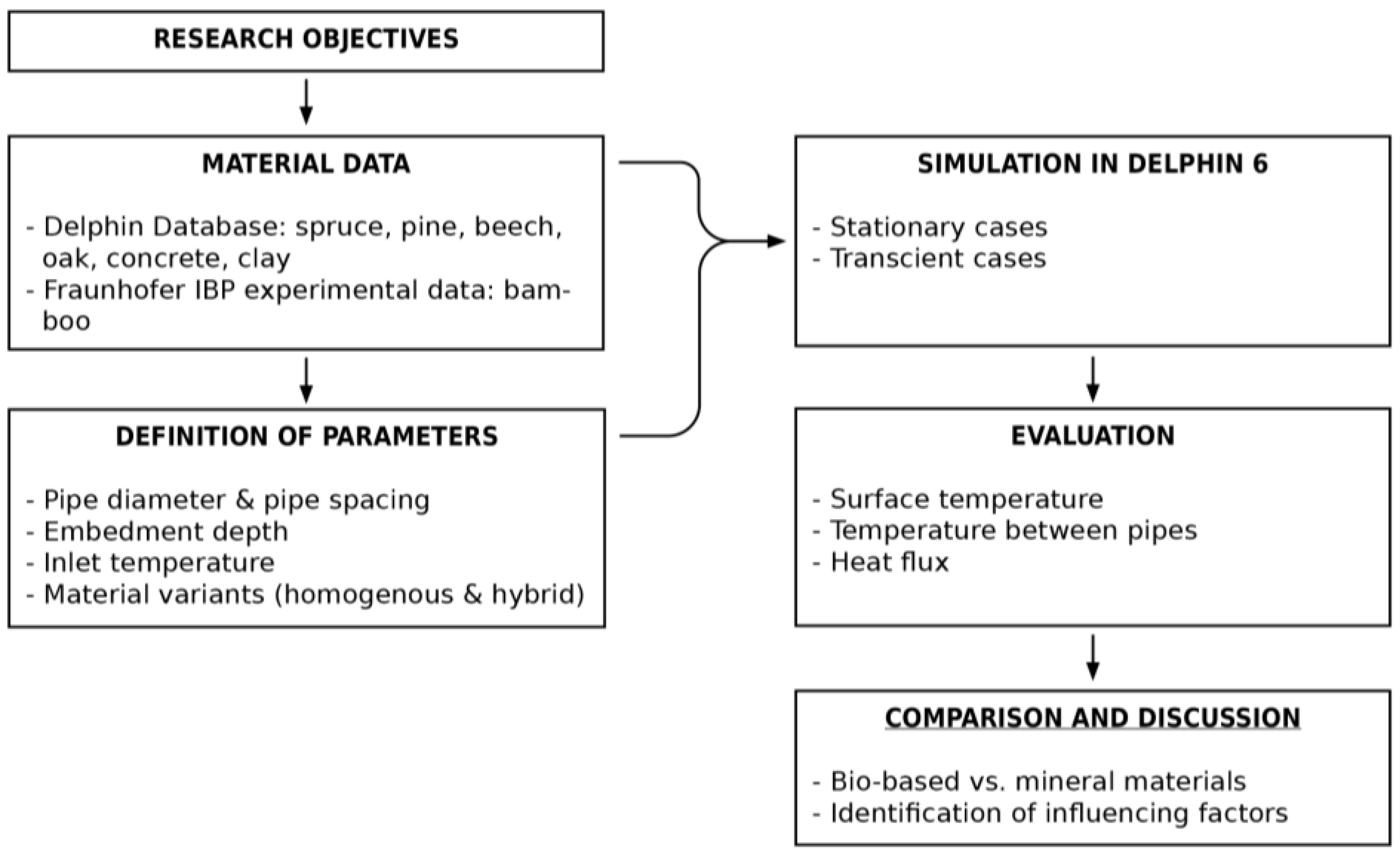
The simulation followed a structured workflow, as illustrated in
Figure 3. Starting from the research objective, the geometry of the slab layers was set up, and material properties were assigned. The parameters were systematically defined for each simulation case. Thermal simulations in Delphin 6 included both stationary analyses (temperature distributions) and transient analyses (heat storage capacity). Evaluation focused on surface temperatures, temperatures between the pipes and heat flux. Finally, the results were compared and discussed to highlight differences between bio-based and mineral materials and identify the most influential factors.
Notably, interdependencies exist among the studied parameters: pipe diameter and spacing jointly influence heat distribution; embedding depth interacts with the thermal conductivity of the material, affecting heat conduction pathways; and material selection modifies temperature distribution in combination with pipe parameters and inlet temperature of the water. By systematically combining these parameters and analyzing their interactions, a comprehensive understanding of the factors affecting the thermal performance of the investigated ceiling variants was achieved.
Figure 2.
Overview of all parameters which were varied.
Figure 2.
Overview of all parameters which were varied.
Figure 3.
Workflow of the parametric simulation.
Figure 3.
Workflow of the parametric simulation.
2.1. Pipe Diameter and Pipe Spacing
As part of the analysis of variation in pipe diameter and spacing, two different types of pipes were examined. One type was a conventional plastic pipe with an outer diameter of 16 mm and a wall thickness of 2 mm. This type of pipe is typically used in thermally activated component systems. The associated spacing of 15 cm corresponds to the standard dimension for this pipe size. Secondly, a capillary tube system was considered. For the simulation, an outer diameter of 4.3 mm and a wall thickness of 0.8 mm were assumed. In this case, the pipe spacing is 1 cm, which corresponds to the standard grid dimension for capillary systems. A major advantage of capillary tubes is their finer distribution, resulting in a more even heat transfer to the surrounding materials. Consequently, a more uniform surface temperature can be achieved, enabling lower inlet temperatures to be selected [
27]. This is achieved by the increased pipe surface area resulting from the narrower pipe spacing. The modeling aspect of the heat transfer of the pipe will be explained in later in the section on boundary conditions.
2.2. Embedding Depth
Three different depths were defined in order to analyze the embedding depth of the pipes: 6 cm, 3 cm and 1 cm. These were measured from the ceiling surface to the bottom edge of the pipe. These embedding depths were selected to model different concepts of thermal component activation. A depth of 1 cm represents activation close to the surface, which has the potential for a faster thermal reaction. The 6 cm embedding depth, on the other hand, is oriented towards classic systems with greater thermal inertia. The 3 cm variant is intended as an intermediate solution, offering a balance between reaction behavior and heat storage.
2.3. Inlet Temperature
As part of the investigation into the inlet temperature, the inlet temperature of the heating medium was varied. Two characteristic values were defined for this purpose: 26 °C and 35 °C. This variation was intended to analyze the influence of different temperature levels on the energy required to activate the component, as well as its suitability as a surface heating system. The lower temperature of 26 °C represents a scenario with minimal energy consumption, while the higher temperature of 35 °C represents operation under more conventional conditions, such as with underfloor heating. While this case focuses on a ceiling, the question arises as to whether a higher inlet temperature could be beneficial, particularly for wooden structures. This is because wood has a significantly lower thermal conductivity than concrete, which can affect the efficiency of heat transfer. By comparing the two temperature levels, it can be assessed whether increasing the inlet temperature in timber systems leads to a significant improvement in thermal performance.
2.4. Materials
In the simulation, concrete serves as the baseline, representing the reference case for comparing the different material variants, as this is the material currently most commonly used for TABS [
20]. The analysis focuses on two softwoods (spruce and pine), two hardwoods (beech and oak), and bamboo, which is a grass-based material. Spruce, pine, beech and oak were used from the material database of Delphin and analyzed by the laboratory of the IBK [
33]. For the bamboo the materials parameters were used from an experimental analysis by Fraunhofer IBP [
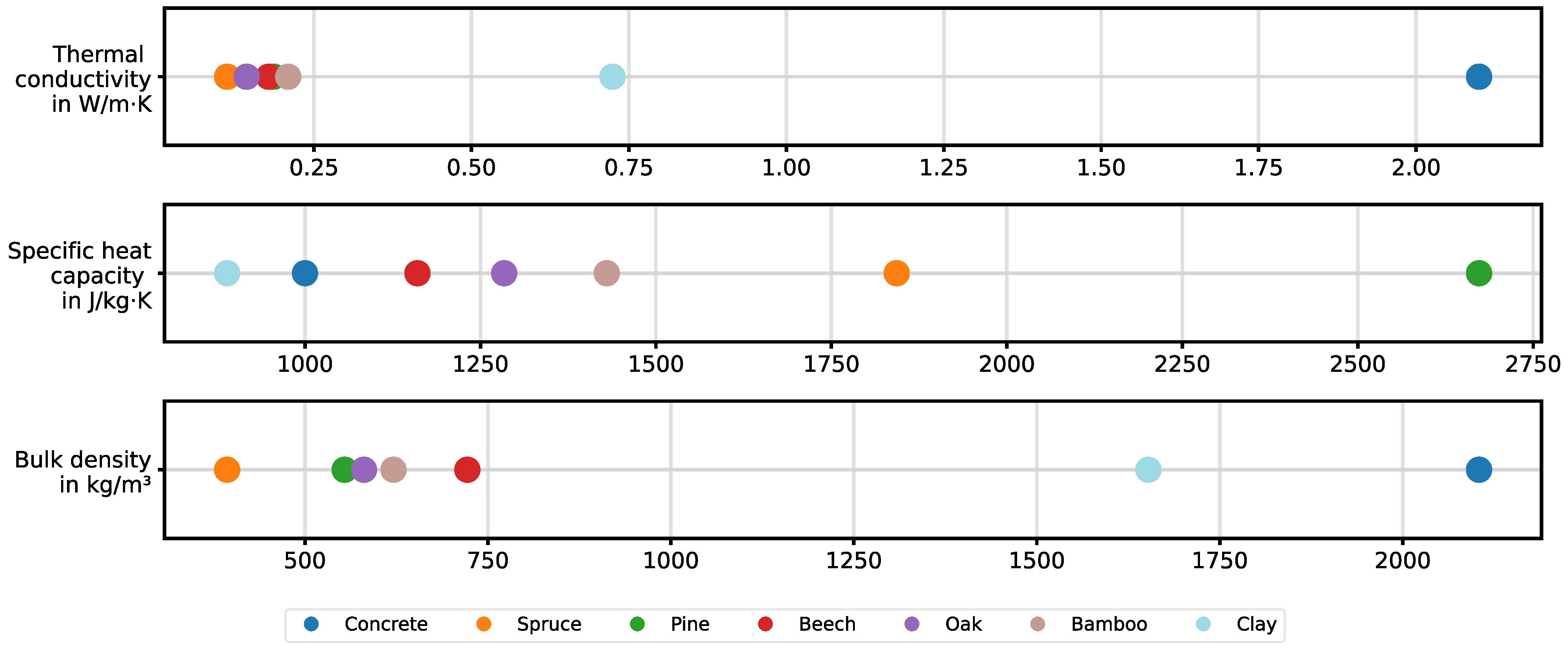
34]. These five materials were specifically selected because they differ significantly in terms of their thermal properties, such as thermal conductivity, and their bulk density. This is intended to cover a broad spectrum of possible heat transfer behaviors within wood and other natural materials. Additionally, four hybrid variants are analyzed, combining either concrete or clay with spruce or beech. In these hybrid structures, the pipe is embedded in the mineral layer (concrete or clay) with a 5 mm symmetrical overlap at the top and bottom. The basic idea behind these hybrid variants is to investigate whether a material with a higher thermal conductivity than wood can improve heat distribution in the building component. The aim is to thermally activate a larger surface area, and therefore a larger mass, of the component. So far, the integration of such a layer has only been conceived theoretically. Further studies would be required to examine the practical implementation and physical and structural feasibility. An overview of the thermal properties is provided in
Figure 4. Additionally,
Figure 1 shows the homogeneous and hybrid variants schematically.
2.5. Boundary Conditions
The boundary conditions at the top and bottom edges of the component in question are defined as a constant temperature of 20 °C. This serves as an assumed room temperature, representing an idealized thermal effect on the surface. The lateral edges are adiabatic, meaning there is no heat transfer via these sides. The pipes are arranged symmetrically around the component geometry, meaning the adiabatic edges act as axes of symmetry. This reduces the calculation area required for modeling.
In the simulation, the pipes are modeled as square cross-sections. The edge length of these squares corresponds to the outer diameter of the real pipes. The convective heat transfer boundary condition integrated in Delphin is used to model pipes with flowing fluid. Therefore, the adaptive model with inlet temperature is used in Delphin. A detailed description of how the heat transfer coefficient is calculated can be found in the publication by Weiß et al. [
35].
Both models analyzed use a PE pipe with a thermal conductivity of 0.4 W/(m·K). The flow velocity of the water is 0.5 m/s. The corresponding mass flow was then determined based on the respective pipe cross-section.
2.6. Evaluation Parameters
The following measured variables are analyzed in the steady state:
the temperature at the surface directly beneath the pipe
the temperature at the center of the surface between two pipes
the temperature at the center of the component between two pipes.
This analysis aims to investigate how the embedding depth of the pipework influences the resulting surface temperature. Additionally, the impact of pipe spacing on heat distribution uniformity is evaluated. Based on these findings, conclusions can be drawn about the extent to which the thermal mass of the component is activated.
In addition to the stationary observation, a dynamic load case was simulated to analyze the thermal storage behavior of the components. Once the system had reached steady state, it was kept in equilibrium for a defined period to ensure a stable starting point. The mass flow of the heating medium was then reduced to zero to prevent any further heat being introduced by forced convection. Subsequent cooling then took place exclusively through heat conduction within the component.
The heat conduction flux on the component surface can be used to track temperature development over time and estimate the system’s cooling down time.
3. Results
The results show that the analyzed parameters significantly influence the performance of the thermal system. The effects are illustrated by analyzing the individual parameters separately below.
Ten material variants were analyzed as part of the investigation, including homogeneous building materials such as concrete, spruce, pine, oak, beech and bamboo, as well as hybrid combinations with clay and concrete. It was found that most of the materials, particularly pine, oak, beech and the hybrid combinations, had very similar values with regard to the relevant thermal parameters (e.g., surface temperature and temperature distribution). The differences were typically in the range of 0.45 K to 2.1 K for the bio-based materials, resulting in only minor deviations from the reference or extreme values.
For clarity and to maximize the informative value, the presented results focus on characteristic cases, i.e., the material with the best and worst performance, the most efficient bio-based material and the most efficient hybrid material, as well as a comparison with conventional concrete.
3.1. Influence of the Material Used
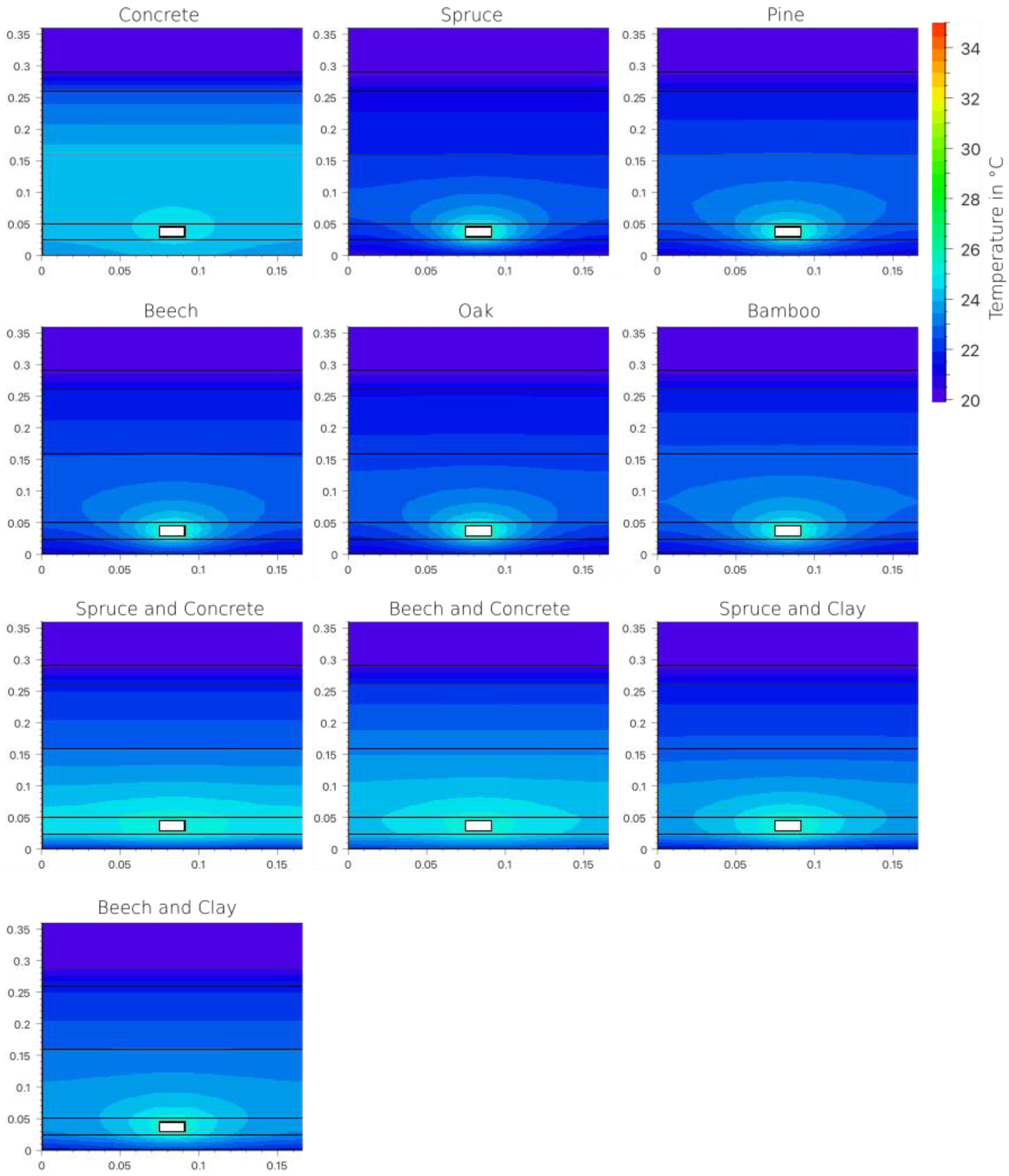
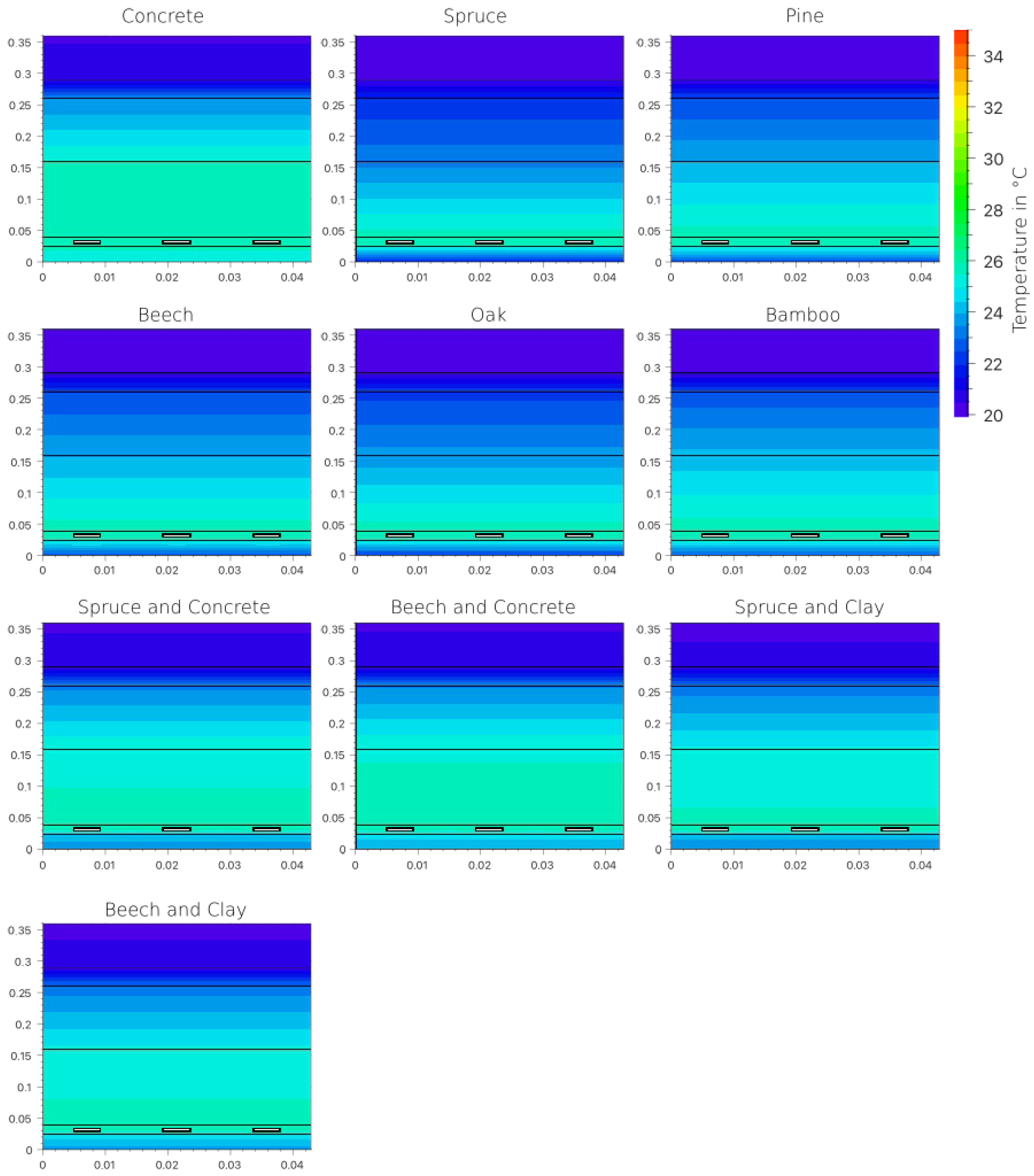
The material analysis is based on a model with an embedment depth of 6 cm, an outer pipe diameter of 16 mm and a water temperature of 35 °C.
Figure 5 also shows the parameters used. The surface temperature directly below the pipe is used as the reference value.
The highest temperature was measured in the concrete base material at 29.31 °C. Spruce had the lowest temperature, at 21.99 °C. Among the homogeneous, bio-based materials, bamboo showed the highest temperature of 23.22 °C. Among the hybrid variants, the combination of beech and concrete achieved 23.79 °C, closely followed by beech and loam at 23.51 °C. Depending on the material, the temperature difference interval was between 5.52 K and 7.32 K. The corresponding temperature distributions are shown in
Figure 6. This clearly demonstrates the impact of the materials’ varying thermal conductivities.
The corresponding thermal conductivities were summarized in
Figure 4. Concrete had the highest thermal conductivity (2.1 W/(m·K)), while spruce had the lowest (0.112 W/(m·K)). Bamboo tops the list of bio-based materials with a value of 0.209 W/(m·K).
3.2. Influence of Pipe Size and Spacing
Models with an embedment depth of 3 cm and a water temperature of 26 °C were analyzed to evaluate the pipe size and spacing.
Figure 7 also shows the parameters used. Evaluations were carried out at two positions: in the center between pipes at the same height, and at the surface below.
At the center between the pipes, the temperature spread was 1.84 K at a distance of 15 cm (pipe diameter: 16 mm). With a minimum pipe spacing of 1 cm (capillary tubes), this decreased to 0.19 K.
Temperatures in the center between the pipes varied depending on the material. In the 16 mm pipe system, the spruce model showed the lowest value of 22.36 °C and the spruce-concrete hybrid model showed the highest value of 24.73 °C. Concrete itself reached 24.2 °C and bamboo 22.74 °C. The temperatures can be seen in
Figure 8. Further,
Figure 9 shows the temperature distribution in the components for all the different materials used with a pipe diameter of 16 mm.
The temperature for the capillary tubes in concrete was 25.74 °C. Spruce and bamboo were almost on a par, with values of 25.79 °C and 25.78 °C, respectively—the highest values measured in this scenario. The hybrid spruce–concrete model achieved a value of 25.60 °C, the lowest measured. The corresponding distributions are shown in
Figure 8 and
Figure 10.
The influence of pipe spacing can also be seen on the surface between two pipes. Spruce exhibited the lowest temperatures, reaching 20.67 °C with a 16 mm thickness and 21.85 °C with a capillary tube. Bamboo was the most effective bio-based material, reaching 21.18 °C (16 mm) and 22.69 °C (capillary tube). Concrete reached 23.72 °C (16 mm) and 25.13 °C (capillary tube). The best hybrid solution (beech-concrete) reached 22.12 °C and 24.22 °C, respectively. The corresponding temperature distributions are shown in
Figure 11. Overall, it is evident that increasing the pipe surface area affects the temperature distribution within and on the surface of the component.
3.3. Influence of Embedding Depth
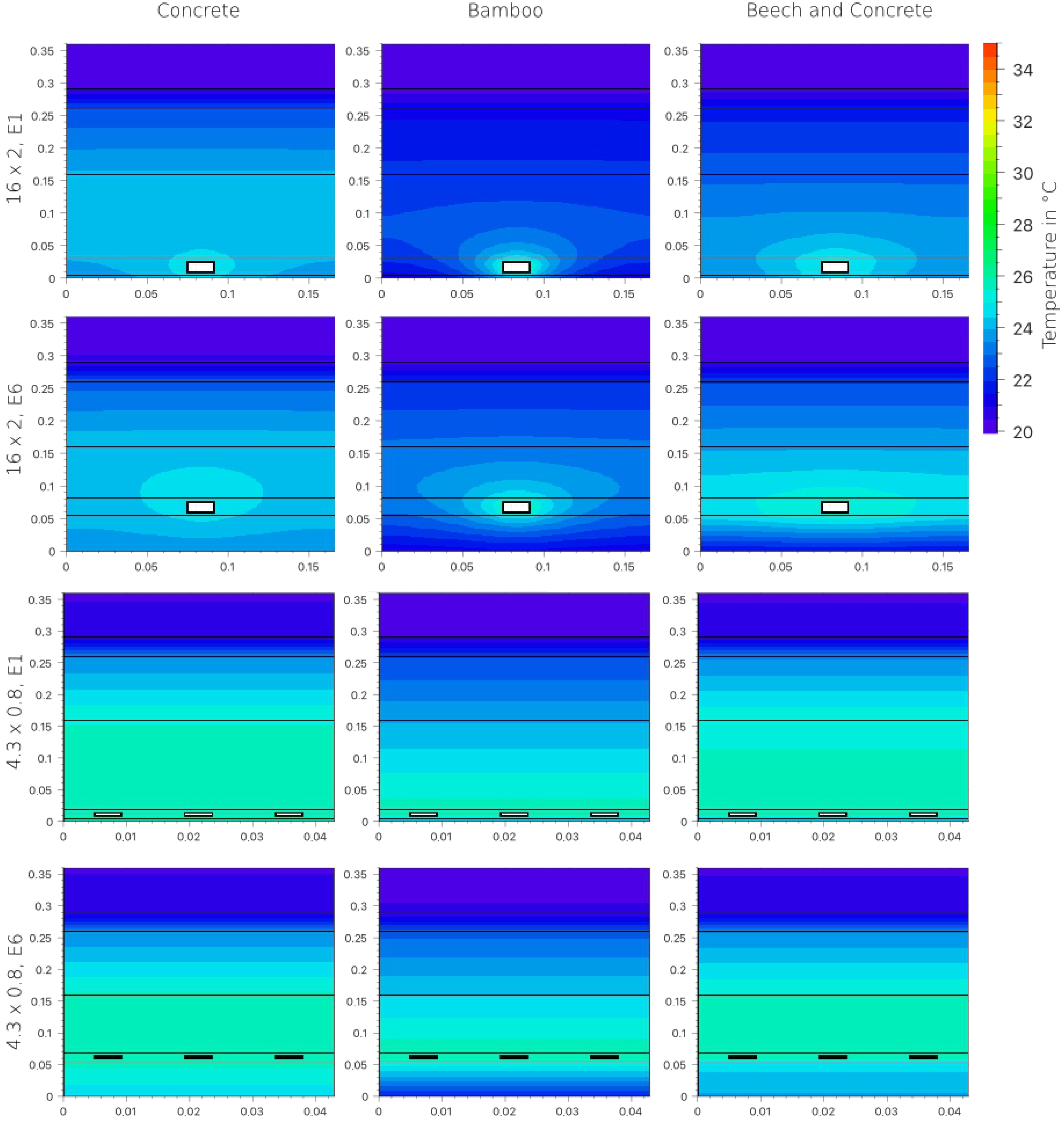
The influence of the embedding depth was analyzed by comparing 6 cm and 1 cm depths at a water temperature of 26 °C. The 16 mm pipe system and the capillary tube system were both analyzed.
Figure 12 also shows the parameters used.
In the 16 mm model, the concrete had the highest surface temperatures under the pipe: 23.67 °C (6 cm) and 24.6 °C (1 cm). Spruce exhibited the lowest values, at 20.79 °C and 23.12 °C, respectively. Bamboo was at 21.28 °C (6 cm) and 23.73 °C (1 cm). The hybrid beech-concrete model exhibited a notable temperature increase, ranging from 21.5 °C (6 cm) to 24.08 °C (1 cm).
Figure 13 shows the temperature distributions.
The effect was even clearer with capillary tubes. The spruce variant’s temperature rose from 21.11 °C (6 cm) to 23.33 °C (1 cm) and the bamboo variants from 21.78 °C to 24.11 °C. Concrete showed smaller differences here: 24.67 °C (6 cm) and 25.49 °C (1 cm). The hybrid model also showed a moderate increase. The results are shown in
Figure 14 and
Figure 15. Therefore, the influence of the thermal conductivity can be emphasized once again. It represents greater resistance at lower values with a higher embedding depth.
3.4. Influence of the Water Temperature
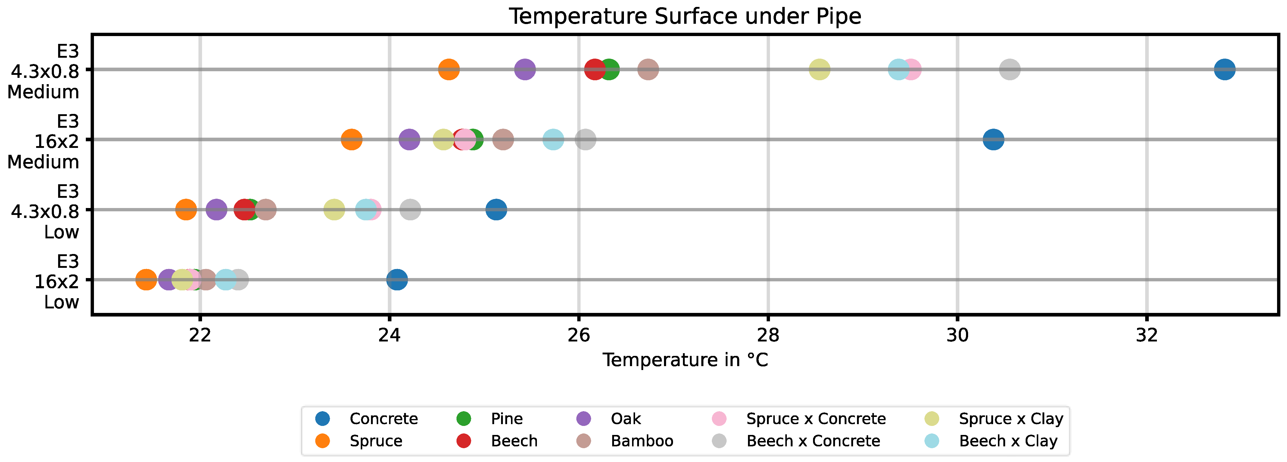
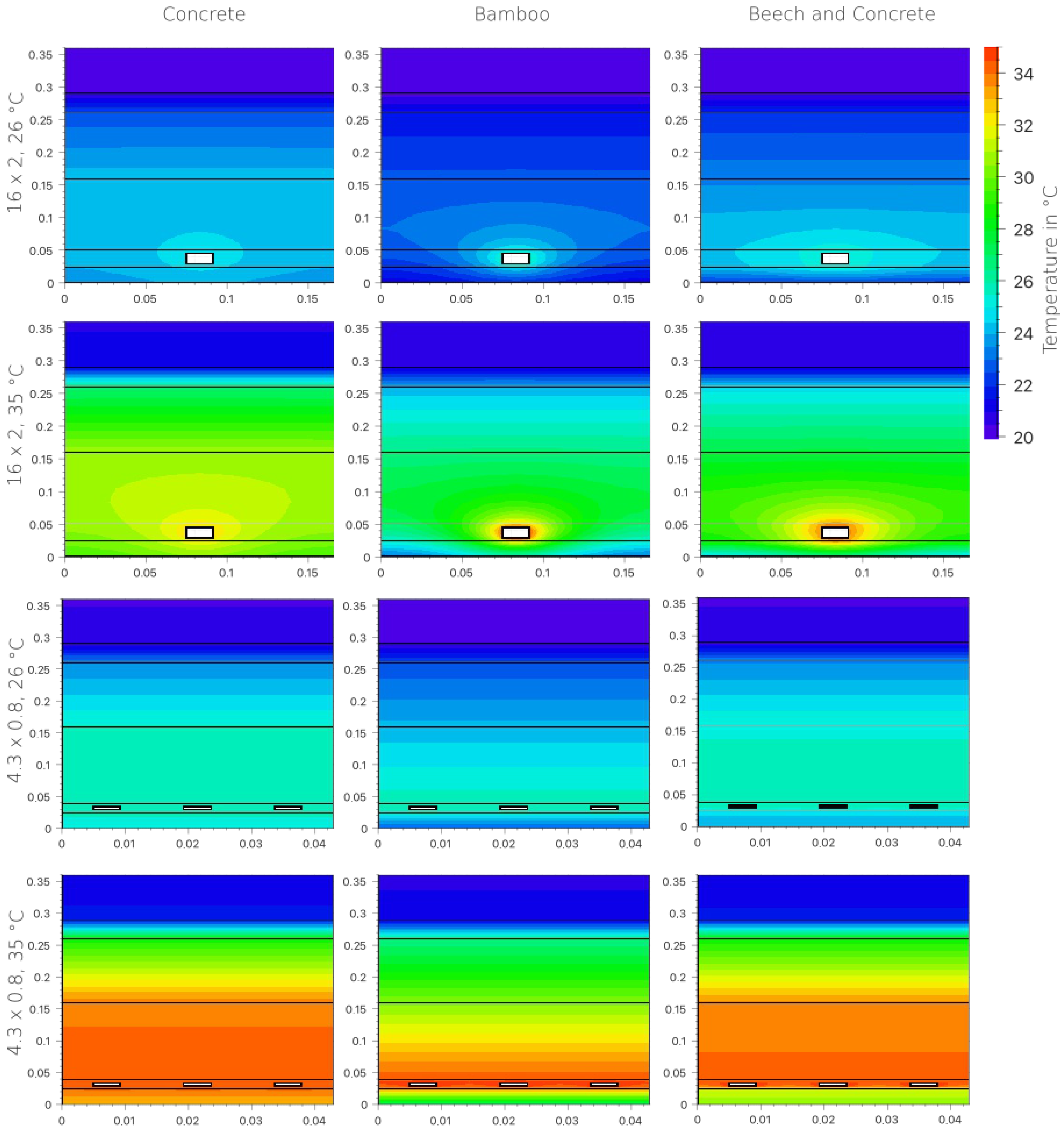
The inlet temperature considerably influences the temperature level and spreads. A model with an embedment depth of 3 cm and 16 mm pipes was analyzed at inlet temperatures of 26 °C and 35 °C.
Figure 16 also shows the parameters used.
The difference between the highest and lowest surface temperatures under the pipe was 2.65 K at 26 °C and increased to 6.78 K at 35 °C. The minimum surface temperature was observed for spruce at 21.43 °C (26 °C inlet temperature) and 23.6 °C (35 °C inlet temperature). The highest values were achieved with concrete: 24.08 °C and 30.38 °C, respectively.
Figure 17 and
Figure 18 show the complete temperature distributions. The higher heat transfer caused by the higher water temperature is evident here. This behavior is further reinforced by a lager heat transfer area of the pipes at the models with the capillary tubes.
3.5. Influence of the Heat Storage Capacity
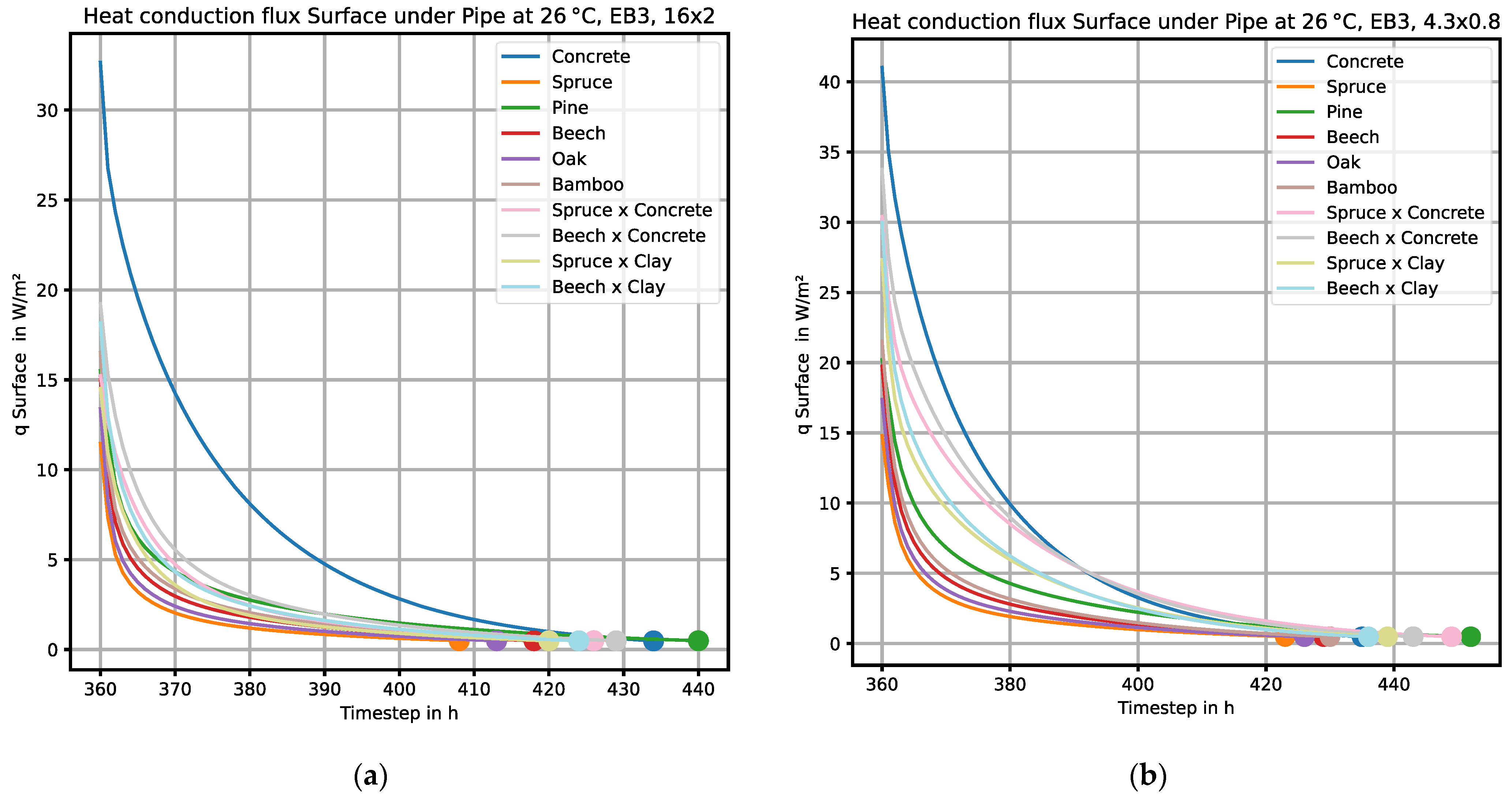
The heat storage capacity was determined by measuring the cooling time after the system reached a steady state with a zero-mass flow. The limit value was set at 0.5 W/m
2.
Figure 19 shows the heat flow curve at a boundary condition of an inlet temperature 26 °C and an embedded depth of 3 cm. The start time here is 360 h, as the simulation should take sufficient time to stabilize at a steady state.
The curves show that, after concrete, pine has the highest storage potential. Bio-based materials absorbed significantly less heat than concrete. Hybrid materials also exhibited a low storage effect.
Capillary tubes considerably extended the cooling down time. In the concrete model with an embedment depth of 3 cm, the cooling time was around 71 h with 16 mm pipes and around 75 h with capillary tubes. Similar effects were seen with other materials. Pine performed best consistently among the bio-based materials. With pine the cooling down time extends on additional 12 h by using capillary tubes instead of using the regular pipes. By comparing concrete and pine, the influence of the specific heat capacity in combination with the bulk density is highlighted.
Figure 4 also underlines the influence of the specific heat capacities, particularly in the hybrid models.
4. Discussion
The numerical simulations of this study show that all analyzed parameters—material, pipe spacing, water temperature, embedment depth, and heat storage capacity—significantly influence the system’s thermal performance. The results are analyzed in the context of thermal component activation below.
4.1. Influence of the Material
Concrete has the most favorable thermal properties due to its high thermal conductivity (λ = 2.1 W/(m·K)) and heat capacity. The significantly lower surface temperatures of spruce and other bio-based materials illustrate the limiting effect of their low thermal conductivity (e.g., spruce: λ = 0.112 W/(m·K)). Among bio-based materials, bamboo shows comparatively favorable behavior with a thermal conductivity of 0.209 W/(m·K). This highlights the potential for optimization through the targeted selection of bio-based materials.
Hybrid materials, such as beech-concrete or beech-clay, have better temperature distribution than solid bio-based materials. This is due to the thermal bridging effect of the mineral component. The higher temperatures in the area between pipes with a diameter of 16 mm can be explained by the insulating effect of the wood matrix, which has a low thermal conductivity.
Overall, the results demonstrate that suitable combinations of materials can be used to achieve efficient heat conduction in the vicinity of the pipes, as well as improved distribution and storage throughout the entire component. Hybrid materials therefore offer a functional optimization strategy that combines the advantages of the low CO2 footprint of bio-based materials with the high thermal storage capacity of mineral components.
4.2. Influence of Pipe Size and Spacing
A closer spacing in combination with a smaller size of the pipes leads to a more homogeneous temperature distribution and greater activation of the component. For instance, the temperature variation decreases from 1.84 K at a spacing of 15 cm to just 0.19 K at a spacing of 1 cm (capillary tubes) at an embedment depth of 6 cm. For materials with low thermal conductivity in particular, a narrow pipe spacing is crucial to achieving surface temperatures similar to those of concrete. This phenomenon can be attributed to the increased surface area of the pipe, which in turn leads to an elevated heat transfer area.
The results of the simulations suggest that the relative temperature benefit of closer pipe spacing is less pronounced in bio-based materials than in hybrid systems. This can be explained with the different thermal conductivities of the different materials of the hybrid structures. However, the findings indicate that bio-based materials can be utilized effectively in conjunction with capillary tube systems, thereby ensuring uniform activation despite their reduced thermal conductivity.
4.3. Influence of Embedment Depth
The embedment depth primarily affects the surface temperature, whereas the temperature around the pipe varies less. A shallower embedment depth (e.g., 1 cm instead of 6 cm) achieves higher surface temperatures due to the shorter heat path. This effect is more pronounced with bio-based materials, as their thermal conductivity is lower. This result is in agreement with Bishara et al. [
30]. Therefore, reducing the embedment depth can help increase efficiency, particularly when using bio-based materials.
4.4. Influence of Water Temperature
An increase in the inlet temperature increases both maximum surface temperature and temperature spread. This has two main consequences:
Increased heat output due to more intensive thermal activation.
Lower thermal homogeneity, which can lead to a loss of comfort, for example, in floor applications.
Simulations show that bio-based materials do not significantly improve in performance, even at higher water temperatures. This confirms that their thermal limitations cannot be overcome by increasing the inlet temperature alone. This was also shown by Heidenthaler et al. [
31].
The results suggest that uniform activation of the component is possible even with a moderate water temperature of 26 °C in combination with close pipe spacing.
4.5. Influence of the Heat Storage Capacity
Analyzing the cooling out phases reveals that materials with a high specific heat capacity, such as concrete and pine, release heat over longer periods. Similar results can be seen in Heidenthaler et al. [
31]. Using capillary tubes also extends the cooling out time, indicating more even heat distribution and more effective component activation. The storage potential of some bio-based materials, especially pine, is notable. This makes them promising candidates for intermittent heating operations, as well as applications involving load shifting or time-delayed energy supply, such as when using heat pumps. In this context, the parameters of the specific heat capacity and the bulk density play a decisive role in determining the suitability of a material for load-shifting applications, as it directly influences the amount of energy stored.
4.6. Universality of Results
Although the study is based on 120 independent parametric simulations, the findings can be considered transferable beyond the investigated cases. The methodology builds in fundamental principles of heat conduction and thermal storage, which are universally valid and not restricted to a specific software implementation. Moreover, the parametric framework with Delphin 6 enables systematic variation in material properties, geometries, and boundary conditions, which makes the approach adaptable to a wide range of construction types and operating scenarios. The influence patterns observed in this work—such as the role of the pipe spacing in achieving thermal homogeneity or the effect of embedment depth on the surface temperature—are consistent with physical reasoning and align with trends reported in previous studies. Taken together, these aspects demonstrate that the results are not limited to an isolated case study but provide insights of broader applicability.
5. Conclusions
The present study shows that bio-based building materials have promising potential for use in thermally activated building components for load shifting. While previous research, as referenced in the literature reviews [
7,
8], focused primarily on mineral-based TABS, this study provides the first systematic numerical evaluation of bio-based material under a wide range of operational and design parameters, including pipe diameter, spacing, embedment depth and inlet temperature. Although bio-based materials have a lower thermal conductivity than mineral materials such as concrete, comparable thermal performance can be achieved through suitable design measures, such as reducing the embedment depth and spacing the pipes more closely, for example, by using capillary tube systems. Among the bio-based materials, bamboo and pine stand out favorably. Hybrid material combinations with clay or concrete offer additional optimization potential by improving heat distribution and reducing the ecological footprint simultaneously. However, these are theoretical constructions that have not yet been realized in practice. In conclusion, the findings of this study demonstrate that through design optimization (e.g., closer pipe spacing, reduced embedment depth), bio-based materials can achieve comparable activation performance to concrete in TABS, thus expanding the potential material palette for sustainable building design.
A key limitation of this study is that it represents a purely numerical first step without experimental validation. While the parametric simulation provides systematic insights into the thermal behavior of bio-based and hybrid slabs, experimental investigations will be essential to validate and calibrate the findings under real boundary conditions. Such validation is foreseen as the logical next step of this research. Limitations of the study include further the focus on heating applications only, since cooling with bio-based materials involves a considerable risk of condensation. Due to the moisture-absorbing properties of wood and similar materials, condensation can lead to moisture buildup inside the components, which may cause damage such as mold growth or material degradation over time. Because of these risks, cooling scenarios were excluded from this study to maintain focus on thermal performance during heating. In addition, the simulation assumed dry material properties, and moisture content was not included, which may influence thermal performance in real-world conditions. Future research needs to address moisture control and condensation prevention to enable safe use of bio-based materials in cooling applications. A further limitation concerns the practical feasibility of the proposed (hybrid) building component. While the simulations show building physical potential, realization in practice would require interdisciplinary evaluation regarding load-bearing capacity and long-term behavior.
Simulations also demonstrate that the heat storage capacity of certain bio-based materials could be utilized for load shifting and intermittent operation, e.g., in conjunction with heat pumps or solar energy sources. Therefore, bio-based materials could play a significant role in decarbonizing the construction industry. Future research should focus on the practical implementation of such hybrid systems, as well as on their long-term behavior and building physics boundary conditions. Including also a carbon impact assessment would further enhance the sustainability evaluation of bio-based materials. This type of assessment could include embodied CO2 or GWP. Moreover, future research should prioritize experimental validation of hybrid systems, assessment of construction feasibility including prefabrication potential, and evaluation of load-bearing capacity and long-term performance under realistic environmental conditions. Additionally, the influence of moisture and condensation must be thoroughly investigated, as these factors critically affect durability and safe application, especially given the moisture-absorbing nature of bio-based materials. Addressing these challenges is essential to enable practical implementation and ensure reliable performance in real-world building environments. Future work should also explore AI-based surrogate modeling approaches such as physics-informed neuronal networks to accelerate parametric studies of bio-based TABS for load shifting.

