Abstract
As a carbon-free fuel, ammonia faces challenges in engine applications due to its low flame propagation speed and high ignition energy. The pre-chamber turbulent jet-post spark ignition strategy (TJ-PSI) has been proven effective in accelerating the combustion of stoichiometric ammonia/air mixtures. This study investigates the effects of orifice configuration on the combustion characteristics of stoichiometric ammonia/air premixed mixtures under TJ-PSI mode. Experiments are performed in a constant-volume combustion vessel filled with stoichiometric ammonia/air mixtures, and the spark plug used to trigger the ignition of the mixture in the main chamber is located downstream of the pre-chamber turbulent jet flow. With pre-chamber volume maintained constant, pre-chambers with different orifice numbers (Φ1.4 mm × 1, Φ1.4 mm × 4, Φ1.4 mm × 6) and orifice diameters (Φ4.0 mm × 1) are tested, along with varying time intervals (TI) between the main chamber and pre-chamber spark timings. Experimental results show that the pre-chamber with single large orifice (Φ4.0 mm × 1) produces jet flames but offers limited combustion enhancement. In contrast, a single small orifice (Φ1.4 mm) generates flameless turbulent jets, which reduce combustion duration by 53% compared to the large-orifice case. This improvement is attributed to the pre-chamber jet enhancing turbulence in the main chamber, whereas larger orifices yield lower turbulence intensity. Although multi-orifice configurations provide less pronounced enhancement compared to the single-orifice case, they effectively prevent flame kernel extinction at short TIs (e.g., 10 ms). Consequently, the total combustion duration from pre-chamber spark to the end of main chamber combustion can be significantly shortened.
1. Introduction
Ammonia is a carbon-free and renewable hydrogen carrier that offers advantages in storage and transport compared to compressed or liquefied hydrogen (which requires high compression pressure to achieve favorable energy density) [1,2]. Thus, ammonia holds potential as an alternative fuel to today’s hydrocarbon fuels for reducing CO2 emissions in engines [3]. However, significant technical challenges remain due to the combustion characteristics of ammonia. The laminar flame propagation velocity of ammonia is significantly lower than that of gasoline or diesel fuel [4]. Furthermore, the minimum ignition energy of ammonia is around 8 mJ, significantly higher than that of gasoline (around 0.14 mJ), making it harder to ignite and sustain stable combustion without advanced ignition systems [5]. This leads to a longer combustion duration and lower combustion heat release rate in ammonia engines [6,7] posing a major challenge to its practical application in engines [8,9].
Recent studies have proposed several advanced ignition and combustion enhancement strategies to address these challenges. For instance, plasma-induced ignition [10] has been shown to effectively promote ammonia combustion by generating highly reactive radicals through plasma discharge, which significantly reduces ignition energy and enhances flame propagation stability. Similarly, multiple-spark ignition strategies [11] have been explored to optimize the combustion process. By creating multiple ignition sites, this approach improves the initiation of flame kernels and reduces cycle-to-cycle variations, especially under lean or low-reactivity conditions. Although these methods exhibit notable benefits in terms of ignition energy utilization and combustion efficiency, their practical application is often hindered by issues such as high system complexity and increased energy consumption.
In this context, pre-chamber-based turbulent jet ignition emerges as a promising alternative approach. This method can achieve comparable ignition enhancement, while maintaining a simpler configuration and lower energy demand relative to plasma or multiple-spark systems.
Turbulent jet ignition (TJI) strategy has been used to enhance ammonia engine combustion, which is due to its advantages of multi-point ignition and high ignition energy compared to most conventional ignition methods [12,13]. It has been applied to enhance combustion performance in ammonia engines by dividing the combustion process between a pre-chamber and a main chamber connected by small orifices. The spark-ignited mixture in the pre-chamber generates a turbulent jet rich in reactive radicals and combustion products, creating multiple ignition points in the main chamber and accelerating the propagation of flame [14,15]. Biswas et al. [16] experimentally demonstrated two distinct TJI ignition modes, “flame ignition” and “jet ignition”. As the orifice diameter and pre-chamber pressure increase, the ignition mode transitions from jet ignition to flame ignition.
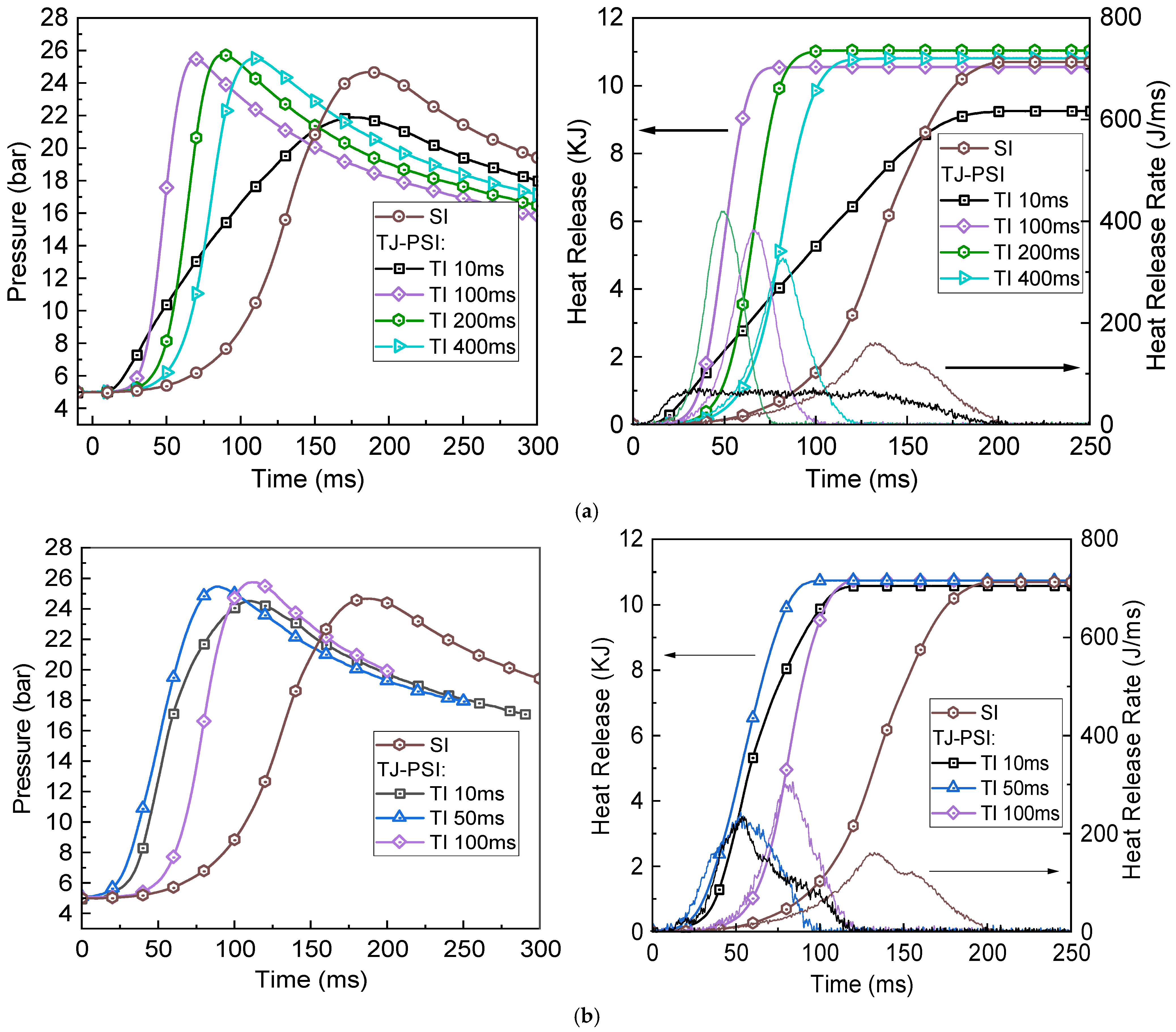
In previous studies, a new combustion approach, which integrates turbulent jet with post-spark ignition (TJ-PSI), was introduced to enhance the combustion of ammonia fuels [17]. For TJ-PSI strategy, a spark plug is positioned in the pre-chamber, while the other is located in the main chamber downstream of the jet. The ignition of the premixed stoichiometric ammonia/air mixture is achieved by the two spark plugs’ ignition process. After the first ignition process of the spark plug in the pre-chamber, a turbulent jet of mixture is ejected into the main chamber, where the spark plug in the main chamber conducted the post-ignition process to ignite the mixture after a specific ignition time interval. Comparative analysis of combustion characteristics between spark ignition (SI) [18] and TJ-PSI modes reveals that TJ-PSI better utilizes the turbulent kinetic energy of the mixture jet. This significantly enhances ammonia combustion, shortens combustion duration, and improves combustion intensity, provided that ignition time intervals are appropriately set. However, insufficient time intervals can result in flame kernel quenching, as the high-velocity turbulent jet disrupts the post-ignition process. To prevent this, time intervals exceeding 100 ms are required, which are far longer than the typical 10–20 ms combustion duration of conventional engines, posing a challenge for practical engine applications.
The turbulence intensity of pre-chamber jet directly affects the combustion characteristics of TJ-PSI strategy, while the pre-chamber geometry determines the jet properties [19]. Previous studies have extensively explored the impact of pre-chamber structures on combustion characteristics, with findings emphasizing the significant role of structural parameters in influencing jet turbulence intensity [20]. For instance, Cui et al. [21] demonstrated that the volume and orifice diameter of the pre-chamber significantly affect the combustion dynamics of ammonia/air premixed fuel ignited with jet flame ignition and found that the size of the orifice diameter determines whether the jet emitted from the pre-chamber manifests as a jet flame or as flameless jet carrying high-temperature gas products. Tang et al. [22] proposed that optimizing the throat diameter of narrow-throat pre-chambers enhances pressure buildup, accelerates jet penetration, and reduces combustion duration. Similarly, Huang et al. [23] found that the arrangement of orifices in passive pre-chambers substantially influences fuel combustion performance. Further investigations by Wang et al. [24] revealed that the total cross-sectional area of pre-chamber nozzles has the most pronounced effect on combustion performance and lean combustion limits. Their study also examined the effects of transition angles, throat diameters, and orifice number on turbulent jet ignition. Yang et al. [25] explored the influence of internal volume ratio, nozzle angles, orifice diameters, and orifice number on lean combustion in active pre-chamber jet ignition engines. Xie et al. [26] observed that with the increase of surface-to-volume ratio and cross-section ratio (i.e., the diameter of the jet orifices), the penetration distance and distribution area of the jet flame both show a trend of increasing first and then decreasing. Thus, the orifice diameter of the pre-chamber significantly influences jet properties and hence influences the combustion performance of premixed mixture in the main chamber. Despite these advances, no study has specifically investigated the combined impact of the number and diameter of orifices in pre-chambers on combustion characteristics of premixed ammonia/air mixtures under TJ-PSI mode.
Therefore, this study examines how the pre-chamber geometry, including the orifice number and diameter, influences the characteristics of ammonia combustion using the TJ-PSI approach. The study further explores the potential of these structural optimizations to prevent flame kernel extinction, a critical challenge in ammonia combustion.
2. Experimental Setup
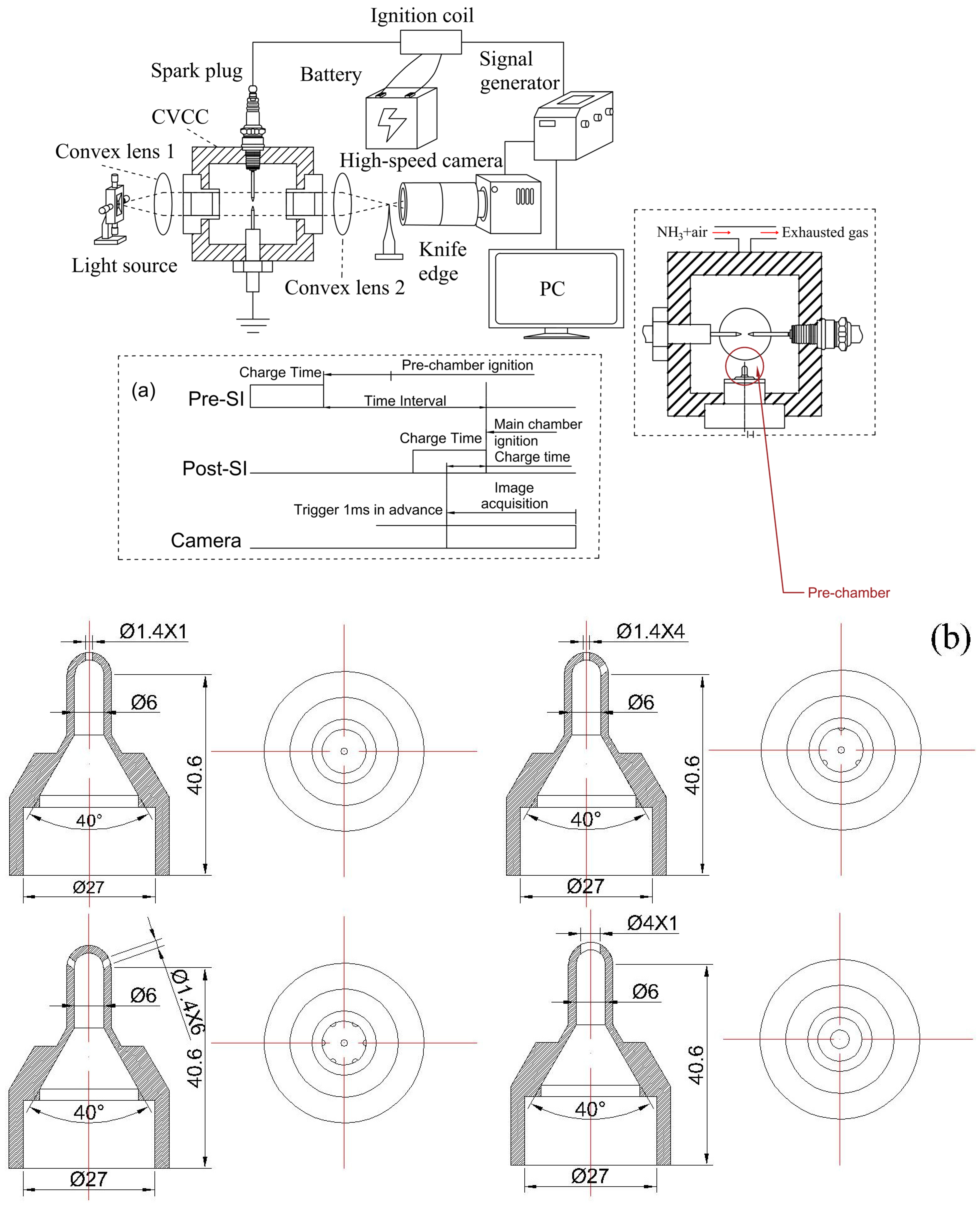
Figure 1 illustrates the schematic diagram outlining the experimental setup. Except for the pre-chamber structure differences, the rest of the setup remains consistent with those used in the previous work [17]. According to previous studies, the pre-chamber geometry has large effects on the combustion characteristics of TJI strategy [27,28]. The experiment focuses on how different pre-chamber orifice configurations influence the key combustion characteristics of a premixed ammonia/air mixture, using TJ-PSI strategy in a cylindrical constant volume vessel (CVV). The main chamber of CVV has a volume of 1.47 L. The experimental temperature is maintained at 393 ± 5 K. A pre-chamber with a volume of 9.9 mL (Figure 1b) is positioned at the CVV’s bottom center and equipped with a Bosch FR7SE spark plug (Bosch, Gerlingen, Baden-Württemberg, Germany) to generate turbulent jets. Two identical Bosch FR7SE spark plugs (Bosch, Gerlingen, Baden-Württemberg, Germany) are used in the experiment. The one located in the main chamber, is modified into a pin-to-pin configuration, with the electrode gap to the ground electrode set to approximately 2 mm. The initiation energy is about 20 mJ. The initial equivalence ratio of the mixture in both chambers is set to φ = 1.0 and the initial pressure is 5 bar. Post-ignition in the main chamber is achieved using a modified Bosch FR7SE spark plug (Bosch, Gerlingen, Baden-Württemberg, Germany) with an electrode gap of approximately 2 mm, positioned about 20 mm above the nozzle of the pre-chamber. The pre-chamber configurations tested in this study include single-orifice pre-chambers with orifice diameters of 1.4 mm and 4 mm, as well as four-orifice and six-orifice pre-chambers with an orifice diameter of 1.4 mm. These configurations are examined to evaluate the impacts of orifice diameter and number on the main combustion characteristics of stoichiometric ammonia/air mixtures under TJ-PSI mode.

Figure 1.
Experimental setup. (a) Temporal configuration of trigger signals; (b) Structure diagram of the nozzle with the pre-chamber orifice diameter and number varying by experimental groups.
During combustion, a Kistler 6125C piezoelectric pressure sensor (Kistler Group, Winterthur, Zurich, Switzerland) is used to record the pressure profiles within the CVV, while Schlieren images are captured using a FASTCAM Mini AX200 high-speed camera (Photron Limited, Tokyo, Japan) at a frame rate of 32,400 fps and a resolution of 0.01 mm/pixel. The ignition control is precisely managed using a pulse signal generator TFG-VII (Fast Laser Tech Co., Ltd., Beijing, China). The time interval (TI) between the ignition in the pre-chamber and post-ignition in the main chamber is adjustable through the temporal configuration of the triggering pulses (Figure 1a), ranging from 0 ms to 400 ms.
3. Heat Release Calculation
To analyze the combustion performance in the CVV, a zero-dimensional thermodynamic model is developed according to the pressure traces measured and the internal geometry of the CVV. This model is used to calculate the heat release rate under several assumed conditions. Based on the first law of thermodynamics, the heat release rate (dQ) is determined by considering the internal energy change of the working fluid and heat loss to the vessel walls [29,30]. The governing equation is expressed as follows:
dQ − dQwall = d(ni⋅cvi⋅Ti)
Key parameters such as ignition delay and combustion duration are determined derived from the heat release rate calculated. Ignition delay refers to the time interval between the spark ignition in the main chamber and the point when the total heat release reaches 5% of its final value, while combustion duration is the time required for the total heat release to increase from 5% to 90% of its final value. A detailed description of the derivation and calculation process are presented in the Supplementary Files.
4. Results and Discussions
4.1. The Influence of Pre-Chamber Orifice Diameter on the Combustion Characteristics of TJ-PSI Strategy
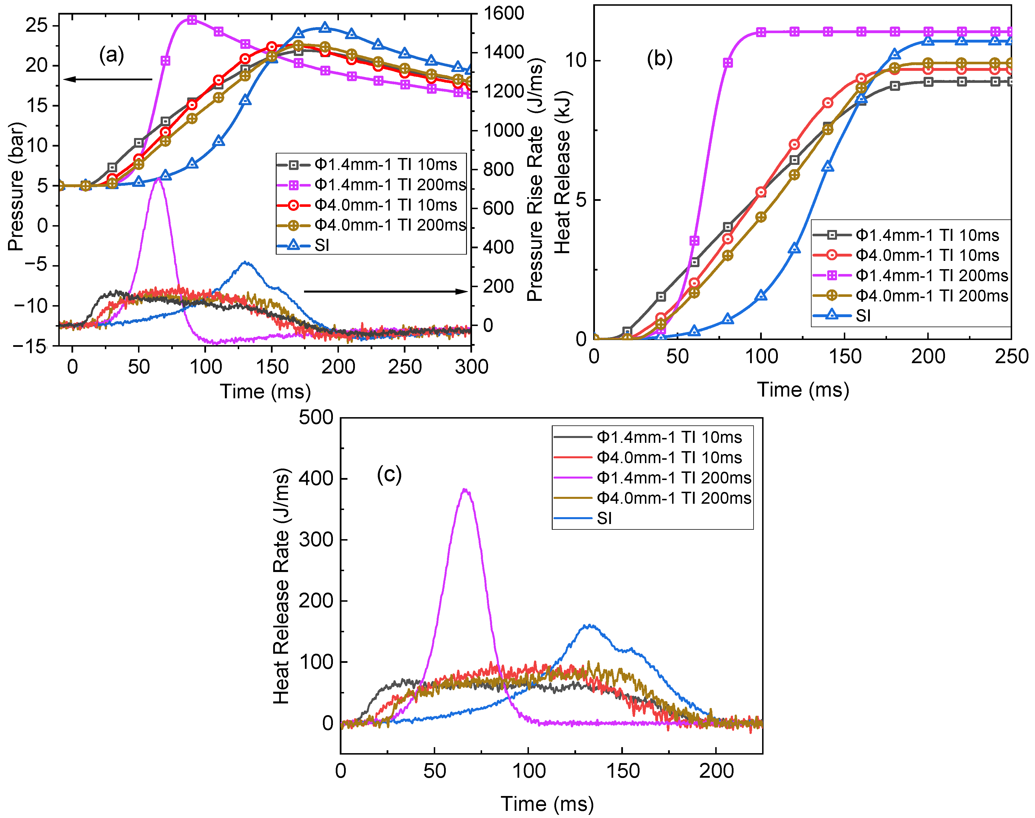
Figure 2 illustrates the effects of different orifice diameters of single-orifice pre-chambers on the combustion characteristics of TJ-PSI mode with various TI values. The results are compared to those of the SI mode. All experiments are conducted at the same initial conditions (φ = 1.0, T0 = 393 ± 5 K, p0 = 5 bar). As shown in Figure 2a, for the pre-chamber with a single Φ4 mm orifice, TI varying from 10 ms to 200 ms has minimal impact on the pressure and heat release in the main chamber, indicating that the ignition event in the main chamber has little impact on the overall combustion dynamics. This is because the throttling effect of a large orifice diameter (Φ4 mm in this experiment) is weaker compared to a smaller orifice, significantly reducing the dissipation of thermal and kinetic energy when the jet flows through the pre-chamber orifice, thereby forming the turbulent jet ignition (TJI) mode [21]. In contrast, for pre-chamber with a single Φ1.4 mm orifice, the smaller diameter enhances the throttling effect during ejection, leading to excessive turbulence. This increased turbulence causes jet flame quenching, resulting in a flameless turbulent jet [21]. Consequently, the ignition of the mixture in the main chamber is primarily controlled by the spark plug in the main chamber, and variations in TI significantly affect the combustion process by altering the turbulence intensity at the time of ignition. The discussion that follows focuses mainly on cases where TI = 10 ms and TI = 200 ms.

Figure 2.
Influence of orifice diameter on (a) pressure profiles and pressure rise rate, (b) total heat release, and (c) heat release rate under TJ-PSI mode at 5 bar with different time intervals (10 ms, 200 ms), compared to SI mode. The lines without symbols in subfigure (a) represent the calculated pressure rise rate with the arrows indicating the corresponding y-axis for the curves. Time zero denotes the timing of post-spark ignition in the main chamber.
As shown in Figure 2a, the main chamber pressure trace obtained with a single Φ4 mm orifice pre-chamber and a TI of 10 ms exhibits a significantly lower pressure rise rate and a lower peak pressure compared to the case with a single Φ1.4 mm orifice pre-chamber at TI = 200 ms. While with a TI of 10 ms, the single Φ1.4 mm orifice pre-chamber case exhibits a lower pressure rise rate and a lower peak pressure compared to the case with a single Φ4.0 mm orifice pre-chamber. This is mainly due to the following reason. Prior to the turbulent jet penetration, although ignition of the premixed fuel in the main chamber is achieved, the subsequent high turbulence intensity disrupts the combustion process, ultimately degrading combustion behavior in the main chamber [17]. In contrast, as shown in Figure 2a, when TI = 200 ms, the maximum pressure rise rate in the main chamber with the Φ1.4 mm orifice pre-chamber case is the highest, with the pressure trace reaching a peak pressure of approximately 25 bar, which is the highest among all tested conditions. This is because, by the time ignition occurs, the turbulent jet penetration has nearly completed and the intensity of the turbulence in the main chamber has been increased. The increased turbulence intensity promotes the early development of the flame kernel, enlarging its size and enhancing flame wrinkling, which accelerates the overall combustion process [17]. A comparison of Figure 2b,c reveals that the total heat release and peak heat release rate for the Φ1.4 mm orifice case at TI = 10 ms are significantly lower than those at TI = 200 ms. Specifically, the peak heat release rate at TI = 10 ms is approximately 100 J/ms, only one-fourth of the value observed at TI = 200 ms. For the Φ4 mm orifice group, the heat release behavior remains relatively consistent across different TI values and is slightly better than that of the Φ1.4 mm orifice group at TI = 10 ms. However, when TI > 100 ms, the total heat release of the Φ4 mm orifice group is approximately 10% lower. Additionally, as shown in Figure 2b,c, the heat release duration of the Φ1.4 mm orifice group is longer at shorter TI (e.g., 10 ms) but decreases significantly at longer TI (e.g., 200 ms). In contrast, the Φ4 mm orifice group maintains a relatively stable duration with less variation across different TIs. These results suggest that, under an appropriate TI value, the Φ1.4 mm orifice group operating in TJ-PSI mode achieves higher combustion efficiency and more intensive heat release. Conversely, the large orifice diameter facilitates TJI mode, and the small orifice diameter under TJ-PSI mode with proper TI value can significantly enhance ammonia combustion.
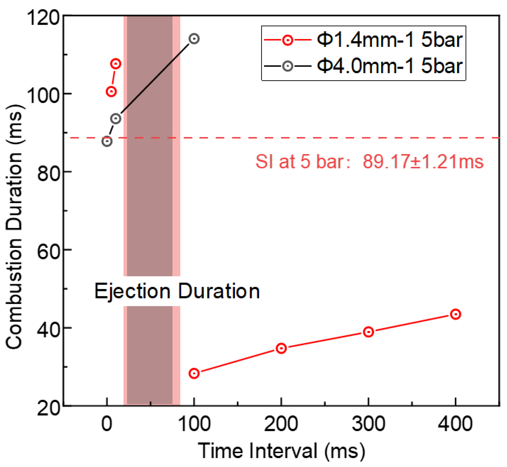
Figure 3 provides a more detailed comparison of the combustion duration in the main chamber for single-orifice pre-chambers with Φ1.4 mm and Φ4 mm orifices under varying TI values. Combustion duration represents the total heat release intensity in the main chamber. Given the same initial conditions, when the TI is around 10 ms, the Φ1.4 mm orifice group exhibits a relatively long heat release duration of about 110 ms, while the Φ4 mm orifice group shows a slightly shorter duration of about 94 ms at the same TI. In contrast, at TI = 100 ms, the Φ1.4 mm orifice group has the shortest heat release duration, around 30 ms, significantly lower than the previous two cases. When TI > 100 ms (after the jet ejection), the combustion duration for the Φ4 mm orifice case is nearly four times longer than that of the Φ1.4 mm orifice group. While the combustion duration for both cases increases primarily with TIs ranging from 0 ms to 100 ms for the Φ4 mm orifice group and from 100 ms to 400 ms for the Φ1.4 mm orifice group, the growth rate is notably higher for the Φ4 mm orifice group. Consequently, under TI > 100 ms, the total combustion intensity in the main chamber for the Φ4 mm orifice case is significantly lower than that of the Φ1.4 mm orifice case. During the ejection period (15–80 ms), the excessive turbulence intensity from the Φ1.4 mm orifice disrupts ignition in the main chamber. In contrast, the Φ4 mm orifice forms a jet flame capable of igniting the premixed mixture but still suffers from prolonged combustion duration and reduced heat release intensity. For the Φ1.4 mm orifice group with TI < 15 ms, since ignition in the main chamber occurs before jet ejection, the subsequent turbulent jet disrupts the combustion process, decreasing the heat release rate. Additionally, the larger pressure discrepancy established between the pre-chamber and the main chamber with the Φ1.4 mm orifice group leads to a higher penetration velocity and greater turbulence intensity in the main chamber, which extends the combustion duration compared to the Φ4 mm orifice group under the same TI conditions. This further supports the conclusions drawn earlier in the paper-when a small-orifice pre-chamber operating in TJ-PSI mode is used with insufficient TI, the combustion heat release intensity and performance may be inferior to those achieved in TJI mode (large orifice diameter conditions).

Figure 3.
The impact of the time interval on the combustion durations in TJ-PSI mode with varying orifice diameters (Φ1.4 mm × 1, Φ4 mm × 1) at 5 bar. The SI mode results are depicted as dashed lines for comparison. The red and black shaded areas indicate the jet ejection duration. Time zero on the axis marks the spark ignition timing in the pre-chamber.
In summary, the combustion performance of the small-diameter case applying TJ-PSI strategy under an appropriate TI value surpasses that of TJI mode. To enhance the combustion intensity and efficiency in the main chamber under TJ-PSI mode, a smaller pre-chamber orifice diameter and an appropriate TI value should be carefully selected.
4.2. The Influence of Pre-Chamber Orifice Number on the Combustion Characteristics of TJ-PSI Strategy
In addition to orifice diameter, the orifice number of the pre-chamber nozzle can significantly influence the pre-chamber jet characteristics as well [31]. This is primarily because the orifice number directly affects the total flow area and the interaction zone between the pre-chamber jet and the premixed mixture in the main chamber.
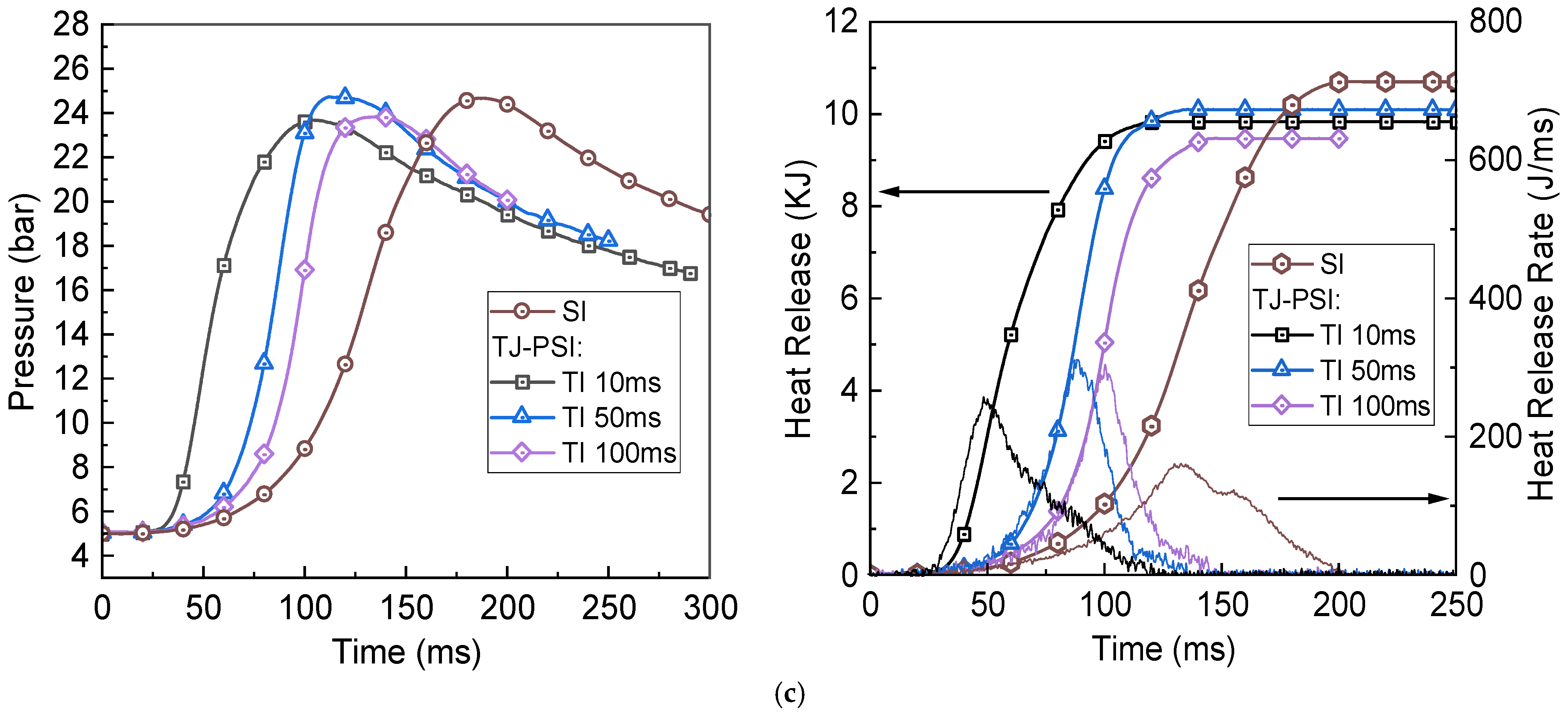
Figure 4 illustrates the combustion characteristics under TJ-PSI mode for pre-chambers with an orifice diameter of Φ1.4 mm and orifice numbers of 1, 4, and 6 (represented by Φ1.4 mm × 1, Φ1.4 mm × 4, Φ1.4 mm × 6), respectively. The experiments are performed under identical initial conditions (φ = 1.0, T0 = 393 ± 5 K, p0 = 5 bar). The pressure traces in Figure 4 show that both the four-orifice and six-orifice configurations in the TJ-PSI combustion mode achieve stable ignition and heat release within a TI range of 10–100 ms. In contrast, the single-orifice group requires a longer TI (at least 100 ms) to achieve comparable combustion performance to the multi-orifice groups in this experiment. Additionally, the peak pressure does not exhibit a strictly positive correlation with increasing orifice count. Specifically, when the orifice number increases from 1 to 4, the peak pressure rises by approximately 4% for TI ≥ 100 ms and by about 10% for TI values ranging from 0 to 10 ms. However, when the number of orifices increases from 4 to 6, there is a slight decline in peak pressure, which decreases by around 0–8% for TI values between 10 and 100 ms. A comparison of the heat release traces in Figure 4a–c demonstrates that increasing the number of orifices from 1 to 4 leads to higher total heat release and improved combustion efficiency for the same TI values, particularly under short TI conditions. However, further increasing the orifice number to 6 results in a decline in total heat release and combustion efficiency at longer TI values (50–100 ms in this experiment). Moreover, when TI is 10–100 ms, increasing the orifice number enhances the peak heat release rate, which results in more intense heat release process with short combustion duration. This phenomenon is especially pronounced under short TI values and for pre-chambers with fewer orifices. The primary reason is that a larger number of orifices expands the turbulence interaction region in the main chamber, rapidly enhancing the turbulence intensity of the premixed mixture. Meanwhile, the moderately intense jets enhance the interaction between the pre-chamber jet and the premixed mixture in the main chamber, promoting efficient turbulent mixing and accelerating flame kernel development. This controlled level of turbulence prevents excessive disturbance to the ignition kernel. Consequently, the risk of turbulence-induced quenching is reduced, and a higher peak combustion rate is achieved. Overall, Figure 4 indicates that for the Φ1.4 mm orifice pre-chamber group in this study, as the orifice number increases, the pressure, heat release, and heat release rate traces for different TI values tend to converge under short TI conditions (TI < 100 ms), indicating a reduced sensitivity to ignition timing. This suggests that the influence of TI on combustion performance in the main chamber diminishes as the number of orifices increases (from 1 to 6 in this experiment). This is because a multi-orifice configuration rapidly enhances the intensity of turbulence in the main chamber, mitigates the adverse effects of turbulence-induced ignition kernel quenching, and significantly improves combustion performance. As a result, for the multi-orifice group, the combustion performance in the main chamber becomes consistent and relatively superior under various short TI conditions.
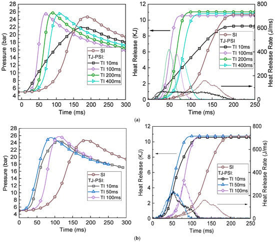

Figure 4.
Influence of orifice number on pressure profiles, total heat output, rate of heat release in TJ-PSI mode at 5 bar with different time intervals, compared to SI mode. The three plots on the right side show the total heat release and heat release rate curves, where the lines without symbols represent the heat release rate. Arrows in the right-hand plots indicate the corresponding y-axis for the curves. Time zero represents the point of post-spark ignition in the main chamber. (a) Φ1.4 mm × 1; (b) Φ1.4 mm × 4; (c) Φ1.4 mm × 6.
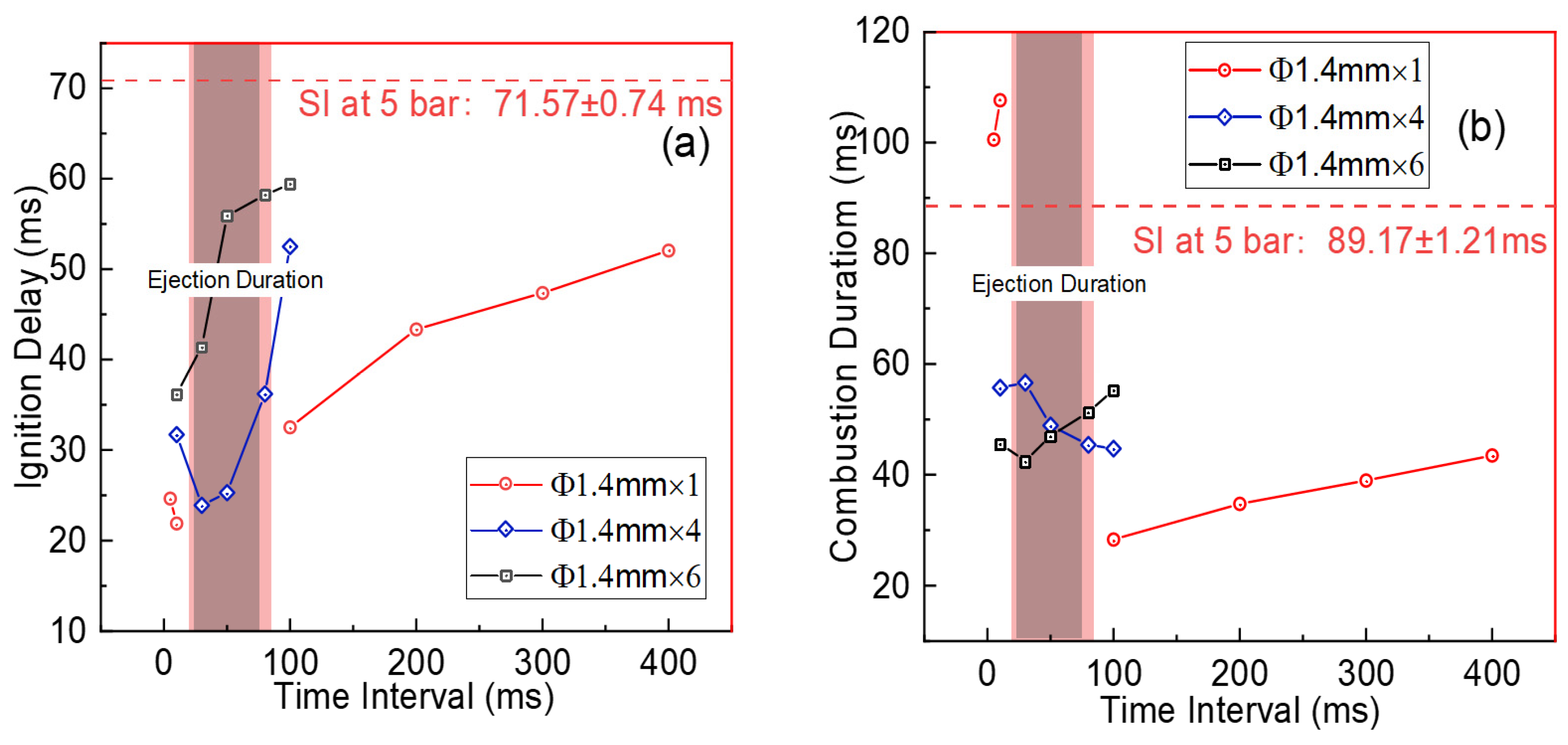
Figure 5 further illustrates the ignition delay and combustion duration of the premixed fuel in the main chamber under different TI values for pre-chambers with varying orifice numbers (Φ1.4 mm) under identical initial conditions (φ = 1.0, T0 = 393 ± 5 K, p0 = 5 bar). The ignition delay represents the early development of the flame kernel, while the combustion duration reflects the total heat release intensity in the main chamber. From Figure 5, during the jet ejection period (10–100 ms), the single-orifice pre-chamber often fails to achieve stable ignition due to turbulence-induced kernel quenching. In contrast, the multi-orifice pre-chamber effectively mitigates this issue, achieving stable ignition and heat release. As illustrated in Figure 5a, for the same ignition delay, the TI value required for the multi-orifice pre-chamber is only about 20% of that for the single-orifice pre-chamber. This indicates that a multi-orifice pre-chamber structure significantly alleviates the ignition kernel quenching problem under short TI conditions, thereby reducing the necessary TI value for the same ignition delay. This highlights the advantage of multi-orifice configurations in facilitating rapid establishment of a flow field with suitable turbulence intensity for flame kernel development. However, it is also noteworthy that within the TI range selected for this study (0 ms < TI < 100 ms), the ignition delay for the Φ1.4 mm × 4 case is consistently shorter than that of the Φ1.4 mm × 6 case. Moreover, as TI increases, the ignition delay of the Φ1.4 mm × 4 case initially decreases and then significantly increases, whereas the ignition delay of the Φ1.4 mm × 6 case keeps increasing from a minimum of 36 ms. Figure 5b reveals that for the same combustion duration, the TI values required for the multi-orifice pre-chamber are considerably lower than those for the single-orifice pre-chamber. For the Φ1.4 mm × 4 configuration, the combustion duration decreases with increasing TI and reaches a minimum of 45 ms at approximately TI = 100 ms, whereas the Φ1.4 mm × 6 pre-chamber shows the opposite trend, with its combustion duration first decreasing and then increasing with increasing TI, and reaches the shortest combustion duration of 41 ms around TI = 30 ms. Although the multi-orifice pre-chamber gives rise to a less pronounced reduction in combustion duration compared to the single-orifice configuration, it significantly lowers the TI value required to achieve the same total heat release. Consequently, the total combustion duration, from pre-chamber spark to the end of main chamber combustion, can be substantially shortened.

Figure 5.
The relationship between the time interval, ignition delay (a), and combustion duration (b) in TJ-PSI mode with a 1.4 mm orifice diameter and varying orifice number at 5 bar. The SI mode results are depicted as dashed lines for comparison. Time zero on the axis marks the spark ignition timing in the pre-chamber.
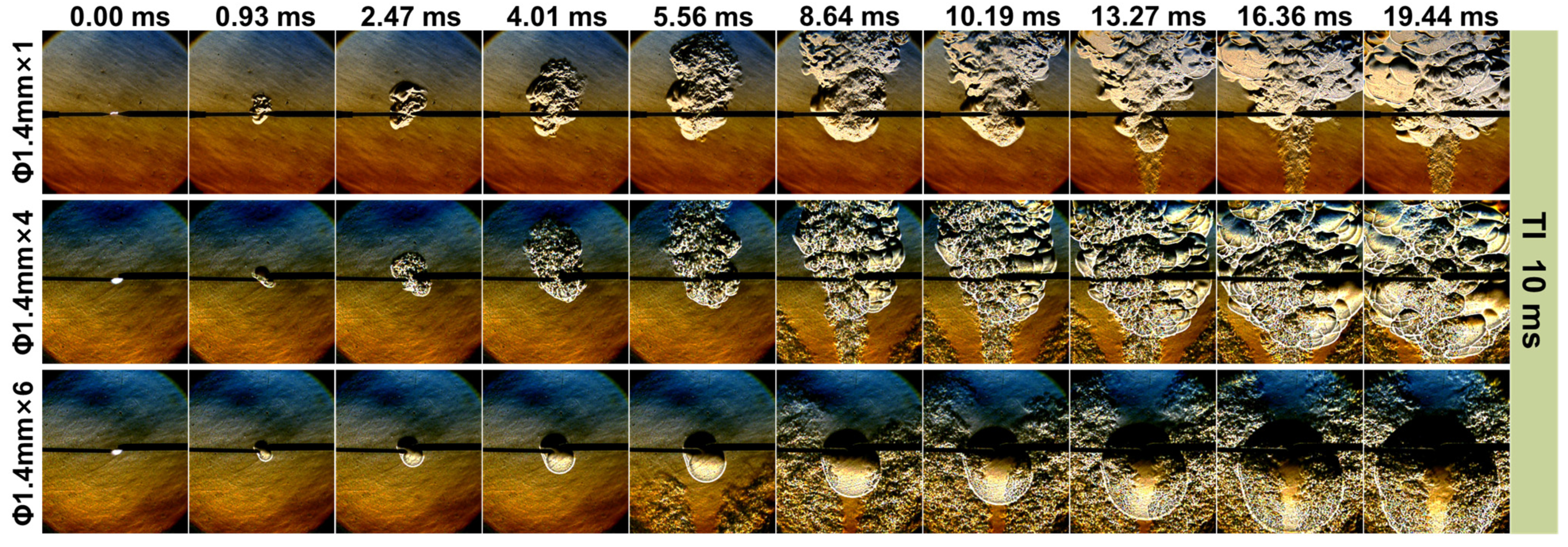
To gain deeper insight into the intrinsic mechanism by which the pre-chamber orifice number influences the turbulent jet and consequently the combustion process, the recorded flame kernel development in the main chamber is analyzed. Figure 6 presents a series of images illustrating the flame kernel development for three experimental groups with an identical orifice diameter of 1.4 mm but different orifice numbers of 1, 4, and 6, respectively, at TI = 10 ms. It is evident that under the same experimental conditions (φ = 1.0, T0 = 393 ± 5 K, p0 = 5 bar, TI = 10 ms), the flame kernel propagation in the early ignition stage is the fastest for the Φ1.4 mm × 4 configuration, while the Φ1.4 mm × 6 case shows faster propagation than the single-orifice case. It is worth noting that Figure 6 illustrates solely the initial phase of flame spread, because the maximum time displayed remains below the ignition delay, which is referred to as the timing corresponding to 5% of the total heat release.

Figure 6.
The influence of orifice count on the development of the flame kernel in TJ-PSI mode at 5 bar with a TI of 10 ms. The orifice number and diameter for each experimental group are indicated on the left side of the figure, while the timing of each flame image is labeled at the top. The jet is directed vertically from the bottom upwards.
Under the TJ-PSI mode with a TI of 10 ms, the single-orifice configuration exhibits a relatively smooth spherical ignition kernel at the early stages of 0.93 ms and 2.47 ms. The underlying reason is that, following spark ignition, the pre-chamber mixture needs a finite ejection time before emerging from the nozzle, which prevents the jet from contributing to the combustion process at such early timings. Subsequently, the flame kernel expands rapidly, and wrinkles appear on its surface. Up to 10.19 ms, the absence of any observable shadow in the area upstream of the pre-chamber jet flow indicates that the flame kernel is primarily governed by the interaction with the cold jet [17,32]. The cold jet, characterized by comparatively low temperature and velocity, infiltrates the spherical flame kernel and introduces turbulent disturbances together with unreacted mixture. This leads to a pronounced expansion of the flame kernel along the vertical direction. Consequently, some irregular edges together with sophisticated cellular structures appear on the upper half of the flame kernel.
At 13.27 ms, the hot jet becomes evident at the bottom of the flame kernel image for the single-orifice case. Concurrently, the spherical flame in the lower region exhibits a gradual contraction, which can be ascribed to the ultra-high velocity and intense turbulence of the hot jet. These factors disrupt the flame front structure, ultimately leading to local extinction [33,34]. This observation elucidates why the single-orifice configuration is prone to misfire and incapable of sustaining stable ignition during post-ignition at short TI values (i.e., within the jet ejection period).
For the Φ1.4 mm × 4 and Φ1.4 mm × 6 configurations at TI = 10 ms, Figure 6 shows that the spherical flame in the lower region does not undergo contraction. This behavior can be attributed to the larger number of orifices compared with the single-orifice case, which increases the total flow area, allowing multiple jets of mixture to be simultaneously ejected from the pre-chamber. These jets collectively interact with the premixed mixture in the main chamber, substantially enlarging the interaction region between the pre-chamber jets and the gas mixture of ammonia/‘air’. As a result, the intensity of turbulence in the main chamber is significantly enhanced within a shorter timescale compared to the single-orifice case. This facilitates the prompt establishment of a flow field with suitable turbulence intensity for flame kernel development. Such moderately intensified jets mitigate the risk of turbulence-induced ignition kernel quenching, markedly improve combustion characteristics, and consequently achieve superior ignition performance.
In addition, Figure 6 clearly demonstrates that the ignition kernel of the Φ1.4 mm × 4 configuration propagates more rapidly than of the Φ1.4 mm × 6 configuration. A critical factor is that the turbulence intensity established in the main chamber is consistently higher in the Φ1.4 mm × 4 case than in the Φ1.4 mm × 6 case at the same timing [35]. The larger number of orifices excessively increases the total flow area of the pre-chamber, which reduces the pressure differential established between the pre-chamber and the main chamber. As a result, the jet velocity decreases, resulting in weaker turbulence intensity in the main chamber of the six-orifice case compared with the four-orifice case. This consequently causes the flow field to develop more slowly and limits its capability to enhance combustion under the TJ-PSI mode. This factor accounts for the slower ignition kernel propagation and the comparatively inferior combustion performance observed in the Φ1.4 mm × 6 configuration relative to the Φ1.4 mm × 4 case.
In summary, increasing the number of pre-chamber orifices can effectively mitigate turbulence-induced ignition kernel quenching, reduce the necessary TI value, and enhance combustion efficiency. However, further increasing the orifice number does not necessarily lead to improved combustion performance. For instance, under the conditions of this experiment, increasing the orifice number from 1 to 4 can significantly optimize combustion performance. However, further increasing it to 6 leads to a decline in certain combustion characteristics. Therefore, in practical applications, a balanced consideration of various pre-chamber parameters is crucial for achieving optimal ignition and combustion performance.
5. Conclusions
This study experimentally evaluates the impact of orifice diameter and orifice number on the enhancement of the premixed ammonia/air combustion under TJ-PSI strategy. Main combustion characteristics, such as pressure, heat release, ignition delay, and combustion duration, are compared between different pre-chamber configurations. Additionally, Schlieren images of experiments with varying single-orifice diameters are analyzed to further illustrate the impact of orifice diameter.
Regarding the influence of pre-chamber orifice diameter, the study finds that an excessively large pre-chamber orifice diameter (e.g., 4 mm) results in TJI mode, where combustion performance is poor and less sensitive to TI variations. In contrast, smaller pre-chamber orifice diameters (e.g., 1.4 mm) significantly improve fuel combustion performance under appropriate TI. Moreover, the study demonstrates that increasing the number of orifices appropriately improves the interplay of the pre-chamber jet with the main chamber mixture, thereby enhancing combustion performance, especially under short TI conditions. Using a four-orifice configuration significantly optimizes combustion performance, and mitigates flame kernel extinction with short TIs. Consequently, the total combustion duration from pre-chamber spark to the end of main chamber combustion can be significantly shortened, thereby enhancing the feasibility of the TJ-PSI strategy for internal combustion engine applications. However, excessive orifice numbers (e.g., six orifices) can degrade combustion performance in the main chamber due to greater heat loss, reduced turbulence temperature, and intensity. Therefore, achieving optimal combustion enhancement under the TJ-PSI strategy requires careful balancing of orifice diameter, orifice number, and TI, tailored to specific operating conditions.
Supplementary Materials
The following supporting information can be downloaded at: https://www.mdpi.com/article/10.3390/en18215659/s1.
Author Contributions
Conceptualization, S.D. and Z.W.; methodology, R.L. and H.W.; formal analysis, Y.G., X.Z. and J.Z.; investigation, Y.G. and X.Z.; resources, Z.W.; data curation, R.L., X.Z. and Y.C.; writing—original draft preparation, Y.G.; writing—review and editing, S.D.; supervision, S.D.; project administration, Z.W.; funding acquisition, Z.W. All authors have read and agreed to the published version of the manuscript.
Funding
This research was funded by the project of Combustion and Emission Control Technologies Research for Ammonia-fueled Marine Engines based on the Diesel Cycle.
Data Availability Statement
The original contributions presented in this study are included in the article/Supplementary Material. Further inquiries can be directed to the corresponding author.
Conflicts of Interest
The authors declare no conflicts of interest.
Abbreviations
| TJ-PSI | Turbulent Jet-post Spark Ignition |
| TI | Time Interval |
| TJI | Turbulent Jet Ignition |
| SI | Spark Ignition |
| CVV | Constant Volume Vessel |
| dQ | heat release rate |
| φ | Pre-mixed gas fuel-air equivalence ratio |
| T0 | Initial temperature |
| P0 | Initial pressure |
References
- Valera-Medina, A.; Amer-Hatem, F.; Azad, A.K.; Dedoussi, I.C.; De Joannon, M.; Fernandes, R.X.; Glarborg, P.; Hashemi, H.; He, X.; Mashruk, S.; et al. Review on Ammonia as a Potential Fuel: From Synthesis to Economics. Energy Fuels 2021, 35, 6964–7029. [Google Scholar] [CrossRef]
- Kumar, P.; Meyer, T.R. Experimental and Modeling Study of Chemical-Kinetics Mechanisms for H2-NH3-Air Mixtures in Laminar Premixed Jet Flames. Fuel 2013, 108, 166–176. [Google Scholar] [CrossRef]
- Zhang, Z.; Li, T.; Chen, R.; Wang, N.; Wei, Y.; Wu, D. Injection Characteristics and Fuel-Air Mixing Process of Ammonia Jets in a Constant Volume Vessel. Fuel 2021, 304, 121408. [Google Scholar] [CrossRef]
- Ryu, K.; Zacharakis-Jutz, G.E.; Kong, S.C. Effects of Gaseous Ammonia Direct Injection on Performance Characteristics of a Spark-Ignition Engine. Appl. Energy 2014, 116, 206–215. [Google Scholar] [CrossRef]
- Dimitriou, P.; Javaid, R. A Review of Ammonia as a Compression Ignition Engine Fuel. Int. J. Hydrogen Energy 2020, 45, 7098–7118. [Google Scholar] [CrossRef]
- Berwal, P.; Kumar, S.; Khandelwal, B. A Comprehensive Review on Synthesis, Chemical Kinetics, and Practical Application of Ammonia as Future Fuel for Combustion. J. Energy Inst. 2021, 99, 273–298. [Google Scholar] [CrossRef]
- Kurien, C.; Mittal, M. Review on the Production and Utilization of Green Ammonia as an Alternate Fuel in Dual-Fuel Compression Ignition Engines. Energy Convers. Manag. 2022, 251, 114990. [Google Scholar] [CrossRef]
- Ma, F.; Guo, L.; Li, Z.; Zeng, X.; Zheng, Z.; Li, W.; Zhao, F.; Yu, W. A Review of Current Advances in Ammonia Combustion from the Fundamentals to Applications in Internal Combustion Engines. Energies 2023, 16, 6304. [Google Scholar] [CrossRef]
- Tornatore, C.; Marchitto, L.; Sabia, P.; De Joannon, M. Ammonia as Green Fuel in Internal Combustion Engines: State-of-the-Art and Future Perspectives. Front. Mech. Eng. 2022, 8, 944201. [Google Scholar] [CrossRef]
- Zhao, Z.; Qi, Y.; Cai, K. Research on the combustion mechanism of plasma-induced ammonia-hydrogen jet ignition engine. Int. J. Hydrogen Energy 2024, 65, 398–409. [Google Scholar] [CrossRef]
- D’Antuono, G.; Lanni, D.; Galloni, E.; Fontana, G. Numerical Analysis of the Combustion Process in a Pre-Chamber Marine Engine Fueled with Ammonia-Hydrogen Mixtures. In Proceedings of the 17th International Conference on Engines and Vehicles, Capri, Italy, 14–17 September 2025; SAE Technical Paper, No. 2025-24-0021. SAE: Warrendale, PA, USA, 2025. [Google Scholar] [CrossRef]
- Yang, X.; Li, G.; Wang, P.; Cheng, Y.; Zhao, Y. Numerical Investigation of the Operating Characteristics of the Passive and Active Prechamber Jet Ignition in a Natural Gas Engine. ACS Omega 2024, 9, 31933–31945. [Google Scholar] [CrossRef]
- Rajasegar, R.; Niki, Y.; García-Oliver, J.M.; Li, Z.; Musculus, M.P.B. Fundamental Insights on Ignition and Combustion of Natural Gas in an Active Fueled Pre-Chamber Spark-Ignition System. Combust. Flame 2021, 232, 111561. [Google Scholar] [CrossRef]
- Qiang, Y.; Jin, K.; Zhao, S.; Cai, J.; Su, F.; Wang, S.; Ji, C. Optimization of Power Performance and Combustion Stability of Ultra-Lean Combustion in Hydrogen Fuel Engines through Combined Turbulent Jet Ignition and Variable Valve Timing. Fuel 2025, 381, 133493. [Google Scholar] [CrossRef]
- Zhu, S.; Akehurst, S.; Lewis, A.; Yuan, H. A Review of the Pre-Chamber Ignition System Applied on Future Low-Carbon Spark Ignition Engines. Renew. Sustain. Energy Rev. 2022, 154, 111872. [Google Scholar] [CrossRef]
- Biswas, S.; Tanvir, S.; Wang, H.; Qiao, L. On Ignition Mechanisms of Premixed CH4/Air and H2/Air Using a Hot Turbulent Jet Generated by Pre-Chamber Combustion. Appl. Therm. Eng. 2016, 106, 925–937. [Google Scholar] [CrossRef]
- Wu, H.; Li, R.; Dong, S.; Deman, Z.; Xu, J.; Wang, Z. Enhancing Ammonia Combustion Using Pre-Chamber Turbulent Jet Combined with Post Spark Ignition Strategy. Fuel 2024, 371, 131979. [Google Scholar] [CrossRef]
- Yan, B.; Waters, B.; Haines, A.; McGhee, M.; Hu, T.; Deng, W.; Pu, Y.; Ma, T. Experimental Study for Effect of Multi-Site Spark Ignition on Dedicated Hybrid Engine Performance under High Dilution Condition. J. Therm. Sci. 2024, 34, 254–267. [Google Scholar] [CrossRef]
- Feng, Z.; Zhou, L.; Liu, P.; Gao, Q.; Li, K.; Wei, H. Effect of Turbulent Jet Ignition Based on Different Pre-Chamber Structures on the Combustion Characteristics of Methane Fuel. Chin. Intern. Combust. Engine Eng. 2021, 42, 23–28, 35. [Google Scholar]
- Hua, J.; Zhou, L.; Gao, Q.; Feng, Z.; Wei, H. Influence of Pre-Chamber Structure and Injection Parameters on Engine Performance and Combustion Characteristics in a Turbulent Jet Ignition (TJI) Engine. Fuel 2021, 283, 119236. [Google Scholar] [CrossRef]
- Cui, Z.; Tian, J.; Zhang, X.; Yin, S.; Long, W.; Song, H. Experimental Study of the Effects of Pre-Chamber Geometry on the Combustion Characteristics of an Ammonia/Air Pre-Mixture Ignited by a Jet Flame. Processes 2022, 10, 2102. [Google Scholar] [CrossRef]
- Tang, Q.; Sampath, R.; Sharma, P.; Echeverri, M.; Cenker, E.; Magnotti, G. Study on the Effects of Narrow-Throat Pre-Chamber Geometry on the Pre-Chamber Jet Velocity Using Dual Formaldehyde PLIF Imaging. Combust. Flame 2022, 240, 111987. [Google Scholar] [CrossRef]
- Huang, L.; Tang, Q.; Sun, J.; Yao, M. Study on the Effects of Nozzle Layouts of the Passive Pre-Chamber on Jet and Combustion Characteristics. J. Eng. Thermophys. 2024, 45, 2531–2539. [Google Scholar]
- Wang, B.; Xie, F.; Hong, W.; Du, J.; Chen, H.; Su, Y. The Effect of Structural Parameters of Pre-Chamber with Turbulent Jet Ignition System on Combustion Characteristics of Methanol-Air Pre-Mixture. Energy Convers. Manag. 2022, 274, 116473. [Google Scholar] [CrossRef]
- Yang, J.; Xie, F.; Jiang, B.; Li, X.; Su, Y.; Zhang, H. Influence of Structure Parameters of Pre-Chamber on Lean Combustion of Active Pre-Chamber Jet Ignition Engine. Energy 2024, 304, 132053. [Google Scholar] [CrossRef]
- Xie, F.; Wang, J.; Dou, H.; Li, J.; Wang, B.; Hong, W. Influence of Structural Parameters of Pre-Combustion Chamber on the Development Characteristics of Gasoline Hot Jet. Automot. Eng. 2022, 44, 1716–1724. [Google Scholar] [CrossRef]
- Tomić, R.; Sjerić, M.; Krajnović, J.; Ugrinić, S. Influence of Pre-Chamber Volume, Orifice Diameter and Orifice Number on Performance of Pre-Chamber SI Engine—An Experimental and Numerical Study. Energies 2023, 16, 2884. [Google Scholar] [CrossRef]
- Li, F.; Zhao, Z.; Wang, Z.; Wang, B. Experimental and numerical study of a methane-fueled pre-chamber system in rapid compression machine. Combust. Sci. Technol. 2021, 193, 1463–1494. [Google Scholar] [CrossRef]
- Lapuerta, M.; Sanz-Argent, J.; Raine, R. Heat Release Determination in a Constant Volume Combustion Chamber from the Instantaneous Cylinder Pressure. Appl. Therm. Eng. 2014, 63, 520–527. [Google Scholar] [CrossRef]
- Woschni, G. A Universally Applicable Equation for the Instantaneous Heat Transfer Coefficient in the Internal Combustion Engine. SAE Trans. 1968, 76, 3065–3083. [Google Scholar] [CrossRef]
- Zhou, L.; Song, Y.; Hua, J.; Liu, F.; Liu, Z.; Wei, H. Effects of Different Hole Structures of Pre-Chamber with Turbulent Jet Ignition on the Flame Propagation and Lean Combustion Performance of a Single-Cylinder Engine. Fuel 2022, 308, 121902. [Google Scholar] [CrossRef]
- Wei, F.; Lu, M.; Long, W.; Dong, D.; Dong, P.; Xiao, G.; Tian, J.; Tian, H.; Wang, P. Optical Experiment Study on Ammonia/Methanol Mixture Combustion Performance Induced by Methanol Jet Ignition in a Constant Volume Combustion Bomb. Fuel 2023, 352, 129090. [Google Scholar] [CrossRef]
- Mueller, C.; Driscoll, J.; Reuss, D.; Drake, M. Effects of unsteady stretch on the strength of a freely-propagating flame wrinkled by a vortex. Symp. Int. Combust. 1996, 26, 347–355. [Google Scholar] [CrossRef]
- Sayama, S.; Kinoshita, M.; Mandokoro, Y.; Fuyuto, T. Spark ignition and early flame development of lean mixtures under high-velocity flow conditions: An experimental study. Int. J. Engine Res. 2019, 20, 236–246. [Google Scholar] [CrossRef]
- Mathpatii, C.S.; Tabib, M.V.; Deshpande, S.S.; Joshi, J.B. Dynamics of Flow Structures and Transport Phenomena, 2. Relationship with Design Objectives and Design Optimization. Ind. Eng. Chem. Res. 2009, 48, 8285–8311. [Google Scholar] [CrossRef]
Disclaimer/Publisher’s Note: The statements, opinions and data contained in all publications are solely those of the individual author(s) and contributor(s) and not of MDPI and/or the editor(s). MDPI and/or the editor(s) disclaim responsibility for any injury to people or property resulting from any ideas, methods, instructions or products referred to in the content. |
© 2025 by the authors. Licensee MDPI, Basel, Switzerland. This article is an open access article distributed under the terms and conditions of the Creative Commons Attribution (CC BY) license (https://creativecommons.org/licenses/by/4.0/).

