Abstract
The paper presents select in situ and numerical investigations related to improving the energy efficiency of historic buildings. Using the case study of a historic timber building as an example, the procedure of the in situ investigation of its existing condition is presented. This procedure included measuring the moisture of the timber elements, determining the presence of fungi, mold, and wood-destroying insects, infrared camera inspection, and measuring the microclimate of the rooms. According to the conclusions of the building survey report, conservation guidelines were proposed. On the basis of those proposed guidelines, thermal upgrades were suggested, including insulation on the inside of the envelope components. Detailed numerical calculations were provided for the proposed thermal insulation systems. Those included a hygrothermal performance evaluation in the context of the change in the moisture content of timber elements in the insulated envelope components. The risk of mold development on the surface of selected junctions was also estimated. The key outcome of this study is a proprietary procedure for improving the thermal protection quality of envelope components of historic timber buildings.
1. Introduction
Historic buildings are a key part of cultural heritage, valued for both material and identity reasons [1,2,3,4,5]. The current EU climate policy [6] and the New European Bauhaus framework [7] pose major challenges for their renovation and the goal of climate-neutral cities. Residential buildings consume 40% of total energy, with 75% still inefficient [8]. The EU aims to achieve a low-carbon building stock by 2050. About 14% of EU buildings were built before 1919 and 12% between 1919 and 1945, accounting for 18% of sectoral emissions [9,10,11,12,13].
Although EU energy standards do not apply to protected historic structures [8], owners seek efficiency improvements due to high operating costs [14,15,16]. The Building Performance Institute [17] notes that moderate upgrades can reduce emissions without harming heritage. Mazzarella [18] stresses the lack of standardized procedures for sustainable retrofitting while preserving cultural value. Environmental certification and sustainability assessment methods are also gaining importance [19]. De Santoli [20] argues that energy upgrades should serve heritage protection rather than conflict with conservation goals.
The European Standard EN 16883:2017 [21] introduced a structured, interdisciplinary process for historic building modernization [22,23]. While non-prescriptive, its iterative approach is difficult to apply to smaller projects. Numerous studies address the energy upgrading of historic buildings [24,25,26,27,28,29,30,31,32].
Hansen [33,34] examined the hygrothermal performance of internally insulated masonry using experimental and numerical methods. Zagorskas et al. [35] analyzed moisture problems in brick walls and optimal insulation selection. Orlik-Kożdoń et al. [36,37,38] discussed risks such as increased moisture, biological corrosion, and mold, proposing a procedure tested on a historic tenement in Lviv. Ma et al. [39] reviewed retrofitting methods, noting that while insulation and HVAC upgrades improve efficiency, the best solutions depend on economic and environmental factors.
Feodrczak-Cisak [40] described diagnostic investigations for historic timber buildings. Seong Jin Chang [41] showed that insulation layout and climate affect hygrothermal performance, while Staněk et al. [42] highlighted degradation and biocorrosion risks in timber structures. Studies have also explored integrating solar systems into historic buildings [43,44,45,46].
Methodologically, Ascione et al. [9,10] proposed a multi-criteria retrofit approach. Franco et al. [47] suggested general guidelines considering heritage constraints, while Asadi et al. [48] developed an optimization model using genetic algorithms and neural networks. Penna et al. [49] analyzed reference buildings to determine optimal solutions balancing cost, efficiency, and comfort.
The reviewed literature highlights several issues that require further research (Table 1).

Table 1.
Recommendations and directions for further research.
They (Table 1) fail to address several critical aspects that, in the authors’ opinion, warrant particular attention:
- The absence of a formal requirement to archive comprehensive documentation of the architectural and structural characteristics of regional buildings;
- The lack of a mandatory procedure for the periodic verification of thermal modernization outcomes;
- The absence of clearly defined guidelines for the long-term operation and maintenance of buildings subjected to internal thermal retrofitting.
Systematic archiving of architectural and technical documentation would significantly facilitate future conservation and renovation efforts. A single verification process, as outlined in [EN 16883], may be insufficient due to the natural aging of materials, evolving functional requirements, and potential changes in building use. Clearly formulated guidelines for investors and practitioners could help prevent or mitigate the adverse effects of inappropriate or uninformed interventions on heritage structures.
The purpose of this study is therefore twofold:
- To present an effective methodology for enhancing the energy performance of a building while preserving its regional and cultural value, using a historic wooden structure located in the Silesian Beskids as a case study;
- To adapt the existing testing procedure [21] to the specific environmental and cultural conditions of the regional context.
2. Materials and Methods
2.1. Object of the Study
The subject of this study is a historic residential timber building, one of the few preserved examples of wooden architecture in the Silesian Beskids region of Poland. Since the late 19th century, the characteristic features of this architectural style have gradually disappeared due to numerous transformations and conversions. Currently, the largest concentration of timber buildings can be found in the center of Istebna and on the hills surrounding the town of Wisła in southern Poland.
The analyzed building dates back to the early 20th century and is located in Wisła-Malinka, one of the districts of Wisła. It exhibits construction and architectural solutions typical of local residential development, yet its functional layout differs from that of traditional highlander dwellings in the region. Residential houses in this area usually have a symmetrical interior arrangement, with two main rooms located on opposite sides of the building. The central section between them typically contains a hall (vestibule) and additional spaces such as a kitchen or a closet.
The building examined in this study does not have a symmetrical ground-floor layout (Figure 1). The entrance hall provides direct access to the kitchen, the living room, and a small bathroom (which was presumably originally a spare room). The second room is accessed through the kitchen. The attic is symmetrical and divided into three rooms arranged around a central corridor (Figure 2). The unused sections of the attic are separated by wooden partitions, and the building also includes a partial basement.
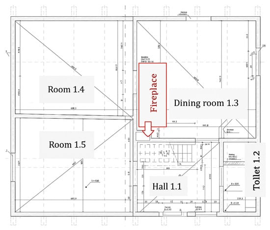
Figure 1.
Ground floor plan.
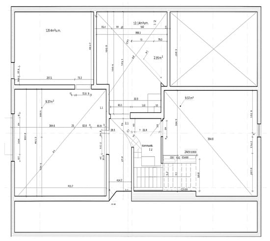
Figure 2.
Attic plan.
The building has a log-frame structure with varying wall thicknesses—the exterior walls are made of 20 cm thick logs, while the interior wall logs are 9 cm thick. The log-frame construction is typical of the Silesian Beskids region. Since the early 20th century, logs in such structures have been placed on a base course and dovetailed (“Dovetail”, also known as a swallowtail joint, is a typical woodwork joint, which in the Silesian Beskids was also known as “rybi chwast” (weed fish) [50]) at the corners. The number of logs depends on their size, but a typical wall consists of 9 to 11 logs. In some cases, the walls were covered with clapboards or protected against the weather with shingles or battens (The literature [51] of the subject describes batten as a small flat board, usually made with oak wood, often with rounded edges. A shingle, on the other hand, is a wooden wedge with a grove along its longer side or a flat board sharpened on one edge. Both terms were sometimes used interchangeably). In this building, the exterior wall is finished with 2 cm-thick battens, Figure 3, Figure 4, Figure 5, Figure 6 and Figure 7. The exterior surfaces are now covered with contemporary finishes—boards on laths in one room and fiberglass-reinforced lime plaster in the others.
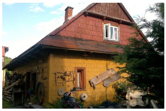
Figure 3.
Western and northern exterior walls.
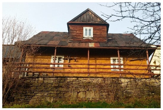
Figure 4.
Southern exterior wall.
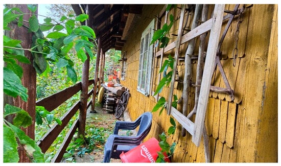
Figure 5.
Porch along the southern exterior wall.
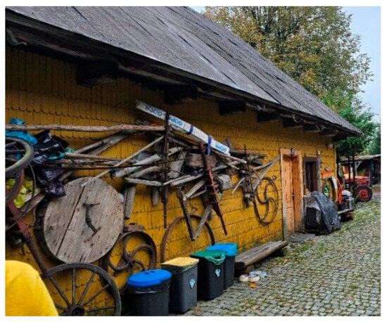
Figure 6.
Northern exterior wall.
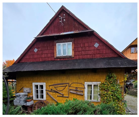
Figure 7.
Eastern exterior wall.
Another characteristic architectural feature typical of the Silesian Beskids is the front porch supported on the base course. It was usually located along the rear façade of the building, sometimes enclosed with additional walls or covered by a simple extension of the roof plane. The porch, known locally as płocina [50], served primarily as a storage space. The porch visible in Figure 4 and Figure 5 is equipped only with a wooden balustrade.
The beam-and-slab ceiling above the ground floor is finished with a wooden floor and features soffit forms on the underside. Historically, the house was thermally insulated with straw. The ceiling beams extend beyond the external wall face and support the beam carrying the rafters. This extension of the attic wall beyond the plane of the ground-floor wall, known as the cold end (Figure 8), is a regional architectural feature of the Silesian Beskids that is gradually disappearing.
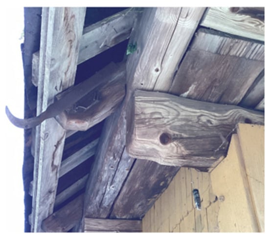
Figure 8.
Roof support extended outside the outer wall face, known as “cold end”; formed rafter tails and ceiling beam ends.
The house has a clasped purlin roof structure with preserved traditional carpentry joints. At present, the roof is covered with roofing felt.
The window joinery throughout the building is wooden, consisting of historic double windows with wooden frames and trims. Figure 9.
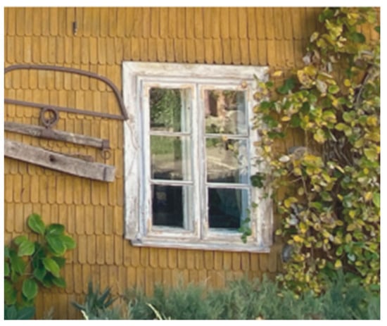
Figure 9.
Historic double window in batten exterior wall finish.
The architectural features of the building include a decorative gable with board and batten siding, wide eaves known as “przydaszki” (canopy roofs) [52], as well as formed rafter tails, ceiling beam ends, and window trims (Figure 8, Figure 9 and Figure 10).
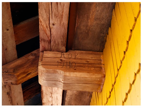
Figure 10.
Formed ceiling beam end.
2.2. Scope of Investigations
The investigations included the following:
- Historic in situ tests, on the basis of which the conservation guidelines were developed;
- Infrared camera inspection of the temperature field distribution of the interior and exterior surfaces of the envelope components;
- Identifying fungi and mold;
- Measuring timber moisture;
- Identifying damage caused by wood-destroying insects.
The research was limited by the accessibility of the building (private property), continuity of use, and protected regional features.
The conclusion of the study was the proposition of thermal upgrade improvements, related mainly to improving the thermal insulation quality of the building envelope.
2.2.1. Historic In Situ Investigations of the Timber Structure
The investigations included an analysis of the current condition of the building, with particular emphasis on identifying historic elements that should be preserved in their original form.
The analyzed house, known as Chata Paprocie (Fern Cottage), dates back to 1940, as indicated on the structural beam above the entrance (Figure 10). Chata Paprocie is located within the Silesian Beskids Landscape Park. According to the local development plan, the plot on which the house is situated is classified as a single-family residential area above 550 m AMSL. Both Chata Paprocie and the adjacent wooden barn are listed in the municipal register of monuments and are protected under separate legislation and regulations.
The scope of conservation includes the following [53]:
- The requirement to preserve the original shapes of buildings and structures, architectural details of the exterior wall finishes, traditional roof coverings, and roof forms.
- Permission to replace joinery in the buildings, provided that the original joinery forms and exterior wall finishes are maintained.
- Permission to remodel or convert the building to adapt it to contemporary standards, while preserving the features listed in item 1.
- Prohibition of thermal insulation of timber structures, as well as restrictions on finishing the front and side exterior walls of masonry buildings.
- Prohibition of installing technical devices (e.g., HVAC units, antennas, poles) in a manner that would compromise the visual integrity of the buildings.
- The requirement to preserve valuable mature trees and the original layout of structures on the property.
In accordance with the local development plan, the building’s shape, roof form, and existing eaves should be preserved. As evidenced on all exterior walls the building’s overall shape, roof form, and eaves—one of the most characteristic architectural features of the Silesian Beskids region—are well preserved. In particular, the roof structure remains in very good condition despite the absence of gutters and a functional drainage system, which is largely compensated by the extended eaves. The installation of gutters and a drainage system is recommended to protect the structure.
The exterior walls are clad with board-and-batten siding. Partial removal of this covering is recommended in order to assess the condition of the original log frame structure.
The building rests on a stone base course, most prominent on the southern side facing the escarpment, which serves as the structural foundation. The stones were laid without mortar and should remain unchanged as a testament to traditional masonry techniques. On the western exterior wall, cement mortar infills are present at the junction between the stone base course and the timber beams; these are considered unacceptable from both conservation and functional perspectives.
The original double-window joinery has been partially replaced with contemporary PVC windows. Some original windows remain and are preserved in good condition. The original door joinery is largely intact, with the exception of the newly installed bathroom door.
On the property, alongside the access road, there are clusters of valuable mature trees that complement the surroundings of the historic dwelling.
2.2.2. Infrared Camera Diagnostics
The temperature field distribution on the surfaces of the wall systems was measured remotely using an FLIR E8 infrared camera with the following specifications: thermal sensitivity: 0.06 °C; resolution: 320 × 240; range: from (−20 °C) to 250 °C; field of view: 45° × 34°. The infrared camera examinations were conducted at exterior air temperature Te = (10.2 °C), interior temperature 30.2 °C, and assumed surface emissivity ε = 0.9. The measurements were taken on 11 October at approximately 11:00 A.M. The measurements were carried out in accordance with the provisions of the ISO 9869 standard [54].
The purpose of the examination was to visualize the temperature field on the exterior and interior surfaces of the building, and to determine potential anomalies and thermal disruption sites.
The infrared camera diagnostics also included the parameters of the room microclimates, which were monitored at 1 h intervals during the study period from October to December 2024.
The thermograms (Figure 11 and Figure 12) show the colored visualization of the temperature field and its graphic form for selected envelope components and the junction, i.e., the following components:
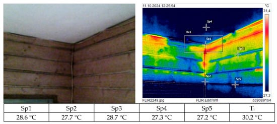
Figure 11.
Photograph and thermogram of the corner in room 1.3.
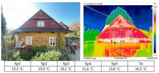
Figure 12.
Photograph and thermogram of the eastern exterior wall of the building.
The analysis was complemented with diagrams illustrating the changes in the exterior and interior environment parameters over the course of the investigation and during the remainder of the study period—Figure 13, Figure 14 and Figure 15. The measurements were carried out using ST-171 microrecorders.
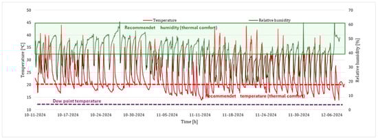
Figure 13.
Microclimate parameters in room 1.3.
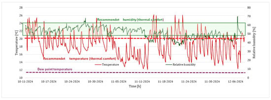
Figure 14.
The results of microclimate parameters measurement for room 1.4.
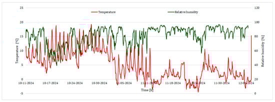
Figure 15.
Outside climate parameters.
The analysis of the thermogram and the results shown on the figures revealed disruptions in the temperature field distribution. On the outer wall, beam connections are clearly visible, arising from partial or complete lack of sealing of the beam joints. The temperature difference on the flat wall resulting from the inhomogeneities and disruptions is 1.5 °C. Also, significant local temperature drops were identified at the joint between the wall and the ceiling, which were probably caused partially by the lack of tightness in the joints of the timber structural elements, but mostly by the so-called cold end (Figure 8 and Figure 12).
Due to the local heat sources (fireplace) and the heat distribution method (gravity), the hygrothermal conditions in the room varied—Figure 13. Furthermore, considerable temperature fluctuations were observed, with momentary levels ranging from 40 °C to 15 °C. The air temperature does not exceed critical values (dew point temperature). However, it should be noted that the measurement was conducted in the central part of the room, and the distribution of measured parameters was not uniform throughout the room. It is suspected that temperature drops and relative humidity increases in the connection areas (e.g., corners).
Microclimate parameters were also measured in the adjacent room (1.4). The temperature fluctuations in that room were visibly smaller, i.e., from 25 °C to 12 °C. However, the periodic low temperatures reaching 12° are concerning. The building does not meet the thermal comfort standards.
The analysis of the thermogram and the results shown in Figure 12 and Figure 15 revealed significant differences in the temperature field distribution on the surface of the outer wall. The highest temperatures were observed at the timber ceiling (Sp2 = 15 °C), which suggests an increased heat flux and related loss of heat. This phenomenon is caused by lack of tightness in the joint and the fact that the attic is not heated and has no thermal insulation.
2.2.3. Evaluation of Timber Condition
As part of the evaluation of the timber condition, a mycological investigation was conducted.
The timber structural and finishing elements were examined for the presence of wood-destroying insects, fungi, and mold. Timber moisture content was measured using a resistance meter Figure 16. This measurement is based on the electrical resistance of moisture within the material between two electrodes inserted into the wood. Although small openings are made in the material during the evaluation, the intervention is sufficiently limited for the method to be recognized and accepted for investigating historic structures.
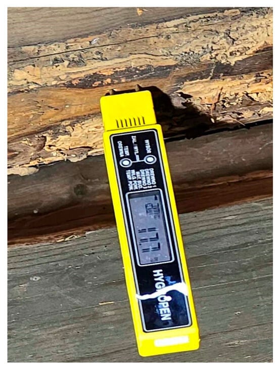
Figure 16.
Traces of damage caused by wood-destroying insects on a horizontal beam; moisture measurement.
Elements of the clasped purlin roof exhibited damage caused by wood-destroying insects (Figure 17, Figure 18, Figure 19 and Figure 20), Wood flour mixed with insect droppings was visible in the elements. The bright color of the material indicated that feeding activity was still ongoing. The exit holes were oval, 2–4 mm in diameter, and round, 1–1.5 mm in diameter. The greatest damage was observed on the horizontal beams located on the rafters, primarily on the southern side. Similar exit holes were also observed on a large portion of the board-and-batten siding of the exterior wall (Figure 21 and Figure 22). Large amounts of wood flour had accumulated beneath the battens, suggesting the presence of wood-destroying insects in the log frame or other elements covered with board-and-batten siding.
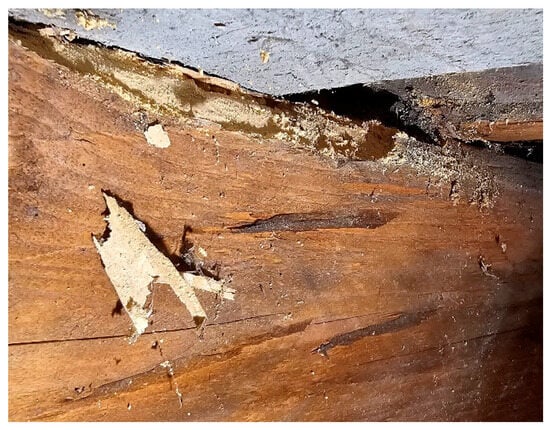
Figure 17.
Damage to the upper surface of the clasped purlin roof caused by wood-destroying insects.
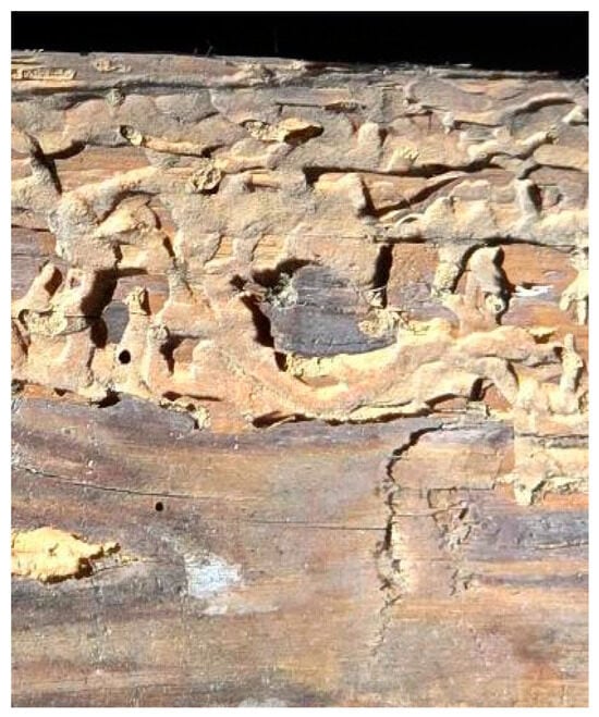
Figure 18.
Traces of damage caused by wood-destroying insects on a horizontal beam.
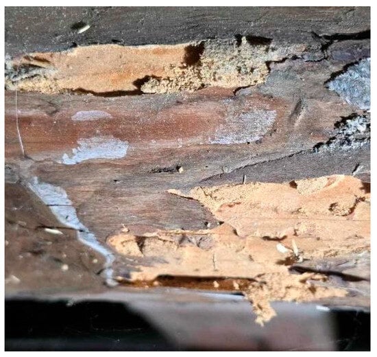
Figure 19.
Traces of damage caused by wood-destroying insects on the lower surface of the beam.
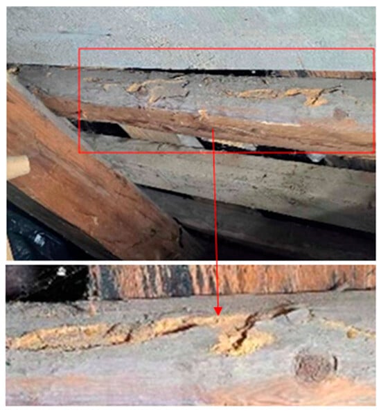
Figure 20.
Traces of damage caused by wood-destroying insects on a horizontal beam.
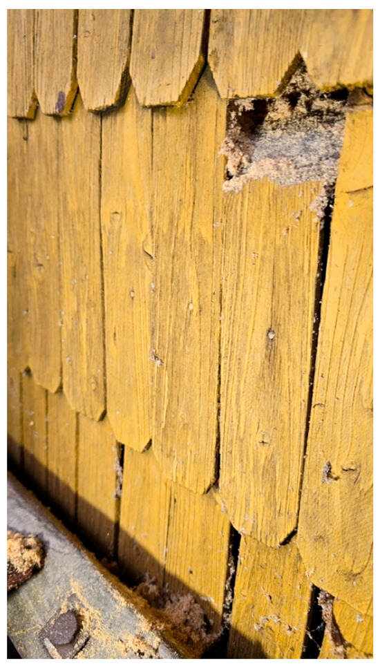
Figure 21.
Wood flour spilling from underneath the damaged batten.
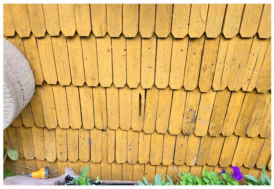
Figure 22.
Outlets visible on the board and batten siding of the northern exterior wall.
The characteristics of the damage, including the size and shape of the exit holes, suggest infestation by the deathwatch beetle (Xestobium rufovillosum) and the common furniture beetle (Anobium punctatum). No evidence was found of the house longhorn beetle (Hylotrupes bajulus), which is known to cause the most rapid and severe timber damage. Nevertheless, the identified species are considered among the most hazardous to traditional wooden architecture.
Moisture content measurements of the clasped purlin roof indicated timber dampness of 13–18%. In Polish climatic conditions, wood with a moisture content of 15–18% (depending on the season) is considered air-dry. Only moisture content above 20% creates conditions conducive to the growth of wood-destroying fungi.
The recommendations include the need for remedial measures. These must be tailored to the degree of damage and its location. No mycelium or fungi were found.
Significant batten damage was found in the lower corners of the eastern exterior walls, caused by biocorrosion. Under the missing board and batten siding, corroded log frame beams were clearly visible. The wood was dark and soft, at the brown corrosion stage (Figure 23), The measured timber moisture content was 22%. Additionally, beam damage by wood-destroying insects was visible.

Figure 23.
Damaged board and batten siding and corroded lower log frame beam.
The timber in the lower zone of the northern exterior walls was covered by growth (Figure 24). Small traces of biocorrosion in the form of wood discolouration and structure changes were found on window joinery elements and the wooden window trims (Figure 25).
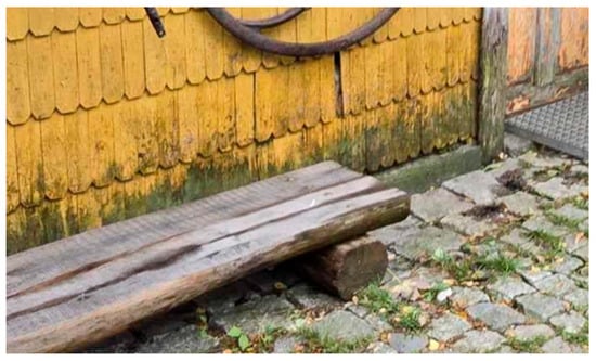
Figure 24.
Growth on the bottom of the northern exterior wall.
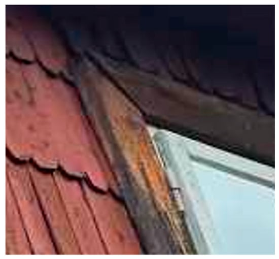
Figure 25.
Biocorrosion on the wooden trim of the attic window.
2.3. Adopted Upgrade Solutions
The main premise of the studies performed on the building was to identify a possible solution for improving its energy efficiency, in particular to limit the loss of heat through the building envelope.
Due to restrictions arising from the building’s historic status, thermal upgrades on the inside of the envelope components and thermal insulation of the ceiling above the ground floor were proposed.
For this purpose, two potential insulation solutions were analyzed:
- 10 cm—thick wood wool with λ = 0.036 [W/(m·K)]
- 6 cm—thick phenolic foam with λ = 0.021 [W/(m·K)].
The timber in the lower zone of the northern exterior walls was covered by growth (Figure 24).
Small traces of biocorrosion in the form of wood discoloration and structural changes were found on window joinery elements and the wooden window trim (Figure 25).
A variety of material solutions can be employed in internal insulation systems. However, their effectiveness must be carefully evaluated to determine the risk of moisture accumulation within the individual layers of the insulated assembly. To this end, comprehensive numerical analyses of moisture content changes over time were conducted, and both the qualitative and quantitative trends of these changes were assessed. Based on the results of this evaluation, an informed decision can be made regarding the suitability of a given insulation solution.
Thermal resistance was determined analytically based on the EN ISO 6946 standard [55]. The material data used for calculations are given in Table 2.
Table 2.
Technical parameters of materials [WUFI database].
The insulation thickness for each solution was adjusted so that both would have similar thermal resistance R ~ 2.8 [(m2·K)/W]—Table 3.
Table 3.
Summary of thermal conductivity for the analyzed envelope components.
The insulation thickness was selected so as to minimize the loss of heat and reduce the risk of mold growth on the surface of the envelope components. The planned envelope component does not need to meet the mandatory requirements specified in the relevant Polish regulations [56,57] (U ≤ 0.20 [W/(m2·K)]). Increasing the insulation thickness reduces the drying capacity of the envelope component and might damage the existing component.
The evaluation included 3 basic details for the current state, marked, respectively, as follows:
- D1_V0, D2_V0, D3_V0,
And 6 details for the upgraded state, marked, respectively, as follows:
- D1_V1; D2_V2; D2_V1; D2_V2; D3_V1; D3_V2.
Explanation of the markings:
- D1—Detail of the joint of two outer walls in room 1.3, the so-called exterior corner.
- D2—Detail of the joint of the outer wall with an inner wall in rooms 1.4 and 1.5.
- D3—Ceiling support on the outer wall, the so-called cold end.
- V0—Current state.
- V1—Thermal insulation with wood wool.
- V2—Thermal insulation with phenolic foam.
The analyzed junction models with the description of layers and thickness values are provided on the schematics in Figure 26, Figure 27 and Figure 28.
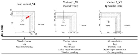
Figure 26.
Analyzed D1 detail with layer description.
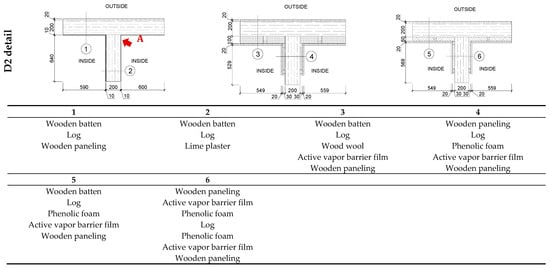
Figure 27.
Analyzed D2 detail with layer description.
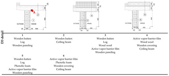
Figure 28.
Analyzed D3 detail with layer description.
For the details in question, an in-depth hygrothermal analysis was performed to assess the efficiency of the proposed solutions in the following context:
- Reducing loss of heat through the envelope components and eliminating the risk of mold growth on the component surfaces,
- Changing moisture content of materials over time in the existing and upgraded envelope components and drying up of timber elements.
3. Results and Discussion
3.1. Stationary Calculations
Stationary numerical analyses were performed using THERM software. The software was used to determine the temperature field distribution in the cross-section of selected building junctions and joints as shown in Figure 26, Figure 27 and Figure 28. Also, surface temperatures were gauged at sites with particularly high risk of mold growth—Figure 26, Figure 27 and Figure 28 site A. The gauged temperatures were then used to determine the fRsi factor estimating the mold growth risk.
The following parameters were used in the calculations:
- Constant exterior temperature Te = (−20 °C)
- Constant interior temperature Ti = 20 °C
- Heat transfer coefficient on the exterior surface: he = 25 [(m2·K)/W]
- Heat transfer coefficient on the interior surface: hi = 4.0 [(m2·K)/W]
- The technical parameters of materials are listed in Table 3 [based on the WUFI program database]
The purpose of the calculations was to assess the efficiency of the applied thermal upgrade solutions in the context of eliminating the risk of mold growth on the surface of the joints.
Figure 29, Figure 30, Figure 31, Figure 32, Figure 33 and Figure 34 show the colored distribution of isotherms and density of the heat flux for the analyzed details (the results are shown graphically only for the basic model V0 and variant V1. All results are summarized in Table 4).
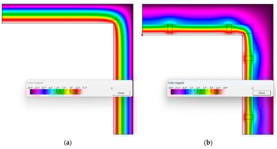
Figure 29.
Isotherm distribution for the detail: (a): D1_V0, (b): D1_V1.
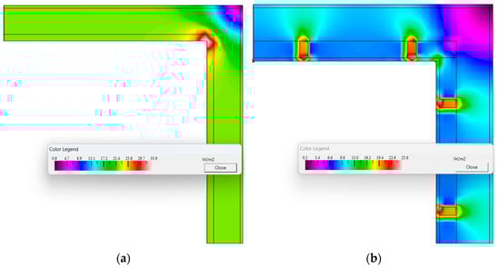
Figure 30.
Distribution of heat flux density for the detail: (a): D1_V0, (b): D1_V1.
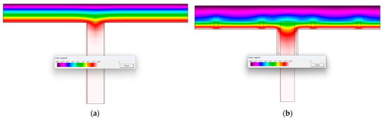
Figure 31.
Isotherm distribution for the detail: (a): D2_V0, (b): D2_V1.
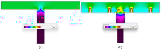
Figure 32.
Distribution of heat flux density for the detail: (a): D2_V0, (b): D2_V1.
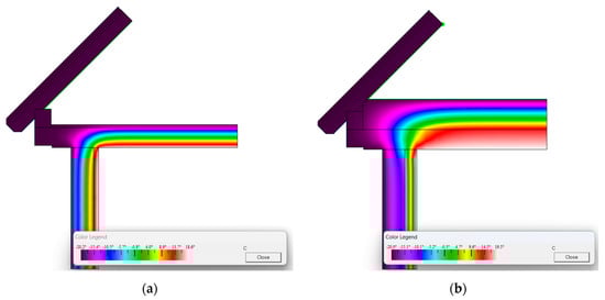
Figure 33.
Isotherm distribution for the detail: (a): D3_V0, (b): D3_V1.
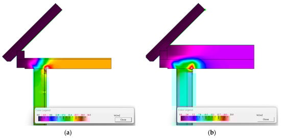
Figure 34.
Distribution of heat flux density for the detail: (a): D3_V0, (b): D3_V1.
Table 4.
Calculations of the fRsi temperature factor.
For the analyzed details, surface temperature was gauged on site A. The temperature was then used to determine the design value of the fRsi factor. It was referred to the fRsimax threshold value calculated for the conditions of the environment of the envelope component, as per ISO 13788 [58] standard—Table 4.
On the basis of the obtained results it was concluded for details D1_V0 and D3_V0 that there was risk of mold growth on the surface of the envelope component, i.e., fRsi < fRsimax, assuming variable internal conditions. Thermal insulation of the envelope components eliminates the mold growth risk in each case (details D1_V1/2–D3_V1/2).
3.2. Non-Stationary Calculations
Non-stationary numerical analyses were performed using WUFI 2D software. The software was used to determine the changes in the moisture content over time for the analyzed system of envelope components and their junctions. The calculations were based on a system of non-linear partial differential equations describing the unknown heat and moisture transfer in materials:
For one-dimensional heat flux, the transport equations take the following form [59]:
- heat transfer:
- moisture transfer:
| Dw | capillary transfer coefficient [m2/s] |
| H | enthalpy of moist material [J/m3] |
| hv | heat of evaporation [J/kg] |
| p | partial pressure of water vapor [Pa], |
| u | moisture content [m3/m3], |
| δo | diffusion coefficient of water vapor in air [kg/(m·s·Pa)], |
| T | temperature [°C], |
| λ | thermal conductivity coefficient of moist material [W/(m·K)] |
| µ | diffusion resistance coefficient of dry material [–], |
| ρw | water density [kg/m3], |
| φ | relative humidity [–]. |
The presented heat and moisture transfer model includes the sorption properties of materials and their ability to redistribute moisture, as well as all elements of exterior climate, including, among others, driving rain. Table 5 summarizes the basic hygrothermal functions for insulated partition materials.
Table 5.
Hygrothermal functions for selected materials [developed based on the WUFI database].
The input data and physical parameters of component materials are listed in Table 3.
The calculations were performed with the following assumptions:
- Internal climate according to EN 15026 standard [60]; average moisture load, Figure 35.
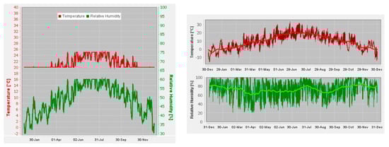 Figure 35. Assumed indoor and outdoor climate conditions (Bielsko-Biała) [based on WUFI].
 - Exterior climate for the city of Bielsko-Biała, (temperature, relative humidity, global radiation, diffuse solar radiation, direct solar radiation, and others), Figure 36 shows selected weather parameters.
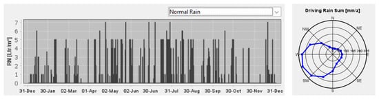 Figure 36. Driving rain [based on WUFI].
 - Rain load according to ASHRAE 160: rain exposure category: average, building height < 10 m,
- Thermal resistance Rsi = 0.13 [(m2·K)/W], Rse = 0.04 [(m2·K)/W],
- As the initial condition for all simulations, the exterior climate of 1 January 2025, 0:00 was used; all simulations were performed for a period of 3 years from the starting date, i.e., until 1 January 2028, 0:00.
- The initial water content in the material as of October 1st corresponds to the moisture content in the material at equilibrium with air at 80% humidity. Quantitative values for each material are given in Table 2.
The results of the calculations of the estimated changes in moisture content over time were shown for areas relevant in terms of construction and operation of the building. For each wall system (Figure 37) a simplified model was prepared with approximate sites of moisture content evaluation sites in the assumed observation period, i.e., over 3 years.
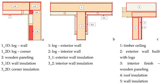
Figure 37.
Models of details with marked analysis areas: (a) D1 detail, (b) D2 detail, (c) D3 detail.
The results of the calculations of moisture content changes for specific materials are shown in Figure 38 and Table 6.
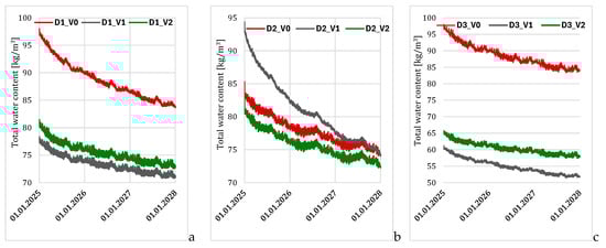
Figure 38.
Total water content changes in models: (a)—corner/D1, (b)—wall joint/D2, (c)—wall support of the ceiling/D3.
Table 6.
Total water content changes for the analyzed envelope component models.
Based on the analysis of the obtained data on changes in the total water content within the material layers of the analyzed details over time (Figure 39, Figure 40 and Figure 41), the following conclusions were drawn:
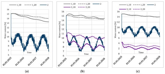
Figure 39.
Water content changes for D1 detail: (a): current state V0, (b): upgraded state V1, (c): upgraded state V2, markings as in Figure 19.
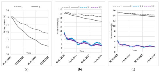
Figure 40.
Water content changes for D2 detail: (a): current state V0, (b): upgraded state V1, (c): upgraded state V2, markings as in Figure 19.
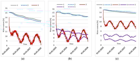
Figure 41.
Water content changes for D3 detail: (a): current state V0, (b): upgraded state V1, (c): upgraded state V2, markings as in Figure 37.
On the basis of the analysis of the obtained data on the changes in the total water content over time (Figure 38), it is concluded as follows:
- For the D1 model, adding thermal insulation of walls—regardless of the insulation material type—significantly reduced the moisture content in the entire system. The total moisture content in the upgraded systems was lower by at least 10 [kg/m3] than the current state at the and of the analyzed period.
- For the D2 model, differences in total moisture content for individual variants (V0, V1, V2) were observed at the beginning of the calculation period. The highest initial moisture content was found in variant V1, upgraded with wood wool, for which the initial moisture content was higher by around 10–12 [kg/m3] than V0 and V2 variants. At the end of the 3-year calculation period the envelope components dried up to virtually the same levels as in other variants;
For the D3 model, significant differences in the quantitative changes in moisture content were observed between individual variants, i.e., the highest moisture content was found in the current state (V0), both at the beginning of the calculation period and further on. For all variants of this model (V0, V1, V2), a similar qualitative trend of the entire junction drying was visible.
Detail D1—In the reference state (V0), a drying tendency was observed in the main timber structural elements. The wall timber beam dried to approximately 13%M in the flat wall cross-section and to 14%M in the corner cross-section. At no point did the moisture content exceed the threshold value that could initiate biocorrosion. In the thermal upgrade variants (V1 and V2), a continuing downward trend in the moisture content of the wall timber elements was identified, reaching around 14%M at the end of the calculation period. The insulation materials exhibited sinusoidal variations in moisture content over time. For both thermal upgrade variants, differences in the moisture content of the insulation materials were observed: in the flat wall (D1) and corner (D2), the values reached up to 2.5%M for variant V1 and 1%M for variant V2.
Detail D2—In the reference state (V0), a pronounced drying trend of the structural elements was recorded. For the exterior log wall, the moisture content decreased by approximately 2%M relative to the baseline, whereas for the interior log wall, the reduction was greater, reaching around 4%M. The application of thermal insulation (V1, V2) significantly reduced the drying intensity of the timber structural elements: the decrease in moisture content was approximately 0.6%M for the exterior wall and 2%M for the interior wall, relative to the baseline. Nevertheless, in all analyzed cases, a general reduction in timber moisture content was observed. In the thermally upgraded variants (V1 and V2), sinusoidal variations in moisture content with an overall downward trend were noted.
Detail D3—In the reference state, a downward trend in moisture content was observed for both the log wall and the timber ceiling located above the unheated attic. At the end of the calculation period, the moisture content was lower than at baseline. The application of thermal insulation in variants V1 and V2 reduced the rate of drying of the timber elements; however, a continuous downward trend in moisture content over time remained visible. For the thermally upgraded variants (V1 and V2), both qualitative and quantitative differences in the moisture content evolution were observed for all insulation types, yet in all cases the overall trend remained downward.
General conclusion—Both insulation solutions (V1 and V2) do not contribute to an increase in the moisture level within the insulated wall system layers and can therefore be safely applied in the analyzed case. The selection of the appropriate insulation material should additionally be supported by a comprehensive economic and environmental assessment, taking into account the ecological footprint of the product.
4. Conclusions
Regional architectural monuments constitute a crucial component of cultural heritage. Contemporary climate policies impose significant challenges on civil engineers, architects, and interdisciplinary construction teams. Decisions concerning the enhancement of the energy performance of historic buildings must therefore be made with particular care and based on a thoroughly developed and well-substantiated plan of action. Only under such conditions can a sustainable balance be achieved between the preservation of regional cultural and architectural heritage values and compliance with the requirements arising from current climate policy frameworks.
Based on the findings of the conducted research, the following conclusions can be drawn:
- Historic buildings exhibit unique regional structural and architectural characteristics.
- Although unconventional construction solutions represent an important element of regional cultural heritage, they may have an adverse impact on the building’s thermal performance (e.g., in the Silesian Beskids, the “cold end” exhibited a temperature up to 6 °C lower than the remainder of the external envelope) and thus require particular attention from designers.
- The application of internal insulation necessitates a detailed evaluation of the potential increase in moisture content within the insulated system components, as well as the associated risk of mold growth.
In the analyzed case, for a thermal transmittance value of U = 0.24 [W/(m2K)], the Temperature factor fRsi in each tested location exceeded the threshold value of 0.780 (as determined in accordance with ISO 13788), indicating no predicted risk of mold growth on the internal surfaces of the building envelope.
- The proposed thermal modernization measures, involving internal insulation of the building envelope, did not result in an increase in the moisture content of the insulation system components during the monitoring period.
- The technical condition of historic buildings constitutes one of the key determinants in defining the future course of remedial actions.
Drawing on the presented case study and the authors’ professional experience, a detailed procedure for improving the thermal performance of historic buildings has been developed, based on the principles outlined in EN 16883. The procedure incorporates aspects specific to regional wooden historic structures (see Figure 42). This document presents the principal outcomes of the authors’ research, aimed at achieving a balance between safeguarding cultural values and meeting contemporary climate policy requirements, in line with the vision of the New European Bauhaus.
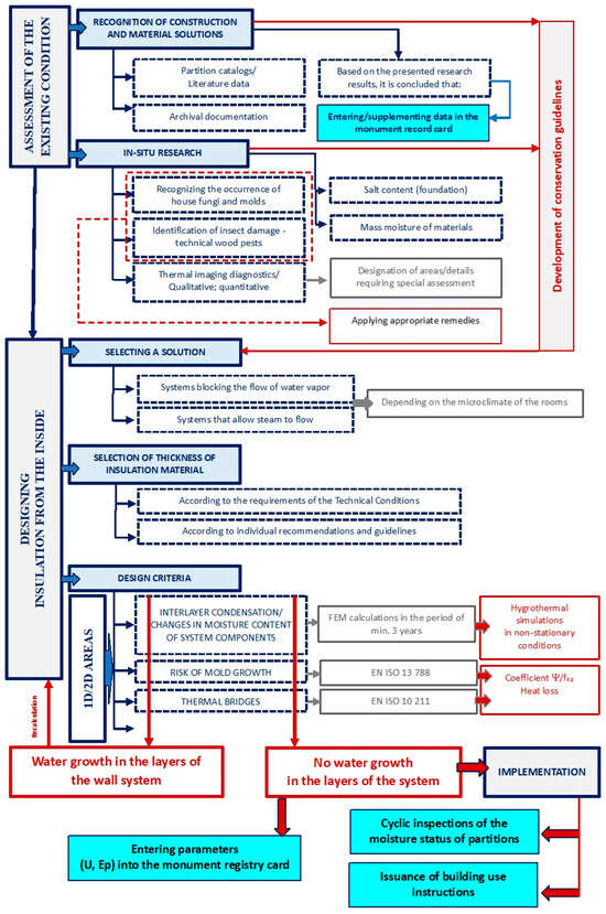
Figure 42.
Proposed procedure for designing thermal modernization solutions for wooden buildings.
The added value of this research is represented by the following recommendations:
- Supplementing (or establishing, where absent) the Heritage Register Card in order to document distinctive regional architectural and structural characteristics of buildings. The obligatory nature of this activity should be formally established in legal regulations.
- Supplementing (or establishing, where absent) the Heritage Register Card with new energy performance parameters (e.g., U and EP values) resulting from both design assumptions and as-built performance. Such actions should likewise be mandated by relevant legal provisions.
- Performing periodic five-year assessments of the moisture condition of building envelopes, which could complement standard technical inspections as stipulated by Polish building law.
- Preparing and issuing user manuals by the designer, containing detailed recommendations for ongoing operation and maintenance (e.g., regarding indoor humidity control, permissible modifications to the building envelope, etc.) that may affect both the thermal-moisture performance of the building and its cultural heritage values.
Author Contributions
B.O.-K.: Conceptualization, Formal analysis, Methodology, Investigation, Software, Supervision, Project administration, Writing—original draft. A.S.-G.: Conceptualization, Methodology, Investigation, Resources, Writing—original draft. E.R.-A.: Conceptualization, Formal analysis, Investigation, Visualization. All authors have read and agreed to the published version of the manuscript.
Funding
This research received no external funding.
Data Availability Statement
The original contributions presented in this study are included in the article. Further inquiries can be directed to the corresponding author.
Acknowledgments
This study was conducted on the basis of the PBL (Project Base Learning) project: Improving the energy efficiency of historic buildings while preserving the cultural heritage values. The project was headed by Bożena Orlik−Kożdoń, Agnieszka Szymanowska−Gwiżdż, and Elżbieta Rdzawska−Augustin, The following students participated in the project: Monika Czyżykowska, Weronika Kopyciok, Tomasz Skrzypiec, Zofia Bekman, Igor Gdula.
Conflicts of Interest
The authors declare no conflicts of interest.
References and Note
- Adams, C.; Douglas-Jones, R.; Green, A.; Lewis, Q.; Yarrow, T. Building with history: Exploring the relationship between heritage and energy in institutionally managed buildings. Hist. Environ. Policy Pract. 2014, 5, 167–181. [Google Scholar] [CrossRef]
- Camuffo, D.; Van Grieken, R.; Busse, H.J.; Sturaro, G.; Valentino, A.; Bernardi, A.; Blades, N.; Shooter, D.; Gysels, K.; Deutsch, F.; et al. Environmental monitoring in four European museums. Atmos. Environ. 2001, 35, 127–140. [Google Scholar] [CrossRef]
- Chitty, G.; Smith, C. Principles into Policy: Assessing the Impact of Conservation Principles in Local Planning Policy. Hist. Environ. Policy Pract. 2019, 10, 282–299. [Google Scholar] [CrossRef]
- Fabbri, K.; Zuppiroli, M.; Ambrogio, K. Heritage buildings and energy performance: Mapping with GIS tools. Energy Build. 2012, 48, 137–145. [Google Scholar] [CrossRef]
- Stazi, F.; Vegliò, A.; Di Perna, C.; Munafò, P. Experimental comparison between 3 different traditional wall constructions and dynamic simulations to identify optimal thermal insulation strategies. Energy Build. 2013, 60, 429–441. [Google Scholar] [CrossRef]
- European Commission. Communication from the Commission to the European Parliament, the European Council, the Council, the European Economic and Social Committee and the Committee of the Regions: A Renovation Wave for Europe—Greening Our Buildings, Creating Jobs, Improving Lives; European Commission: Brussels, Belgium, 2020. [Google Scholar]
- New European Bauhaus: A Handbook. 2023. Available online: https://built4people.eu/wp-content/uploads/2023/10/New-European-Bauhaus-a-handbook.pdf (accessed on 12 December 2024).
- Directive (EU) 2024/1275 of the European Parliament and of the Council of 24 April 2024 on the Energy Performance of Buildings (recast) (Text with EEA Relevance). Available online: https://eur-lex.europa.eu/eli/dir/2024/1275/oj/eng (accessed on 13 October 2025).
- Ascione, F.; Cheche, N.; De Masi, R.F.; Minichiello, F.; Vanoli, G.P. Design the refurbishment of historic buildings with the cost-optimal methodology: The case study of a XV century Italian building. Energy Build. 2015, 99, 162–176. [Google Scholar] [CrossRef]
- Ascione, F.; De Rossi, F.; Vanoli, G.P. Energy retrofit of historical buildings: Theoretical and experimental investigations for the modelling of reliable performance scenarios. Energy Build. 2011, 43, 1925–1936. [Google Scholar] [CrossRef]
- European Commission. Communication from the Commission to the European Parliament, the Council, the European Economic and Social Committee and the Committee of the Region–COM(2011) 571 Final–Roadmap to a Resource Efficient Europe, Brussels; European Commission: Brussels, Belgium, 2011. [Google Scholar]
- IEA. Key World Energy Statistics—2012; IEA: Paris, France, 2012. [Google Scholar]
- World Development Indicators 2012. Available online: https://documents1.worldbank.org/curated/en/553131468163740875/pdf/681720PUB0EPI004019020120Box367902B.pdf (accessed on 12 December 2024).
- Verbeeck, G.; Hens, H. Energy savings in retrofitted dwellings: Economically viable? Energy Build. 2005, 37, 747–754. [Google Scholar] [CrossRef]
- Verbruggen, A. Retrofit of a century old land-house to a low-energy house. Int. J. Environ. Technol. Manag. 2008, 9, 402. [Google Scholar] [CrossRef]
- Wang, C.; Cho, Y.K. Performance Evaluation of Automatically Generated BIM from Laser Scanner Data for Sustainability Analyses. Procedia Eng. 2015, 118, 918–925. [Google Scholar] [CrossRef]
- Buildings Performance Institute Europe (BPIE). Europe’s Buildings Under the Microscope; BPIE: Brussels, Belgium, 2011. [Google Scholar]
- Mazzarella, L. Energy retrofit of historic and existing buildings. The legislative and regulatory point of view. Energy Build. 2015, 95, 23–31. [Google Scholar] [CrossRef]
- Boarin, P.; Guglielmino, D.; Pisello, A.L.; Cotana, F. Sustainability assessment of historic buildings: Lesson learnt from an Italian case study through LEED® rating system. Energy Procedia 2014, 61, 1029–1032. [Google Scholar] [CrossRef]
- De Santoli, L. Guidelines on energy efficiency of cultural heritage. Energy Build. 2015, 86, 534–540. [Google Scholar] [CrossRef]
- EN 16883:2017; Conservation of Cultural Heritage—Guidelines for Improving the Energy Performance of Historic Buildings. British Standards Institution: London, UK, 2017.
- Buda, A.; Gori, V.; Hansen EJde, P.; López, C.S.P.; Marincioni, V.; Giancola, E.; Vernimme, N.; Egusquiza, A.; Haas, F.; Herrera-Avellanosa, D. Existing tools enabling the implementation of EN 16883:2017 Standard to integrate conservation-compatible retrofit solutions in historic buildings. J. Cult. Heritage 2022, 57, 34–52. [Google Scholar] [CrossRef]
- Leijonhufvud, G.; Broström, T.; Buda, A. An Evaluation of the Usability of EN 16883:2017. Suggestions for Enhancing the European Guidelines for Improving the Energy Performance of Historic Buildings, 76; International Energy Agency: Paris, France, 2021. [Google Scholar] [CrossRef]
- AiCARR. Energy Efficiency in Historic Buildings; AiCARR Publication: Milan, Italy, 2014. [Google Scholar]
- Bjelland, D.; Collins, D.; Gullbrekken, L.; Hrynyszyn, B.D. Energy retrofitting of heritage-protected buildings: Establishing representative case studies. Energy Rep. 2025, 13, 2752–2763. [Google Scholar] [CrossRef]
- Blumberga, A.; Freimanis, R.; Biseniece, E.; Kamenders, A. Hygrothermal Performance Evaluation of Internally Insulated Historic Stone Building in a Cold Climate. Energies 2023, 16, 866. [Google Scholar] [CrossRef]
- Cho, H.M.; Yun, B.Y.; Kim, Y.U.; Yuk, H.; Kim, S. Integrated retrofit solutions for improving the energy performance of historic buildings through energy technology suitability analyses: Retrofit plan of wooden truss and masonry composite structure in Korea in the 1920s. Energy Rev. 2022, 168, 112800. [Google Scholar] [CrossRef]
- Di Ruocco, G.; Sicignano, C.; Sessa, A. Integrated Methodologies Energy Efficiency of Historic Buildings. Procedia Eng. 2017, 180, 1653–1663. [Google Scholar] [CrossRef]
- Leijonhufvud, G.; Eriksson, P.; Broström, T. Energy efficiency in historic buildings. In Routledge Handbook of Sustainable Heritage; Routledge: Oxfordshire, UK, 2022. [Google Scholar] [CrossRef]
- Lucchi, E. Energy Efficiency of Historic Buildings. Buildings 2022, 12, 200. [Google Scholar] [CrossRef]
- Martín-Garín, A.; Millán-García, J.A.; Terés-Zubiaga, J.; Oregi, X.; Rodríguez-Vidal, I.; Baïri, A. Improving Energy Performance of Historic Buildings through Hygrothermal Assessment of the Envelope. Buildings 2021, 11, 410. [Google Scholar] [CrossRef]
- Nair, G.; Verde, L.; Olofsson, T. A Review on Technical Challenges and Possibilities on Energy Efficient Retrofit Measures in Heritage Buildings. Energies 2022, 15, 7472. [Google Scholar] [CrossRef]
- Hansen, T.K.; Bjarløv, S.P.; Peuhkuri, R.H.; Harrestrup, M. Long term in situ measurements of hygrothermal conditions at critical points in four cases of internally insulated historic solid masonry walls. Energy Build. 2018, 172, 235–248. [Google Scholar] [CrossRef]
- Hansen, T.K. Hygrothermal Performance of Internal Insulation in Historic Buildings. Ph.D. Thesis, Department of Civil Engineering, Technical University of Denmark, Kongens Lyngby, Denmark, 2019. Available online: https://vbn.aau.dk/files/549548055/Byg_R399_Hygrothermal_performance_of_internal_insulation_in_historic_buildings.pdf (accessed on 8 July 2024).
- Zagorskas, J.; Zavadskas, E.K.; Turskis, Z.; Burinskiene, M.; Blumberga, A.; Blumberga, D. Thermal insulation alternatives of historic brick buildings in Baltic Sea Region. Energy Build. 2014, 78, 35–42. [Google Scholar] [CrossRef]
- Orlik-Kożdoń, B. Interior insulation of masonry walls-selected problems in the design. Energies 2019, 12, 3895. [Google Scholar] [CrossRef]
- Orlik-Kożdoń, B.; Steidl, T. Impact of internal insulation on the hygrothermal performance of brick wall. J. Build. Phys. 2016, 41, 120–134. [Google Scholar] [CrossRef]
- Orlik-Kożdoń, B.; Radziszewska-Zielina, E.; Fedorczak-Cisak, M.; Steidl, T.; Białkiewicz, A.; Żychowska, M.; Muzychak, A. Historic building thermal diagnostics algorithm presented for the example of a townhouse in Lviv. Energies 2020, 13, 5374. [Google Scholar] [CrossRef]
- Ma, Z.; Cooper, P.; Daly, D.; Ledo, L. Existing building retrofits: Methodology and state-of-the-art. Energy Build. 2012, 55, 889–902. [Google Scholar] [CrossRef]
- Fedorczak-Cisak, M.; Radziszewska-Zielina, E.; Orlik-Kozdoń, B.; Steidl, T.; Tatara, T. Analysis of the thermal retrofitting potential of the external walls of podhale’s historical timber buildings in the aspect of the non-deterioration of their technical condition. Energies 2020, 13, 4610. [Google Scholar] [CrossRef]
- Chang, S.J.; Kang, Y.; Yun, B.Y.; Yang, S.; Kim, S. Assessment of effect of climate change on hygrothermal performance of cross-laminated timber building envelope with modular construction. Case Stud. Therm. Eng. 2021, 28, 101703. [Google Scholar] [CrossRef]
- Staněk, K.; Tywoniak, J.; Richter, J.; Bureš, M.; Kopecký, P.; Volf, M. Studies on hygrothermal performance of wood elements in building constructions-remarks on methodology. Wood Res. 2016, 61, 637–650. [Google Scholar]
- Akbarinejad, T.; Machlein, E.; Bertolin, C.; Ogut, O.; Lobaccaro, G.; Salaj, A.T. Harvesting Solar Energy for Sustainable and Resilient historical areas. A Norwegian Case study. Procedia Struct. Integr. 2024, 55, 46–56. [Google Scholar] [CrossRef]
- López, C.S.; Frontini, F. Energy efficiency and renewable solar energy integration in heritage historic buildings. Energy Procedia 2014, 48, 1493–1502. [Google Scholar] [CrossRef]
- López, C.S.P.; Lucchi, E.; Leonardi, E.; Durante, A.; Schmidt, A.; Curtis, R. Risk-benefit assessment scheme for renewable solar solutions in traditional and historic buildings. Sustainability 2021, 13, 5246. [Google Scholar] [CrossRef]
- López, I.D.; Olivieri, L. Comprehensive review of building-integrated photovoltaics in the renovation of heritage buildings. J. Build. Eng. 2025, 108, 112883. [Google Scholar] [CrossRef]
- Franco, G.; Magrini, A.; Cartesegna, M.; Guerrini, M. Towards a systematic approach for energy refurbishment of historical buildings. the case study of Albergo dei Poveri in Genoa, Italy. Energy Build. 2015, 95, 153–159. [Google Scholar] [CrossRef]
- Asadi, E.; da Silva, M.G.; Antunes, C.H.; Dias, L.; Glicksman, L. Multi-objective optimization for building retrofit: A model using genetic algorithm and artificial neural network and an application. Energy Build. 2014, 81, 444–456. [Google Scholar] [CrossRef]
- Penna, P.; Prada, A.; Cappelletti, F.; Gasparella, A. Multi-objectives optimization of Energy Efficiency Measures in existing buildings. Energy Build. 2015, 95, 57–69. [Google Scholar] [CrossRef]
- Agnieszka, M. Drewniana Chałupa Wiślańskiego Górala na Wybranych Przykładach; Gont: Katowice, Poland, 2017; pp. 87–106. [Google Scholar]
- Antonina, Ż. Dranica, Gont i Szkudła w Literaturze Polskiej w Okresie od XVI do 1 Połowy XX Wieku; Gont: Katowice, Poland, 2017; pp. 17–31. [Google Scholar]
- Kawulok, M. Charakterystyka Budownictwa Drewnianego w Wiśle w Świetle Zasobów Archiwum Państwowego w Cieszynie; Gont: Katowice, Poland, 2017; pp. 65–85. [Google Scholar]
- Polish regulations: RESOLUTION NO. XXXVIII/598/2014 OF THE WISŁA CITY COUNCIL of 29 May 2014.
- ISO 9869:2014; Thermal Insulation—Building Elements—In-Situ Measurement of Thermal Resistance and Thermal Transmittance Part 1: Heat Flow Meter Method. ISO: Geneva, Switzerland, 2014.
- ISO 6946:2017; Building Components and Building Elements—Thermal Resistance and Thermal Transmittance—Calculation Methods. ISO: Geneva, Switzerland, 2017.
- Polish regulations: Act of 23 July 2003 on the protection and care of monuments. J. Laws 2003, 162, 1568.
- Polish regulations: Regulation of the Minister of Infrastructure on the technical requirements that buildings and their location should meet. Regulation of 12 April 2002. J. Laws 2019, 1065, Consolidated text–Including the amendments introduced. J. Laws 2020, 1608.
- ISO 13788:2013; Hygrothermal Performance of Building Components and Building Elements—Internal Surface Temperature to Avoid Critical Surface Humidity and Interstitial Condensation—Calculation Methods. ISO: Geneva, Switzerland, 2013.
- Kunzel, H. Simultaneous Heat and Moisture Transport in Building Components. One- and Two-Dimensional Calculation Using Simple Parameters. Available online: https://www.researchgate.net/publication/41124856_Simultaneous_heat_and_moisture_transport_in_building_components_One-_and_two-dimensional_calculation_using_simple_parameters (accessed on 13 October 2025).
- EN 15026:2008; Hygrothermal Performance of Building Components and Building Elements—Assessment of Moisture Transfer by Numerical Simulation. European Committee for Standardization: Brussels, Belgium, 2008.


Disclaimer/Publisher’s Note: The statements, opinions and data contained in all publications are solely those of the individual author(s) and contributor(s) and not of MDPI and/or the editor(s). MDPI and/or the editor(s) disclaim responsibility for any injury to people or property resulting from any ideas, methods, instructions or products referred to in the content. |
© 2025 by the authors. Licensee MDPI, Basel, Switzerland. This article is an open access article distributed under the terms and conditions of the Creative Commons Attribution (CC BY) license (https://creativecommons.org/licenses/by/4.0/).