Article

Maximum Torque per Ampere Control of IPMSM Based on Current Angle Searching with Sliding-Mode Extremum Seeking

1
School of Automation Sicence and Electrical Engineering, Beihang University, Beijing 100000, China
2
Jiangsu Guochuan Electric Co., Ltd., Xuzhou 221008, China
3
School of Electrical Engineering, China University of Mining and Technology, Xuzhou 221008, China
*
Author to whom correspondence should be addressed.
Energies 2025, 18(21), 5613; https://doi.org/10.3390/en18215613 (registering DOI)
Submission received: 9 September 2025 / Revised: 21 October 2025 / Accepted: 23 October 2025 / Published: 25 October 2025

Abstract

Model-based maximum torque per ampere (MTPA) control methods of interior permanent magnet synchronous motors (IPMSM) often suffer from poor robustness. To address this issue, a new MTPA control method based on current angle searching with sliding-mode extremum seeking is proposed. Based on Lyapunov’s criterion, the stability of the proposed MTPA method is proven. By analyzing the formation and switching process of a sliding-mode surface, the convergence speed and control accuracy of the proposed MTPA are derived. Compared with the conventional MTPA method, based on the sinusoidal excitation extremum search algorithm, the proposed method does not require either a sinusoidal excitation signal or high-pass and low-pass filters. The effectiveness of the proposed method is verified by experiment.

1. Introduction

The efficiency optimization control of an interior permanent magnet synchronous motor (IPMSM) is achieved by reducing losses. The losses of IPMSM mainly include copper loss and iron loss [1]. The copper loss model of IPMSM is simple to model. For the same output as an electromagnetic torque, achieving minimum copper loss control only requires optimizing the stator current amplitude: that is, the maximum torque per ampere (MTPA) control. MTPA control is currently the main means of efficiency optimization control below the base speed of IPMSM. MTPA control allocates d and q-axis currents reasonably to fully utilize the reluctance torque, and can be mainly divided into three categories: look-up table methods [2,3,4,5], a model-based method [6,7,8,9,10], and an online search algorithm [11,12,13,14,15,16].
The look-up table method achieves MTPA control by pre-creating a current distribution table, primarily based on experimental test data. To achieve high-precision MTPA control, the look-up table method requires extensive preliminary experiments [2]. To simplify the workload of preliminary experiments for MTPA control using the look-up table method, a MTPA curve-fitting algorithm, based on a nonlinear flux linkage model, is proposed in the literature [3]. This method only requires the collection of operating parameters at nine operating points, and uses mathematical fitting, based on the established nonlinear mathematical model to obtain the d-axis and q-axis current reference values under other operating conditions. In the literature [4], the MTPA curve is approximated as a straight line, and only the MTPA operating points on the maximum current limit circle are required to fit other MTPA operating points. The calculation accuracy depends on the degree of variation in motor parameters. For IPMSMs with a high-saturation design, the MTPA operating points obtained by this method deviate significantly from the actual situation. The issues associated with misaligned rotor positions or whistling problems that are pertinent to inappropriate power conversion strategies for the LUT methods are addressed in [5].
The model-based MTPA method utilizes the mathematical model of IPMSM to obtain the d-axis and q-axis current distribution scheme, requiring detailed parameters of inductance and rotor flux linkage. Traditional methods directly utilize the rated parameters of the motor to calculate the MTPA operating point, which is computationally complex and has poor robustness [6]. In response to deviations from the actual MTPA operating point, caused by model parameter errors, the literature [7] proposes an electromagnetic field finite element analysis method based on frozen permeability. This method primarily considers the variation in q-axis inductance with the current, effectively improving the accuracy of tracking the MTPA operating point. The online parameter estimations [8,9,10] are conducted to increase the accuracy of the MTPA control. However, since most of these methods do not fully consider the derivatives of machine parameters with respect to the current angle or d-axis current, these methods still cannot accurately calculate the MTPA operation point.
MTPA control based on online search methods primarily falls into two categories: numerical analysis methods and extremum seeking algorithms. In [11], the Newton method is adopted to obtain the optimal current for the MTPA point. An online MTPA angle search method is developed to achieve the minimization of the stator current for the specific output torque and speed [12]. Extremum seeking algorithms based on MTPA control methods include real and virtual signal injection control. The literature [13] tracks the MTPA operating point online by injecting high-frequency sinusoidal excitation into the current vector angle and demodulating the motor mechanical power change information through low-pass and band-pass filters. The literature [14] extracts the torque response by injecting a sinusoidal high-frequency signal on the d-axis current to adjust the lead angle online. The algorithms in the literature [13,14] essentially belong to the sinusoidal excitation extremum search algorithm, and the literature [13,14] theoretically analyze the convergence, convergence time, and robustness of the algorithm, and provide the design method of related parameters. MTPA control based on virtual signal injection [15,16] mathematically injects the desired signals into the current vector angle and then detects the MTPA operating points, according to the virtual system response. However, their demodulation process requires the use of low-pass filters (LPF) and band-pass filters (BPF), which heavily deteriorate the dynamic response of the system.
MTPA control based on online search methods does not require IPMSM parameters and exhibits strong robustness, making it a current research hotspot. However, most studies remain within the scope of sine excitation extremum search algorithms, and the signal demodulation process requires low-pass, band-pass, and other filtering steps, which not only increases system complexity but also has a certain impact on the steady-state and dynamic performance of the control system.
The above analysis indicates that, although the MTPA based on sine excitation extremum search algorithms can address the poor robustness of model-based methods, there are still some bottleneck issues that are difficult to resolve. Accordingly, this paper introduces the sliding-mode extremum seeking (SMES) algorithm into the control of MTPA to replace the traditional sine excitation extremum search algorithms. The relationship between the current amplitude and angle is firstly derived for the MTPA operation. Then, the current angle searching process with SMES is designed to realize the tracking of the MTPA point. The performance analysis of the SMES-based MTPA, including the stability, convergence speed, and control accuracy, are given. Compared to the sine excitation extremum search algorithm, the proposed method has the advantage of being structurally simple and eliminating the need for multiple filters. The simulation and experiment results are given to show the effectiveness of the proposed method.

2. MTPA Model and Control of IPMSM Based on Current Angle Searching with SMES

2.1. MTPA Model of IPMSM

The state equations of the current model of IPMSM in the synchronous rotating coordinate (d–q) is given, written as the following:
x t t = A x t + B u t + E ,
where
x = i d i q T ,   u = u d   u q T ,   E = 0     ω e ψ f L q , A = R L d ω e L q L d ω e L d L q R L q , B = 1 / L d 0 0 1 / L q ,
where R is the stator resistance; Pn is the pole pairs; ψf represents the permanent magnet flux linkage; ωe is the electric angular velocity; ud,q, id,q, and Ld,q represent the stator voltages, the stator currents, and the stator inductances in d-q axes, respectively. Te denotes the load and electromagnetic torque.
T e = 1.5 P n ψ f i q + L d L q i d i q ,
The operation analysis diagram of IPMSM is shown in Figure 1, where the horizontal and vertical axes represent the d-axis and q-axis currents, respectively. The O point is the origin of the coordinate, and pointing in the direction of the arrow indicates that the corresponding coordinate axis value is positive. Firstly, the amplitude of the stator current of IPMSM cannot exceed its maximum allowable value (Ilim as shown in Figure 1), which is reflected as the current limit circle in Figure 1. The actual operating state of IPMSM must be within the current limit circle. The constant torque curve shown in Figure 1 refers to the trajectory formed by the combination of d-axis and q-axis currents with the same electromagnetic torque. The constant torque curve shown in Figure 1 refers to the trajectory formed by the combination of the d-axis and q-axis currents with the same electromagnetic torque. In addition, the point on these constant torque curves that corresponds to the minimum current amplitude is the MTPA point. Taking Point A as an example, it represents the situation of the MTPA point, and the angle between the line connecting Point A and Point O and the d-axis is defined as the current vector angle (δ).
In polar coordinates, id and iq can be expressed as the following:
i d = | i s | c o s ( δ )
i q = | i s | s i n ( δ )
When the electromagnetic torque is positive, the range of δ is [π/2, π). When the electromagnetic torque is negative, its range is (−π, −π/2].
Substituting Equations (3) and (4) into the torque equation yields the electromagnetic torque equation in polar coordinates, as follows:
T e = 1.5 P n [ ψ f i s sin δ + ( L d L q ) i s 2 s i n ( 2 δ ) / 2 ] ,
Equation (5) indicates that the electromagnetic torque is an odd function, with respect to δ. To simplify the analysis process, the following discussion assumes the electromagnetic torque is greater than 0. For cases where the electromagnetic torque is less than 0, simply invert the sign of δ.
Assuming the electromagnetic torque is constant, the relationship between the current amplitude and angle can be derived as follows:
i s δ = P n 2 ψ f 2 s i n 2 δ + 4 3 P n T e ( L d L q ) s i n ( 2 δ ) P n ψ f s i n ( δ ) P n ( L d L q ) s i n ( 2 δ ) ,
Differentiating with respect to is yields the following:
d i s d δ = i s ψ f cos δ + i s L d L q cos 2 δ ψ f sin β + i s L d L q sin 2 δ ,
Setting Equation (7) equal to zero yields the following condition for the MTPA operating point:
cos δ mtpa = C mtpa C mtpa 2 + 8 i s 2 4 i s ,
In the equation, δmtpa represents the stator current vector angle corresponding to the MTPA operating point, and Cmtpa is defined as the MTPA constant, expressed as follows:
C mtpa = ψ f i d , q , T L q i d , q , T L d i d , q , T ,

2.2. MTPA Control of IPMSM Based on Current Angle Searching with SMES

Equation (8) demonstrates that the MTPA operation can be achieved by regulating the stator current vector angle δmtpa. It is indicated by (9) that the MTPA operation is dependent on the parameters of IPMSM, which are varied with the operation state due to the magnetic saturation and temperature change. In practical applications, these varied motor parameters may not be known exactly a priori, and thus, the extremum in the reference-to-output mapping may be ambiguous. In this part, a robust and accurate MTPA method is proposed through online searching δ with sliding-mode extreme seeking (SMES).
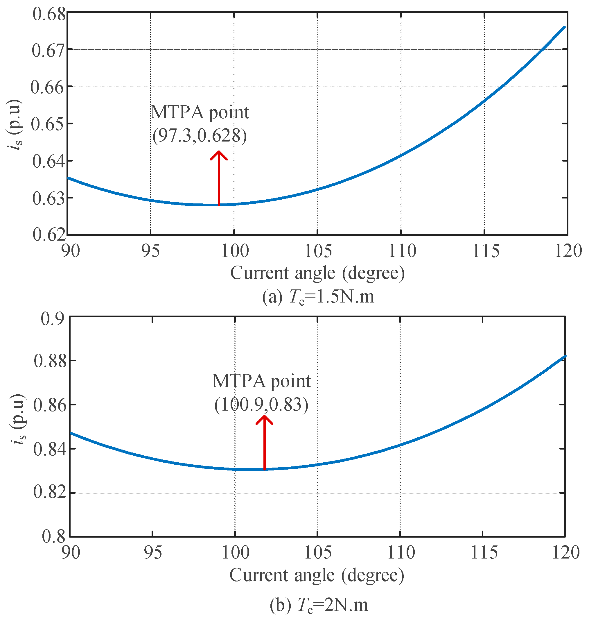
Using the permanent magnet synchronous motor (PMSM) parameters listed in Table 1, Figure 2a,b presents the constant–torque curves in polar coordinates under different electromagnetic torque conditions. The results demonstrate that distinct current vector angles correspond to different current magnitudes, with the operating point exhibiting the minimum current amplitude, representing the MTPA condition.
Figure 3 presents the derivative curve of is with respect to the current vector angle. As observed in Figure 3, the gradient of is versus δ is a monotonically increasing function of δ. For all points on the same side of the optimal operating point, the absolute value of the gradient increases with greater distance from the optimum. This analysis demonstrates that under constant electromagnetic torque conditions, the function is (δ) is a continuous concave function. Consequently, the sliding-mode extremum seeking (SMES) algorithm can be effectively employed to automatically locate the MTPA operating point.
The block diagram of the sliding-mode extremum seeking (SMES) MTPA control system, with the current vector angle as the search variable, is shown in Figure 4. Here, ρ, k, and α are constants satisfying ρ < 0, k > 0, and α > 0, respectively. The stator current reference value (is*) is obtained from the speed control loop. Since the electromagnetic torque of the IPMSM remains constant when the system is stable, the method in Figure 4 employs the SMES algorithm to search for the optimal current vector angle under constant torque conditions, thereby minimizing the stator current amplitude to achieve MTPA control.
In Figure 4, the stator current is first processed through an absolute value module to obtain its magnitude, which serves as the cost function for the sliding-mode extremum seeking algorithm. Furthermore, the switching function s(t) is expressed as follows:
s t = i s * ρ t
During the search process, the gradient of the stator current vector angle is expressed as follows:
d d t δ * = k sgn sin π s t α
Taking into account that the sign of the reference stator current is*, the expression for the searched stator current vector angle is derived as follows:
δ * = sgn i s * 0.5 π + 0 t p δ * d τ
The above describes the sliding-mode extremum seeking control (SMESC)-based MTPA method, with the current vector angle as the search variable. It can be observed that the core principle of the algorithm is to adaptively adjust the stator current vector angle online through the designed search law.
Compared to the sine excitation extremum search algorithm [13,14,15,16], the proposed method, as shown in Figure 4, has the advantage of being structurally simple and eliminating the need for multiple filters.

3. Performance Analysis of the SMESC-MTPA Controller

3.1. Stability Proof

The stability proof of the sliding-mode extremum seeking (SMES)-based MTPA control can be divided into two distinct phases. The first phase is before entering the optimal ε-neighborhood, and the second phase is after entering the optimal ε-neighborhood.
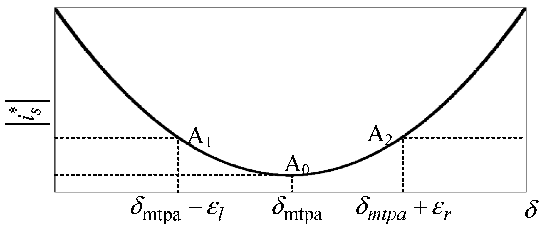
First, we analyze the stability of the SMESC-MTPA control scheme, using the current vector angle as the search variable. The ε-neighborhood is defined as shown in Figure 5, where Point A1 has a gradient of -ρ/k, Point A2 has a gradient of ρ/k, and Point A0 (the minimum point) has a gradient of 0. The horizontal coordinates (current vector angles) of A0, A1, and A2 are δmtpa, δmtpa-εl, and δmtpa+εl, respectively. Thus, the ε-neighborhood of the optimum point is formally defined as the following:
Θ ε l , ε r * = δ | δ mtpa ε l δ δ mtpa + ε r
For the first phase, before entering the ε-neighborhood of the optimal point, the derivative of the stator current magnitude with respect to δ satisfies the following:
d i s * d δ > ρ k
By denoting the derivative of the stator current magnitude with respect to δ as υ, the switching function is reconstructed as follows:
η n t = s t 2 N + 1 α , υ 0 s t 2 N α , υ < 0
where N is an integer satisfying the following:
N = r o u n d s t 2 α 1 , υ 0 r o u n d s t 2 α 1 2 , υ < 0
Here, the function round denotes rounding up to the nearest integer, while ηₙ(t) is bounded within the range (−α, α).
The sign of the new switching function can be calculated as follows:
sgn η n t = sgn υ sgn sin π s α
The derivative expression of the new switching function is given as follows:
η ˙ n t = s ˙ t = k sgn sin π s α υ ρ
According to Equation (18), Equation (19) can be simplified as follows:
η ˙ n t = k sgn η n t υ ρ
The Lyapunov function is defined as follows:
V = 0.5 η n 2 t
Thus, we obtain the following:
V ˙ = η n t η ˙ n t = η n t k υ + ρ sgn η n t
Based on Equation (20), Equation (21) satisfies the following condition:
V ˙ < 0
According to the Lyapunov stability theorem, the SMESC-MTPA control system is stable before entering the ε-neighborhood of the optimal operating point.
For the second phase, after entering the ε-neighborhood of the optimal point, the derivative of the current magnitude with respect to δ (denoted as υ) no longer satisfies Equation (22), i.e.:
υ ρ k
Within the ε-neighborhood of the optimal point, the sliding-mode extremum seeking algorithm essentially performs the extremum search by incrementally adjusting δ (either increasing or decreasing it). Over one complete cycle of the switching function s(t), the total variation in δ can be calculated as follows:
Δ δ = 2 α k 2 υ ρ 2 k υ 2
From Equations (23) and (24), the following conclusions can be drawn:
When υ > 0, Δ δ < 0;
When υ < 0, Δ δ > 0.
Therefore, within the ε-neighborhood of the optimal point, the sliding-mode extremum seeking algorithm achieves convergence to the minimum point by controlling the variation in δ, ultimately realizing MTPA control.
In summary, the stability of the SMESC-MTPA control method—which utilizes the current vector angle as the search variable—has been rigorously proven for both operational phases.

3.2. Convergence Processes and Control Accuracy

Additionally, to analyze the control performance of the SMESC-MTPA method, using the current vector angle as the search variable, a detailed quantitative analysis will be conducted from two key aspects: convergence speed and control accuracy.
The analysis of convergence speed can be divided into three distinct phases. The first phase is to enter the sliding surface from the initial state, the second phase is before entering the optimal ε-neighborhood, and the third phase is after entering the optimal ε-neighborhood.
According to Equation (22), the SMESC-MTPA control will reach the sliding surface within a finite time before entering the ε-neighborhood of the optimal point. The time required to reach the sliding surface from the initial state can be calculated as follows:
Δ t 0 = i s _ * 0 n α ρ
In the equation, i*s_0 represents the initial value of the stator current. The sliding surface is defined as follows:
η n t = 0
Therefore, on the sliding surface, the following condition holds the following:
s t = η n t + 2 N + 1 α , υ 0 η n t + 2 N α ,       υ < 0
After reaching the sliding surface, the switching function s(t) can be considered constant within an allowable error margin. The rate of change in the current magnitude under this condition is given by the following:
d i s * d t = ρ
Since ρ is negative, the current amplitude will continuously decrease during the search process on the sliding surface, driving the system toward the MTPA operating point. Clearly, the convergence speed on the sliding surface is directly proportional to the absolute value of ρ. The larger the absolute value of ρ, the faster the convergence rate in this phase.
After entering the ε-neighborhood of the optimal point, the absolute value of the total variation in δ within a single period of the switching function s(t) can be expressed as the following:
Δ δ = 2 α υ ρ 2 / k 2 υ 2
Once the ε-neighborhood is determined, the ratio between parameters ρ and k is fixed. Furthermore, according to Equation (29), after entering the ε-neighborhood of the optimal point, a larger parameter, α, leads to faster convergence speed. The control accuracy of the SMESC-MTPA method can be calculated by the following expression:
ε * = k α / 2 ρ

4. Simulation Analysis and Experimental Verification

4.1. Simulation Analysis

In order to verify the effectiveness of the proposed method, a simulation model was built in MATLAB 2022a, and the main parameters of the motor are shown in Table I. In addition, the moment of inertia of the IPMSM is 0.001. Search results of the current vector angle with the proposed method under different load torque conditions are shown in Figure 6, where the parameters of the SMES-MTPA are set as ρ = 0.8 ,   k = 0.8 ,   α = 0.005 .
In Figure 6, Tl and TN represent the load torque and rated torque, respectively. The results in Figure 6 indicate that the current vector angle values, obtained by using the method proposed in this paper under different load torques, are basically consistent with the theoretical values, indicating that the proposed method is stable and the search results can converge to near its theoretical value. In Figure 6, the maximum load torque is set to 1.2 times the rated torque, taking into account an overload of 20%. Figure 6 shows that the proposed method can still achieve accurate tracking of MTPA operating points under motor overload conditions.
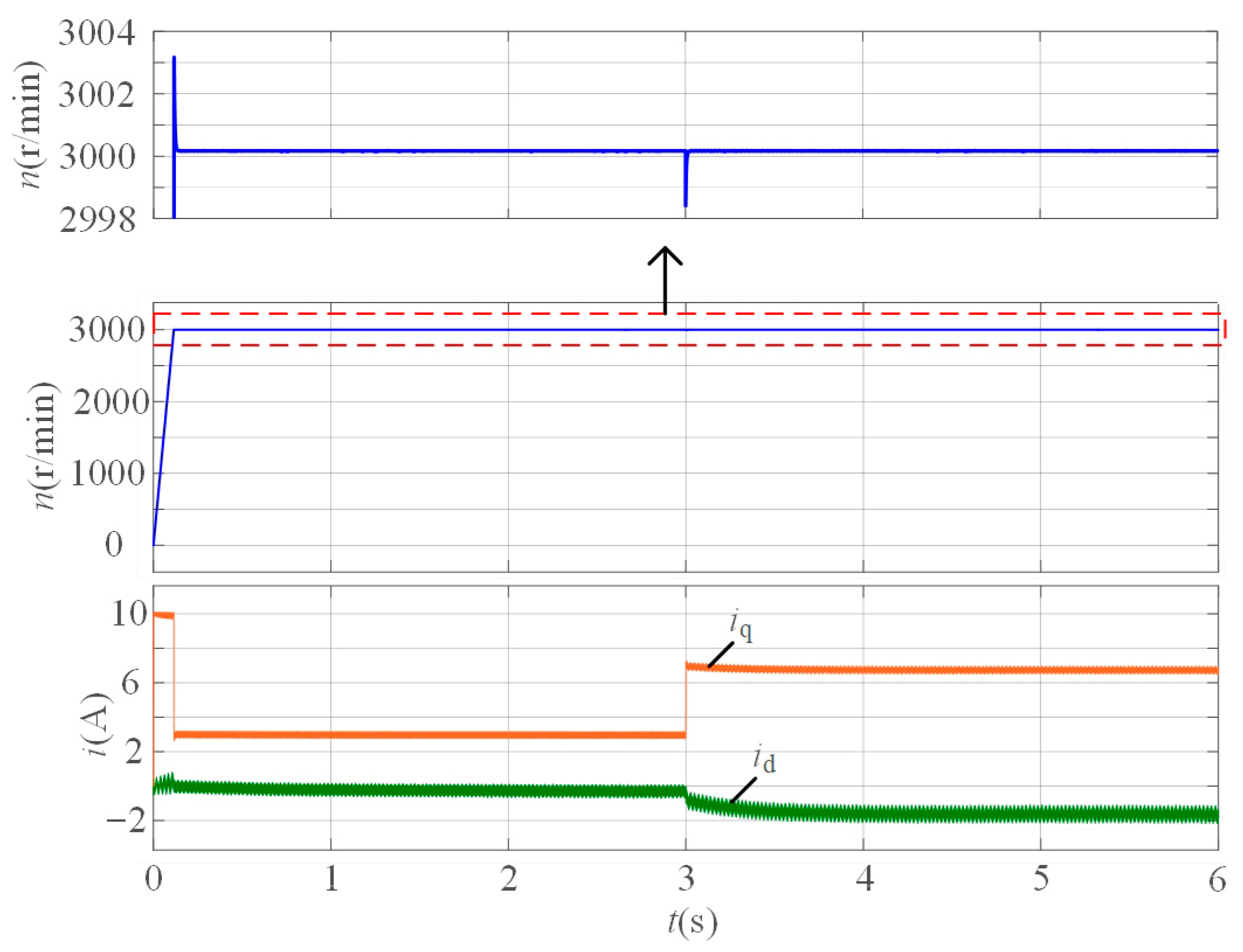
In order to analyze the dynamic performance of the proposed method, Figure 7 shows the experimental results of the motor, starting from static to 3000 r/min, and the load torque changing step-by-step, from 50% rated torque to 50% rated torque. The results in Figure 7 indicate that during the start-up process, the speed steadily increases, and the speed overshoot does not exceed 4 r/min. However, under the condition of a large increase in load torque, the speed drop does not exceed 2 r/min. Therefore, the proposed method has excellent dynamic performance.

4.2. Experimental Verification

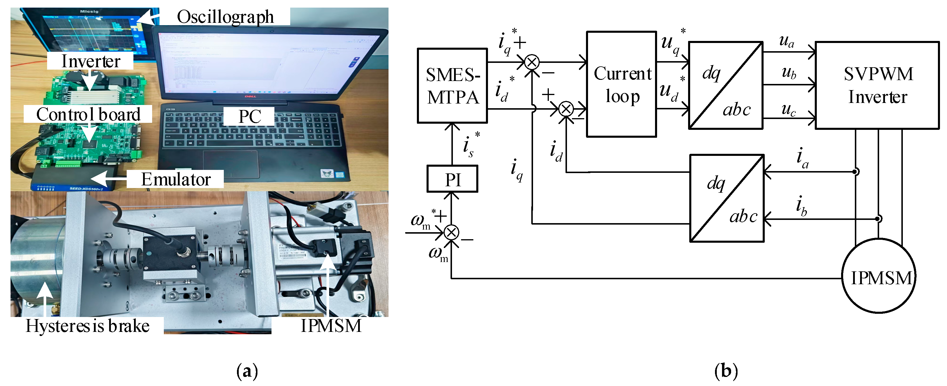
The experiments were conducted on the test platform depicted in Figure 8a. The test platform consists of the voltage source inverter (VSI) and the motor test platform. The control algorithm is executed through a digital signal processing (DSP) chip of type TMS320F28335. The parameters of the tested IPMSM are listed in Table I. In this algorithm, the pulse width modulation (PWM) frequency and the sampling frequency are both 10 kHz. The control block diagram for the system with SMES-MTPA is shown in Figure 8b. In Figure 8b, the current inner loop employs a proportional integral-based decoupling controller, whose control response speed is significantly faster than the search speed of the SMES. The final obtained values of the SMES-MTPA are the d-axis and q-axis current reference values under MTPA conditions, and the current command is tracked through vector control.
The experimental results of the proposed MTPA with ρ = −0.8, k = 0.8, and α = 0.005 are shown in Figure 9. In Figure 9, the motor speed reference value is 1000 r/min and the load torque is set as 2.0 N.m. In the search process, the state of id = 0 is set as the initial state given. In the search process, the stator current vector angle increases from 90 degrees to 100.93 degrees, and the stator current amplitude decreases from 0.847 p.u. to 0.815 p.u. In this working condition, the theoretical value of the stator current vector angle is 100.98 degrees. Accordingly, the searching value of the stator current vector angle is almost the same as the theoretical value, and the proposed MTPA method can accurately track the MTPA point. Compared with id = 0 control, the current amplitude is reduced by 3.8%, and the inverter loss and motor copper loss of the system are reduced correspondingly, which is beneficial to improve the system efficiency. In addition, the whole search process with ρ = −0.8, k = 0.8, and α = 0.005 takes 0.36s, as shown in Figure 9, which is fast.
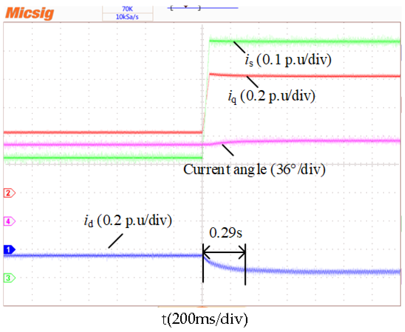
Figure 10 gives the experimental results of the SMESC-MTPA, with the load torque mutation process between 1 N.m and 2 N.m. With the load torque set as 1 and 2 N.m, the theoretical values of the stator current vector angles are 96.0 and 100.98 degrees. With the load torque set as 1 and 2 N.m, the searching values of the stator current vector angles are 96.1 and 100.93 degrees. In addition, the searching process, as shown in Figure 10, only takes 0.29 s. Accordingly, the results show that the search process of SMESC-MTPA is fast and stable under the load torque’s sudden increase and sudden decrease conditions.
The error analysis of the searching angles with different angles are shown in Table 2. It is indicated that the theoretical value is close to the actual value, which shows that the proposed MTPA method can achieve high-precision tracking of the operating point of the MTPA.

5. Conclusions

A novel MTPA method is proposed, and the stability, convergence speed, and control accuracy are studied in detail. The proposed MTPA can obtain the MTPA working points without knowing any motor parameters, and it does not require either a high-frequency injecting signal or high-pass and low-pass filters in the process of angle searching. The experimental results demonstrate that the proposed MTPA method can automatically search for the current vector angle online, with the maximum error in searching for the current angle not exceeding 2%, and the search speed is rapid.

Author Contributions

Conceptualization, X.W. and Z.Z.; methodology, X.W.; software, Z.Z. and B.Y.; validation, Z.Z. and B.Y.; formal analysis, X.W.; investigation, Z.Z. and X.W.; resources, B.Y.; data curation, Z.Z.; writing—original draft preparation, Z.Z.; writing—review and editing, X.W.; visualization, Z.Z.; supervision, B.Y.; project administration, X.W.; funding acquisition, X.W. All authors have read and agreed to the published version of the manuscript.

Funding

This work was supported in part by the National Natural Science Foundational of China under Grant 52007190.

Data Availability Statement

Part of the data can be obtained by contacting the corresponding author.

Conflicts of Interest

Author Z.Z. and B.Y. were employed by the company Jiangsu Guochuan Electric Co., Ltd. The remaining authors declare that the research was conducted in the absence of any commercial or financial relationships that could be construed as a potential conflict of interest.

References

  1. Yu, Y.; Cong, L.; Tian, X.; Xie, R.; Lu, J. Stator Current Vector Orientation-Based Backstepping Predictive Control of Torque Ripple Minimization for PMSM with consideration of Electrical Loss. Math. Probl. Eng. 2020, 2020, 7319329. [Google Scholar] [CrossRef]
  2. Hu, D.; Xu, L. Characterizing the torque lookup table of an IPM machine for automotive application. In Proceedings of the 2014 IEEE Transportation Electrification Conference and Expo, Asia-Pacific (ITEC Asia-Pacific), Xi’an, China, 31 August–3 September 2014; IEEE: New York, NY, USA, 2014; pp. 1–6. [Google Scholar]
  3. Miao, Y.; Ge, H.; Preindl, M.; Ye, J.; Cheng, B.; Emadi, A. MTPA fitting and torque estimation technique based on a new flux-linkage model for interior-permanent-magnet synchronous machines. IEEE Trans. Ind. Appl. 2017, 53, 5451–5460. [Google Scholar] [CrossRef]
  4. Pan, C.T.; Sue, S.M. A linear maximum torque per ampere control for IPMSM drives over full-speed range. IEEE Trans. Energy Convers. 2005, 20, 359–366. [Google Scholar] [CrossRef]
  5. Özçiflikçi, O.E.; Koç, M.; Bahçeci, S. Evaluation of Maximum Torque per Ampere Control Method for Interior Permanent Magnet Machine Drives on dSpace with Emphasis on Potential Practical Issues for High Energy Efficiency. Energies 2025, 18, 4118. [Google Scholar] [CrossRef]
  6. Dianov, A.; Tinazzi, F.; Calligaro, S.; Bolognani, S. Review and Classification of MTPA Control Algorithms for Synchronous Motors. IEEE Trans. Power Electron. 2022, 37, 3990–4007. [Google Scholar] [CrossRef]
  7. Rabiei, A.; Thiringer, T.; Alatalo, M.; Grunditz, E.A. Improved maximum-torque-per-ampere algorithm accounting for core saturation, cross-coupling effect, and temperature for a PMSM intended for vehicular applications. IEEE Trans. Transp. Electrif. 2016, 2, 150–159. [Google Scholar] [CrossRef]
  8. Jena, M.R.; Mohanty, K.B. MTPA Control of IPMSM with Self-Correction of Parameters Equivalent Base Current. IEEE Trans. Energy Convers. 2025, 40, 1750–1762. [Google Scholar] [CrossRef]
  9. Jung, H.-S.; Kim, H.; Sul, S.-K.; Berry, D.J. Temperature Estimation of IPMSM by Using Fundamental Reactive Energy Considering Variation of Inductances. IEEE Trans. Power Electron. 2021, 36, 5771–5783. [Google Scholar] [CrossRef]
  10. Hu, Z.; Zhan, J.; Li, Z.; Hou, X.; Fu, Z.; Yang, X. Enhanced Raccoon Optimization Algorithm for PMSM Electrical Parameter Identification. Energies 2025, 18, 869. [Google Scholar] [CrossRef]
  11. ZXia, Z.; Nalakath, S.; Tarvirdilu-Asl, R.; Sun, Y.; Wiseman, J.; Emadi, A. Online Optimal Tracking Method for Interior Permanent Magnet Machines with Improved MTPA and MTPV in Whole Speed and Torque Ranges. IEEE Trans. Power Electron. 2020, 35, 9753–9769. [Google Scholar] [CrossRef]
  12. Qiu, Z.-H.; Lai, Y.-S. New On-Line MTPA Angle Search and Control Methods Based on Digital Twins for IPM Synchronous Motor Drives Considering Motor Non-Linearity. IEEE Access 2023, 11, 146185–146193. [Google Scholar] [CrossRef]
  13. Kim, S.; Yoon, Y.D.; Sul, S.K.; Ide, K. Maximum torque per ampere (MTPA) control of an IPM machine based on signal injection considering inductance saturation. IEEE Trans. Power Electron. 2013, 28, 488–497. [Google Scholar] [CrossRef]
  14. Li, K.; Sun, T.; Liang, J.; Koc, M.; Zhou, Y. Automatic MTPA Control for IPMSM Drives Based on Pseudorandomly Reversed Fixed-Frequency Sinusoidal Signal Injection. IEEE Trans. Ind. Electron. 2024, 71, 6863–6874. [Google Scholar] [CrossRef]
  15. Chen, Z.; Yan, Y.; Shi, T.; Gu, X.; Wang, Z.; Xia, C. An Accurate Virtual Signal Injection Control for IPMSM with Improved Torque Output and Widen Speed Region. IEEE Trans. Power Electron. 2021, 36, 1941–1953. [Google Scholar] [CrossRef]
  16. Sun, T.; Long, L.; Yang, R.; Li, K.; Liang, J. Extended Virtual Signal Injection Control for MTPA Operation of IPMSM Drives with Online Derivative Term Estimation. IEEE Trans. Power Electron. 2021, 36, 10602–10611. [Google Scholar] [CrossRef]
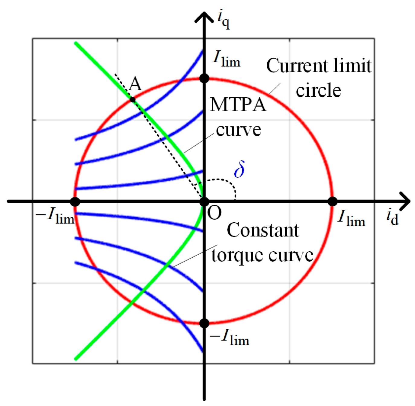
Figure 1. Schematic diagram of the angle of the stator current vector.
Energies 18 05613 g001
Figure 2. Constant torque curves in the polar coordinates.
Energies 18 05613 g002
Figure 3. Curves of derivative of current amplitude to angle.
Energies 18 05613 g003
Figure 4. SMESC-MTPA control block diagram with current vector angle as search variable.
Energies 18 05613 g004
Figure 5. Nearest ε-neighborhood of the SMESC-MTPA with δ as the searching variable.
Energies 18 05613 g005
Figure 6. Search results of current vector angle under different load torque conditions.
Energies 18 05613 g006
Figure 7. Dynamic simulation results.
Energies 18 05613 g007
Figure 8. Experiment platform and the control block diagram. (a) Photo of the experimental platform, (b) control block diagram for the system.
Energies 18 05613 g008
Figure 9. Experimental results of the proposed MTPA ( ρ = 0.8 ,   k = 0.8 ,   α = 0.005 ).
Energies 18 05613 g009
Figure 10. Experimental results of the proposed MTPA with the load torque’s sudden change.
Energies 18 05613 g010
Table 1. Main parameters of the IPMSM.
ParameterValueParameterValue
pole pairs (pn)5rotor flux (ψf)0.053 Wb
stator resistance (R)0.93 Ωdc-link voltage (Udc)311 V
stator inductance (Ld/Lq)4.03/6.24 mHswitching frequency (fc)10 kHz
rated speed3000 r/minrated power750 W
Table 2. Error analysis of the searching angles.
Load Torque/N.mTheoretical Value/DegreeSearching Value/DegreeError Value/%
0.492.391.21.2
0.894.993.81.2
1.297.095.21.9
1.699.098.20.8
2.0100.98100.930.05
Disclaimer/Publisher’s Note: The statements, opinions and data contained in all publications are solely those of the individual author(s) and contributor(s) and not of MDPI and/or the editor(s). MDPI and/or the editor(s) disclaim responsibility for any injury to people or property resulting from any ideas, methods, instructions or products referred to in the content.