Article

An Accurate Method for Designing Piezoelectric Energy Harvesters Based on Two-Dimensional Green Functions Under a Tangential Line Force

1
School of Robotics, Guangdong Polytechnic of Science and Technology, Zhuhai 519090, China
2
Beijing Xinghang Mechanical-Electric Equipment Co., Ltd., Beijing 100074, China
3
Department of Engineering Mechanics, Hunan University, Changsha 410082, China
*
Author to whom correspondence should be addressed.
Energies 2025, 18(21), 5564; https://doi.org/10.3390/en18215564 (registering DOI)
Submission received: 5 September 2025 / Revised: 3 October 2025 / Accepted: 14 October 2025 / Published: 22 October 2025

Abstract

The piezoelectric coating structure constitutes the main configuration of contemporary energy harvesting systems, and its development requires accurate modeling of electromechanical coupling behavior under mechanical loads. The present work prepares a framework to analyze orthotropic piezoelectric coating–substrate systems; based on the fundamental solution theory, it derives two-dimensional Green functions from closed-form elementary functions. The formulation can establish the mesh-free solution paradigm through addressing tangential line force loading onto a coated surface. This method helps reconstruct full-field electromechanical responses upon arbitrary mechanical loading by integrating superposition principles and Gaussian quadrature technologies. An important application is in optimizing coating thickness, where parametric research suggests that piezoelectric layer geometry is non-linearly correlated with energy conversion efficiency. Notably, analytical sensitivity coefficients of this framework contribute to gradient-based optimization algorithms, which enhances efficiency compared with traditional empirical frameworks.

1. Introduction

Energy harvesting technologies have garnered substantial research interest as sustainable power sources for autonomous microsystems [1]. Methods have been proposed for high-speed railway infrastructure, illustrating broad applicability [2]. Piezoelectric transduction is especially prevalent owing to its high electromechanical coupling and straightforward implementation [3]. Triboelectric generators offer an alternative mechanism for mechanical energy harvesting [4]. Advanced materials such as MXene-based nanostructures are being explored for high-performance piezoelectric/triboelectric harvesters [5]. Human motion-based electrochemical energy harvesting also represents an active research avenue [6]. The integration of energy harvesting into storage systems has been highlighted in recent studies on energy-autonomous microsystems for enhanced piezoelectricity [7].
Hybrid pendulum–triboelectric generator configurations developed by Chen et al. [8] produced 23 times more power than the no-swing case. Galloping cantilever harvesters with V-shaped attachments were used to improve low-speed wind energy capture to optimize aerodynamic effects in a study of Cao et al. [9]. Biomimetic swallowtail-shaped attachments have been proposed in the research of Zhou et al. [10] to enhance wind-driven harvesting efficiency, yielding a ≈ 7.16-fold increase in power output. Excited piezoelectric wind harvesters with dual bluff-body exciters have also been demonstrated, with the maximum output voltage of 90.35 V [11]. Similarly, magnetically tunable clamping mechanisms have enabled adjustable resonance in rotational piezoelectric harvesters for achieving maximal power (9.95 mW) [12]. Robustness under environmental conditions has been considered, with the performance of piezoelectric harvesters analyzed in actual rain [13]. Optimized impedance matching and mechanism designs have been applied to human-motion-driven piezoelectric harvesters [14]. Techniques to broaden the operating bandwidth include PVDF film harvesters exploiting mechanical beating effects with the maximum power of 19.84 W [15,16]. At the nanoscale, ZnO nanowire arrays have been utilized in piezoelectric nanogenerators for low-frequency energy sources [17]. Flow-induced vibrations in wavy cylinders and tuned mass dampers have been analyzed for energy generation, as developed by Zhao et al. [18]. Wave propagation analysis in piezoelectric NEMS structures has been performed to understand micro-scale harvester behavior [19]. Nonvibrational modes such as twisting vibration of suspended rotors have also been harnessed for energy harvesting [20]. Directional harvesting strategies that align the transducer with the airflow in pipeline devices have been developed [21].
Innovative structures like L-shaped cantilever beams with frequency up-conversion have been designed by Zhang et al. for ultralow-frequency vibrations [22]. Flexible piezoelectric ring generators have been fabricated for wearable energy harvesting applications [23] and early experimental studies have characterized piezoelectric ring energy harvesters [24]. These varied developments highlight the importance of precise modeling of layered piezoelectric devices under mechanical loading [25,26].
The finite element method (FEM) is extensively utilized as the numerical approach for modeling complex piezoelectric and orthotropic structures [27]. Its maturity and flexibility make FEM the default tool for engineering analyses of anisotropic materials [28]. However, the extremely low thickness of piezoelectric coatings necessitates highly refined meshes in FEM, which increases the computational effort [29]. Even fine meshes struggle to capture the steep stress and electric field gradients in the coating [30]. The coating–substrate interface exhibits discontinuous stress components that violate FEM’s continuity assumptions [31]. As a result, FEM solutions often show large errors near the interface [32]. Interfacial inaccuracies can have serious implications. Mis-predicted stresses may lead to premature coating failure in thermal protection systems [33]. The limitations of FEM in addressing thin coatings and interface behavior have motivated the development of alternative solution strategies.
Generalized analytical methods derive closed-form solutions for layered media by satisfying the governing equations through harmonic or exponential functions [34]. Zhang et al. used the fundamental solution theory and formulated two-dimensional Green functions for coated substrates under various loading conditions [35]. A two-dimensional Green function for an orthotropic piezoelectric coating upon tangential line force was derived by Shang et al. recently [36] and enables mesh-free analysis of arbitrary loads. Similarly, Green functions have been obtained for isotropic double-layer structures under concentrated surface loads by Li et al. [37]. Dedicated analytical solutions also exist for specific contact problems. The cylindrical indenter loading on coated media has been solved by Tong et al. [38]. Penny-shaped crack problems in piezoelectric-coated materials have been addressed analytically by Hou et al. [39]. Sliding frictional contact on piezoelectric-coated substrates has likewise been modeled in closed form by Tong et al. [40]. These analytical formulations eliminate mesh dependency and afford direct parametric differentiation.
In this work, a novel framework to analyze orthotropic piezoelectric coating–substrate systems subject to tangential line forces is presented. The closed-form two-dimensional Green functions in terms of elementary functions via the general solution are derived. The resulting formulation enables full-field electromechanical responses to be reconstructed via superposition and Gauss integration in a mesh-free manner, which can yield the rapid computation of displacement, stress, and electric fields under arbitrary surface loading. Its accuracy has been rigorously validated against the Scarborough criterion with error tolerance, which ensures that numerical results maintain correctness to at least m significant digits and demonstrate high computational precision. The approach is illustrated through parametric studies on coating thickness and geometry, which reveal non-linear effects on energy conversion efficiency. Moreover, analytical sensitivity expressions are obtained, which are helpful for the design and analysis of thin-film piezoelectric devices.

2. General Solutions to Orthotropic Piezoelectric and Elastic Materials

2.1. General Solutions to Orthotropic Piezoelectric Materials

In an electro-elastic field where each component is independent of the y-coordinate, a plane problem in two-dimensional Cartesian coordinates x ,   z arises. If piezoelectric materials are polarized along the z-axis, constitutive equations for orthotropic materials are determined by the constitutive equations given in Equation (1).
σ x = c 11 u x + c 13 w z + e 31 ϕ z σ z = c 13 u x + c 33 w z + e 33 ϕ z τ z x = c 44 u z + w x + e 15 ϕ x D x = e 15 u z + w x ε 11 ϕ x D z = e 31 u x + e 33 w z ε 33 ϕ z
in which u and w represent the mechanical displacement components along the x and z directions, respectively. σ m , τ m n , and D m ( m , n = x ,   z ) are the stress and electric displacement components, respectively. ϕ refers to the electric potential. c i j , e i j , and ε i j ( i , j = 1 ,   3 ,   4 ) stand for the elastic, piezoelectric, and dielectric constant, respectively.
The mechanical equilibrium equations in the absence of body forces are given in Equation (2).
σ x x + τ z x z = 0 τ z x x + σ z z = 0 D x x + D z z = 0
A compact general solution satisfying Equations (1) and (2) was proposed by Ding et al. [41] and is presented in Equation (3).
u = j = 1 3 ψ j x w = j = 1 3 s j k 1 j ψ j z j   ϕ = j = 1 3 s j k 2 j ψ j z j σ x = j = 1 3 s j 2 ω 1 j 2 ψ j z j 2 σ z = j = 1 3 ω 1 j 2 ψ j z j 2 τ z x = j = 1 3 s j ω 1 j 2 ψ j x z j D x = j = 1 3 s j ω 2 j 2 ψ j x z j D z = j = 1 3 ω 2 j 2 ψ j z j 2
in which ψ j ( j = 1 ,   2 ,   3 ) represents three functions satisfying the harmonic equations below.
( 2 x 2 + 2 z j 2 ) ψ j = 0
z j = s j z   ( j = 1 ,   2 ,   3 ) and the parameter s j   ( j = 1 ,   2 ,   3 ) , satisfying R e ( s j ) > 0 , represent three eigenvalues for the sixth-degree polynomial as6bs4 + cs2d = 0, in which
a = c 44 e 33 2 + c 33 ε 33 b = c 33 c 44 ε 11 + e 15 + e 31 2 + ε 33 c 11 c 33 + c 44 2 c 13 + c 44 2 + e 33 2 c 44 e 15 + c 11 e 33 2 c 13 + c 44 e 15 + e 31 c = c 44 c 11 ε 33 + e 15 + e 31 2 + ε 11 c 11 c 33 + c 44 2 c 13 + c 44 2 + e 15 2 c 11 e 33 + c 44 e 15 2 c 13 + c 44 e 15 + e 31 d = c 11 e 15 2 + c 44 ε 11
In addition,
m 1 = ( c 13 + c 44 ) ε 11 + ( e 15 + e 31 ) e 15 m 2 = ( c 13 + c 44 ) ε 33 + ( e 15 + e 31 ) e 33 m 3 = c 11 ε 33 + c 44 ε 11 + ( e 15 + e 31 ) 2 m 4 = c 13 e 33 c 13 ( e 15 + e 31 ) c 44 e 31 k 1 j = ( c 11 ε 11 m 3 s j 2 + c 44 ε 33 s j 4 ) / s j 2 ( m 1 m 2 s j 2 ) k 2 j = ( c 11 e 15 m 4 s j 2 + c 44 e 33 s j 4 ) / s j 2 ( m 1 m 2 s j 2 ) ω 1 j = c 44 + c 44 k 1 j + e 15 k 2 j ω 2 j = e 15 + e 15 k 1 j ε 11 k 2 j
Note that solution (3) applies only when the eigenvalue s j ( j = 1 ,   2 ,   3 ) is distinct, which is the common situation.

2.2. General Solution for Orthotropic Elastic Material

In an elastic field, when each of the components is not dependent on coordinate y, a plane problem in two-dimensional Cartesian coordinates (x, z) will occur. If the material has principal axes along x and z, constitutive equations for orthotropic materials are given in Equation (7).
σ x = c 11 u x + c 13 w z σ z = c 13 u x + c 33 w z τ z x = c 44 u z + w x
with u and w referring to mechanical displacement components along the x and z axes, respectively; σ x and σ z standing for the normal stress components down the x- and z-axes; τ z x indicating the shear stress component; and c i j ( i , j = 1 ,   3 ,   4 ) representing the elastic moduli.
Mechanical equilibrium equations without body forces are listed in Equation (8).
σ x x + τ z x z = 0 τ z x x + σ z z = 0
Hou et al. [42] proposed a compact general solution that satisfies Equations (7) and (8), as given in Equation (9).
u = i = 1 2 ψ i x w = i = 1 2 s i k i ψ i z i σ x = i = 1 2 s i 2 ω i 2 ψ i z i 2   σ z = i = 1 2 ω i 2 ψ i z i 2 τ z x = i = 1 2 s i ω i 2 ψ i x z i
where ψ i in Equation (9) still satisfies the following harmonic equation of Equation (10).
2 x 2 + 2 z i 2 ψ i = 0                           ( i = 1 , 2 )
z i = s i z , s i   ( i = 1 ,   2 ) , satisfying R e ( s i ) > 0 , account for two eigenvalues for the fourth-degree polynomial as4bs2 + c′ = 0, in which
a = c 33 c 44 b = c 11 c 33 + c 44 2 c 13 + c 44 2 c = c 11 c 44 κ 1 i = c 13 + c 44 κ 2 i = c 11 + c 44 s i 2 k i = κ 2 i s i 2 κ 1 i ω i = c 44 ( 1 + k i )
Notably, the general solution (9) is valid only for distinct eigenvalues s i   ( i   =   1 ,   2 ) , as is commonly the case.
For an electric field in a dielectric material, the constitutive relation in the two-dimensional Cartesian coordinate system (x, z) is given in Equation (12).
D z = ε z ϕ z D x = ε x ϕ x
in which D m ( m , n = x ,   z ) stands for the electric displacement components; ϕ denotes the electric potential; and ε z and ε x represent dielectric constants. The typical electric equilibrium equation is given as Equation (13).
D x x + D z z = 0
Substituting Equation (12) into Equation (13) yields Equation (14).
ε x 2 ϕ 2 x + ε z 2 ϕ 2 z = 0
For the convenience of constructing the solution, the function ψ ϕ is introduced.
ϕ = s ϕ ψ ϕ z ϕ
where s ϕ = ε x / ε z , z ϕ = s ϕ z , ψ ϕ from Equation (15) meets the harmonic equation below.
2 x 2 + 2 z ϕ 2 ψ ϕ = 0
Substituting Equation (15) in Equation (12) generates Equation (17):
D z = ε x 2 ψ ϕ z ϕ 2 D x = s ϕ ε x 2 ψ ϕ z ϕ x
Therefore, the general solutions given by Equations (3), (9), (15) and (17) will be used below.

3. Green Function for the Tangential Line Force onto Orthotropic Piezoelectric-Coated Structure Surface

Figure 1 shows a piezoelectric-coated structure that combines an orthotropic piezoelectric coating with an orthotropic substrate (electrical conductor or dielectric). The system is modeled as an infinite piezoelectric plate 0 z h , whose interface z = 0 and surface   z = h are perfectly bonded to a semi-infinite substrate z 0 . When a normal line force P z is applied to the surface at (0, h), the resulting electro-elastic field is determined using the general solutions given in Equations (3), (9), (15) and (17).
The boundary conditions for the traction-free surface z = h are given in Equation (18):
σ z ( x , h ) = 0 τ z x ( x , h ) = 0 D z ( x , h ) = 0
After considering the equilibrium of the infinite layer 0 z h   ( 0 < ε < h ) , the equation must satisfy the condition below.
+ τ z x ( x , ε ) d x + P x = 0
It is assumed that both the semi-infinite substrate   z 0 and the coating 0 z h are perfectly bonded. The compatibility conditions at the interface   z = 0 are given in Equation (20).
For interface z = 0 , the compatibility conditions are shown in Equation (20).
u ( x , 0 ) = u ( x , 0 ) w ( x , 0 ) = w ( x , 0 ) σ z ( x , 0 ) = σ z ( x , 0 ) τ z x ( x , 0 ) = τ z x ( x , 0 ) D z ( x , 0 ) = D z ( x , 0 ) ϕ ( x , 0 ) = ϕ ( x , 0 )
in which primed quantities denote variables of the semi-infinite substrate z 0 , whereas unprimed quantities refer to those in the coating material 0     z     h . To simplify notation, the following quantities are introduced in Equation (21).
z j = s j z z i = s i z z ϕ = s ϕ z h j = s j h h n k l = ( 2 n k ) h 1 + ( k l ) h 2 + ( l 1 ) h 3 z ¯ n j k l = z j h n k l R ¯ n j k l = x 2 + z ¯ n j k l 2 R ¯ n j k l * = R ¯ n j k l z ¯ n j k l z n j k l = z j + h n k l R n j k l = x 2 + z n j k l 2 R n j k * = R n j k l + z n j k l z n i k l = z i h n k l R n i k l = x 2 + z n i k l 2 R n i k l * = R n i k l z n i k l z n ϕ k l = z ϕ h n k l R n ϕ k l = x 2 + z n ϕ k l 2 R n ϕ k l * = R n ϕ k l z n ϕ k l ( n = 1 , 2 , , ;   j = 1 , 2 , 3 ;   i = 1 , 2 ,   k = 1 , 2 , , 2 n ;   l = 1 , 2 , , k )
where z j is determined by Equation (21); s i stands for material eigenvalues for the semi-infinite substrate z 0 .
Harmonic functions for the coating material 0 z h are given below.
ψ j = n = 1 ( ψ ¯ n j + ψ n j )                   ( j = 1 ,   2 ,   3 )
where
ψ ¯ n j = k = 1 2 n l = 1 k B ¯ n j k l x ( ln R ¯ n j k l 1 ) + z ¯ n j k l arctan x z ¯ n j k l ψ n j = k = 1 2 n l = 1 k B n j k l x ( ln R n j k l 1 ) + z n j k l arctan x z n j k l ( n = 1 , 2 , , ;   j = 1 , 2 , 3 ;   i = 1 , 2 ,   k = 1 , 2 , , 2 n ;   l = 1 , 2 , , k )
B ¯ n j k l and B n j k l are constants to be determined; R ¯ n j k l * and R n j k l * can be determined by Equation (21).
By substituting Equations (22) and (23) into the general solution given in Equation (3), the corresponding electro-elastic field is obtained.
u = n = 1 ( u ¯ n + u n )   w = n = 1 ( w ¯ n + w n ) σ x = n = 1 ( σ ¯ x n + σ x n )   σ z = n = 1 ( σ ¯ z n + σ z n ) τ z x = n = 1 ( τ ¯ z x n + τ z x n ) ϕ = n = 1 ϕ ¯ n + ϕ n D z = n = 1 D ¯ z n + D z n D x = n = 1 D ¯ x n + D x n
in which
u ¯ n = j = 1 3 k = 1 2 n l = 1 k B ¯ n j k l ln R ¯ n j k l u n = j = 1 3 k = 1 2 n l = 1 k B n j k l ln R n j k l w ¯ n = j = 1 3 k = 1 2 n l = 1 k s j k 1 j B ¯ n j k l arctan x z ¯ n j k l w n = j = 1 3 k = 1 2 n l = 1 k s j k 1 j B n j k l arctan x z n j k l σ ¯ x n = j = 1 3 k = 1 2 n l = 1 k s j 2 ω 1 j B ¯ n j k l x R ¯ n j k l 2 σ x n = j = 1 3 k = 1 2 n l = 1 k s j 2 ω 1 j B n j k l x R n j k l 2 σ ¯ z n = j = 1 3 k = 1 2 n l = 1 k ω 1 j B ¯ n j k l x R ¯ n j k l 2 σ z n = j = 1 3 k = 1 2 n l = 1 k ω 1 j B n j k l x R n j k l 2 τ ¯ z x n = j = 1 3 k = 1 2 n l = 1 k s j ω 1 j B ¯ n j k l z ¯ n j k l R ¯ n j k l 2 τ z x n = j = 1 3 k = 1 2 n l = 1 k s j ω 1 j B n j k l z n j k l R n j k l 2 ϕ ¯ n = j = 1 3 k = 1 2 n l = 1 k s j k 2 j B ¯ n j k l arctan x z ¯ n j k l ϕ n = j = 1 3 k = 1 2 n l = 1 k s j k 2 j B n j k l arctan x z n j k l D ¯ z n = j = 1 3 k = 1 2 n l = 1 k ω 2 j B ¯ n j k l x R ¯ n j k l 2   D z n = j = 1 3 k = 1 2 n l = 1 k ω 2 j B n j k l x R n j k l 2 D ¯ x n = j = 1 3 k = 1 2 n l = 1 k s j ω 2 j B ¯ n j k l z ¯ n j k l R ¯ n j k l 2   D x n = j = 1 3 k = 1 2 n l = 1 k s j ω 2 j B n j k l z n j k l R n j k l 2 ( n = 1 , 2 , , )
For the semi-infinite substrate z 0 , the solution is assumed to be given by Equation (26):
ψ i = n = 1 ψ n i   i = 1 , 2 ψ ϕ = n = 1 ψ n ϕ
where
ψ n i = k = 1 2 n l = 1 k B n i k l x ( ln R n i k l 1 ) + z n i k l arctan x z n i k l ψ n ϕ = k = 1 2 n l = 1 k B n ϕ k l x ( ln R n ϕ k l 1 ) + z n ϕ k l arctan x z n ϕ k l ( n = 1 , 2 , , ;   i = 1 , 2 ;   k = 1 , 2 , , 2 n ;   l = 1 , 2 , , k )
B n i k l represents a constant to be determined; R n i k l * can be determined via Equation (21).
Substituting Equations (26) and (27) into the general solutions given in Equations (9), (15) and (17) yields Equation (28):
u = n = 1 u n w = n = 1 w n σ x = n = 1 σ x n σ z = n = 1 σ z n τ z x = n = 1 τ z x n ϕ = n = 1 ϕ n D z = n = 1 D z n         D x = n = 1 D x n
in which
u n = i = 1 2 k = 1 2 n l = 1 k B n i k l ln R n i k l w n = i = 1 2 k = 1 2 n l = 1 k s i k i B n i k l arctan x z n i k l σ x n = i = 1 2 k = 1 2 n l = 1 k s i 2 ω i B n i k l x R n i k l 2 σ z n = i = 1 2 k = 1 2 n l = 1 k ω i B n i k l x R n i k l 2 τ z x n = i = 1 2 k = 1 2 n l = 1 k s i ω i B n i k l z n i k l R n i k l 2 ϕ n = k = 1 2 n l = 1 k s ϕ B n ϕ k l arctan x z n ϕ k l D z n = k = 1 2 n l = 1 k ε x B n ϕ k l x R n ϕ k l 2 D x n = k = 1 2 n l = 1 k s ϕ ε x B n ϕ k l z n ϕ k l R n ϕ k l 2 ( n = 1 , 2 , , ;   i = 1 , 2 ;   k = 1 , 2 , , 2 n ;   l = 1 , 2 , , k )
Based on Equation (24), the boundary conditions of Equation (18) at the free surface ( σ ¯ z 1 ( x , h ) = 0 , τ ¯ z x 1 ( x , h ) = 0 , D ¯ z 1 ( x , h ) = 0 ) z = h can be written in the following form:
σ z n ( x , h ) + σ ¯ z ( n + 1 ) ( x , h ) = 0 τ z x n ( x , h ) + τ ¯ z x ( n + 1 ) ( x , h ) = 0 D z n ( x , h ) + D ¯ z ( n + 1 ) ( x , h ) = 0                         ( n =   1 , 2 , )
Based on Equations (24) and (28), the compatibility conditions (20) at the interface z = 0 are given below.
u ¯ n ( x , 0 ) + u n ( x , 0 ) = u n ( x , 0 ) w ¯ n ( x , 0 ) + w n ( x , 0 ) = w n ( x , 0 ) σ ¯ z n ( x , 0 ) + σ z n ( x , 0 ) = σ z n ( x , 0 ) τ ¯ z x n ( x , 0 ) + τ z x n ( x , 0 ) = τ z x n ( x , 0 ) D ¯ z n ( x , 0 ) + D z n ( x , 0 ) = D z n ( x , 0 ) ϕ ¯ n ( x , 0 ) + ϕ n ( x , 0 ) = ϕ n ( x , 0 )                     ( n =   1 , 2 , )
Substituting Equation (25) into Equation (30) produces Equation (32),
B ¯ 1121 = B ¯ 1122 = B ¯ 1211 = B ¯ 1222 = B ¯ 1311 = B ¯ 1321 = 0 ω 11 B ¯ 1111 + ω 12 B ¯ 1221 + ω 13 B ¯ 1322 = 0 ω 21 B ¯ 1111 + ω 22 B ¯ 1221 + ω 23 B ¯ 1322 = 0
as well as the following identities:
z ¯ ( n + 1 ) 1 ( 2 n + 2 ) λ ( h ) = h 1 ( 2 n + 2 λ ) h 2 ( λ 1 ) h 3 z ¯ ( n + 1 ) 2 λ λ ( h ) = ( 2 n + 2 λ ) h 1 + h 2 ( λ 1 ) h 3 z ¯ ( n + 1 ) 3 λ 1 ( h ) = ( 2 n + 2 λ ) h 1 ( λ 1 ) h 2 + h 3 ( n = 1 , 2 , , ;   λ = 1 , 2 , , 2 n + 2 )
z n 111 ( h ) = z ¯ ( n + 1 ) 111 ( h ) = z ¯ ( n + 1 ) 221 ( h ) = z ¯ ( n + 1 ) 322 ( h ) = 2 n h 1 z n 2 ( 2 n ) 1 ( h ) = z ¯ ( n + 1 ) 1 ( 2 n + 1 ) 1 ( h ) = z ¯ ( n + 1 ) 2 ( 2 n + 2 ) 1 ( h ) = z ¯ ( n + 1 ) 3 ( 2 n + 2 ) 2 ( h ) = 2 n h 2 z n 3 ( 2 n ) ( 2 n ) ( h ) = z ¯ ( n + 1 ) 1 ( 2 n + 1 ) ( 2 n + 1 ) ( h ) = z ¯ ( n + 1 ) 2 ( 2 n + 2 ) ( 2 n + 1 ) ( h )     = z ¯ ( n + 1 ) 3 ( 2 n + 2 ) ( 2 n + 2 ) ( h ) = 2 n h 3 z n 1 ( m + 1 ) 1 ( h ) = z n 2 m 1 ( h ) = z ¯ ( n + 1 ) 1 ( m + 1 ) 1 ( h ) = z ¯ ( n + 1 ) 2 ( m + 2 ) 1 ( h ) = z ¯ ( n + 1 ) 3 ( m + 2 ) 2 ( h ) = ( 2 n m ) h 1 + m h 2 z n 1 ( m + 1 ) ( m + 1 ) ( h ) = z n 3 m m ( h ) = z ¯ ( n + 1 ) 1 ( m + 1 ) ( m + 1 ) ( h ) = z ¯ ( n + 1 ) 2 ( m + 2 ) ( m + 1 ) ( h ) = z ¯ ( n + 1 ) 3 ( m + 2 ) ( m + 2 ) ( h ) = ( 2 n m ) h 1 + m h 3 z n 2 ( 2 n ) ( m + 1 ) ( h ) = z n 3 ( 2 n ) m ( h ) = z ¯ ( n + 1 ) 1 ( 2 n + 1 ) ( m + 1 ) ( h ) = z ¯ ( n + 1 ) 2 ( 2 n + 2 ) ( m + 1 ) ( h ) = z ¯ ( n + 1 ) 3 ( 2 n + 2 ) ( m + 2 ) ( h ) = ( 2 n m ) h 2 + m h 3 z n 1 ( α + 1 ) ( β + 1 ) ( h ) = z n 2 α ( β + 1 ) ( h ) = z n 3 α β ( h ) = z ¯ ( n + 1 ) 1 ( α + 1 ) ( β + 1 ) ( h ) = z ¯ ( n + 1 ) 2 ( α + 2 ) ( β + 1 ) ( h ) = z ¯ ( n + 1 ) 3 ( α + 2 ) ( β + 2 ) ( h ) = ( 2 n α ) h 1 + ( α β ) h 2 + β h 3 ( n = 1 , 2 , , ;   m = 1 , 2 , , 2 n 1 ;   α = 2 , 3 , , 2 n 1 ;   β = 1 , 2 , , α 1 )
Substituting Equation (25) into Equation (31) using Equation (34) yields Equations (35)–(38) for R n j k l ( x , h ) , R n j k l * ( x , h ) , R ¯ n j k l x , h , and R ¯ n j k l * ( x , h ) .
B ¯ ( n + 1 ) 1 ( 2 n + 2 ) λ = B ¯ ( n + 1 ) 2 λ λ = B ¯ ( n + 1 ) 3 λ 1 = 0 ( n = 1 , 2 , , ;   λ = 1 , 2 , , 2 n + 2 )
ω 11 B ¯ ( n + 1 ) 111 + ω 12 B ¯ ( n + 1 ) 221 + ω 13 B ¯ ( n + 1 ) 322 = ω 11 B n 111 ω 11 B ¯ ( n + 1 ) 1 ( 2 n + 1 ) 1 + ω 12 B ¯ ( n + 1 ) 2 ( 2 n + 2 ) 1 + ω 13 B ¯ ( n + 1 ) 3 ( 2 n + 2 ) 2     = ω 12 B n 2 ( 2 n ) 1 ω 11 B ¯ ( n + 1 ) 1 ( 2 n + 1 ) ( 2 n + 1 ) + ω 12 B ¯ ( n + 1 ) 2 ( 2 n + 2 ) ( 2 n + 1 ) + ω 13 B ¯ ( n + 1 ) 3 ( 2 n + 2 ) ( 2 n + 2 )     = ω 13 B n 3 ( 2 n ) ( 2 n ) ω 11 B ¯ ( n + 1 ) 1 ( m + 1 ) 1 + ω 12 B ¯ ( n + 1 ) 2 ( m + 2 ) 1 + ω 13 B ¯ ( n + 1 ) 3 ( m + 2 ) 2     = ω 11 B n 1 ( m + 1 ) 1 ω 12 B n 2 m 1 ω 11 B ¯ ( n + 1 ) 1 ( m + 1 ) ( m + 1 ) + ω 12 B ¯ ( n + 1 ) 2 ( m + 2 ) ( m + 1 ) + ω 13 B ¯ ( n + 1 ) 3 ( m + 2 ) ( m + 2 )     = ω 11 B n 1 ( m + 1 ) ( m + 1 ) ω 13 B n 3 m m ω 11 B ¯ ( n + 1 ) 1 ( 2 n + 1 ) ( m + 1 ) + ω 12 B ¯ ( n + 1 ) 2 ( 2 n + 2 ) ( m + 1 ) + ω 13 B ¯ ( n + 1 ) 3 ( 2 n + 2 ) ( m + 2 )     = ω 12 B n 2 ( 2 n ) ( m + 1 ) ω 13 B n 3 ( 2 n ) m ω 11 B ¯ ( n + 1 ) 1 ( α + 1 ) ( β + 1 ) + ω 12 B ¯ ( n + 1 ) 2 ( α + 2 ) ( β + 1 ) + ω 13 B ¯ ( n + 1 ) 3 ( α + 2 ) ( β + 2 )     = ω 11 B n 1 ( α + 1 ) ( β + 1 ) ω 12 B n 2 α ( β + 1 ) ω 13 B n 3 α β ( n = 1 , 2 , , ;   m = 1 , 2 , , 2 n 1 ;   α = 2 , 3 , , 2 n 1 ;   β = 1 , 2 , , α 1 )
s 1 ω 11 B ¯ ( n + 1 ) 111 + s 2 ω 12 B ¯ ( n + 1 ) 221 + s 3 ω 13 B ¯ ( n + 1 ) 322 = s 1 ω 11 B n 111 s 1 ω 11 B ¯ ( n + 1 ) 1 ( 2 n + 1 ) 1 + s 2 ω 12 B ¯ ( n + 1 ) 2 ( 2 n + 2 ) 1 + s 3 ω 13 B ¯ ( n + 1 ) 3 ( 2 n + 2 ) 2     = s 2 ω 12 B n 2 ( 2 n ) 1 s 1 ω 11 B ¯ ( n + 1 ) 1 ( 2 n + 1 ) ( 2 n + 1 ) + s 2 ω 12 B ¯ ( n + 1 ) 2 ( 2 n + 2 ) ( 2 n + 1 ) + s 3 ω 13 B ¯ ( n + 1 ) 3 ( 2 n + 2 ) ( 2 n + 2 )     = s 3 ω 13 B n 3 ( 2 n ) ( 2 n ) s 1 ω 11 B ¯ ( n + 1 ) 1 ( m + 1 ) 1 + s 2 ω 12 B ¯ ( n + 1 ) 2 ( m + 2 ) 1 + s 3 ω 13 B ¯ ( n + 1 ) 3 ( m + 2 ) 2     = s 1 ω 11 B n 1 ( m + 1 ) 1 + s 2 ω 12 B n 2 m 1 s 1 ω 11 B ¯ ( n + 1 ) 1 ( m + 1 ) ( m + 1 ) + s 2 ω 12 B ¯ ( n + 1 ) 2 ( m + 2 ) ( m + 1 ) + s 3 ω 13 B ¯ ( n + 1 ) 3 ( m + 2 ) ( m + 2 )     = s 1 ω 11 B n 1 ( m + 1 ) ( m + 1 ) + s 3 ω 13 B n 3 m m s 1 ω 11 B ¯ ( n + 1 ) 1 ( 2 n + 1 ) ( m + 1 ) + s 2 ω 12 B ¯ ( n + 1 ) 2 ( 2 n + 2 ) ( m + 1 ) + s 3 ω 13 B ¯ ( n + 1 ) 3 ( 2 n + 2 ) ( m + 2 )     = s 2 ω 12 B n 2 ( 2 n ) ( m + 1 ) + s 3 ω 13 B n 3 ( 2 n ) m s 1 ω 11 B ¯ ( n + 1 ) 1 ( α + 1 ) ( β + 1 ) + s 2 ω 12 B ¯ ( n + 1 ) 2 ( α + 2 ) ( β + 1 ) + s 3 ω 13 B ¯ ( n + 1 ) 3 ( α + 2 ) ( β + 2 )     = s 1 ω 11 B n 1 ( α + 1 ) ( β + 1 ) + s 2 ω 12 B n 2 α ( β + 1 ) + s 3 ω 13 B n 3 α β ( n = 1 , 2 , , ;   m = 1 , 2 , , 2 n 1 ;   α = 2 , 3 , , 2 n 1 ;   β = 1 , 2 , , α 1 )
ω 21 B ¯ ( n + 1 ) 111 + ω 22 B ¯ ( n + 1 ) 221 + ω 23 B ¯ ( n + 1 ) 322 = ω 21 B n 111 ω 21 B ¯ ( n + 1 ) 1 ( 2 n + 1 ) 1 + ω 22 B ¯ ( n + 1 ) 2 ( 2 n + 2 ) 1 + ω 23 B ¯ ( n + 1 ) 3 ( 2 n + 2 ) 2     = ω 22 B n 2 ( 2 n ) 1 ω 21 B ¯ ( n + 1 ) 1 ( 2 n + 1 ) ( 2 n + 1 ) + ω 22 B ¯ ( n + 1 ) 2 ( 2 n + 2 ) ( 2 n + 1 ) + ω 23 B ¯ ( n + 1 ) 3 ( 2 n + 2 ) ( 2 n + 2 )     = ω 23 B n 3 ( 2 n ) ( 2 n ) ω 21 B ¯ ( n + 1 ) 1 ( m + 1 ) 1 + ω 22 B ¯ ( n + 1 ) 2 ( m + 2 ) 1 + ω 23 B ¯ ( n + 1 ) 3 ( m + 2 ) 2     = ω 21 B n 1 ( m + 1 ) 1 ω 22 B n 2 m 1 ω 21 B ¯ ( n + 1 ) 1 ( m + 1 ) ( m + 1 ) + ω 22 B ¯ ( n + 1 ) 2 ( m + 2 ) ( m + 1 ) + ω 23 B ¯ ( n + 1 ) 3 ( m + 2 ) ( m + 2 )     = ω 21 B n 1 ( m + 1 ) ( m + 1 ) ω 23 B n 3 m m ω 21 B ¯ ( n + 1 ) 1 ( 2 n + 1 ) ( m + 1 ) + ω 22 B ¯ ( n + 1 ) 2 ( 2 n + 2 ) ( m + 1 ) + ω 23 B ¯ ( n + 1 ) 3 ( 2 n + 2 ) ( m + 2 )     = ω 22 B n 2 ( 2 n ) ( m + 1 ) ω 23 B n 3 ( 2 n ) m ω 21 B ¯ ( n + 1 ) 1 ( α + 1 ) ( β + 1 ) + ω 22 B ¯ ( n + 1 ) 2 ( α + 2 ) ( β + 1 ) + ω 23 B ¯ ( n + 1 ) 3 ( α + 2 ) ( β + 2 )     = ω 21 B n 1 ( α + 1 ) ( β + 1 ) ω 22 B n 2 α ( β + 1 ) ω 23 B n 3 α β ( n = 1 , 2 , , ;   m = 1 , 2 , , 2 n 1 ;   α = 2 , 3 , , 2 n 1 ;   β = 1 , 2 , , α 1 )
Inserting Equations (25) and (29) into Equation (32) with the identities below yields
z ¯ n j k l ( 0 ) = z n j k l ( 0 ) = z n i k l ( 0 ) = z n ϕ k l 0 = h n k l R ¯ n j k l ( x , 0 ) = R n j k l ( x , 0 ) = x 2 + h n k l 2 R n i k l ( x , 0 ) = x 2 + h n k l 2 ,   R n ϕ k l ( x , 0 ) = x 2 + h n k l 2 R ¯ n j k l * ( x , 0 ) = R n j k l * ( x , 0 ) = x 2 + h n k l 2 + h n k l R n i k l * ( x , 0 ) = x 2 + h n k l 2 + h n k l ,   R n ϕ k l * ( x , 0 ) = x 2 + h n k l 2 + h n k l ( n = 1 , 2 , , ;   j = 1 , 2 , 3 ;   i = 1 , 2 ;   j = 1 3 B ¯ n j k l - B n j k l = i = 1 2 B n i k l ;   l = 1 , 2 , , k )
We can then obtain Equation (40):
j = 1 3 B ¯ n j k l + B n j k l = i = 1 2 B n i k l j = 1 3 s j k 1 j B ¯ n j k l s j k 1 j B n j k l = i = 1 2 s i k i B n i k l j = 1 3 ω 1 j B ¯ n j k l + ω 1 j B n j k l = i = 1 2 ω i B n i k l j = 1 3 s j ω 1 j B ¯ n j k l s j ω 1 j B n j k l = i = 1 2 s i ω i B n i k l j = 1 3 ω 2 j B ¯ n j k l + ω 2 j B n j k l = ε x B n ϕ k l j = 1 3 s j k 2 j B ¯ n j k l s j k 2 j B n j k l = s ϕ B n i k l ( j = 1 , 2 , 3 ;   k = 1 , 2 , , 2 n ;   i = 1 , 2 ;   l = 1 , 2 , , k )
We substitute Equation (24) into Equation (19) using the integral given below:
z ¯ n j k l R ¯ n j k l 2 d x = arctan x z ¯ n j k l z n j k l R n j k l 2 d x = arctan x z n j k l
Equation (42) is obtained.
n = 1 j = 1 3 k = 1 2 n l = 1 k s j ω 1 j B ¯ n j k l arctan x z ¯ n j k l ( ε ) + B n j k l arctan x z n j k l ( ε ) x = x = + = P x
The limits below are used.
lim r + arctan x z ¯ n j k l ( ε ) = lim r arctan x z n j k l ( ε ) = π 2 lim r arctan x z ¯ n j k l ( ε ) = lim r + arctan x z n j k l ( ε ) = π 2 ( n = 1 , 2 , , ;   j = 1 , 2 , 3 ;   k = 1 , 2 , , 2 n ;   l = 1 , 2 , , k )
Equation (42) is transformed into Equation (44):
n = 1 j = 1 3 k = 1 2 n l = 1 k s j ω 1 j B ¯ n j k l B n j k l = P x π
Equations (33) and (35) and the following identities are applied:
n = 1 j = 1 3 k = 1 2 n l = 1 k s j ω 1 j B ¯ n j k l B n j k l = j = 1 3 k = 1 2 l = 1 k s j ω 1 j B ¯ 1 j k l + n = 1 λ = 1 2 n + 2 s 1 ω 11 B ¯ ( n + 1 ) 1 ( 2 n + 2 ) λ + n = 1 λ = 1 2 n + 2 s 2 ω 12 B ¯ ( n + 1 ) 2 λ λ + n = 1 λ = 1 2 n + 2 s 3 ω 13 B ¯ ( n + 1 ) 3 λ 1 + n = 1 s 1 ω 11 B ¯ ( n + 1 ) 111 + s 2 ω 12 B ¯ ( n + 1 ) 221 + s 3 ω 13 B ¯ ( n + 1 ) 322 s 1 ω 11 B n 111 + n = 1 s 1 ω 11 B ¯ ( n + 1 ) 1 ( 2 n + 1 ) 1 + s 2 ω 12 B ¯ ( n + 1 ) 2 ( 2 n + 2 ) 1 + s 3 ω 13 B ¯ ( n + 1 ) 3 ( 2 n + 2 ) 2 s 2 ω 12 B n 2 ( 2 n ) 1 + n = 1 s 1 ω 11 B ¯ ( n + 1 ) 1 ( 2 n + 1 ) ( 2 n + 1 ) + s 2 ω 12 B ¯ ( n + 1 ) 2 ( 2 n + 2 ) ( 2 n + 1 ) + s 3 ω 13 B ¯ ( n + 1 ) 3 ( 2 n + 2 ) ( 2 n + 2 ) s 3 ω 13 B n 3 ( 2 n ) ( 2 n ) + n = 1 m = 1 2 n 1 s 1 ω 11 B ¯ ( n + 1 ) 1 ( m + 1 ) 1 + s 2 ω 12 B ¯ ( n + 1 ) 2 ( m + 2 ) 1 + s 3 ω 13 B ¯ ( n + 1 ) 3 ( m + 2 ) 2 s 1 ω 11 B n 1 ( m + 1 ) 1 s 2 ω 12 B n 2 m 1 + n = 1 m = 1 2 n 1 s 1 ω 11 B ¯ ( n + 1 ) 1 ( m + 1 ) ( m + 1 ) + s 2 ω 12 B ¯ ( n + 1 ) 2 ( m + 2 ) ( m + 1 ) + s 3 ω 13 B ¯ ( n + 1 ) 3 ( m + 2 ) ( m + 2 ) s 1 ω 11 B n 1 ( m + 1 ) ( m + 1 ) s 3 ω 13 B n 3 m m + n = 1 m = 1 2 n 1 s 1 ω 11 B ¯ ( n + 1 ) 1 ( 2 n + 1 ) ( m + 1 ) + s 2 ω 12 B ¯ ( n + 1 ) 2 ( 2 n + 2 ) ( m + 1 ) + s 3 ω 13 B ¯ ( n + 1 ) 3 ( 2 n + 2 ) ( m + 2 ) s 2 ω 12 B n 2 ( 2 n ) ( m + 1 ) s 3 ω 13 B n 3 ( 2 n ) m + n = 1 m = 1 2 n 1 α = 2 2 n 1 β = 1 α 1 s 1 ω 11 B ¯ ( n + 1 ) 1 ( α + 1 ) ( β + 1 ) + s 2 ω 12 B ¯ ( n + 1 ) 2 ( α + 2 ) ( β + 1 ) + s 3 ω 13 B ¯ ( n + 1 ) 3 ( α + 2 ) ( β + 2 ) s 1 ω 11 B n 1 ( α + 1 ) ( β + 1 ) s 2 ω 12 B n 2 α ( β + 1 ) s 3 ω 13 B n 3 α β
Equation (44) can be simplified to Equation (46):
s 1 ω 11 B ¯ 1111 + s 2 ω 12 B ¯ 1221 + s 3 ω 13 B ¯ 1322 = P x π
It is found that nine equations from Equations (33)–(35) and (49) can be used to determine B ¯ 1 j k l   ( j = 1 ,   2 ,   3 ,     k = 1 ,   2 ) . B 1 j k l , B 1 i k l , and B 1 ϕ k l ( j = 1 ,   2 ,   3 ; i = 1 ,   2 ; k = 1 ,   2 ; l = 1 ,   k ) are obtained from 18 equations in Equation (43). B ¯ 2 j k l ( j = 1 ,   2 ,   3 ; k = 1 ,   2 , ,   4 ; l = 1 ,   2 , , k ) are determined by 30 equations from Equations (38)–(41).
Therefore, for an arbitrary n : n , B n j k l , B n i k l , and B n ϕ k l ( j = 1 ,   2 ,   3 ; i = 1 ,   2 ; k = 1 ,   2 , ,   2 n ; k = 1 ,   2 , ,   2 n ) are obtained from 6 n × ( 2 n + 1 ) recursive equations in Equation (43); B ¯ ( n + 1 ) j k l ( j = 1 ,   2 ,   3 ; k = 1 ,   2 , ,   2 n ; l = 1 ,   2 , ,   k ) are determined by 3 n × ( 2 n + 1 ) recursive equations from Equations (38)–(41).
In addition, the electro-elastic fields given in Equations (24) and (25) for the coating 0 z h and the elastic field given in Equations (28) and (29) for the semi-infinite substrate z 0 are now fully defined.
If the metal material is the semi-infinite substrate z 0 (an electric conductor), the corresponding elastic field and harmonic functions remain the same. However, the electric potential and electric displacement components in Equation (29) must be replaced by those given in Equation (47).
u n = i = 1 2 k = 1 2 n l = 1 k B n i k l ln R n i k l w n = i = 1 2 k = 1 2 n l = 1 k s i k i B n i k l arctan x z n i k l σ x n = i = 1 2 k = 1 2 n l = 1 k s i 2 ω i B n i k l x R n i k l 2 σ z n = i = 1 2 k = 1 2 n l = 1 k ω i B n i k l x R n i k l 2 τ z x n = i = 1 2 k = 1 2 n l = 1 k s i ω i B n i k l z n i k l R n i k l 2 ϕ n = c D z n = 0 D x n = 0 ( n = 1 , 2 , , ;   i = 1 , 2 , ;   k = 1 , 2 , , 2 n ;   l = 1 , 2 , , k )
in which c stands for arbitrary constant. Equation (32) is altered to Equation (48):
z n 111 ( h ) = z ¯ ( n + 1 ) 111 ( h ) = z ¯ ( n + 1 ) 221 ( h ) = z ¯ ( n + 1 ) 322 ( h ) = 2 n h 1 z n 2 ( 2 n ) 1 ( h ) = z ¯ ( n + 1 ) 1 ( 2 n + 1 ) 1 ( h ) = z ¯ ( n + 1 ) 2 ( 2 n + 2 ) 1 ( h ) = z ¯ ( n + 1 ) 3 ( 2 n + 2 ) 2 ( h ) = 2 n h 2 σ ¯ z n ( x , 0 ) + σ z n ( x , 0 ) = σ z n ( x , 0 ) τ ¯ z x n ( x , 0 ) + τ z x n ( x , 0 ) = τ z x n ( x , 0 ) τ ¯ z x n ( x , 0 ) + τ z x n ( x , 0 ) = τ z x n ( x , 0 ) D ¯ z n ( x , 0 ) + D z n ( x , 0 ) = D z n ( x , 0 ) ( n = 1 , 2 , )
The interfacial equilibrium conditions in Equation (40) are altered to Equation (49):
j = 1 3 B ¯ n j k l + B n j k l = i = 1 2 B n i k l j = 1 3 s j k 1 j B ¯ n j k l s j k 1 j B n j k l = i = 1 2 s i k i B n i k l j = 1 3 ω 1 j B ¯ n j k l + ω 1 j B n j k l = i = 1 2 ω i B n i k l j = 1 3 s j ω 1 j B ¯ n j k l s j ω 1 j B n j k l = i = 1 2 s i ω i B n i k l j = 1 3 s j k 2 j B ¯ n j k l s j k 2 j B n j k l = 0 s ϕ B n i k l = 0 ( j = 1 , 2 , 3 ;   k = 1 , 2 , , 2 n ;   i = 1 , 2 ;   l = 1 , 2 , , k )
When the metal material constitutes the semi-infinite substrate z 0 , we can obtain the two-dimensional Green function for a tangential line force applied to the surface of the coated structure.

4. Numerical Results

From the solutions obtained, the numerical results are presented. The relationship between computational accuracy and iteration number is investigated. The influence of coating thickness on the maximum stress and interfacial electric displacement distributions is discussed. The contours of Green stress components σ ξ × 10 2 , σ ζ   ×   10 2 , τ ζ ξ   ×   10 2 , electric displacement components D ξ   ×   10 2 , D ζ   ×   10 2 , and electric potential ϕ × 10 2 are presented for a PZT-5/zinc oxide and a PZT-5/hexagonal zinc composite system. By analyzing these contours, conclusions can be drawn. Table 1 lists the material properties:
The non-dimensional components below are utilized.
c m = c m 3 c 33 ( m = 1 , 3 ) c 4 = c 44 c 33 ε = ε 11 ε 33 e n = e 3 n c 33 ε 33 ( n = 1 , 3 ) e 5 = e 15 c 33 ε 33 σ k = σ p c 33 τ k l = τ p q c 33 ξ = x h ζ = z h H = h h 0 D k = D p c 33 ε 33 ( i , j = x , z ;   k , l = ξ , ζ )
in which H denotes non-dimensional coating thickness. h is the actual (dimensional) coating thickness, and h 0 is the reference coating thickness (any arbitrary value like h). P x = c 33 h 0 2 . Let h 0 = h for simplicity.
According to Gauss integration and superposition principle, the uniformly distributed force is given in Equation (51):
P u x , h = P 0           1 x 1
The elliptical distributed force can be determined by Equation (52):
P e x , h = P 0 1 x a 2               a x a
The arbitrary distributed force can be defined by Equation (53):
P a x , h = P 0 sin x 1.07 + 2             1.2 x 2
in which P 0 refers to the pressure at the loading area center, while a stands for the ellipsoid’s semi-major axis.

4.1. Computational Accuracy

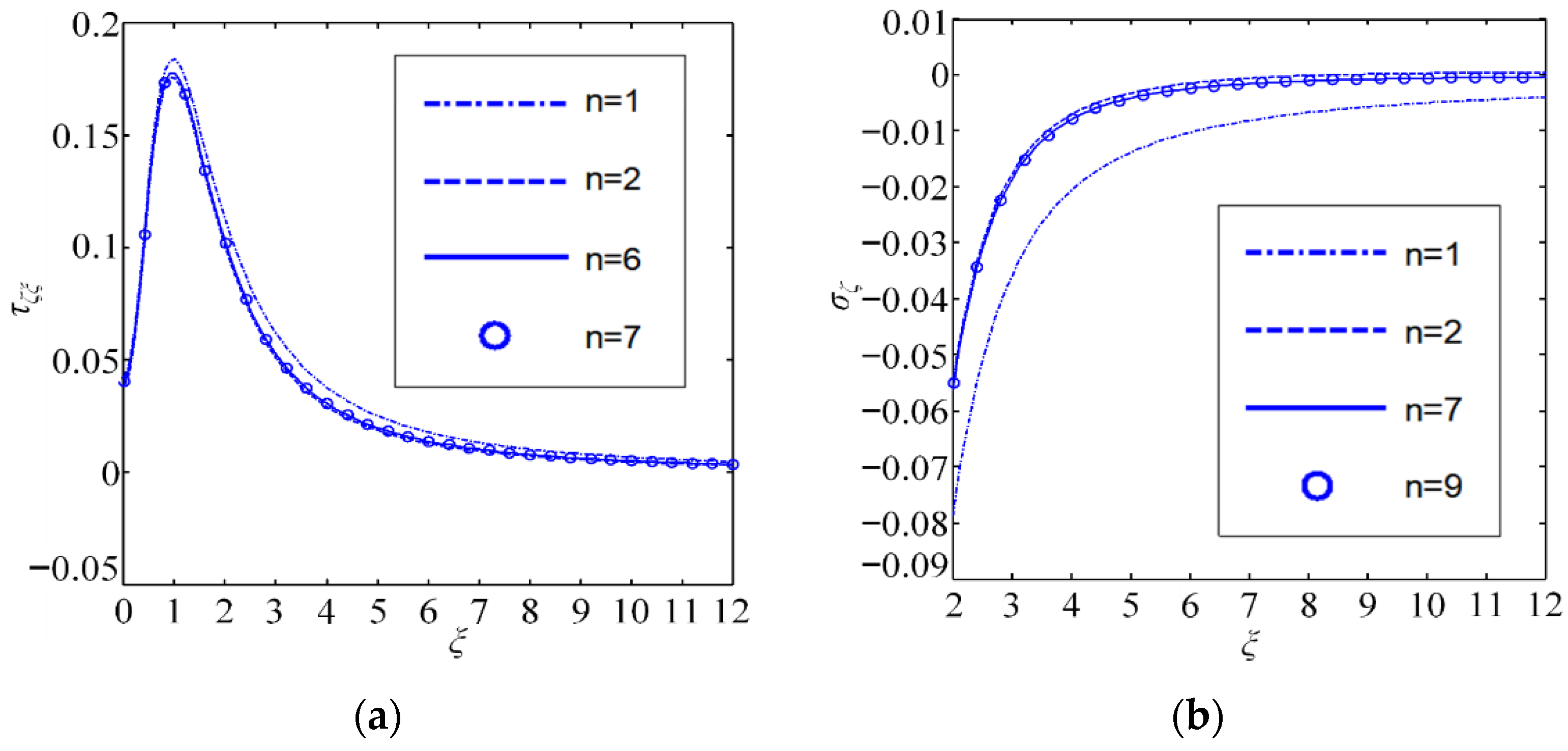
The Scarborough criterion ε a < ε s is used to estimate the solution accuracy, where ε a is the relative percentage error and ε s = 0.5 × 10 2     m % is the tolerance, ensuring the correctness of at least the first m significant digits. Since the coating/substrate system consists of PZT-5 and zinc oxide, profiles of τ ξ ζ and σ ζ along the interface   z = 0 for different iterations n are plotted in Figure 2.

4.2. Impact Induced by Coating Thickness Against Maximal Interfacial Stresses as Well as Electric Displacement

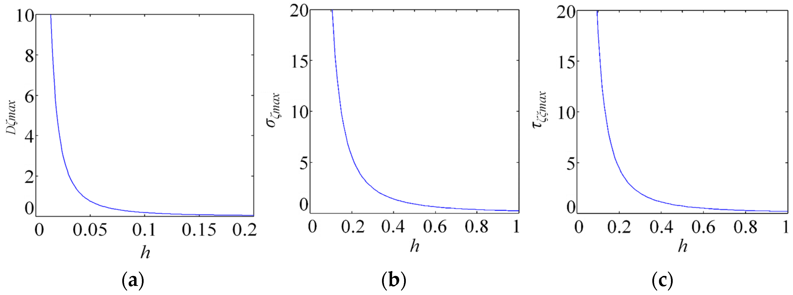
Curves showing the effect of coating thickness on the maximum interfacial stresses τ ζ ξ m a x and σ ζ m a x and the maximum interfacial electric displacement D ζ m a x are plotted in Figure 3 to demonstrate the proposed quantitative method.
From Figure 3, we can see that the maximum interfacial electric displacement D ζ m a x , normal stress σ ζ m a x , and shear stress τ ζ ξ m a x are strongly dependent on the coating thickness H . Importantly, a larger H leads to more pronounced changes in the electro-elastic field. For H < 0.03 , a steeper variation of D ζ m a x is observed in Figure 3a; a slight reduction in thickness causes a substantial increase in electric displacement. When H < 0.2 , both coating tensile failure and interfacial debonding must be considered to ensure the reliable design of piezoelectric energy harvesters. This trend can be exploited to enhance harvester performance under optimal conditions.
Using the three thickness parameters H , h , and h 0 defined in Equation (50), the influence of coating thickness on the electro-elastic field can be examined without increasing the computational cost. Comparisons for two different actual thicknesses, h 1 and h 2 , are given below.
First, at actual thickness h 1 , set h 0 = h 1 and P z 1 = c 33 h 1 2 ; then, H = h 1 / h 0 = 1 and all non-dimensional electro-elastic components E E 1 are obtained.
Second, at actual thickness h 2 , set h 0 = h 2 and P z 2 = c 33 h 2 2 ; then, H = h 2 / h 0 = 1 and the non-dimensional components are identical to those of E E 1 .
When studying how thickness affects the field, all factors other than thickness (e.g., external force) are kept the same. Changing the thickness from h 1 to h 2 simply changes the point force from P z 1 = c 33 h 1 2 to P z 2 = c 33 h 2 2 , and vice versa. The associated non-dimensional components E E 1 for P z 1 = c 33 h 1 2 are determined below:
E E 2 = E E 1 × h 1 2 h 2 2

4.3. Stress Component and Electric Displacement Contours with the Tangential Line Force

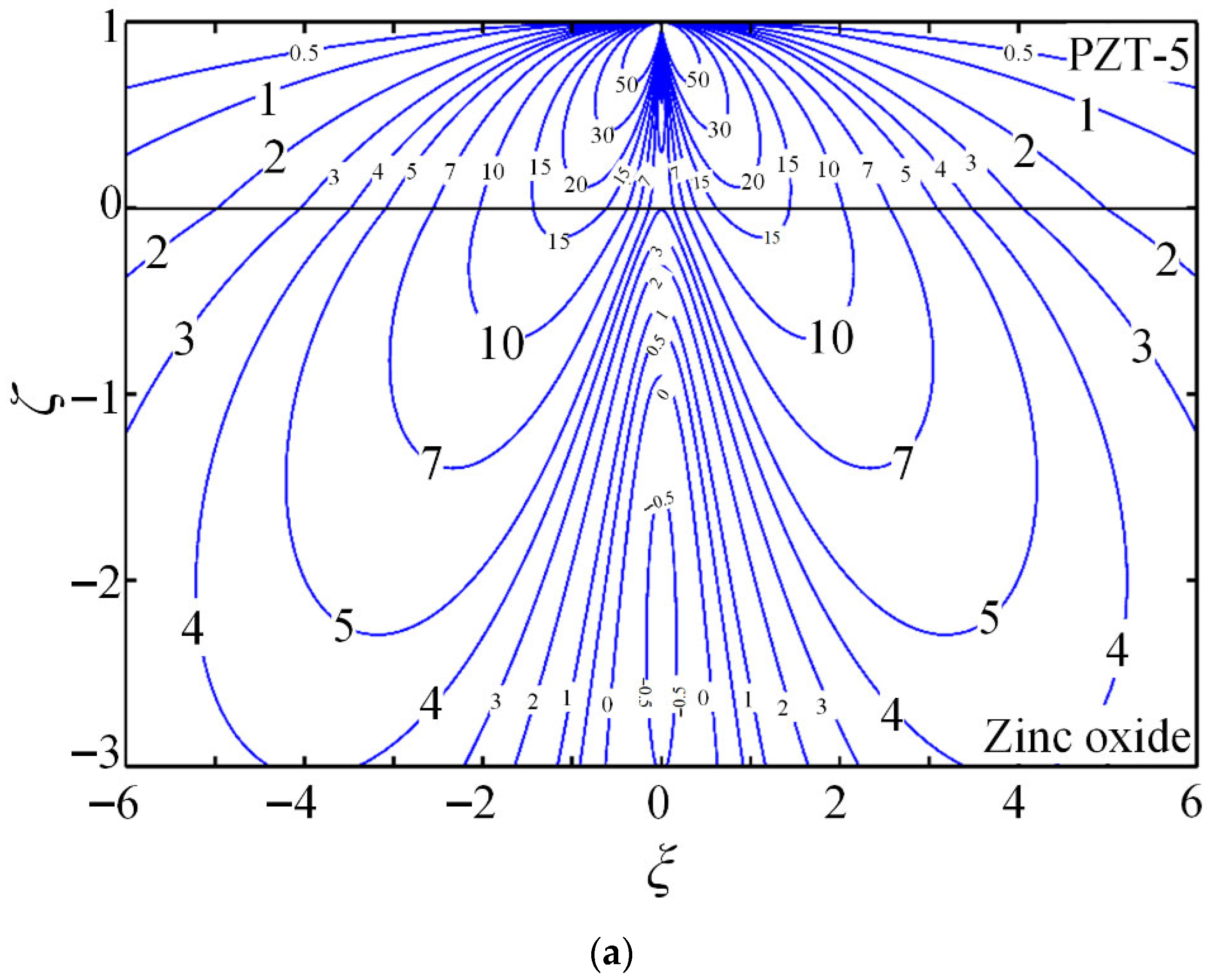
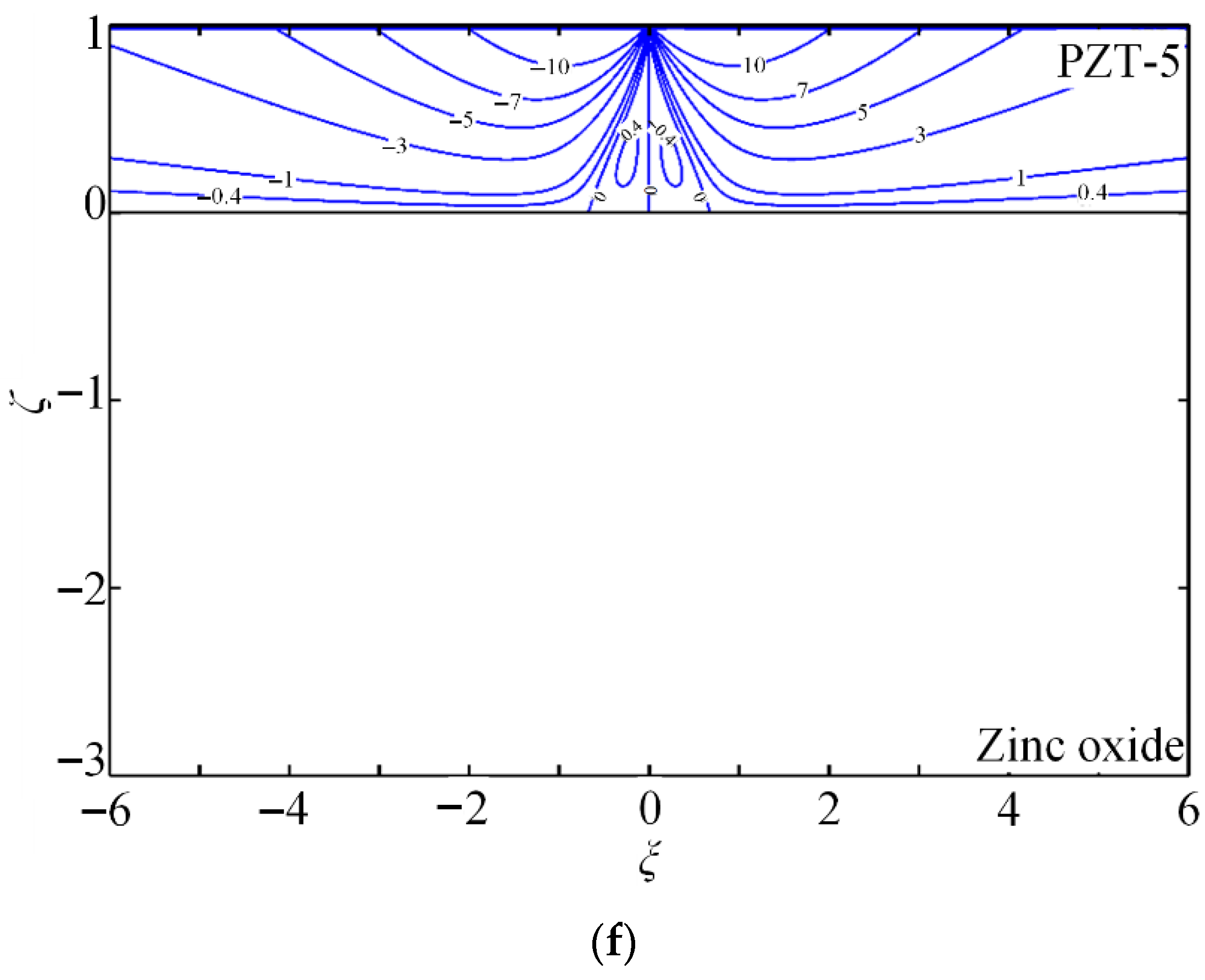
The contours of the non-dimensional Green stress components τ ζ ξ × 10 2 , σ ξ × 10 2 , and σ ζ × 10 2 , electric displacements D ξ × 10 2 and D ζ × 10 2 , and electric potential ϕ × 10 2 are presented to demonstrate the quantitative capability of the proposed method. PZT-5 is used as the coating, while zinc oxide (dielectric) or hexagonal zinc (electrical conductor) serves as the substrate. Figure 4 shows the coupled-field component contours for piezoelectric energy harvesters composed of PZT-5 piezoelectric ceramic coating and zinc oxide substrate (dielectric) under a tangential line force.
Case 1. PZT-5/zinc oxide system subjected to tangential line force P x .
(1)
For a piezoelectric coupling field, the distribution can be quite complicated, especially within the coating. Owing to the piezoelectric coupling effect, large gradients and high field values are obtained; these features must be considered for the reliable design of piezoelectric energy harvesters under optimal conditions. Numerical approaches such as FEM require extremely fine meshes to simulate the coupled fields, often leading to ill-conditioned systems and inaccurate results. Consequently, it becomes difficult to obtain accurate and stable solutions for piezoelectric coating structures with conventional numerical platforms.
(2)
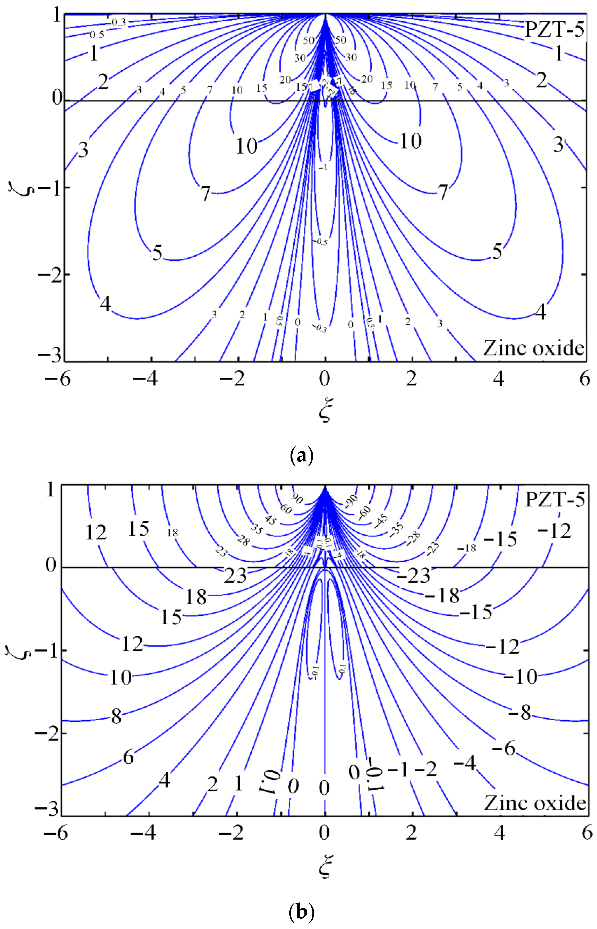
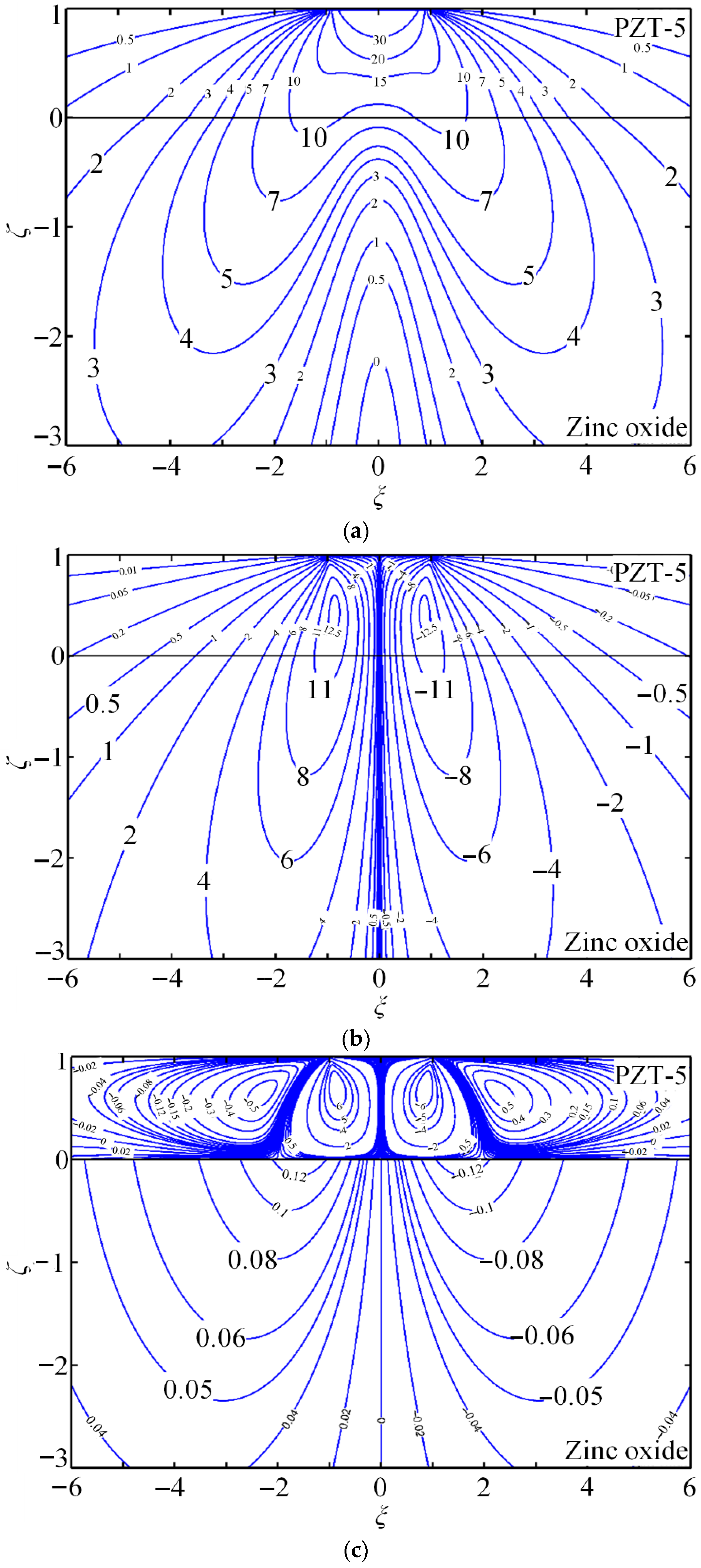
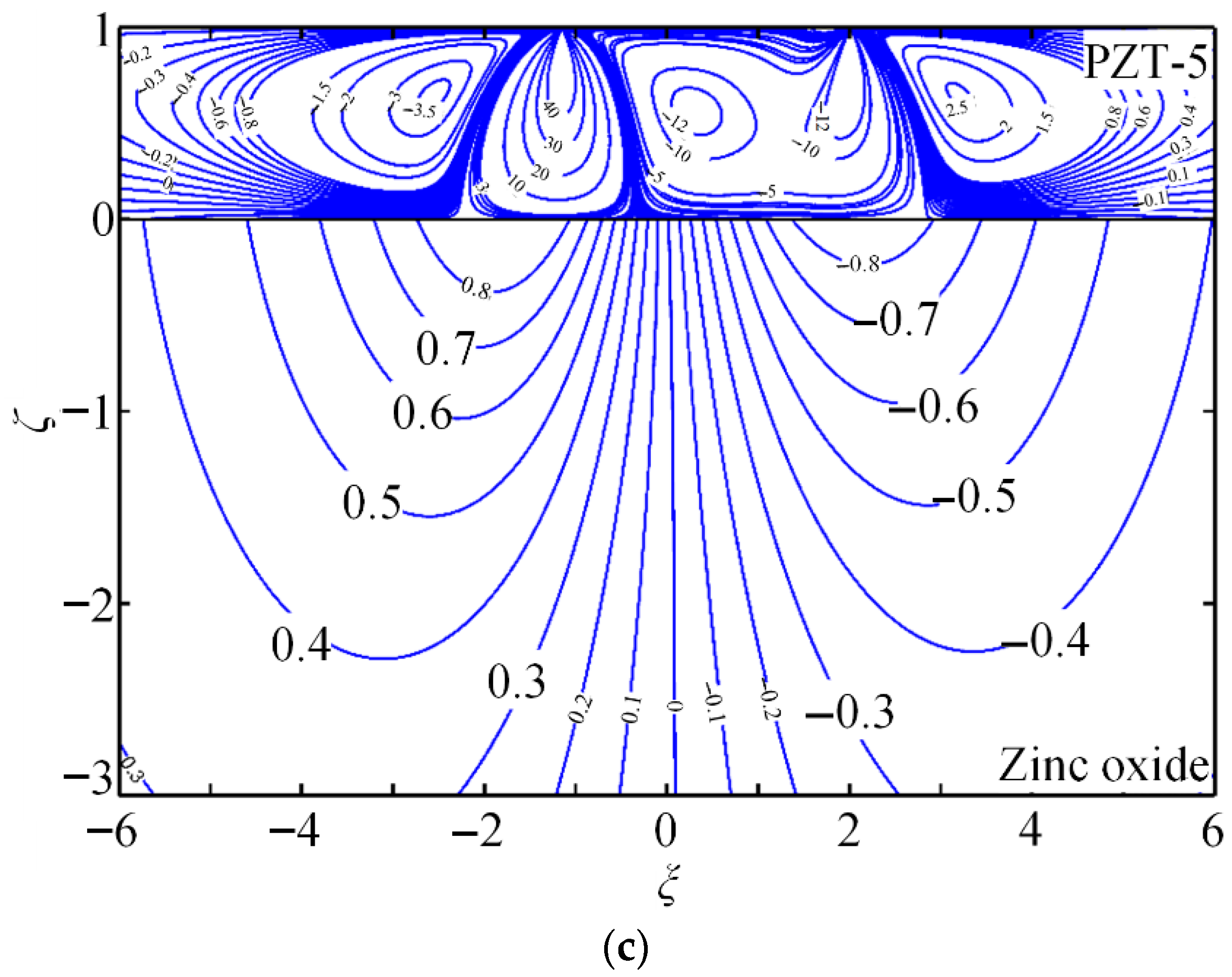
Shear stresses τ ξ ζ are shown in Figure 4a and Figure 5a, normal stresses σ ζ are shown in Figure 4c and Figure 5c, electrical displacements D ζ are shown in Figure 4e, and potentials ϕ are shown in Figure 4f, which show interfacial continuity, conforming to interfacial continuity Equation (20). However, the gradient of the above components shows interfacial discontinuity; as a result, contours are angled during interface crossing. This can be attributed to interfacial effect resulting from various coating–substrate material characteristics, which can be even apparent within contours for electrical displacements D ζ . Normal stresses σ ξ from Figure 4b and Figure 5b and electrical displacements D ξ from Figure 4d are identical owing to interfacial discontinuity. In addition, a hexagonal zinc substrate serves as the electrical conductor with interfacial distribution of free charge because of the polarization effect. This substrate is the equipotential body ( ϕ from Figure 5f) without electric displacement components ( D ξ from Figure 5d, D ζ from Figure 5e).
Case 2. PZT-5/Hexagonal zinc system under tangential line force P x .
The reliability and performance of piezoelectric energy harvesters are governed by the internal stress field. The stress contours in Figure 4a–c and Figure 5a–c are therefore employed to design harvesters with enhanced safety and stability.
(1)
Stress contours reveal substantially larger stress components within the coating than in the substrate. When a tangential line force is applied, most of the mechanical energy is confined to the coating, enhancing its electromechanical response.
(2)
A steep stress gradient appears around the zero-stress contour; as the stress field varies, energy release can interact with micro-cracks, potentially driving crack propagation and eventual device failure.
(3)
Figure 4a–c and Figure 5a–c are the dielectrics of the substrate. The stress component profiles in Figure 4a–c and Figure 5a–c are very complicated, without any universal rules to follow. It can be ascribed to the coupling effect induced by the piezoelectric coupling field. When designing piezoelectric energy harvesters, it is necessary to conduct comprehensive analysis and optimization based on precise computation.
(4)
Positive interfacial normal stress σ ζ and shear stress τ ξ ζ can initiate tension and shear delamination, leading to failure. Figure 4a shows that τ ξ ζ is positive under the tangential line force; Figure 4c and Figure 5c indicate that the peak σ ζ occurs near the loading point. Similarly, Figure 5b shows positive interfacial shear stress with its maximum close to the origin.
(5)
Normal stresses σ ξ (Figure 4b and Figure 5b) exhibit interfacial discontinuity; the interface effect induces opposite stress states on opposite sides of the interface.
Typically, these opposite stress states can initiate interfacial cracks, and subsequent crack growth and accumulation may lead to interfacial delamination. Consequently, such dangerous stress states must be minimized or eliminated when designing piezoelectric energy harvesters.
Piezoelectric energy harvesters operate by outputting an electric field that converts mechanical energy into electrical energy. Their efficiency is determined by the amount of electric field energy generated. Figure 4e,f and Figure 5e,f show contours of the electric field components. Piezoelectric energy harvesters are prepared through placing an output electrode at the position with the highest electric field.
(1)
For each electric displacement component and the potential, peak values occur on the upper surface at the midpoint (Figure 4d–f and Figure 5d–f).
(2)
Three peak values of electric displacement D ξ appear at the interface midpoint and on both sides along the ζ -coordinate (Figure 4d and Figure 5d): a negative value at the midpoint and positive values on the two sides. Two opposite peak values of D ζ occur at the interface on both ζ sides (Figure 4e and Figure 5e). For the dielectric substrate, Figure 5a shows two negative interfacial peaks of potential ϕ on both sides; for the electrically conducting substrate, Figure 5f shows that the interfacial potential ϕ is zero throughout.
(3)
When electrodes are technologically embedded beneath the piezoelectric coating or substrate at any arbitrary position, higher-performance piezoelectric energy harvesters can be fabricated. Based on the electric field contours in Figure 4d and Figure 5d, the optimal pre-embedded electrode location is determined.
(4)
Performance is assessed by comparing multi-point output measurements of several electric field peak values. Subsequently, piezoelectric energy harvesters with superior efficacy are realized through the synergistic use of multi-point electric field energy.

4.4. Stress Component and Electric Displacement Contours in the Arbitrary Distributed Force

Notably, in real applications, the applied forces are not necessarily line forces but complicated distributed loads. Analytical or numerical integration, together with the superposition principle, can be used to obtain accurate coupled-field solutions in piezoelectric energy harvesters under arbitrary loading. Figure 6 shows the contours of the piezoelectric coupled field under a uniformly distributed force (Equation (51)) obtained by Gaussian numerical integration. Figure 7 shows contours under a semi-elliptical distributed force (Equation (52)), and Figure 8 shows contours under an arbitrary distributed force (Equation (53)). Under line loads, each coupled-field component is singular, whereas under distributed loads, they are non-singular and satisfy the surface boundary conditions when the superposition principle is utilized.
Case 3. PZT-5/zinc oxide system under a uniform distributed force.
Case 4. PZT-5/zinc oxide system under an elliptical distributed force.
Case 5. PZT-5/zinc oxide system under an arbitrary distributed force.

5. Conclusions

Two-dimensional Green functions are obtained to analyze the mechanical response of orthotropic piezoelectric coatings under tangential surface line forces. The main conclusions are as follows:
(1)
Harmonic functions (four sets) in the form of elementary functions are formulated, enabling the determination of the electromechanical coupling fields in piezoelectric energy harvesters. An orthotropic piezoelectric layer is combined with an orthotropic elastic substrate through a systematic permutation of material constants within a general solution framework.
(2)
By combining linear superposition theory with Gaussian quadrature, the coupled fields can be efficiently computed. Numerical studies shed important light on device behavior: coating fracture and interfacial delamination are the predominant failure modes that must be prioritized in reliability assessments. To optimize performance, energy conversion efficiency can be enhanced by adjusting the material and structural parameters.

Author Contributions

J.T.: Writing—original draft, Investigation, Formal analysis, Data curation. Y.Z.: Writing—review and editing, Writing—original draft, Resources, Investigation, Formal analysis, Data curation. P.-F.H.: Supervision, Methodology, Investigation. Funding acquisition, Conceptualization. All authors have read and agreed to the published version of the manuscript.

Funding

The current work was supported by the Department of Education of Guangdong Province of China (Grant Nos. 2023KCXTD062, 2023ZDZX3065, and 2021GCZX018).

Data Availability Statement

The original contributions in this work have been included in this manuscript; further enquiries should be directed to the corresponding author.

Conflicts of Interest

Author Yang Zhang was employed by the company Beijing Xinghang Mechanical-Electric Equipment Co., Ltd. The remaining authors declare that the research was conducted in the absence of any commercial or financial relationships that could be construed as a potential conflict of interest.

References

  1. Sun, W.; Thompson, D.J.; Yurchenko, D. Energy harvesting technologies on high-speed railway infrastructure: Review and comparative analysis of the potential and practicality. Sustain. Energy Technol. Assess. 2025, 74, 104187. [Google Scholar] [CrossRef]
  2. Bhatt, K.; Kumar, S.; Kumar, S. A review on energy harvesting technologies: Comparison between non-conventional and conceptual approaches. Energy Rep. 2024, 12, 4717–4740. [Google Scholar] [CrossRef]
  3. Jiao, W.; Ma, R.; Gao, Y. Research advances in electrochemical human motion energy harvesting technologies. J. Electroanal. Chem. 2024, 967, 118474. [Google Scholar] [CrossRef]
  4. Cao, D.; Qin, W.; Zhou, Z. Enhancing wind energy harvesting through two V-shaped attachments and monostable characteristics in the galloping piezoelectric harvester. Energy Convers. Manag. 2024, 318, 118871. [Google Scholar] [CrossRef]
  5. Zhou, Z.; Cao, D.; Huang, H.; Qin, W. Biomimetic swallowtail V-shaped attachments for enhanced low-speed wind energy harvesting by a galloping piezoelectric energy harvester. Energy 2024, 304, 132063. [Google Scholar] [CrossRef]
  6. Cook-Chennault, K.A.; Thambi, N.; Sastry, A.M. Powering MEMS portable devices—A review of non-regenerative and regenerative power supply systems with special emphasis on piezoelectric energy harvesting systems. Smart Mater. Struct. 2008, 17, 043001. [Google Scholar] [CrossRef]
  7. Verma, A.K.; Rahman, M.A.; Vashishtha, P.; Guo, X.Y.; Sehrawat, M.; Mitra, R.; Giridhar, S.P.; Waqar, M.; Bhoriya, A.; Murdoch, B.J.; et al. Oxygen-Passivated Sulfur Vacancies in Monolayer MoS2 for Enhanced Piezoelectricity. ACS Nano 2025, 19, 3478–3489. [Google Scholar] [CrossRef]
  8. Dai, K.; Huo, Z.Y.; Miao, X.Y. Self-powered triboelectric functional devices and microsystems in health-care applications: An energy perspective. EnergyChem 2023, 5, 100109. [Google Scholar] [CrossRef]
  9. Chen, W.; Mo, J.; Zhao, J.; Ouyang, H. A two-degree-of-freedom pendulum-based piezoelectric-triboelectric hybrid energy harvester with vibro-impact and bistable mechanism. Energy 2024, 304, 132143. [Google Scholar] [CrossRef]
  10. Wang, J.; Kan, J.W.; Gu, Y.Q.; He, C.Y. Design, performance evaluation and calibration of an indirectly-excited piezoelectric wind energy harvester via a double-bluffbody exciter. Energy Convers. Manag. 2023, 284, 116969. [Google Scholar] [CrossRef]
  11. Kan, J.W.; Wu, Y.Q.; Li, S.J.; Wang, S.Y. A tunable rotational energy harvester exploiting a flexible-clamping piezoelectric beam by deploying magnetic repulsive force. Sens. Actuators A Phys. 2023, 353, 114198. [Google Scholar] [CrossRef]
  12. Wong, V.K.; Ho, J.H.; Chai, A.B. Performance of a piezoelectric energy harvester in actual rain. Energy 2017, 124, 364–371. [Google Scholar] [CrossRef]
  13. Wang, W.; Cao, J.; Bowen, C.R.; Zhou, S. Optimum resistance analysis and experimental verification of nonlinear piezoelectric energy harvesting from human motions. Energy 2017, 118, 221–230. [Google Scholar] [CrossRef]
  14. Huang, H.H.; Chen, K.S. Design, analysis, and experimental studies of a novel PVDF-based piezoelectric energy harvester with beating mechanisms. Sens. Actuators A Phys. 2016, 238, 317–328. [Google Scholar] [CrossRef]
  15. Wang, H.; Yi, M.; Zhang, Z.; Zhang, H. A wind-solar energy harvester based on airflow enhancement mechanism for rail-side devices. Energy 2023, 283, 129116. [Google Scholar] [CrossRef]
  16. Poulin-Vittrant, G.; Oshman, C.; Opoku, C.; Dahiya, A.S. Fabrication and characterization of ZnO nanowire-based piezoelectric nanogenerators for low frequency mechanical energy harvesting. Phys. Procedia 2015, 70, 909–913. [Google Scholar] [CrossRef]
  17. Zhao, F.; Wang, Z.; Bai, H.; Tang, H. Energy harvesting based on flow-induced vibration of a wavy cylinder coupled with tuned mass damper. Energy 2023, 282, 128584. [Google Scholar] [CrossRef]
  18. Guo, Y.; Maalla, A.; Habibi, M.; Moradi, Z. Electroelastic wave dispersion in the rotary piezoelectric NEMS sensors/actuators via nonlocal strain gradient theory. Mech. Syst. Signal Process. 2024, 216, 111453. [Google Scholar] [CrossRef]
  19. Fan, K.; Tan, Q.; Liu, H.; Cai, M. Harvesting energy from twisting vibration of a rotor suspended by a piece of string. Smart Mater. Struct. 2019, 28, 07LT01. [Google Scholar] [CrossRef]
  20. Lin, S.; Kan, J.; He, C.; Yu, Y. A direction-parallel piezoelectric wind-induced vibration energy harvester with the transducer movement oriented toward wind direction for pipeline energy harvesting. Energy 2025, 319, 135028. [Google Scholar] [CrossRef]
  21. Zhang, P.; Lin, W.; Xie, Z.; Cao, H. L-shaped cantilever beam piezoelectric energy harvester with frequency up-conversion for ultra-low-frequency rotating environments. Mech. Syst. Signal Process. 2025, 225, 112281. [Google Scholar] [CrossRef]
  22. Bagherzadeh, R.; Abrishami, S.; Shirali, A.; Rajabzadeh, A.R. Wearable and flexible electrodes in nanogenerators for energy harvesting, tactile sensors, and electronic textiles: Novel materi-als, recent advances, and future perspectives. Mater. Today Sustain. 2022, 20, 100233. [Google Scholar] [CrossRef]
  23. Zhang, X.F.; Di, H.S.; Tzou, H.S. Experimental study of a piezoelectric ring energy harvester. In Proceedings of the Symposium on Piezoelectricity, Acoustic Waves, and Device Applications (SPAWDA), Changsha, China, 25–27 October 2013; Zhejiang University Press: Hangzhou, China, 2013; pp. 26–32. [Google Scholar]
  24. Farhan, M.; Muthalif, A.G.A.; Ali, M.S.M. Innovative approaches to optimize vibration energy harvesting (VEH): A comprehensive review. Energy Rep. 2024, 12, 5194–5219. [Google Scholar] [CrossRef]
  25. Zhang, C.; Jiang, Z.; Sun, M. Nature-inspired helical piezoelectric hydrogels for energy harvesting and self-powered human-machine interfaces. Nano Energy 2025, 136, 110755. [Google Scholar] [CrossRef]
  26. Rasheed, A.; Ajmal, S.; Wang, P.; Lee, S.G. Energizing the future: Unveiling challenges and prospects in MXene-based piezoelectric and triboelectric nanogenerators for micro-and nanoscale energy harvesting applications. Appl. Mater. Today 2024, 39, 102270. [Google Scholar] [CrossRef]
  27. Huang, S.Q.; Tang, P.J.; Hou, P.F.; Zhang, W.H. A method of coating analysis based on cylindrical indenter loading on coated structure. Acta Mech. 2023, 234, 2223–2267. [Google Scholar] [CrossRef]
  28. Li, Y.; Tang, S.; Li, P.; Ren, J. Shear mode solutions to penny-shaped crack problems in two-dimensional hexagonal piezoelectric quasicrystal media. Theor. Appl. Fract. Mech. 2024, 134, 104762. [Google Scholar] [CrossRef]
  29. Huang, R.; Ding, S.; Chen, Q.; Lv, C.; Zhang, X. Sliding frictional contact of one dimensional hexagonal piezoelectric quasicrystals coating on piezoelectric substrate with imperfect interface. Int. J. Solids Struct. 2022, 239–240, 111423. [Google Scholar] [CrossRef]
  30. Wang, Z.; Ma, K.; Xie, Y.; Long, G.; Zeng, X. Finite element analysis on properties evolution of slab track FLC under the coupling action of rainfall and fatigue load. Eng. Struct. 2022, 271, 114919. [Google Scholar] [CrossRef]
  31. Biswas, S.; Schwen, D.; Hales, J.D. Development of a finite element based strain periodicity implementation method. Finite. Elem. Anal. Des. 2020, 179, 103436. [Google Scholar] [CrossRef]
  32. Marchiori, G.; Lopomo, N.; Boi, M.; Berni, M.; Bianchi, M.; Gambardella, A. Optimizing thickness of ceramic coatings on plastic components for orthopedic applications: A finite element analysis. Mater. Sci. Eng. C 2016, 58, 381–388. [Google Scholar] [CrossRef]
  33. Moradi, A.; Ansari, R.; Hassanzadeh-Aghdam, M.K.; Jang, S.H. Thermomechanical behavior of carbon nanotube/graphene nanoplatelet-reinforced shape memory polymer nanocomposites: A micromechanics-based finite element approach. Eur. J. Mech. A Solids 2024, 107, 105360. [Google Scholar] [CrossRef]
  34. Tang, X.; Yang, W.; Yang, Q.; Liang, Y. Effects of interfacial imperfections on nanoscale adhesive contact for layered medium. Appl. Math. Model. 2025, 138, 115803. [Google Scholar] [CrossRef]
  35. Zhang, X.C.; Xu, B.S.; Wang, H.D.; Jiang, Y.; Wu, Y.X. Application of functionally graded interlayer on reducing the residual stress discontinuities at interfaces within a plasma-sprayed thermal barrier coating. Surf. Coat. Technol. 2007, 201, 5716–5719. [Google Scholar] [CrossRef]
  36. Shang, S.; Xiao, J.; Jiang, T.; Zhang, W.H. Analytical solution of multilayered structures with Green’s function. Int. J. Solids Struct. 2024, 290, 112636. [Google Scholar] [CrossRef]
  37. Li, Q.; Hou, P.F.; Shang, S.; Zhang, W. Thermal-stress assessment of double-layer thermoelastic coatings based on Green’s function. Int. J. Solids Struct. 2023, 260–261, 112041. [Google Scholar] [CrossRef]
  38. Tong, J.; Xu, Z.L.; Li, J.P.; Zhang, Y.; Hou, P.F. Green’s function for a line heat source acting on the surface of a coated isotropic thermoelastic material. J. Therm. Stresses. 2019, 42, 279–293. [Google Scholar] [CrossRef]
  39. Hou, P.F.; Zhang, Y. Study on the piezoelectric coated devices based on the 2D Green’s functions under a tangential line force. Z. Angew. Math. Phys. 2018, 69, 48. [Google Scholar] [CrossRef]
  40. Tong, J.; Li, J.; Su, J.; Liu, Y.J. Two-dimensional Green’s function for an isotropic equal-thickness double-layer structure. AIP Adv. 2025, 15, 015138. [Google Scholar] [CrossRef]
  41. Ding, H.J.; Wang, G.Q.; Chen, W.Q. A boundary integral formulation and 2D fundamental solutions for piezoelectric media. Comput. Methods Appl. Mech. Eng. 1998, 158, 65–80. [Google Scholar] [CrossRef]
  42. Hou, P.F.; Jiang, H.Y.; Li, J.R. A method for the orthotropic coating-substrate system: Green’s function for a normal line force on the surface. Int. J. Mech. Sci. 2015, 96–97, 172–181. [Google Scholar] [CrossRef]
Figure 1. The tangential line force P x on the orthotropic-coated structure surface.
Energies 18 05564 g001
Figure 2. (a,b) Non-dimensional Green stresses at interfaces z = 0 and τ m n ( τ ζ ξ and σ ζ ).
Energies 18 05564 g002
Figure 3. (ac) Impacts of non-dimensional coating thickness H on maximal interfacial electric displacement D ζ m a x , maximal interfacial normal stress σ ζ m a x , and maximal interfacial shear stress τ ζ ξ m a x .
Energies 18 05564 g003
Figure 4. (af) Contours for non-dimensional Green stresses τ ζ ξ × 10 2 and σ ζ × 10 2 , σ ξ × 10 2 , and σ ζ × 10 2 ; non-dimensional Green electric displacements D ξ × 10 2 and D ζ × 10 2 ; and non-dimensional Green potential ϕ × 10 2 .
Energies 18 05564 g004aEnergies 18 05564 g004bEnergies 18 05564 g004c
Figure 5. (af) Contours for non-dimensional Green stresses τ ζ ξ × 10 2 , σ ξ × 10 2 , and σ ζ × 10 2 ; non-dimensional Green electric displacements D ξ × 10 2 and D ζ × 10 2 ; and non-dimensional Green potential ϕ × 10 2 .
Energies 18 05564 g005aEnergies 18 05564 g005bEnergies 18 05564 g005c
Figure 6. (ac) Contours for non-dimensional Green stresses τ ζ ξ × 10 2 and σ ζ × 10 2 and non-dimensional Green electric displacement D ζ × 10 2 .
Energies 18 05564 g006aEnergies 18 05564 g006b
Figure 7. (ac) Contours for non-dimensional Green stresses τ ζ ξ × 10 2 and σ ζ × 10 2 and non-dimensional Green electric displacement D ζ × 10 2 .
Energies 18 05564 g007
Figure 8. (ac) Contours for non-dimensional Green stresses τ ζ ξ × 10 2 and σ ζ × 10 2 and non-dimensional Green electric displacement D ζ × 10 2 .
Energies 18 05564 g008aEnergies 18 05564 g008b
Table 1. Orthotropic piezoelectric and elastic material properties [42].
MaterialZinc OxideHexagonal ZincPZT-5H
Elastic constants
(×109 N/m)
C11209.7162.8126
C13105.136.253
C33210.962.7117
C4442.538.535.3
Piezoelectric constant
(C/m2)
e31//−6.5
e33//13
e15//17
Dielectric constant
(×10−9 C/Vm)
ε110.17/15.1
ε330.25/13
Disclaimer/Publisher’s Note: The statements, opinions and data contained in all publications are solely those of the individual author(s) and contributor(s) and not of MDPI and/or the editor(s). MDPI and/or the editor(s) disclaim responsibility for any injury to people or property resulting from any ideas, methods, instructions or products referred to in the content.