Abstract
This paper presents a strategy to mitigate electromagnetic noise in induction motors for electric vehicles by optimizing the rotor slot count and skewing distance. Initially, the magnetomotive forces (MMF) of the stator and rotor windings, air-gap permeance, and the predominant radial electromagnetic force waves in the air-gap magnetic field were analytically determined and compiled. A finite element model of the original 36/42 straight-slot configuration was established for simulation validation. Subsequently, a preliminary optimization scheme for rotor slot number was proposed. A systematic analysis was conducted of the circumferential distribution of radial force waves and their harmonic components in both temporal and spatial orders by comparing electromagnetic vibration characteristics across different rotor slot configurations (42 versus 53 slots) using two-dimensional Fourier decomposition. Furthermore, building upon the mechanism of tooth harmonic suppression via rotor skewing, an advanced optimization strategy for skewing distance was developed. Comparative analysis of harmonic content in air-gap flux density under three configurations (straight slot, 1.0× skewing, and 1.2× skewing) revealed the optimal solution. Experimental vibration tests demonstrated significant improvements: the optimized 53-slot rotor with 1.2× skewing reduced vibration amplitudes by 5 dB·Hz at the 2nd-order natural frequency, 5 dB·Hz at the 3rd-order natural frequency, and 18 dB·Hz at the 3rd-order resonance peak compared to the original 42-slot straight-slot design. These results confirm that coordinated optimization of rotor slot number and skewing distance effectively mitigates electromagnetic vibration and noise in traction motors.
1. Introduction
Induction motors are widely used in electric vehicle drive systems due to their simple structure, low cost, high reliability, and wide speed range. However, with the increasing demand for driving comfort, electromagnetic noise generated during motor operation has gradually become one of the key challenges limiting their large-scale application [1]. Electromagnetic noise not only directly affects the acoustic environment inside the vehicle but may also trigger mechanical resonance. Therefore, how to effectively analyze and suppress electromagnetic noise in induction motors has become a key approach to improving the quality of electric vehicles [2,3].
Recently, most research on electromagnetic noise in induction motors has focused on issues such as radial electromagnetic forces in the air gap magnetic field, slot matching, and rotor skew slots. Reference [4] considered the radial electromagnetic forces in a double-slotted rotor induction motor under variable-frequency drive. Based on an in-depth analysis of the air gap magnetic potential, the expression for the air gap magnetic flux density is derived, and 12 types of radial electromagnetic force waves and their corresponding spatiotemporal patterns within the motor’s air gap magnetic field are summarized. Reference [5] provides the mathematical expressions for the radial electromagnetic force waves and their frequencies, generated by the harmonic interaction between the stator and rotor, and conducts a detailed analysis of the composition of the slip frequency sidebands in the current and vibration spectra when the rotor is asymmetric, revealing the vibration components at the power frequency, twice the power frequency, the power frequency harmonics, and twice the slip frequency.
Reference [6] theoretically reveals the influence of the number of rotor slots in a five-phase induction motor on its dynamic response characteristics, establishes a mapping relationship between slot matching parameters and motor vibration and noise, and provides a reference basis for slot number analysis in other phase induction motors. Reference [7] compared the harmonic characteristics of 160 kW and 3000 kW squirrel-cage induction motors under different slot combinations. The results indicated that an increase in the number of rotor slots leads to an increase in the harmonic order of the slots, a reduction in the amplitude of the harmonic field, and a decrease in harmonic-induced losses on the stator and rotor surfaces. Reference [8] took a 36-slot squirrel-cage induction motor as the research object and systematically analyzed the frequency distribution characteristics of electromagnetic force waves corresponding to three different slot matching schemes, revealing the key design criteria for suppressing electromagnetic noise in automotive induction motors: during the motor design stage, a systematic analysis of slot–pole ratio optimization must be conducted.
Reference [9] analyzed the geometric characteristics of two typical rotor topologies—single-sloped slots and double-sloped slots—and described the composition of the air gap fundamental magnetic field and air gap harmonic magnetic fields under the two sloped slot structures, as well as the magnetic field distribution functions of each component. Based on this, an optimized design method for achieving high-efficiency, low-noise induction motors was proposed. Reference [10] conducted electromagnetic vibration research on the Y802-2 cage-type induction motor, proposed an electromagnetic force spatial distribution weighting algorithm based on air-gap magnetic-flux density gradients, and revealed the phase compensation mechanism of skewed slot structures for time–space harmonics, i.e., suppressing tooth harmonics by optimizing the tilt angle of the rotor bars. Reference [11] considered a novel skewed slot design where the rotor is skewed in all four phases. Using two-dimensional Fourier decomposition and three-dimensional finite element methods, the radial electromagnetic force, vibration, and noise were analyzed for different skewed slot configurations. The results showed that compared to single-skewed and double-skewed slots, the novel skewed slot design exhibits better vibration and noise reduction effects. Reference [12] employs a multi-slice method to model the circuit topology of a rotor-slotted cage-type induction motor and conducts a detailed analysis of the spatial harmonics contained in the air gap magnetic flux density waveforms. Currently available studies have concentrated on structural optimization elements, including stator-rotor slot clearance [13], stator–rotor slot skew [14,15], and rotor segmentation [16,17]. Among these, skewed slot technology has been extensively validated to reduce radial electromagnetic force harmonics [18]. However, most of the domestic and international literature focuses solely on either optimizing the number of rotor slots in induction motors or adopting one of the two methods—rotor slot inclination—to reduce electromagnetic noise. After optimizing the number of slots in the rotor of an induction motor, the mechanism by which different oblique slot distances affect electromagnetic noise suppression remains unclear and requires further investigation.
This research investigates a four-pole induction motor designed for electric vehicles, with a stator having 36 slots and a rated power of 10 kW, aiming to reduce its electromagnetic vibration noise. First, the generation mechanism of electromagnetic vibration and noise in induction motors is revealed, and the air gap magnetic field and radial electromagnetic force waves of the motor are analyzed using the magnetic potential and magnetic flux product method. Then, while keeping the number of stator slots constant, a combined analytical and finite element method is used to conduct an in-depth analysis of the radial electromagnetic force waves of motors with different numbers of rotor slots to determine the optimal number of rotor slots. Finally, a two-dimensional Fourier decomposition method is employed to analyze the harmonic composition of the air gap magnetic flux density after tilting the rotor by 1.0 times and 1.2 times the unit stator slot distance, thereby determining the most suitable rotor slot tilt distance for the motor.
2. Theoretical Analysis of Radial Electromagnetic Forces
2.1. Magnetic Potential of Stator and Rotor Windings and Air Gap Magnetic Permeability
The classical electromagnetic wave theory analysis typically takes the magnetic potential of the winding and the magnetic permeability of the air gap as its fundamental points, expressing the magnetic flux density in the air gap as
b(θ, t) = f(θ, t)λ(θ, t),
According to Maxwell’s equations, the radial electromagnetic force wave acting on the stator core is proportional to the square of the magnetic flux density in the air gap, i.e.,
where pr(θ,t) is the radial electromagnetic force wave; b(θ,t) is the air gap magnetic flux density; f(θ,t) is the magnetic potential of the winding; and μ0 is the vacuum magnetic permeability, whose value is 4π × 10−7 H/m.
The magnetic potential synthesized by the stator and rotor windings is analyzed using Fourier analysis, and the results can be expressed as
where F0, Fυ, and Fμ are the fundamental amplitude of the three-phase winding magnetic potential, the υ-th harmonic amplitude of the stator winding magnetic potential, and the μ-th harmonic amplitude of the rotor winding magnetic potential, respectively; p is the number of pole pairs of the motor; θ is the mechanical angle; and φ0, φ1, φ2 are the initial angles of the fundamental wave, the initial angles of the υ-harmonic magnetic flux, and the initial angles of the μ-harmonic magnetic flux, respectively; ω1 is the angular frequency of the composite magnetic flux of the fundamental wave; when the stator has an integer number of slots and the rotor is a squirrel-cage rotor, the angular velocity of the rotor’s μ-harmonic magnetic flux can be expressed as:
Similarly, for the air gap magnetic flux, when the stator and rotor slots are open, the air gap magnetic flux can be approximately expressed as:
where Λ0 is the constant component of the magnetic flux; Λks is the harmonic component of the magnetic flux considering the stator slots; Λkr is the harmonic component of the magnetic flux considering the rotor slots; and Λks and Λkr are the harmonic components of the magnetic flux considering both the stator and rotor slots.
2.2. Magnetic Field in Air Gap and Radial Electromagnetic Force Waves
Generally, the magnetic flux harmonic components Λk1Λk2 are neglected when the stator and rotor are slotted simultaneously, and the air gap magnetic field can be expressed as
In the entire air gap magnetic field of the motor, in addition to the fundamental wave component, there are six main types of harmonics: stator magnetic momentum tooth harmonics, rotor magnetic momentum tooth harmonics, stator magnetic permeability tooth harmonics, rotor magnetic permeability tooth harmonics, winding phase band harmonics, and saturation harmonics. The composition of the fundamental magnetic field and tooth harmonic magnetic fields is shown in Table 1.

Table 1.
The main components of the air gap magnetic field.
In the table, Zs represents the number of stator slots; Zr represents the number of rotor slots; s represents the slip rate; and ks represents the order of the stator tooth harmonic, with values of ±1, ±2, ±3, etc. For example, when ks = ±1, it is referred to as the first-order stator tooth harmonic; kr represents the order of the rotor tooth harmonic, with values the same as ks.
The stator magnetic field tooth harmonic flux density (spatial harmonic magnetic field caused by the non-sinusoidal distribution of the stator windings) and the stator magnetic permeability (periodic variation in the air gap magnetic permeability caused by the stator slot structure) are superimposed vectorially to form the stator-side tooth harmonic magnetic field; similarly, the rotor magnetic field harmonics (harmonic magnetic fields generated by the rotor bars) and the rotor magnetic flux density harmonics (magnetic flux modulation harmonics caused by the rotor slot structure) are vectorially superimposed to form the rotor-side tooth harmonic magnetic field.
Substituting Equation (6) into Equation (2) yields the expression for the radial electromagnetic force wave generated by the air gap magnetic flux density:
As can be seen from Reference [19], the amplitude of electromagnetic force waves decreases in proportion to the n4 order of the force wave. Therefore, three principles apply in the analysis of electromagnetic force waves: the dominance of low-order force waves, the secondary role of high-order force waves, and the ineffectiveness of constant components. Simplifying Equation (7), we obtain the following two main types of radial electromagnetic force waves in air gaps:
- (1)
- Radial electromagnetic force waves generated by the fundamental magnetic field
The radial electromagnetic force waves generated by the fundamental magnetic flux density in the air gap are
The frequency of this component of the force wave is twice the motor power supply frequency, and the order of the electromagnetic force waves is also twice the number of motor pole pairs, making it impossible to eliminate through motor optimization design methods. For large motors with low natural frequencies, low-frequency resonance with twice the power supply frequency is likely to occur, leading to a significant increase in structural vibration amplitude. For medium and small motors with high natural frequencies, the vibration frequency at twice the power supply frequency falls within the low-frequency range that is inaudible to humans, and its impact on practical applications can be neglected.
- (2)
- Radial electromagnetic force waves generated by stator and rotor tooth harmonics
The radial electromagnetic force waves generated by the mutual modulation of stator and rotor tooth harmonics through the air gap magnetic field are:
This component of the force waves is typically the primary contributor to electromagnetic vibration and noise in induction motors, characterized by low order and large amplitude, particularly the first-order tooth harmonics. Suppressing these harmonics is an effective method for reducing electromagnetic vibration and noise.
From Equations (8) and (9), the main magnetic potential waves, magnetic flux waves, and electromagnetic force waves generated by mutual interaction, and their corresponding frequencies in the air gap magnetic field are derived, as shown in Table 2, Table 3, and Table 4, respectively.
Table 2.
The main magnetomotive force wave of the air gap magnetic field.
Table 3.
The main permeability wave of the air gap magnetic field.
Table 4.
The main electromagnetic force waves of the air gap magnetic field.
In the table, υ represents the harmonic order of the stator-side teeth, and μ represents the harmonic order of the rotor-side teeth.
The motor studied in this research has a 36/42 slot configuration. The low-order radial electromagnetic force waves that may exist in this motor are calculated from Table 4 and shown in Table 5:
Table 5.
36/42 slot with electromagnetic wave meter.
Table 5 reveals that the tooth harmonics at (ks = 1, kr = −1) and the stator/rotor winding higher-order harmonics at (k = −4, kr = 1) generate a second-order radial electromagnetic force wave. This low-order force wave readily induces significant electromagnetic vibration and noise in the motor. Given the motor’s maximum speed of 6000 rpm and the number of pole pairs being 2, the maximum frequency of the second-order radial electromagnetic force wave can be calculated as 4600 Hz. This exceeds the second-order natural frequency of small induction motors (typically around 1000 Hz). Furthermore, the second-order electromagnetic force wave includes force waves induced by tooth harmonics, which have a relatively large amplitude. This can easily cause severe resonance in the motor, necessitating optimization of the motor’s slot fit.
3. Finite Element Simulation Verification of Induction Motors for Electric Vehicles
3.1. Establishment of the Simulation Model
A simulation model was established for an induction motor with 36/42 slot pole configurations and a rated power of 10 kW, designed for electric vehicles. The model is shown in Figure 1, and the main parameters are listed in Table 6.
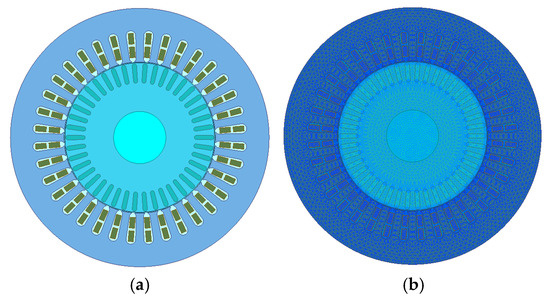
Figure 1.
Two-dimensional finite element model of induction motor for electric vehicle: (a) finite element model; (b) grid partitioning.
Table 6.
Parameters of induction motors for electric vehicles.
In the finite element analysis, the following assumptions are made:
- (1)
- There is an ideal three-phase sinusoidal voltage source supply;
- (2)
- Leakage flux outside the stator core is neglected;
- (3)
- The effects of eddy currents in the stator windings are neglected.
The accuracy of finite element calculation results depends on the quality of the mesh partitioning. Smaller mesh partitions yield higher computational precision, but simultaneously require greater computational resources and longer simulation times. Consequently, it is essential to perform reasonable mesh partitioning for each component of the motor.
This model employs internal motor meshing using the TAU Mesh algorithm. Key meshing parameters include the following: maximum step size for stator and rotor cores: 4 mm; maximum step size for stator windings: 1.5 mm; maximum step size for rotor bars: 1.5 mm; maximum step size for band and internal domains: 1 mm; maximum step size for shaft and external domains: 2.3 mm. The total mesh comprises 24,260 elements, with a single calculation taking approximately 20 with a maximum step size of 1 mm for the band domain and internal domain, and 2.3 mm for the shaft and external domain. The model comprises 24,260 meshes, with a single calculation taking approximately 20 min.
The model employs a magnetic vector position boundary condition set on the outer circumference of the stator core, where the magnetic vector position value is set to zero. This indicates that the magnetic field at the outer boundary of the core is parallel to the boundary.
3.2. Analysis of the Simulation Model
This research employs a 2D finite element model of an induction motor. Figure 2 and Figure 3 show the spatial and temporal distribution of the air gap magnetic flux and electromagnetic force waves of a 10 kW induction motor, respectively.
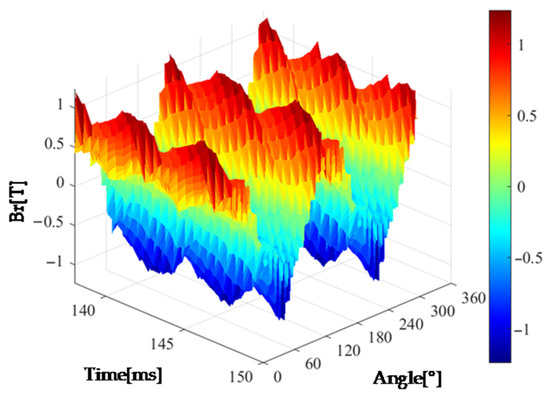
Figure 2.
The spatiotemporal distribution of air gap magnetic flux density.
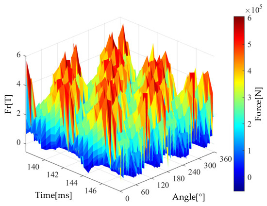
Figure 3.
The spatiotemporal distribution of electromagnetic force waves.
The magnetic flux density and electromagnetic force waves in the air gap exhibit non-uniform distribution in both time (140–160 ms) and spatial angle (0–360°), with significant fluctuations. Such variations may lead to harmonic losses, torque pulsations, and other issues. Further analysis of air gap harmonics is required, along with optimization of slot matching or the adoption of methods such as skewed slots to suppress harmonic components.
4. Optimization of the Number of Slots in the Rotor of an Induction Motor for Electric Vehicles
According to the previously discussed theoretical modeling and simulation verification, the original 36/42 stator–rotor slot configuration used in the electric vehicle induction motor excites low-order radial electromagnetic force waves within the natural frequency range in the air gap. These force waves pose a risk of resonance with the natural frequencies of the motor structural components. As shown in Equation (7), the number of stator slots primarily influences the spatial order distribution of the force waves. As shown in Equations (8) and (9), the number of rotor slots, through the “slot harmonic modulation effect,” simultaneously affects both the spatial order and frequency of the force waves. This coupling effect makes the number of rotor slots the dominant factor in the characteristics of electromagnetic force waves. Adjusting the number of rotor slots can eliminate the superposition conditions of specific-order force waves by altering the phase distribution of rotor conductors without changing the stator winding topology. Furthermore, the cost of adjusting the number of slots is significantly lower than that of stator modifications involving winding reconfiguration.
4.1. Selection of the Optimal Rotor Slot Number
Reference [20] indicates that adopting a wide slot arrangement can reduce the influence of rotor slot openings on the air gap magnetic flux, thereby effectively suppressing air gap harmonic magnetic fields and lowering the electromagnetic vibration and noise levels of the motor.
Based on a rotor with 42 slots, the number of rotor slots was further increased. To distinguish it from the original rotor, the starting point for the analyzed rotor slot number was set to 47 slots. Considering the high motor speed and large output torque, to ensure the mechanical structural strength of the rotor, the maximum number of rotor slots was limited to 54 slots. Therefore, the range of rotor slots to be analyzed is between 47 and 54 slots.
Synchronous additional torque has a significant impact on induction motors used in electric vehicles. It causes a decrease in the electromagnetic torque at the motor’s base speed point and maximum speed point, leading to an increase in stator current and motor losses. Therefore, it must be avoided during motor design. To avoid the generation of large synchronous additional torque, the number of rotor slots must satisfy two constraints: the slot number difference restriction and the slot number combination avoidance constraint [15], specifically defined by Equations (10) and (11).
where k = 1, 2, 3, …, p represents the number of pole pairs in the motor, and m represents the number of phases in the motor. Equation (10) suppresses synchronous additional torque caused by low-order tooth harmonics, while Equation (11) suppresses synchronous additional torque generated by the first-order tooth harmonics of the rotor and the phase harmonics of the stator windings. Therefore, to suppress synchronous additional torque, the rotor slot number Zr ≠ 48, 52.
Radial electromagnetic force wave analysis was conducted on motors with rotor slot numbers Zr = 47, 49, 50, 51, 53, and 54. Since the amplitude values of the higher-order harmonics of the stator windings are relatively low, the radial electromagnetic force waves generated by the higher-order harmonics of the stator windings (8th order and above) were neglected. The analysis results are shown in Table 7.
Table 7.
Radial electromagnetic wave analysis results of different rotor slot number motors.
According to the analysis in Reference [21], the following two conditions can cause motor resonance and generate significant electromagnetic vibration and noise: (1) The order of the force wave must match the order of the motor’s natural modes; (2) The frequency of the force wave must match the motor’s natural frequency.
By performing modal analysis on an induction motor, the modal shapes and corresponding natural frequencies of the motor can be determined. The first-order modal shape of the motor is a unidirectional reciprocating vibration, with a natural frequency above 8000 Hz. Therefore, a first-order force wave will not cause first-order resonance in the motor; the natural frequency of the motor’s second-order vibration mode is around 1000 Hz, so the second-order force wave will cause the motor’s second-order resonance in both mode and frequency, making it the most severe factor affecting the motor’s vibration and noise; the natural frequency of the motor’s third-order vibration mode is around 3800 Hz, so the third-order force wave will also cause the motor’s third-order resonance. Considering that the frequency of the first-order force wave covers the second-order natural frequency of the motor, it will cause the second-order resonance of the motor. The amplitude of electromagnetic force waves decays according to the order n4, and the higher the order of the force wave, the shorter the distance at which it acts on the motor stator, and the better the stator stiffness. Therefore, the third-order force wave causes reduced deformation and noise in the motor.
Combining the characteristics of electromagnetic force wave orders and structural resonance mechanisms, the influence of first-order force waves on motor vibration and noise is smaller than that of second-order force waves and greater than that of third-order force waves. Therefore, from the perspective of radial electromagnetic force waves, the 36/53 slot configuration yields the optimal results.
4.2. Electromagnetic Vibration Analysis of Motors with Different Rotor Slot Numbers
To obtain more accurate analysis results, finite element models were established for the 42-slot rotor and the 53-slot rotor. In the modeling process, the total slot opening width of the rotor was kept constant to better analyze the impact of the number of rotor slots on motor performance. The radial electromagnetic force wave distributions along the air gap circumference for the two motors with 36/42 slot configurations and 36/53 slot configurations are shown in Figure 4a,b.
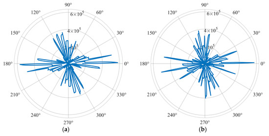
Figure 4.
Distribution of the electromagnetic force wave along air gap: (a) 42-slot radial electromagnetic wave; (b) 53-slot radial electromagnetic force wave.
It can be seen that the electromagnetic force waves generated by the 42 slots in conjunction with the motor extend significantly along the circumference. The radial electromagnetic forces at 1.8°, 11.2°, 181.1°, and 191.2° are 579 kPa, 513 kPa, 569 kPa, and 490 kPa, respectively, all of which are close to 600 kPa. These concentrated, high-amplitude electromagnetic force waves are likely to have a significant impact on the motor structure; the electromagnetic force waves of the 53-slot motor are normally distributed around the circumference, with prominent radial electromagnetic forces at 1.1°, 171°, and 191.2°, measuring 571 kPa, 478 kPa, and 514 kPa, respectively. These electromagnetic force waves, which are uniformly distributed across all angles and have lower amplitudes, exert a more balanced and weaker impact on the motor structure, effectively reducing electromagnetic vibration and noise in the motor.
The radial electromagnetic forces of two motors with 36/42 slot configurations and 36/53 slot configurations were analyzed using two-dimensional Fourier decomposition, and the harmonic content is shown in Figure 5a,b. Analysis reveals that the spatial harmonics of the 4th and 8th orders have relatively high content. This is because the spatial harmonic components of the radial electromagnetic force exhibit characteristics related to the number of poles of the motor; the temporal order is an integer multiple of the electrical frequency. Among the various harmonics, those with both spatial and temporal order of 0 have the most prominent amplitude. These harmonics belong to the DC component of the electromagnetic force and do not cause dynamic excitation of the motor structure. By changing the number of slots in the rotor’s 53 slots, the frequency distribution of the electromagnetic force waves was adjusted, effectively suppressing the second-order electromagnetic force waves that have the greatest impact on motor vibration and noise.
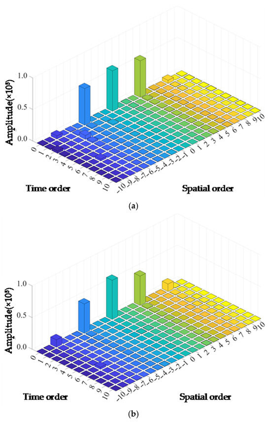
Figure 5.
Temporal and spatial harmonic analysis of radial electromagnetic force: (a) 42-slot radial electromagnetic force harmonic; (b) 53-slot radial electromagnetic force harmonic.
5. Optimization of the Skew Slot Distance for Induction Motors in Electric Vehicles
Rotor skew slots are an effective method for reducing electromagnetic vibration and noise in motors. The skew slot structure induces phase compensation in the spatial harmonics of the air gap magnetic field, resulting in modulation effects that cause changes such as force wave order migration, force wave frequency detuning, and force wave energy redistribution in the spatiotemporal distribution of electromagnetic force waves.
5.1. Weakening Mechanism of Tooth Harmonics by Rotor Slots
The motor slot coefficient is a parameter used to measure the extent of the influence of motor slots on the harmonics of the air gap magnetic field. It reflects the degree to which the time phase difference between the magnetic field and the conductor at different positions, caused by the oblique arrangement of the rotor slots, affects the harmonic electromotive force, magnetic force, and other factors. Mathematically, this value can be obtained by dividing the conductor into segments along the axial direction and using a method similar to that for calculating distribution coefficients. As the number of segments approaches infinity and the phase difference between them approaches 0, the limit is obtained.
Using the derivation principle of the magnetic momentum distribution coefficient, the skew slot coefficient for the υth harmonic can be obtained [9].
where bsk is the skew slot distance, generally equal to one stator slot pitch , and τ is the pole pitch equal to .
Within a certain range, the smaller the skew slot coefficient, the more pronounced the damping effect on tooth harmonics, thereby reducing the electromagnetic vibration and noise of the motor. If the goal is to dampen the υth harmonic, the skew slot coefficient for that harmonic should be approximately 0.
From the preceding text, the stator tooth harmonic υ = kszs + p can be substituted into the skew slot expression to obtain
where p is an integer. For the stator, the first-order tooth harmonic is ks = ±1, and the second-order tooth harmonic is ks = ±2, with the skew slot coefficient approximately equal to zero. The proof process for the rotor end is analogous.
According to Equation (12), the attenuation of different harmonic orders due to the skewed slot distance can be calculated. Considering that an excessively skewed slot distance may cause significant transverse currents, leading to axial forces, increased additional losses, and reduced torque, the skewed slot distance is selected to be 0 to 2 stator tooth pitches for analysis. Analysis of the radial electromagnetic force waves in a 53-slot motor reveals that the winding phase band harmonics associated with the first-order electromagnetic force waves are the 25th harmonics, while those associated with the third-order electromagnetic force waves are the 29th harmonics. Given that the first-order tooth harmonics of the stator (17th and 19th harmonics) have relatively large amplitudes, the first-order tooth harmonics of the stator should also be considered when analyzing the effect of different skew slot distances on the skew slot coefficient. Figure 6 visually depicts the quantitative relationship curves between skew slot distance and the appropriate harmonic skew slot coefficients, illustrating the effect of skew slot distance on various harmonics.
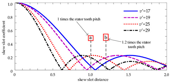
Figure 6.
The corresponding curve of the chute coefficient and the chute distance.
As shown in Figure 6, when the skew slot distance is 1.0 times the stator tooth pitch (marked as point a in the figure), the first-order tooth harmonics of the stator can be effectively attenuated in the air gap magnetic field. However, this position coincides with the peak region of the skew slot coefficients for the 25th and 29th winding phase band harmonics. Therefore, selecting this position results in an unsatisfactory attenuation effect on the first-order radial electromagnetic force waves and third-order radial electromagnetic force waves of the motor. By comparing the skew slot coefficient curves in Figure 6, it is observed that when the skew slot distance is increased to 1.2 times the stator tooth pitch (marked as point b in the figure), although the attenuation effect of the first-order tooth harmonic of the stator is slightly reduced, the suppression effect on the 25th and 29th winding phase harmonic components is significantly enhanced, thereby more effectively reducing the amplitude of low-order radial electromagnetic force waves and the structural resonance risks they induce. Therefore, the rotor skew slot distance for this motor is selected as 1.2 times the stator tooth pitch.
5.2. Simulation Verification of Rotor Skew Slots
The finite element analysis method was used to verify the effectiveness of the motor rotor skew slot design. First, finite element simulation was performed on a motor with a 53-slot rotor and straight slots. Then, the air gap magnetic flux density in the simulation results was analyzed using fast Fourier transform. The analysis results are shown in Figure 7.
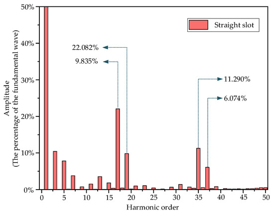
Figure 7.
FFT with air-gap magnetic flux density under the straight slot of a 53-slot rotor.
Analysis of Figure 7 reveals that, in the case of straight slots in the rotor, the harmonic content in the air gap magnetic flux density of the motor is relatively high. Among these, the 17th and 19th harmonics correspond to the first-order tooth harmonics of the stator, i.e., harmonics corresponding to ks = ±1; the 35th and 37th harmonics are winding phase band harmonics that can induce radial electromagnetic force waves, i.e., harmonics corresponding to k = 6.
This research employs a multi-section finite element simulation method, decomposing the skew-slot rotor along the motor axis into multiple cross-sectional bodies. Each cross-sectional body is treated as a straight-slot motor for separate analysis, with the results superimposed to achieve equivalence with the skew-slot configuration. The single-section air gap magnetic flux density and the superimposed oblique slot air gap waveforms obtained from the simulation are shown in Figure 8. It can be observed that after optimizing the design of the rotor skew slots, the harmonic content in the air gap magnetic flux density is significantly reduced, leading to a decrease in the amplitude of radial electromagnetic force waves, thereby reducing motor vibration and noise, consistent with the previous analysis results.
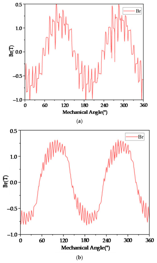
Figure 8.
The air-gap magnetic flux density of straight grooves and inclined grooves: (a) single-section air gap magnetic flux density; (b) magnetic flux density in the synthetic air gap of a rotor with inclined slots.
Simulation analysis was performed on an induction motor with a rotor slot distance of 1.0 times the stator tooth pitch, yielding the air gap magnetic flux. Fourier analysis results are shown in Figure 9.
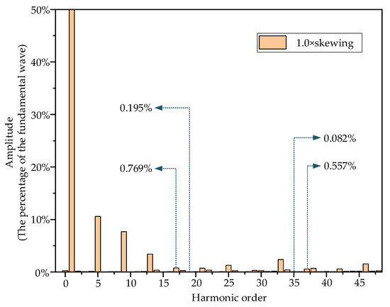
Figure 9.
FFT with a rotor air-gap magnetic density of 1.0 times the chute distance.
Comparing Figure 7 and Figure 9, it can be observed that for this 53-slot motor, when the rotor skewed slot distance is 1.0 times the stator tooth pitch, the first-order tooth harmonics of the stator (17th and 19th harmonics) are significantly suppressed, with their amplitudes reduced to 3.49% and 1.98% of the amplitudes in the case of straight slots. The amplitudes of the winding phase band harmonics (35th and 37th harmonics) that can induce radial electromagnetic force waves are reduced to 0.723% and 9.17% of the original straight slot case, which is beneficial for reducing the electromagnetic vibration and noise of the motor. However, this is not the optimal choice for the motor when the distance between the skewed rotor slots is 1.0 times the stator tooth pitch.
Next, a simulation analysis was conducted on a motor with a rotor skewed slot distance of 1.2 times the stator tooth pitch, and the results were compared with those of a motor with a rotor skewed slot distance of 1.0 times the stator tooth pitch, yielding the air gap magnetic flux. Fourier analysis comparison results are shown in Figure 10. By comparing the results, it can be observed that the motor with a rotor skew slot distance of 1.2 times the stator tooth pitch exhibits similar harmonic suppression effects for specific harmonics (stator first-order tooth harmonics and winding phase band harmonics) as the motor with a rotor skew slot distance of 1.0 times the stator tooth pitch. However, compared to the motor with a rotor skew slot distance of 1.0 times the stator tooth pitch, the motor with a rotor skew slot distance of 1.2 times the stator tooth pitch has the following advantages: the 25th winding phase band harmonic associated with the motor’s first-order radial electromagnetic force wave and the 29th winding phase band harmonic associated with the motor’s third-order radial electromagnetic force wave are both better suppressed; Specifically, the content of the 25th harmonic decreased from 1.269% to 0.617%, and the content of the 29th harmonic decreased from 0.309% to 0.234%, which validates the previous analysis regarding the skew coefficient and skew angle. Based on this, the motor with a skewed slot distance of 1.2 times the stator tooth pitch further reduced the 21st, 22nd, 32nd, and 33rd harmonics. The reduction in these harmonic contents can more effectively prevent motor resonance, reduce electromagnetic vibration, and lower noise. Therefore, for this 53-slot motor, a rotor skewed slot distance of 1.2 times the stator tooth pitch is the optimal choice.
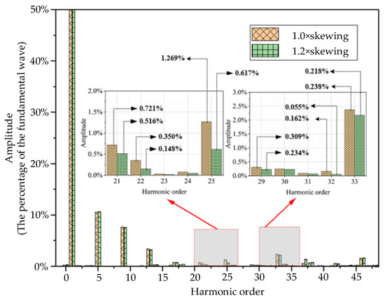
Figure 10.
FFT with different chute distances and rotor air gap magnetic densities.
Rotor skewing not only affects the electromagnetic vibration and noise of induction motors but also impacts performance metrics such as electromagnetic torque and additional losses. Considering the application in electric vehicles, the focus is on electromagnetic performance at the base speed point and maximum speed point. Therefore, further analysis is conducted on the maximum electromagnetic torque and efficiency performance of the motor after rotor slot skewing. Figure 11 shows the maximum electromagnetic torque and efficiency curves across the entire speed range for a 53-slot rotor motor with a skew distance of 1.2 times the stator pitch and a 42-slot straight-slot rotor motor. Comparing the performance of the 53-slot rotor with a skewed slot distance of 1.2 times the stator pitch and the 42-slot straight-slot rotor in Figure 11 reveals that the optimized rotor achieves a 2.8% improvement in electromagnetic torque at the base speed point and a 4.9% enhancement in performance at the maximum speed point compared to the original rotor. The motor’s efficiency remains essentially unchanged across the entire speed range. Consequently, the optimized rotor demonstrates superior electromagnetic torque performance.
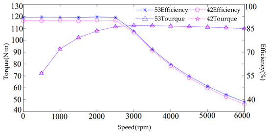
Figure 11.
Torque and efficiency of the 53-slot rotor with 1.2× skewing and the 42-slot straight rotor.
6. Experimental Analysis
To ensure the accuracy and validity of the experiments, this research employed a method of replacing the rotor within the same stator to evaluate the torque performance, efficiency characteristics, and electromagnetic vibration properties of both rotor types. Performance assessments of the two rotors were conducted on a motor drag test bench, as illustrated in Figure 12. The electric vehicle induction motor drag test bench incorporates a torque measuring instrument. Its control console features a power meter and current sensors, enabling measurement of the motor’s torque and efficiency characteristics. Electromagnetic vibration characteristics were measured using an accelerometer sensor mounted on a magnetic base fixed at the center of the motor stator core. Radial electromagnetic forces directly act on the stator, inducing radial electromagnetic vibrations. Since the motor’s shaft coupling acts on the rotor, its influence on radial electromagnetic vibrations can be neglected.
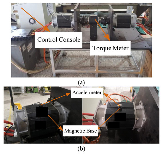
Figure 12.
Performance test with 53-slot rotor with 1.2× skewing and 42-slot straight rotor: (a) motor drag test bench; (b) vibration testing of 42-slot rotors and 53-slot rotors.
Torque and efficiency performance tests were conducted on a 53-slot skewed-slot rotor with 1.2 times the stator pitch and a 42-slot rotor motor on a motor drag test bench. The experimental results are shown in Figure 13. It can be observed that the efficiency of the 53-slot rotor with skewed slots at 1.2 times the stator pitch is essentially consistent with that of the straight-slot 42-slot rotor. However, the base speed torque of the 53-slot rotor is 4.8% higher than that of the 42-slot rotor, and the maximum speed torque is 11.9% higher, demonstrating superior torque performance. This validates the accuracy of the theoretical analysis and simulation tests.
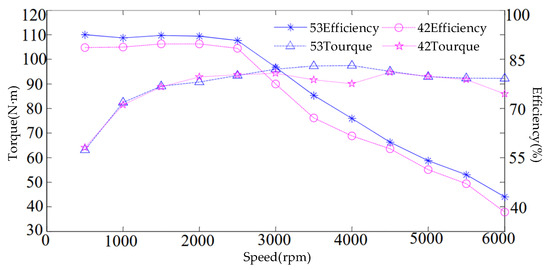
Figure 13.
Measured torque and efficiency of the 53-slot rotor with 1.2× skewing and the 42-slot straight rotor.
Compared with Figure 11, the measured motor torque and efficiency are slightly lower than the simulation results. This discrepancy arises from the combined effects of insufficient machining precision to fully match the design, a higher friction coefficient during actual measurement than in the simulation, and inherent experimental errors. Calculations indicate that the measured values for base speed torque, maximum speed torque, base speed efficiency, and maximum speed efficiency deviate from design values by 7.5%, 6.9%, 4.7%, and 8.8%, respectively. All deviations fall within acceptable tolerance ranges, confirming the validity and feasibility of this 53-slot rotor design.
The electromagnetic vibration and noise of an electric motor are directly related, with vibration amplitude effectively reflecting noise levels and vibration signal measurement avoiding environmental noise interference. Therefore, this research indirectly evaluates motor noise characteristics through vibration testing. The experiment was conducted under operating conditions with a rotational speed range of 3000–6000 rpm, using BK-4524-B type vibration accelerometers (range ±50 g) to collect vibration data from the original 42-slot rotor and the optimized 53-slot rotor. The data was then processed using the dynamic signal analysis system from Danish company B&K (maximum sampling frequency 83.2 kHz) to obtain the vibration characteristic comparison waveforms shown in Figure 14.
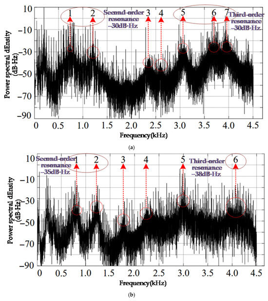
Figure 14.
42-slot and 53-slot rotor vibration spectrogram: (a) original 42-slot rotor vibration spectrum diagram; (b) optimized vibration spectrum diagram of the 53-slot rotor.
Figure 14 shows the 42-slot and 53-slot rotor vibration spectrogram, where the label represents the number of the fluctuation points. The peak values at the second-order mode shapes labeled 1 and 2 in the optimized 53-slot rotor vibration spectrum are −35 dB·Hz, which is a decrease of 5 dB·Hz compared to the original 42-slot rotor. The points labeled 3 and 4 are fluctuation points caused by motor vibration and are not resonance points, so they are not analyzed further; The peak value at the third-order mode at point 5 is −35 dB·Hz, a decrease of 5 dB·Hz compared to the original 42-slot rotor; the amplitude of the third-order resonance peak at point 6 is −38 dB·Hz, a decrease of 18 dB·Hz compared to the original 42-slot rotor.
The above analysis demonstrates that optimizing the number of rotor slots and the rotor slot pitch distance can attenuate the radial electromagnetic force waves causing motor resonance, thereby reducing electromagnetic vibration and noise in the motor. Theoretical analysis and experimental testing consistently show that the optimized motor exhibits higher electromagnetic torque performance and lower electromagnetic vibration noise, validating the correctness and feasibility of this optimization strategy.
The proposed structural optimization scheme for induction motors—combining rotor slot count and skewed slot distance—establishes a structural foundation for noise suppression in electric vehicle induction motors. Future research may explore directions such as integrating dynamic control algorithms [22], developing adaptive noise reduction systems [23], and advancing multiphysics co-design [24].
7. Conclusions
This research primarily investigates the electromagnetic noise generated by induction motors in electric vehicles and explores methods for its suppression. It establishes finite element models of induction motors with different numbers of rotor slots and different slot angles and compares and analyzes the radial electromagnetic force waves, air gap magnetic flux harmonics, and electromagnetic vibration characteristics of the motors before and after optimization. The following conclusions are drawn:
- (1)
- The original motor, with a stator and rotor slot configuration of 36/42, results in the presence of second-order radial electromagnetic force waves in the air gap, caused by the interaction between the first-order tooth harmonics of the stator and rotor and the fourth-order harmonics of the stator and rotor windings. The dominant frequency of this force wave reaches 4600 Hz, significantly exceeding the second-order natural mode of conventional small induction motors, making it prone to wide-band resonance coupling with the motor structure; Moreover, the magnetic flux density and electromagnetic force waves demonstrate irregular distribution and significant fluctuations under the spatio-temporal conditions of 140–160 ms and 0–360°, respectively;
- (2)
- For motors with rotor slot numbers ranging from 47 to 54 slots, considering the characteristics of electromagnetic force wave orders and structural resonance mechanisms, the harm caused by second-order force waves is greater than that of first- and third-order force waves. Consequently, regarding the perspective of weakening radial electromagnetic force waves, the optimal configuration for stator and rotor slot coordination is 36/53;
- (3)
- The 36/53 slot motor obtained after preliminary optimization generally has a harmonic content above 10% for the 17th, 19th, 35th, and 37th harmonics in the air gap magnetic flux density, with the highest harmonic content exceeding 20%; When the distance of the rotor skew slots is 1.0 times the stator tooth pitch, the amplitude of various harmonics in the air gap magnetic flux density is reduced to 3.49%, 1.98%, 0.732%, and 9.17% of the straight slot case, respectively; When the rotor skew slot distance is 1.2 times the stator tooth pitch, the 25th, 29th, 21st, 22nd, 32nd, and 33rd harmonics are further suppressed based on the reduction effect at 1.0 times the skew slot distance. Therefore, for this 53-slot motor, a rotor skew of 1.2 times the stator tooth pitch is the optimal choice;
- (4)
- An electric motor drag test platform was established. The measured values of torque at base speed point, torque at maximum speed point, efficiency at base speed point, and efficiency at maximum speed point showed deviations of 7.5%, 6.9%, 4.7%, and 8.8%, respectively, from their design values. All deviations remained within the allowable tolerance range, confirming the consistency between theoretical analysis and actual testing. Simultaneously, the optimized motor achieved increases of 4.8% and 11.9% in maximum electromagnetic torque at base speed and maximum electromagnetic torque at peak speed, respectively, validating the effectiveness of the optimization strategy.
- (5)
- After optimizing the number of slots and the skewed slot distance, the vibration peak at the second natural frequency decreased by 5 dB·Hz compared to the pre-optimization, while the vibration peak and resonance peak at the third natural frequency decreased by 5 dB·Hz and 18 dB·Hz, respectively, compared to the pre-optimization condition.
Against the backdrop of rapid development in the electric vehicle industry, research on suppressing electromagnetic vibration and noise in induction motors has become a core issue for enhancing overall vehicle NVH performance, strengthening market competitiveness, and promoting sustainable industry development [25,26]. The requirement for minimal noise in electric vehicle drive systems is becoming increasingly rigorous. Electromagnetic vibrations from induction motors, as a primary power source, directly influence ride comfort and driving safety via structural resonance and electromagnetic noise. This research presents significant advancements in electromagnetic noise reduction techniques for induction motors, offering essential technological support for the premium and intelligent evolution of electric vehicles, establishing a key direction for industry-wide technological advancement.
Author Contributions
Conceptualization, T.Y.; Methodology, Y.L.; Software, Y.L.; Validation, X.C. and L.L.; Formal analysis, Y.W.; Investigation, Y.W.; Resources, S.B.; Data curation, S.B.; Writing–original draft, Y.M.; Writing–review & editing, X.C.; Project administration, L.L. and S.B.; Funding acquisition, T.Y. and L.L. All authors have read and agreed to the published version of the manuscript.
Funding
This research was funded by the Science and Technology Research Program of Chongqing Municipal Education Commission, grant number KJQN202403210, Doctoral Research Foundation of Chongqing Industry Polytechnic College, grant number 2022GZYBSZK1-04 and Chongqing City Natural Science Foundation Project, grant number CSTB2022NSCQ-MSX0430.
Data Availability Statement
The datasets generated and analyzed during the current study are not publicly available due to protect study participant privacy. However, they are available from the corresponding author upon reasonable request.
Conflicts of Interest
Author Shibo Bin was employed by the company China Dongfeng Liuzhou Motor Co., Ltd. The remaining authors declare that the research was conducted in the absence of any commercial or financial relationships that could be construed as a potential conflict of interest.
References
- Peng, C.; Wang, D.; Wang, B.; Li, J.; Wang, C.; Wang, X. Different rotor segmented approaches for electromagnetic vibration and acoustic noise mitigation in permanent magnet drive motor: A Comparative Study. IEEE Trans. Ind. Electron. 2024, 71, 1223–1233. [Google Scholar] [CrossRef]
- Zhang, Y.; Xu, X.; Song, Y.; Qi, W.; Guo, Q.; Li, X. Real-Time Global Optimal Energy Management Strategy for Connected PHEVs Based on Traffic Flow Information. IEEE Trans. Intell. Transp. Syst. 2024, 25, 20032–20042. [Google Scholar] [CrossRef]
- Rangarajan, S.S.; Shiva, C.K.; Collins, E.R.; Senjyu, T. Electric Vehicle Motors Free of Rare-Earth Elements—An Overview. Machines 2025, 13, 702. [Google Scholar] [CrossRef]
- Dong, Z.; Huang, R.; Liu, S.; Liu, C. Analysis of Winding-Connection Sequence in Multiphase Series-End Winding Motor Drives for Leg-Current Stress Reduction. IEEE Trans. Ind. Inform. 2025, 21, 1635–1644. [Google Scholar] [CrossRef]
- Dong, Z.; Huang, R.; Liu, Y.; Zhao, G.; Liu, C. Emerging Electric Machines and Drives for Wind Power Generation. IEEE Trans. Magn. 2025, 61, 1–10. [Google Scholar] [CrossRef]
- Du, G.; Cui, C.; Li, L.; Li, N.; Lei, G.; Zhu, J. Comprehensive Performance Analysis of High-Speed PM Motors With Layered Rotor Structures. IEEE Trans. Ind. Electron. 2025, 72, 3460–3470. [Google Scholar] [CrossRef]
- Zhao, H.S.; Chu, C.Y.; Eldeeb, H.H.; Zhan, Y.; Xu, G.; Mohammed, O.A. Optimal design of high-speed solid-rotor cage induction motors considering ferromagnetic materials behavior and manufacturing process. IEEE Trans. Ind. Appl. 2020, 56, 4345–4355. [Google Scholar] [CrossRef]
- Deng, W.; Zuo, S. Electromagnetic vibration and noise of the permanent-magnet synchronous motors for electric vehicles: An Overview. IEEE Trans. Transp. Electrif. 2019, 5, 59–70. [Google Scholar] [CrossRef]
- Di nardo, M.; Marfoli, A.; Degano, M.; Gerada, C.; Chen, W. Rotor design optimization of squirrel cage induction motor—Part II: Results Discussion. IEEE Trans. Energy Convers. 2021, 36, 1280–1288. [Google Scholar] [CrossRef]
- Mallik, S.; Mallik, K.; Barman, A.; Maiti, D.; Biswas, S.K.; Deb, N.K.; Basu, S. Efficiency and cost optimized design of an induction motor using genetic algorithm. IEEE Trans. Ind. Electron. 2017, 64, 9854–9863. [Google Scholar] [CrossRef]
- Wang, C.Y.; Bao, X.H.; Xu, S.; Zhou, Y.; Xu, W.; Chen, Y. Analysis of vibration and noise for different skewed slot-type squirrel-cage induction motors. IEEE Trans. Magn. 2017, 53, 1–6. [Google Scholar] [CrossRef]
- Takahashi, Y.; Fujiwara, K.; Sugahara, K.; Matsuo, T. Model order reduction of cage induction motor with skewed rotor slots using multiport Cauer ladder network method. IEEE Trans. Magn. 2023, 59, 1–4. [Google Scholar] [CrossRef]
- Milažar, I.; Žarko, D. Influence of Rotor Slot Number on Magnetic Noise in a Squirrel-cage Induction Motor for Traction Applications. In Proceedings of the 2021 International Conference on Electrical Drives & Power Electronics (EDPE), Dubrovnik, Croatia, 22–24 September 2021; pp. 243–248. [Google Scholar]
- Darjazini, A.; Karimi, M.; Saeedinia, M.H.; Cheraghi, M. Vibration and Noise Analysis of Squirrel Cage Induction Motors with Double Non-Skewed Rotor Structure. In Proceedings of the 2022 13th Power Electronics, Drive Systems, and Technologies Conference (PEDSTC), Tehran, Iran, 1–3 February 2022; pp. 212–217. [Google Scholar]
- He, Z.; Jin, H.; Hou, F.; Yang, B.; Liu, S.; Zhi, Q. The Influence of Rotor Chute on Vibration and Noise of Induction Motor. In Proceedings of the 2022 IEEE 17th Conference on Industrial Electronics and Applications (ICIEA), Chengdu, China, 16–20 December 2022; pp. 250–255. [Google Scholar]
- Xu, Q.; Wang, Y.; Miao, Y.; Zhang, X. A Double Vector Model Predictive Torque Control Method Based on Geometrical Solu-tion for SPMSM Drive in Full Modulation Range. IEEE Trans. Ind. Electron. 2025, 72, 5558–5568. [Google Scholar] [CrossRef]
- Wang, X.; Wang, D.; Peng, C.; Wang, B.; Wang, X. Torsional Vibration Analysis and Suppression of Interior Permanent Magnet Synchronous Motor with Staggered Segmented Rotor for Electric Vehicles. IEEE Trans. Transp. Electrif. 2024, 10, 6285–6294. [Google Scholar] [CrossRef]
- Wang, J.; Hong, Y.; Sun, Y.; Cao, H. Effect Comparison of Zigzag Skew PM Pole and Straight Skew Slot for Vibration Mitigation of PM Brush DC Motors. IEEE Trans. Ind. Electron. 2020, 67, 4752–4761. [Google Scholar] [CrossRef]
- Di nardo, M.; Marfoli, A.; Degano, M.; Gerada, C. Rotor slot design of squirrel cage induction motors with improved rated efficiency and starting capability. IEEE Trans. Ind. Appl. 2022, 58, 3383–3393. [Google Scholar] [CrossRef]
- Rahmani, M.; Darabi, A.; Deylami, F.P. Impact of the stator coil pitch on acoustic noise and vibration of squirrel cage induction motors. IEEE Trans. Energy Convers. 2023, 38, 2344–2352. [Google Scholar] [CrossRef]
- Le besnerais, J.; Lanfranchi, V.; Hecquet, M.; Lemaire, G.; Augis, E.; Brochet, P. Characterization and reduction of magnetic noise due to saturation in induction machines. IEEE Trans. Magn. 2009, 45, 2003–2008. [Google Scholar] [CrossRef]
- Hsu, C.-H. Fractional order PID control for reduction of vibration and noise on induction motor. IEEE Trans. Magn. 2019, 55, 1–7. [Google Scholar] [CrossRef]
- Dayong, N.; Hongyu, S.; Aoyu, X.; Yongjun, G.; Hongwei, D.; Jiaoyi, H. Adaptive noise reduction method of synchronous hydraulic motor acoustic signal based on improved dislocation superposition method. IEEE Access 2020, 8, 37161–37172. [Google Scholar] [CrossRef]
- Pi, C.; Jiang, B. Vibration characteristics analysis of vehicle in-wheel motor based on multi-physical field coupling. In Proceedings of the 2024 IEEE 7th International Electrical and Energy Conference (CIEEC), Harbin, China, 10–12 May 2024; pp. 4412–4417. [Google Scholar]
- Xu, W.; Yang, T.; Miao, Y. Dead-time compensation and single-loop control strategy for ground power unit. Energy Rep. 2024, 11, 2983–2990. [Google Scholar] [CrossRef]
- Wang, D.; Peng, C.; Li, J.; Wang, C. Comparison and experimental verification of different approaches to suppress torque ripple and vibrations of interior permanent magnet synchronous motor for EV. IEEE Trans. Ind. Electron. 2023, 70, 2209–2220. [Google Scholar] [CrossRef]
Disclaimer/Publisher’s Note: The statements, opinions and data contained in all publications are solely those of the individual author(s) and contributor(s) and not of MDPI and/or the editor(s). MDPI and/or the editor(s) disclaim responsibility for any injury to people or property resulting from any ideas, methods, instructions or products referred to in the content. |
© 2025 by the authors. Licensee MDPI, Basel, Switzerland. This article is an open access article distributed under the terms and conditions of the Creative Commons Attribution (CC BY) license (https://creativecommons.org/licenses/by/4.0/).