Abstract
This paper presents the results of the research of a drive with a three-phase switched reluctance motor (SRM) with a C-dump converter, supplied from a mains rectifier. Using the tested C-dump converter for a three-phase mains-powered SRM, a significant increase in output power and speed range was achieved, with a limited capacitor charging voltage close to the source supply voltage, compared to a drive with a converter based on asymmetric half-bridges. Previous studies have only included a battery-powered drive with a two-phase motor with a capacitor charging voltage many times higher than the source voltage. The converter is designed for drives that do not require braking with energy recovery, such as fans and pumps. The mathematical model of the drive is discussed and the simulation results are presented. Experimental tests of the drive were carried out to verify the simulation results. The characteristics of the tested drive were compared with the characteristics of the drive with a typical power supply system.
1. Introduction
The basic system used to power Switched Reluctance Motors (SRM) is a converter consisting of asymmetric H-bridges. This converter is most often used to power an SRM and contains (2m) transistors, where m is the number of motor phases. The use of a full transistor bridge (4m transistors) is not necessary because the reluctance torque does not depend on the direction of current flow. This type of converter is mainly used to prevent current asymmetries resulting from changes in the magnetic flux path [1].
The schematic of the single-phase SRM converter with an asymmetric H-bridge is shown in Figure 1.
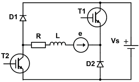
Figure 1.
Converter with an asymmetric H-bridge for one SRM phase [1].
Theoretically, the ideal way to power the motor would be to magnetize the phase and return energy to the power supply source with rectangular current waveforms in the range of the rotation angle, in which the electromagnetic torque has a positive value. However, this is prevented by the inertia of the electrical system, which limits the speed of changes in the current value in the windings. In real systems, accelerating these processes is possible in two ways: by reducing the inductance of the phase windings or by increasing the supply voltage. However, both of these methods result in deterioration of the motor power supply conditions in the range of low rotational speeds, in which the motor operates in a current limiting state or at a voltage reduced by the PWM method. In both cases, the switching frequency of the transistors and the associated commutation losses increase.
The solution is a system that allows for supplying the windings with low voltage in the range of low speeds, and increased voltage in the range of high speeds. One of the possible ways to implement this issue is to use dynamic energy sources. Using a capacitor as an additional energy source allows for controlling the voltage value during magnetization and energy return to the source.
There are also known SRM converter topologies containing a smaller number of transistors. In this case, however, it is necessary to use additional elements that allow for accelerating the process of energy discharge from the motor windings, such as resistors and capacitors [2,3,4].
The literature reports several C-dump converter topologies that achieve drive performance similar to that of asymmetric H-bridge systems [5,6]. Further examples of systems using capacitors to store energy returned from the motor are presented in [3,7,8,9,10,11,12,13]. The use of C-dump or multi-level converters with a number of transistors of 2 m or more allows the acceleration of the processes of rising and falling phase currents compared to the basic system. In this way, it is possible to increase the drive power and speed range or reduce torque pulsations [14,15,16,17,18,19,20,21,22]. These types of converters are often applied in applications where minimizing torque pulsation is crucial [2,23,24,25,26,27,28].
The rate of change in phase currents in SRMs powered from voltage sources varies with rotor position, due to the dependence of phase inductance on both rotor angular position and phase current. These transient processes can be accelerated by increasing the supply voltage. However, increasing the supply source voltage worsens the supply conditions in the low-speed range, where the motor operates at reduced voltage or under current-limiting control. For this reason, one effective approach is to supply the phases with a higher voltage only after switching on, and then to reduce the voltage after reaching the set current value. Similarly, to accelerate the discharge of magnetic field energy, it can be recovered through a higher-voltage energy path. C-dump converters offer such possibilities.
An alternative to this solution may be the use of multilevel converters, but due to the significantly larger number of semiconductor elements and their cost, they have no practical application in low-power drives [29,30,31,32].
An additional advantage of this method is the increase in the electromagnetic torque during switching of the supply of subsequent phases. This effect can be achieved by using the C-dump converter containing 2m transistors as shown in Figure 2 [33].
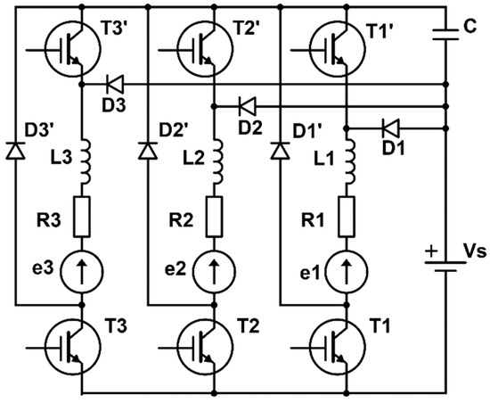
Figure 2.
The tested C-dump converter for three-phase SRM [33].
In this schematic, the symbols Lk, Rk and ek in Figure 2 represent the motor phase winding parameters. This converter allows for the improvement of some SRM output parameters in relation to the drive based on asymmetric H-type bridges.
The paper’s C-dump converter technology cannot bypass the capacitor to return energy to the primary power source. The converter is only suited for fans and pumps that do not require brakes with energy recovery due to its design.
Initial tests of this system were previously carried out for a low-voltage motor powered by batteries. They gave good results in the form of increased power and, in particular, extended speed control range [33]. In the case of a low-voltage motor, the maximum capacitor voltage was many times greater than the voltage of the power source, allowing for multiple accelerations of the phase current rise and fall processes. When powered by power grid rectifiers, C-dump systems’ maximum capacitor voltage matches the supply source voltage. The phase supply voltage is limited to twice the source voltage by the winding insulation’s allowed voltage. This limits phase voltage increases compared to low-voltage drives where capacitor voltage might be many times the supply voltage.
The use of the C-dump converter discussed in the article for a drive powered by a mains rectifier significantly limits the possibility of increasing the phase voltages. C-dump converters in low-voltage drives with SRMs enable supplying phase windings with a voltage many times higher than the supply voltage, which accelerates the processes of rising and falling phase currents and improves the drive characteristics.
Compared with the existing works, the main contributions of this paper are listed as follows: in the presented drive, the maximum value of the capacitor charging voltage is limited to a value close to the supply source voltage. This limitation results from the maximum voltage of the C-dump capacitor, the maximum voltage of the transistors and, above all, the permissible insulation voltage of the phase windings. Therefore, the motor supply voltage can only be increased to approximately twice the source voltage. In this converter, the phase voltage during energy return is close to the supply source voltage.
Therefore, the possibility of using this type of converter in a mains-powered drive with a three-phase motor was checked. In three-phase motors, the angular range of magnetic field energy discharge from the windings is twice as wide as the angular range of phase supply. Therefore, the permissible energy discharge time can be twice as long as the phase supply time. The main objective of the work was to determine the influence of the tested C-dump converter used in a three-phase mains-powered drive on the output characteristics of this drive and to determine the relative increase in power and the maximum speed range. The article presents for the first time research on the possibilities of using the presented C-dump converter in a drive powered from the power grid.
2. Model of the SRM Drive
The switched reluctance motor (SRM) generates electromagnetic torque due to changes in the reluctance of the magnetic circuit as a function of the rotor position angle. The rotor tends to take the position in which its equivalent magnetic reluctance is the smallest [1].
The mathematical model of the motor does not take into account the phenomena of mutual magnetic coupling between the windings of different phases, eddy currents, and hysteresis of the magnetic circuit.
The SRM model should take into account the nonlinearity characteristic of the magnetic circuit, which has a dominant effect on the drive characteristics.
In the simulation model, interpolated characteristics obtained from magnetic field calculations for different values of the rotation angle and phase current were used for the calculations. The final form of the equation for the mechanical system is presented as (1).
The final form of the electric equations, assuming no mutual magnetic couplings, is presented as (2)
Taking into account the dependence of the magnetic flux on the rotor position angle and the phase current, the relationship (3) is obtained
where
is the electromotive force of transformation, while
is the electromotive force of rotation, which has a significant influence on the rate of rise currents in the high-speed range.
The final form of the equation for electric circuits is given by (4).
It follows from (4) that the basic reason for the decrease in the value of phase currents, and consequently of the electromagnetic torque, in the range of high rotational speeds, is the limited speed of the rise and fall of the phase currents caused by the increase in the electromotive force of rotation.
The decrease in the average value of the phase current can be limited by increasing the supply voltage. The basic power supply system of SRMs is a converter consisting of asymmetric H-bridges.
The asymmetric H-bridge circuit can operate in one of three operating states: magnetization, demagnetization and energy return to the power supply. The magnetization state is achieved with both transistors switched on. The rate of current rise in this operating state is slightly lower than in the simplest converter, due to the voltage drop in the additional transistor in the phase supply circuit. The rate of current rise in this operating state is described in (5).
In the demagnetized state, one of the transistors is turned on, and the other is turned off; there are two such states, with transistor T1 or T2 switched on. This state can be used to limit the phase current or regulate the supply voltage, e.g., using the pulse width modulation (PWM) method. This state is described by Equation (6).
The next is the state of energy return to the power supply, which is obtained after turning off both transistors. The energy of the magnetic field is returned to the power supply by the diodes. The rate of the current value falling in this state is described by (7). It is slightly greater than the rate of current rise in the supply state (8).
Presented C-dump converter can operate in four states. The first is the higher voltage magnetization state from a power source and capacitor connected in series; this state is obtained after switching on both transistors with the charged C-dump capacitor. In this mode, the phase is initially supplied with the maximum voltage, which is the sum of the power supply voltage and the maximum capacitor voltage. During operation, the supply voltage is falling as the capacitor discharges. The rate of phase current rise in this state is described by (9).
Depending on the control algorithm, during power supply the capacitor voltage drops to a set minimal value, at which the transistor connected to the capacitor is switched off or the capacitor is completely discharged. Then the system switches to powering the phase from the power source via a diode. The phase current rise rate in this state is described by (10).
When both transistors are switched off, the system returns energy to the capacitor. Then the C-dump capacitor is charged. The current in the phase windings decreases in accordance with (11).
After reaching the maximum value of the capacitor charging voltage, the transistor connected to the capacitor is switched on, and the other transistor remains off. The system works in the idle loop state. The rate of current falling in this state is determined by (12).
This system enables acceleration of the processes of rising and falling phase currents, compared to the system based on asymmetric bridge type H. The average values of the supply voltage during magnetization and energy return are similar (13); therefore the times of current rise and decay are also similar, unless other operating states are used.
The simulation calculations were performed for a three-phase motor, the data of which are given in Table 1.

Table 1.
The data of a motor.
The motor characteristics were determined in the FEMM program. Calculations were performed using the finite element method. The calculations of the magnetic flux and electromagnetic torque were performed for different position angles of the rotor, determined in relation to the position of rotor minimum reluctance. Due to the omission of mutual magnetic couplings in the mathematical model, the calculations were performed for different values of the current in one phase. The resulting dependencies for the magnetic flux were interpolated using third-order splines and then transformed into dependencies of the phase current on the rotation angle and magnetic flux (Figure 3), and the electromagnetic torque on the angular position of the rotor and the phase current (Figure 4).
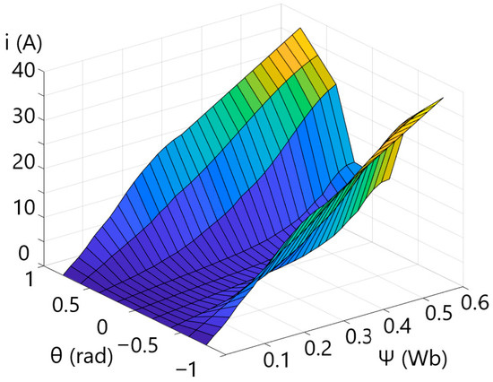
Figure 3.
Dependence of the phase current i on the magnetic flux ψ and rotor position angle θ.
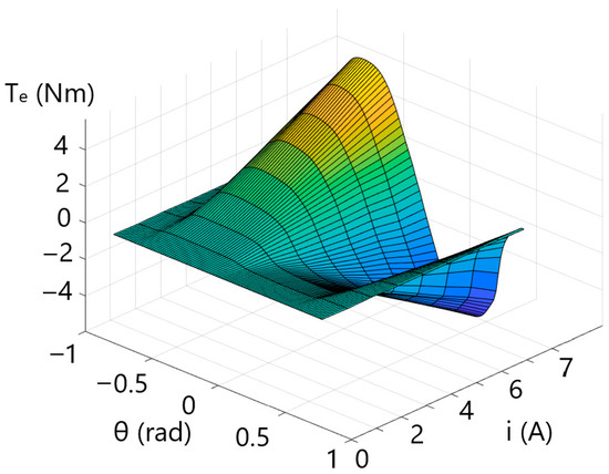
Figure 4.
Dependence of the electromagnetic torque Te on the rotor position angle θ and the phase current i.
The simulation model shown in Figure 5 was adapted for calculations at a constant load torque. This model based on the parameters of the power supply system and is consistent with the experimental system. Two versions of the program were developed with different converters: with asymmetric H-type bridges and with a C-dump system.
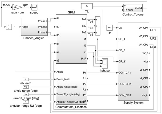
Figure 5.
Simulation model of the SRM drive in MATLAB Simulink.
The simulation program was developed in Matlab Simulink 2024b. The general structure of the simulation program is shown in Figure 5. The diagram contains three basic modules: the SRM, an electronic commutator that switches power to the individual phases depending on the angular position of the rotor and the converter.
The commutator module generates pulses controlling the power supply to the motor phases. The same power supply ranges were established for all phases, and angular shifting was achieved by feeding the converters with 30-degree phase-shifted rotation angle values from additional modules.
The converter module varied depending on the type of converter being tested. In the case of the half-bridge system, it was controlled based on the rotor angular position, taking into account the current limit. In the C-dump system, the capacitor charging and discharging process was additionally controlled according to the assumed voltage range.
3. Experimental Research
In order to verify the results obtained from the calculations in the simulation program, experimental tests of the drives were carried out. The block diagram of the experimental test stand is shown in Figure 6.
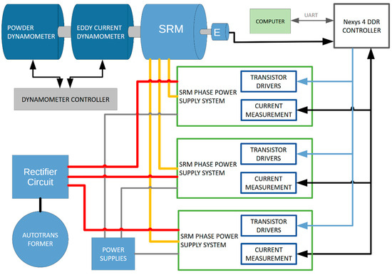
Figure 6.
Block diagram of the test stand.
Using this stand, measurements of torque, rotational speed, phase and supply currents and voltages were carried out for various operating points of the drives, with the motor powered from a converter based on asymmetric H-bridges and from a C-dump converter.
The laboratory stand is shown in Figure 7. The Magtrol (Buffalo, NY, USA) dynamometer, motor, and power supply system consist of configurable power electronic modules and a controller based on a programmable Xilinx Artix 7 FPGA system (San Jose, CA, USA). The power electronic modules enable the configuration of a system consisting of asymmetric H-bridges and a C-dump converter. The controller allows control of supply voltage, the switch-on and switch-off angles of the phase power supply, the value of the current limit, and the values of the capacitor charge and discharge voltages.
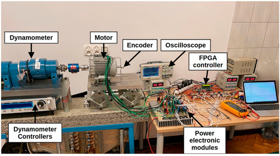
Figure 7.
Laboratory stand: eddy current dynamometer, motor, configurable power electronic modules, controller based on a programmable FPGA system.
Incorrect capacitance or voltage range regulation can cause uneven capacitor charging and discharging, affecting motor speed and torque. If the capacitor’s capacitance is too high or the voltage range is too wide, it may take several power supply cycles to charge to its maximum value, affecting drive operation. Figure 8 shows the waveforms of the signal controlling the power supply of one phase (purple), phase current (green), capacitor voltage (blue) and supply current (red).
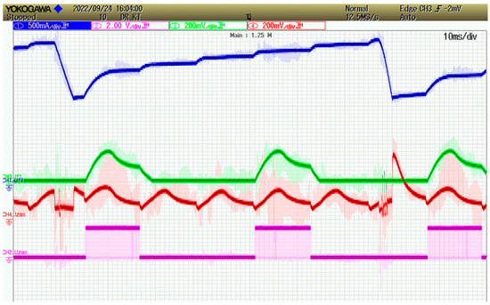
Figure 8.
Waveforms for too large a capacitance of the C-dump capacitor: control signal (purple), voltage (blue) and current waveforms (green—phase current ic, red—supply current is).
It shows the gradual recharging of the capacitor in several power supply cycles before reaching the discharge voltage. At the beginning of the sixth cycle, the voltage reaches the maximum value and the phase windings are supplied from the series-connected power source and capacitor. Due to the supply of the phase windings with a higher voltage, a much faster increase in the phase current is visible. The phase current reaches a much higher value than in the previous cycles. This can cause uneven operation of the motor.
With the correct selection of capacitance and voltage range control, the capacitor should be charged to its maximum value in each power supply cycle. In the example shown in Figure 8, the phases are supplied unevenly, which causes fluctuations in the speed and torque of the motor.
Figure 9 shows the effect of too late charging the capacitor on the phase current waveform. Initially, the phase is supplied with current from the source Vs. In the final part of the phase current waveform (green waveform), a rapid increase in the phase current value is visible (Figure 9, sign A), approximately halfway through the phase supply cycle. The initial slow increase in current results from supplying the windings from the power source itself. After reaching the maximum capacitor voltage value, it is discharged, as a result of which the windings are supplied with a higher voltage. This waveform shows the difference in the speed of the phase current increase, when the motor is supplied from the source itself and with the voltage increased by the capacitor voltage.
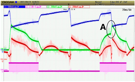
Figure 9.
Current and voltage waveforms in the C-dump converter with the visible effect of supplying a higher voltage: colour blue—capacitor voltage, green—phase current ic, red—supply current is, purple—signal controlling of one phase (on/off).
Thanks to the increase in the speed of the phase current rising, it is possible to obtain the rated current value for the much higher rotational speeds than in the asymmetric H-bridge. At the same time, in the range of low speeds, it is possible to supply the motor with the rated voltage through a diode and operate in the current limiting mode, switching the system to the idle loop state (Figure 10).
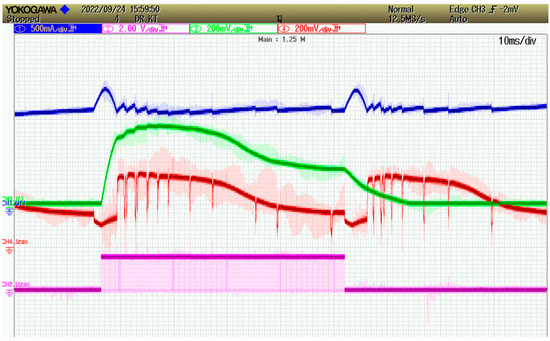
Figure 10.
Current and voltage waveforms in the C-dump converter for low rotational speeds during operation in current limitation: colour blue—capacitor voltage, green—phase current ic, red—supply current is, purple—signal controlling of one phase (on/off).
On the other hand, there may be conditions when the capacitor is charged and discharged multiple times in power supply cycle of a phase (Figure 11). Such conditions may be caused by too small a capacitor capacitance or too small a difference between the maximum and minimum capacitor voltages. Such conditions may affect the deterioration of drive operation.

Figure 11.
Phase voltage waveform with multiple full discharge of the capacitor (simulation).
Based on the measurement results, it can be concluded that the control of the presented C-dump system requires the adjustment of the system parameters and the power supply method to the motor’s rotational speed. Additionally, in order to maintain high torque and high efficiency, it is also necessary to adjust the angular supply range of the motor phase to the momentary rotational speed of the rotor.
4. Verification of Calculation Results
The verification of calculation results was carried out for both types of drives, based on asymmetric H-bridges and on the tested C-dump converter. The verification of results for the C-dump system was carried out in the initially determined angle ranges, in which the capacitor was charged and discharged in each supply cycle.
Figure 12 shows the dependence of the rotational speed of the motor supplied from asymmetric H-bridges on the switch-off angle, with a constant supply range of 30°. Figure 13 shows similar dependencies for the motor output power. The continuous lines show the approximated calculation results, while the points show the measurement results.
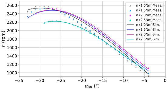
Figure 12.
Dependences of the rotational speed n on the switch-off angle αOFF for different values of the load torque in the drive with asymmetric H-bridges.
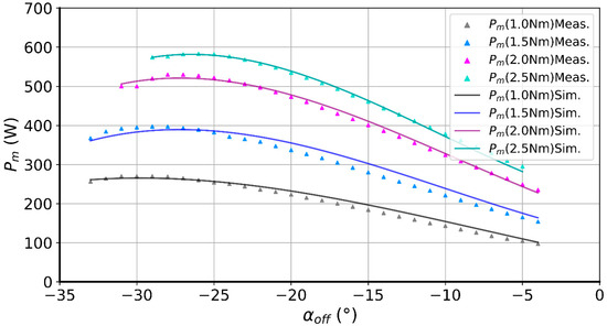
Figure 13.
Dependences of the motor output power Pm on the switch-off angle for different values of the load torque in the drive with asymmetric H-bridges.
The corresponding phase current dependencies are shown in Figure 14. There are clear minima in the phase current dependencies on the switch-off angle. For large switch-off angle values, the phase currents increase with a simultaneous decrease in power value (Figure 14). This is caused by the high value of phase currents in the braking angle range. Operation in this range is not effective.
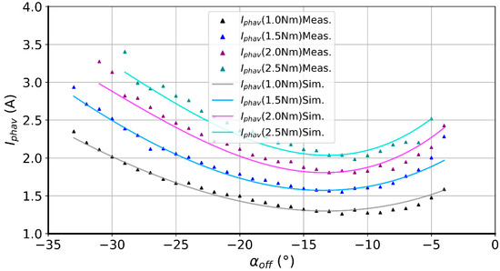
Figure 14.
Dependence of the average phase current Iphav value on the switch-off angle (Meas.—measurement, Sim.—simulation).
Additional verification of the calculation results was performed for the drive with the tested C-dump system. For this converter, the results were verified in the part that differs from the asymmetric H-bridge system, i.e., the operation of the C-dump capacitor charging and discharging circuit.
Due to the lack of a determined dependence of the optimal commutation angles on the rotational speed, the measurements were performed at a reduced supply voltage. The measurements in the C-dump system were performed for different maximum and minimum values of the capacitor voltage. The measurement conditions were selected in such a way that the capacitor was charged and discharged only once in each power supply cycle. The measurement and calculation results are presented in Table 2 for Vs = 50 V and Table 3 for Vs = 85 V.

Table 2.
Comparison of measured and calculated values of rotational speed and supply current at different maximum and minimum capacitor voltage values (Vs = 50 V, αoff = −25°).

Table 3.
Comparison of measured and calculated values of rotational speed and supply current at different maximum and minimum capacitor voltage values (Vs = 85 V, αoff = −25°).
The verification carried out showed that the calculation results were convergent with the measurement results, so the characteristics were determined in a simulation program. Particularly good convergence of results was obtained in the middle part of the angle range, i.e., in the range used mainly in the drive control process. The results obtained for the extreme values of angles have no practical significance because they are outside the area of optimal dependencies of control angles on speed, determined during further tests. Therefore, the determination of the dependencies of control angles, the ranges of capacitor charge and discharge voltages, and the drive output characteristics was performed by simulation.
5. Comparative Study of the Drives
During the tests, calculations in the range of low rotational speeds, at reduced supply voltage or in the current limiting state were omitted. They do not affect the increase in power and the drive speed range. All calculations were performed at the rated supply voltage of the motor. Calculations were performed in the established switch-off angle ranges, with a constant width of the phase supply range of 30-degree angle. The tests were conducted using a 100 µF C-dump capacitor, whose value was determined based on prior experimental results, within defined voltage ranges for charging and discharging.
Comparative study of the drive with a C-dump converter and a converter composed of asymmetric H-bridges was carried out by supplying the system with rated voltage. The purpose of the study was to determine the possibility of increasing the power and speed range of the drive by using the C-dump converter under test, with similar power source and capacitor charging voltages. Calculations of the parameters of both drives were carried out in the adopted calculation grid of the following values: switch-off angle, load torque, and capacitor charging and discharging voltages.
During the tests, the capacitor was charged to various voltages and discharged in the range of 10–90% of the charging voltage. This allowed a different quantity of energy stored in the magnetic field of the motor to be returned to the capacitor. Based on the results of these calculations, output characteristics were determined by assuming maximization of drive power over the entire speed range, as well as corresponding drive control characteristics.
The characteristics shown in Figure 15 (for maximum output power) were obtained based on a set of calculation results for various load torque values, switch-off angles, and capacitor charge and discharge voltages, within a given calculation grid. The resulting solutions were then presented in the coordinate system Pm = f(n). Finally, the solutions for which maximum output power values were obtained were selected and interpolated. The resulting set of points formed the basis for developing all the remaining characteristics.
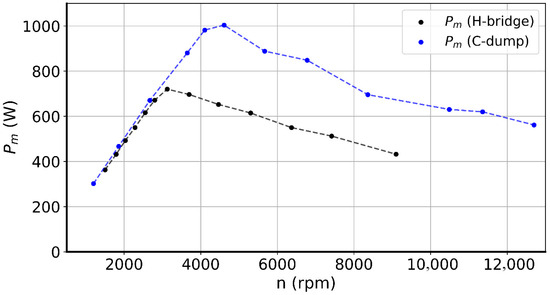
Figure 15.
Dependence of motor output power Pm on motor speed for a C-dump converter (blue) and a converter based on asymmetric H-bridges (black), for power maximization condition.
For this purpose, the following values were determined for each of the selected points with maximum power: torque (Figure 16), phase supply switch-off angle (Figure 17), capacitor charge and discharge voltage (Figure 18), and drive efficiency (Figure 19).
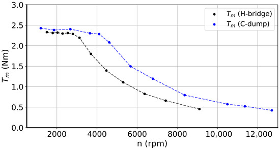
Figure 16.
Dependence of torque Tm on motor speed for a C-dump converter (black) and a converter with asymmetric half-bridges (blue) for the condition of maximizing output power.
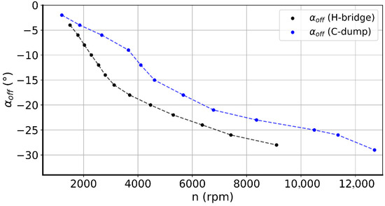
Figure 17.
Dependence of switch-off angle αoff on rotational speed for a C-dump converter (blue) and a converter based on asymmetric half-bridges (black), for power maximization condition.
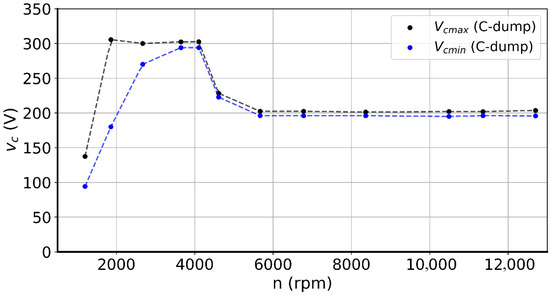
Figure 18.
Dependence of maximum capacitor maximum charging voltage VCmax (black) and minimum capacitor discharging voltage VCmin (blue) on speed for C-dump converter, for power maximization condition.
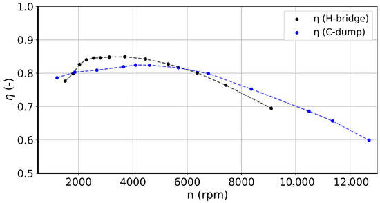
Figure 19.
Dependence of efficiency on rotational speed for a C-dump converter (blue) and a converter based on asymmetric H-bridges (black), for power maximization condition.
According to the obtained characteristics, the maximum output power of the C-dump motor increased to approximately 1000 W at a rotational speed of 4600 rpm (Figure 16). Furthermore, it has an over-rated value of 750 W at rotational speeds above 8000 rpm.
As a result of the simulation, the torque output characteristics shown on Figure 16 were determined for both the compared drives. In the lower speed range, the rated torque value was adopted. For higher speeds, the load torque value was reduced during calculations. For the drive with a converter based on asymmetrical H-bridges, the rating torque value was obtained up to a speed of 3000 rpm, which is in accordance with the motor rated data. For the drive with a C-dump converter, the torque value was constant to a speed of approx. 4100 rpm.
Table 4 presents the motor output power values obtained for both the C-dump and H-bridge converter configurations under the power maximization condition, corresponding to the characteristics shown in Figure 16. The table also includes the relative error, expressed as a percentage, with respect to the power output of the H-bridge-based drive. Table 4 shows that above 3000 rpm, the C-dump converter starts to generate much higher output power than the H-bridge converter. The difference between the two systems increases quickly with speed, reaching over 60% at 5000 rpm and up to 73% at 8500 rpm.

Table 4.
Approximated values of motor output power Pm as a function of motor speed for a C-dump converter and a converter based on asymmetric H-bridges, under the power maximization condition.
The presented characteristics (Figure 15 and Figure 16) were obtained with a constant phase supply range of 30-degree angle and the dependence of the switch-off angle on the speed shown in Figure 17. In both cases, in the low-speed range, the value of the switch-off angle is constant.
This is the speed range in which voltage regulation is used. For the higher speed up to the rated value (3000 rpm), the dependence of the switch-off angle on rotational speed is close to linear. For speeds higher than the rated speed in the system with asymmetric H-bridges, the dependence is also linear, but the slope of the characteristic is smaller.
In contrast, for a C-dump converter, in the speed range by which the constant-torque operation range is extended, the value of the switch-off angle should decrease more quickly.
In the range of operation with constant power, as in the reference system, the relationship is also close to linear, but the slope of the characteristic is smaller.
Over the entire rotational speed range, the values of the switch-off angle in the C-dump converter are larger, which means that the phase power is switched off closer to the aligned position of the rotor and stator teeth. This is due to the faster discharge of magnetic field energy from the phase windings as a result of the increase in voltage during capacitor charging. This results in a faster drop in phase current values, before the rotor enters the braking range.
In addition to changing the value of the switch-off angle, the C-dump converter requires that the values of the capacitor charging and discharging voltages depend on the rotational speed (Figure 18) in order to maximize motor output power. In the low-speed range, when the supply voltage is reduced, the capacitor should be charged to a small value, or the motor should be powered from the power supply itself through a diode. In the constant torque operating range, the capacitor should be charged to a maximum value and initially discharged to a small voltage value. Thereafter, the capacitor discharge range should be reduced and reach a minimum value at the end of the constant torque operating range. Above this speed, a small difference between the charging and discharging voltage should be maintained, while the value of the maximum charging voltage should be reduced and remain constant. For the maximum value of the charging voltage in this speed range, the power obtained was lower by several percent. Determining the reasons for such a relationship requires additional tests for different machines.
The capacitor’s charging and discharging currents increase energy losses in the C-dump converter. Drive efficiency drops by up to 5% between 2000 and 5700 rpm.
The efficiency shown in Figure 19 is defined as the ratio of mechanical power at the motor to the sum of mechanical power and total losses in the system (14).
Efficiency calculations were performed in steady states during simulation. Losses in the motor core were included in the calculations on an estimated basis. In terms of dynamic properties, both systems behave in a similar way.
Figure 20 shows the time course of the motor speed for both systems with changes in control parameters consistent with the designated operating points at rated torque load. In the converter composed of asymmetric H-bridges, the value of the turn-off angle was changed from −7.5° to −16°, while in the C-dump converter the capacitor charge and discharge voltage range was changed from 150/130 V to 300/290 V. Acceleration in both cases is similar. The visible slowdown in the speed increase in the system with asymmetric H-bridges is caused by the system going into the current limiting state.
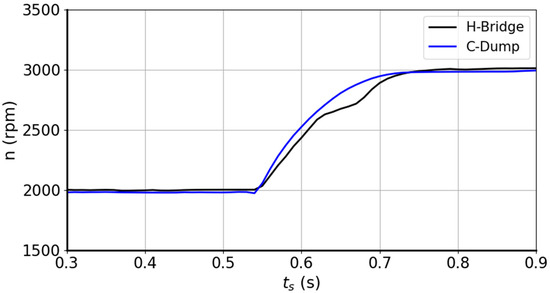
Figure 20.
Transient response of rotational speed for the C-dump converter (blue) and the H-bridge-based converter (black) under constant input voltage. Operating points were adjusted to increase speed from 2000 rpm to 3000 rpm.
6. Conclusions
The article describes the results of a comprehensive study of a SRM drive with a C-dump converter. For the first time, the properties of a drive system with the authors’ C-dump converter were examined for a three-phase motor powered from the mains to determine its suitability for this type of application. Drives of this type have significant limitations in terms of the ability to increase the motor’s supply voltage. The primary objective of the study was to evaluate the impact of using a C-dump converter on the characteristics of a three-phase mains-powered motor. In three-phase motors, the allowable energy recovery time can be twice as long as the phase supply time. An important result of the research is the increase in power and the extension of the rotational speed range of a three-phase drive with an SRM, powered from the power grid, compared to a typical drive based on asymmetric half-bridges. Therefore, this converter can be used for mains drives to power motors with three or more phases.
The maximum value of the capacitor charging voltage was assumed on the basis of the permissible value of winding insulation, at a level close to the voltage of the power source. The tests were carried out using measurement-verified simulation models of the drives. Measurements were performed for both systems on a laboratory stand, in which only the motor power supply system was changed. Measurements and calculations were carried out for a predetermined capacitance of the C-dump capacitor, allowing it to receive all the energy returned from the phase windings in each supply cycle. The tests were carried out for different values of the motor’s load torque, and different values of control quantities, such as switch-off angle, charging and discharging voltages of the capacitor. During the tests, the phase power supply angle interval was assumed constant, so that the power supply of only one phase of the motor was switched on at a time.
The study shows that to maintain high torque and efficiency, C-dump system control parameters such switch-off angles and capacitor charging/discharging voltages must be adjusted dependent on motor rotational speed. To understand performance linkages, such as power output at maximum charging voltage, additional experiments for different ma-chines are needed.
The tests carried out showed the possibility of increasing the maximum power and speed range of the drive as a result of using a C-dump converter. For the tested motor, the possibility of extending the speed range with rated torque from 3100 rpm to 4100 rpm was obtained. The result was an increase in the maximum power of the drive from 750 W to 1000 W. It is important that the increase in power is obtained at a similar RMS value of the phase current as in a converter based on asymmetrical H-bridges. Consequently, winding heating does not increase.
As a result, the drive’s operating speed range with a maximum power of 750 W has been increased from 3100 rpm (using a converter based on asymmetric H-bridges) to 8000 rpm (using a C-dump converter).
However, the use of a C-dump converter resulted in a reduction in drive efficiency by up to 5% in certain parts of the speed range. This is caused by the charging and discharging currents of the capacitor. The drop in efficiency in this range is largely due to the adopted criterion for selecting the characteristic in terms of achieving maximum drive output power. Drive efficiency can be improved by adopting a different criterion for determining the characteristic. However, adopting the efficiency-maximizing criterion will result in a reduction in drive output power.
As a result of the conducted tests, it was demonstrated that the presented C-dump converter can be used in a drive powered from the power grid, provided that an SRM with at least 3 phases is used. However, this converter can only be used to a limited extent, due to limitations on the amount of energy returned to the capacitor and the inability to return energy to the power source itself.
Author Contributions
Conceptualization, K.T. and K.W.; methodology, K.T.; software, D.R.; validation, K.T. and K.W.; formal analysis, K.W.; investigation, K.T. and D.R.; resources, D.R.; data curation, D.R.; writing—original draft preparation, K.T. and D.R.; writing—review and editing, K.T. and K.W.; visualization, D.R.; supervision, K.T. and K.W.; project administration, K.T. All authors have read and agreed to the published version of the manuscript.
Funding
This research received no external funding.
Data Availability Statement
The original contributions presented in this study are included in the article. Further inquiries can be directed to the corresponding author.
Conflicts of Interest
The authors declare no conflicts of interest.
Abbreviations
The following abbreviations are used in this manuscript:
| αOFF | Turn-off angle |
| C | Capacitance |
| D | Rotational resistance coefficient |
| Dk, Dk′ | Diode in the k-th phase branch |
| DFe | Core loss factor |
| ek | Electromotive force of phase k |
| ic | Capacitor current |
| ik | k-th phase current |
| is | Supply current |
| Iphav | Average phase current |
| Is | Average source current |
| J | Moment of inertia of the rotor |
| Lk | Inductance of k-th phase winding |
| m | Number of motor phases |
| n | Rotational speed |
| Pm | Motor output power |
| PWM | Pulse-Width Modulation |
| ΔPc | Commutation losses in power electronics |
| ΔPcu | Copper losses in winding resistance |
| ΔPe | Conduction losses in power electronics |
| ΔPFe | Motor core losses |
| ΔPm | Mechanical losses |
| Rk | Resistance of the k-th phase winding |
| RMS | Root mean square |
| SRM | Switched Reluctance Motor |
| t | Time |
| Te | Electromagnetic torque |
| TL | Load torque |
| Tm | Mechanical torque |
| Tk, Tk′ | Transistor in the k-th phase branch |
| vc | Capacitor voltage |
| vD | Diode on-state voltage |
| VCmax | Maximum capacitor charging voltage |
| VCmin | Minimum capacitor discharging voltage |
| vk | k-th phase voltage |
| Vs | Supply voltage |
| vT | Transistor on-state voltage |
| Ψk | Flux linkage of k-th phase |
| Rotor position angle |
References
- Miller, T.J.E. Switched Reluctance Motors and Their Control; Oxford University Press: Oxford, UK, 1993. [Google Scholar]
- Vijayaragavan, C.M.; Ranjan, P.V.; Velraj, R. Implementation Challenges: Universal R-Dump Converter for Switched Reluctance Motor. Int. Trans. Electr. Energy Syst. 2022, 2022, 1306544. [Google Scholar] [CrossRef]
- Kido, Y.; Moshi, N.; Ciba, A.; Ogasawara, S.; Takemoto, M. Novel switched reluctance motor drive circuit with voltage boost function without additional reactor. In Proceedings of the 2011 14-th European Conference on Power Electronics and Applications EEP 2011, Birmingham, UK, 30 August–1 September 2011; pp. 1–10. [Google Scholar]
- Krishnan, R. A Novel Converter Topology for Switched Reluctance Motor Drives. In Proceedings of the 27th Annual IEEE Power Electronics Specialists Conference PESC ‘96, Baveno, Italy, 23–27 June 1996; Volume 2, pp. 1811–1816. [Google Scholar]
- Cho, K.Y.; Lim, J.Y. Power converter circuit for a switched reluctance motor using a flyback trans-former. IEE Proc.-Electr. Power Appl. 2003, 150, 88–96. [Google Scholar] [CrossRef]
- Yong-Ho, Y.; Sang-Hoon, S.; Tae-Won, L.; Chung-Yiien, W.; Gyu-Sik, K. High Performance Control of C-dump Converters fed Switched Reluctance Motor for Automobiles. In Proceedings of the 35th Annual IEEE Power Electronics Specialists Conference Achen 2004, Achen, Germany, 20–25 June 2004; Volume 2, pp. 1322–1328. [Google Scholar]
- Jianing, L.; Dong-Hee, L.; Jin-Woo, A.; Young-Joo, A. A novel 4-level converter and instantaneous switching angle detector for high-speed SRM drive. IEEE Trans. Power Electron. 2007, 22, 2024–2041. [Google Scholar]
- Jaehyuck, K.; Krishnan, R. Novel Two-Switch-Based Switched Reluctance Motor Drive for Low-Cost High-Volume Applications. IEEE Trans. Ind. Appl. 2009, 45, 1241–1248. [Google Scholar] [CrossRef]
- Kobler, R.; Anderssner, D.; Amrhein, W. Development of a SRM power electronic system with a reduced number of power semiconductors. In Proceedings of the 3rd International Youth Conference on Energetics IYCE, Leiria, Portugal, 7–9 July 2011; pp. 1–7. [Google Scholar]
- Han, G.; Chen, H.; Guan, G. Low-cost SRM drive system with reduced current sensors and position sensors. IET Electr. Power Appl. 2018, 13, 853–862. [Google Scholar] [CrossRef]
- Gairola, S.; Priti Paliwal, L.N. A novel power converter for SRM drive. In Proceedings of the International Conference on Power, Control and Embedded Systems ICPCES, Allahabad, India, 29 November–1 December 2010; pp. 1–6. [Google Scholar]
- Bagherian, H.; Asgar, M.; Afjei, E. A new C-dump converter for bifilar winding switched reluctance motor. In Proceedings of the Power Electronics, Drive Systems and Technologies Conference PEDSTC, Tehran, Iran, 16–17 February 2011; pp. 467–472. [Google Scholar]
- Yoon, Y.H. Performance of Proposed Resonant C-dump Converter in Switched Reluctance Motor Drive. J. Electr. Eng. Technol. 2020, 15, 1911–1919. [Google Scholar] [CrossRef]
- Rolim, L.G.B.; Suemitsu, W.I.; Watanabe, E.H.; Hanitsch, R. Development of an improved switched reluctance motor drive using a soft-switching converter. IEE Proc.-Electr. Power Appl. 1999, 146, 488–494. [Google Scholar] [CrossRef]
- Ishikawa, H.; Wang, D.; Naitoh, H. A New Switched Reluctance Motor Drive Circuit for Torque Ripple Reduction. In Proceedings of the Power Conversion Conference PCC, Osaka, Japan, 2–5 April 2002; Volume 2, pp. 683–688. [Google Scholar]
- Kittiratsatcha, S.; Torrey, D.A. A Low-cost Converter for Two-phase Switched-reluctance Motor Drives. In Proceedings of the Fifth International Conference on Power Electronics and Drive Systems PEDS, Singapore, 17–20 November 2003; Volume 2, pp. 1605–1608. [Google Scholar]
- Materu, P.N.; Krishnana, R. Steady-State Analysis of the Variable-Speed Switched-Reluctance Motor Drive. Ind. Electron. IEEE Trans. Ind. Electron. 1989, 36, 523–529. [Google Scholar] [CrossRef]
- Kalpana, D.; Kumar, K.K.; Tripura, P. A multi-functional converter based switched reluctance motor drive for electric vehicle. Int. J. Power Electron. Drive Syst. IJPEDS 2022, 13, 1975–1983. [Google Scholar] [CrossRef]
- Krishnan, R.; Materu, P.N. Design of a Single-Switch-per-Phase Converter for Switched Reluctance Motor Drives. IEEE Trans. Ind. Electron. 1990, 37, 469–476. [Google Scholar] [CrossRef]
- Mir, S.; Husain, I.; Elbuluk, M.E. Energy-Efficient C-Dump Converters for Switched Reluctance Mo-tors. IEEE Trans. Power Electron. 1997, 12, 912–921. [Google Scholar] [CrossRef]
- Pollock, C.; Williams, B.W. Power convertor circuits for switched reluctance motors with the mini-mum number of switches. IEE Proc.-Electr. Power Appl. 1990, 137, 373–384. [Google Scholar] [CrossRef]
- Dahmane, A.; Meebody, F.; Sargos, F.M. A Novel Boost Capacitor Circuit to Enhance the Performance of the Switched Reluctance Motor. In Proceedings of the IEEE 32nd Power Electronics Specialists Conference PESC, Vancouver, BC, Canada, 17–21 June 2001; Volume 2, pp. 844–849. [Google Scholar]
- Badhoutiya, A.; Yadav, K. Switched Reluctance Motor with C-Dump Converter. In Proceedings of the 6th International Conference On Computing, Communication, Control And Automation (ICCUBEA), Pune, India, 26–27 August 2022; pp. 1–6. [Google Scholar]
- Abdel-Aziz, A.; Elgenedy, M.; Williams, B. Review of Switched Reluctance Motor Converters and Torque Ripple Minimisation Techniques for Electric Vehicle Applications. Energies 2024, 17, 3263. [Google Scholar] [CrossRef]
- Gaafar, M.A.; Abdelmaksoud, A.; Orabi, M.; Chen, H.; Dardeer, M. Switched Reluctance Motor Converters for Electric Vehicles Applications: Comparative Review. IEEE Trans. Transp. Electrif. 2023, 9, 3526–3544. [Google Scholar] [CrossRef]
- Asati, R.; Bankar, D.S.; Nehete, A.L. Torque Ripple Assessment of Converter Topologies for Switched Reluctance Motor. In Proceedings of the IEEE 3rd International Conference on Electrical Power and Energy Systems (ICEPES), Bhopal, India, 21–22 June 2024; pp. 1–6. [Google Scholar]
- Chaple, M.D.; Deotale, N.T.; Deotale, N.T. Torque Ripple Minimization in an 8/6 Switched Reluctance Motor Drive: Optimization Using the AZOA Method. Aust. J. Electr. Electron. Eng. 2024, 22, 27–44. [Google Scholar] [CrossRef]
- Mishra, A.; Bhattacharyya, B. Power Quality Improvement of Switched Reluctance Motor Using Different PFC Converter. In Proceedings of the IEEE 1st International Conference on Smart and Sustainable Developments in Electrical Engineering (SSDEE), Dhanbad, India, 28 February–2 March 2025; pp. 1–5. [Google Scholar]
- Kumawat, G.; Payami, S. A Multilevel Power Converter for Switched Reluctance Motors with Integrated Battery Charging Capability. In Proceedings of the IEEE Energy Conversion Congress & Exposition Asia (ECCE-Asia), Bengaluru, India, 11–14 May 2025; pp. 1–6. [Google Scholar]
- Malekpour, H.; Rashidi, A.; Saghaian Nejad, S.M.; Lee, D.-H. Multi-Level Voltage High Fault-Tolerance Modular SRMConverter With Simultaneous Charge Discharge Capability for HEV. IEEE Access 2025, 13, 127447–127461. [Google Scholar]
- Pires, V.F.; Foito, D.; Pires, A.J.; Cordeiro, A.; Martins, J.F. Fault Tolerant Multilevel Converter Based on a Reduced Switch Configuration for a 8/6 Switched Reluctance Motor Drive. In Proceedings of the IEEE 19th International Conference on Compatibility, Power Elec-tronics and Power Engineering (CPE-POWERENG), Antalya, Turkey, 20–22 May 2025; pp. 1–6. [Google Scholar]
- Chithrabhanu, A.; Vasudevan, K. A Novel Four-Level Shared Switch Converter with Buck–Boost Energy Recovery Stage for Switched Reluctance Motor Drive. IEEE J. Emerg. Sel. Top. Ind. Electron. 2025, 6, 135–145. [Google Scholar]
- Tomczewski, K.; Wrobel, K. Improved C-dump converter for switched reluctance motor drives. IET Power Electron. 2014, 7, 2628–2635. [Google Scholar]
Disclaimer/Publisher’s Note: The statements, opinions and data contained in all publications are solely those of the individual author(s) and contributor(s) and not of MDPI and/or the editor(s). MDPI and/or the editor(s) disclaim responsibility for any injury to people or property resulting from any ideas, methods, instructions or products referred to in the content. |
© 2025 by the authors. Licensee MDPI, Basel, Switzerland. This article is an open access article distributed under the terms and conditions of the Creative Commons Attribution (CC BY) license (https://creativecommons.org/licenses/by/4.0/).