Article

NVH Optimization of Motor Based on Distributed Mathematical Model Under PWM Control

by
Kai Zhao
,
Zhihui Jin
and
Jian Luo
*
Department of Electrical Engineering, College of Mechanical and Electrical Engineering and Automation, Shanghai University, Shanghai 200444, China
*
Author to whom correspondence should be addressed.
Energies 2025, 18(20), 5395; https://doi.org/10.3390/en18205395
Submission received: 9 August 2025 / Revised: 27 September 2025 / Accepted: 27 September 2025 / Published: 13 October 2025

Abstract

For the combination of finite elements and control circuits, the calculation is complex and time-consuming, making direct optimization impractical. In this paper, a new distributed node and magnetic circuit model is proposed to simulate the spatial and temporal variation of the distributed air-gap magnetic density with the current and rotor angle and solve the electromagnetic force wave variation. Compared to other distributed flux-linkage models, the proposed model not only considers the radial magnetic path but also connects adjacent magnetic paths tangentially. The inclusion of this tangential path enhances the mutual interaction between magnetic circuits, leading to a more accurate model. Based on the control circuit model, the electromagnetic force wave changes caused by the harmonic currents under various circuits and operating conditions are calculated, the topology is analyzed and optimized to mitigate critical harmonics, the electromagnetic force wave is reduced, and finally, the model accuracy is verified experimentally. While most distributed flux-linkage models are applied to the optimization of motor performance metrics such as the magnetomotive force (MMF), power, and torque, this paper applies the model to the optimization of the magnetic field strength, the harmonic content, and the corresponding noise, vibration, and harshness (NVH), demonstrating a broader range of applications. This method can be coupled with the control circuit to analyze the changes in electromagnetic force waves and quickly optimize them, improving the accuracy and efficiency of research and development.

1. Introduction

With the increasingly stringent global automobile emission regulations, the new energy vehicle industry has shown a vigorous development trend with the support of government policies strongly promoting electric vehicle development of new energy vehicles [1]. As the core of new energy vehicles, the electric drive system has been increasingly used in vehicles due to its high integration, light weight, high power torque density, and high comfort [2]. With the popularization of applications, the NVH requirements of electric vehicle motors are becoming increasingly high, and it is necessary to focus on the early stage of motor design [3].
In the early stage of motor design, through finite element software, the simulation of the incoming sinusoidal current can accurately solve the electromagnetic field performance, such as the torque, power, efficiency, radial force, and so on. However, the output current waveform deviates from the ideal sine wave, which poses a challenge to the motor design [4]. On the one hand, the pulse width modulation (PWM) circuit introduces significant harmonic currents and even three-phase current asymmetry, resulting in an increase in motor torque ripple and NVH deterioration [5]; on the other hand, the interaction between the motor magnetic field and the PWM modulation current voltage magnetic field causes a new harmonic magnetic field, which cannot be accurately calculated by relying on the ideal sinusoidal current [6].
The electromagnetic field coupling simulation is carried out through finite element simulation software and external circuit software to simulate the influence of the harmonic current, which has high accuracy and has been used as an important evaluation method in the early stage of motor design [7]. However, on the one hand, due to the fast iteration of motors for new energy vehicles, the short research and development cycle, the high computer hardware requirements for co-simulation, and the time consuming [8]. On the other hand, the complex working conditions of the drive motor and the substantial harmonic magnetic fields generated by PWM circuits make it difficult to accurately locate the critical magnetic fields, so a new method is needed to quickly locate the harmonic magnetic fields [9].
The finite element method (FEM) is a purely numerical approach that discretizes the entire complex electromagnetic and structural domain into millions of minute elements (a mesh) and then solves a system of algebraic equations for each node [10]. While this method offers high versatility, it comes at the cost of an enormous number of computational degrees of freedom (DoF) and a correspondingly high computational expense [11]. In contrast, the distributed mathematical model avoids the complex three-dimensional mesh generation process. Because it solves for the coefficients of analytical functions rather than nodal values, our model’s DoF is several orders of magnitude smaller than that of FEM. This directly leads to a substantial reduction in the size of the solution matrix, thereby significantly shortening the equation-solving time. In practical applications, this enables designers to evaluate the NVH performance of multiple design schemes within minutes, facilitating rapid iteration—a task that is challenging for the computationally expensive FEM [12,13].
The distributed mathematical model provides automotive engineers with a powerful new tool, enabling them to precisely tune NVH performance in the initial design stages, much like they adjust the efficiency and torque. Furthermore, by accelerating the research and development process and reducing the full life-cycle cost, it offers automotive companies a significant competitive advantage in a fierce market [14,15].
In this paper, a distributed mathematical model is proposed that optimizes the risk speed and order based on a PWM circuit. Firstly, the distributed magnetic circuit node of the motor is built; the motor is equivalent to the key node and the magnetic circuit grid; and the characteristic parameters of the motor under the operation of the motor are extracted and converted into a nonlinear distributed mathematical model. Secondly, the PWM control circuit is combined to simulate the electromagnetic performance change of the motor under a large number of harmonic magnetic fields when it is actually working. Thirdly, the risky magnetic field is quickly located; the topology is optimized through theory and simulation; the harmonic influence is eliminated; and the motor performance is optimized. This method simulates the actual operation of the motor and equates the motor to a distributed mathematical model, which can quickly locate and optimize the risky magnetic field to improve the accuracy and efficiency of research and development.

2. Distributed Flux Method

2.1. Motor Model and Control Model

In this paper, a domestic drive motor for new energy vehicles is taken as an example, and a 48-slot 8-pole motor is used to build a distributed mathematical model to optimize and analyze the characteristics of the motor under a PWM circuit. The main structural parameters are shown in Table 1.
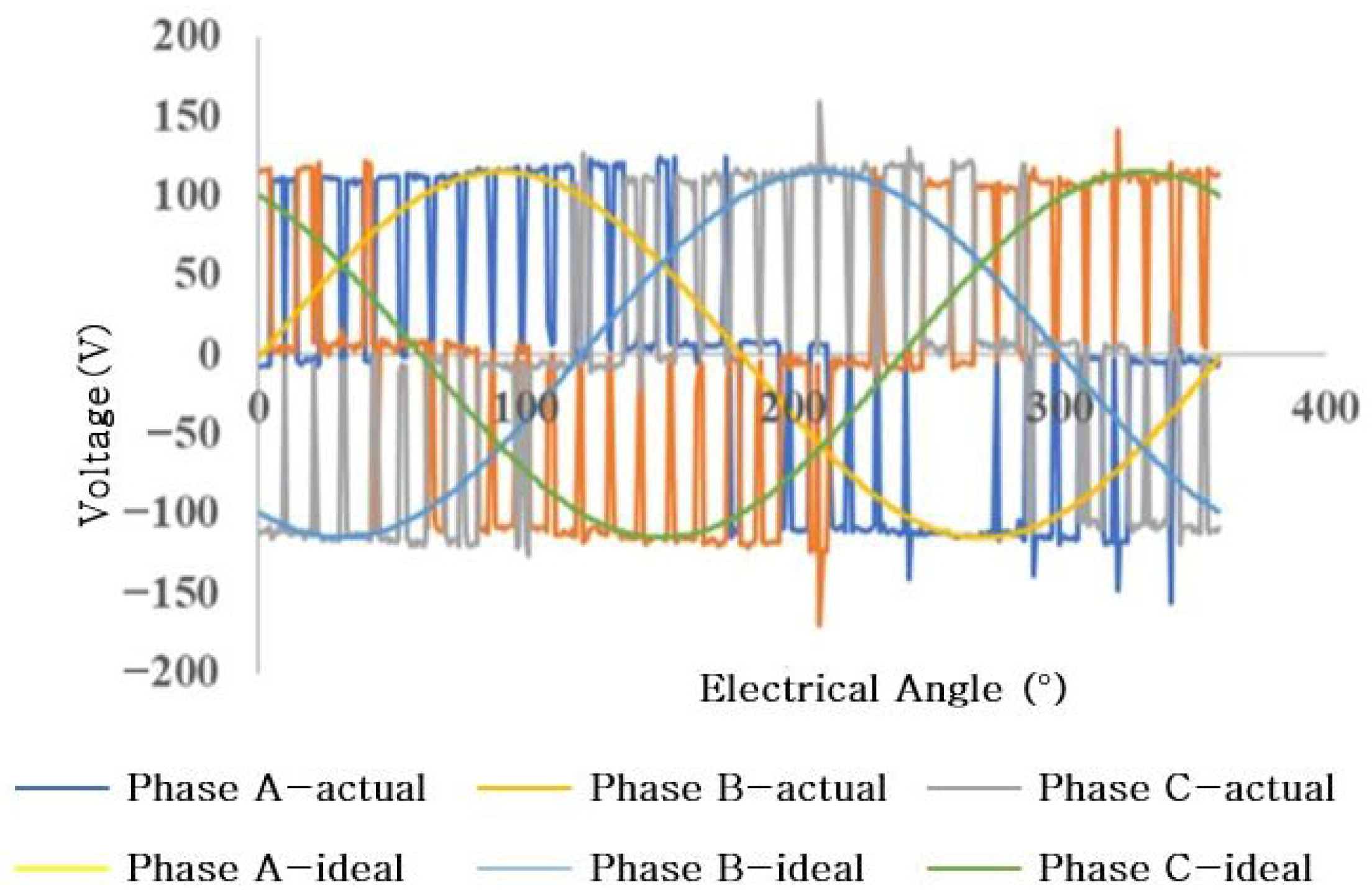
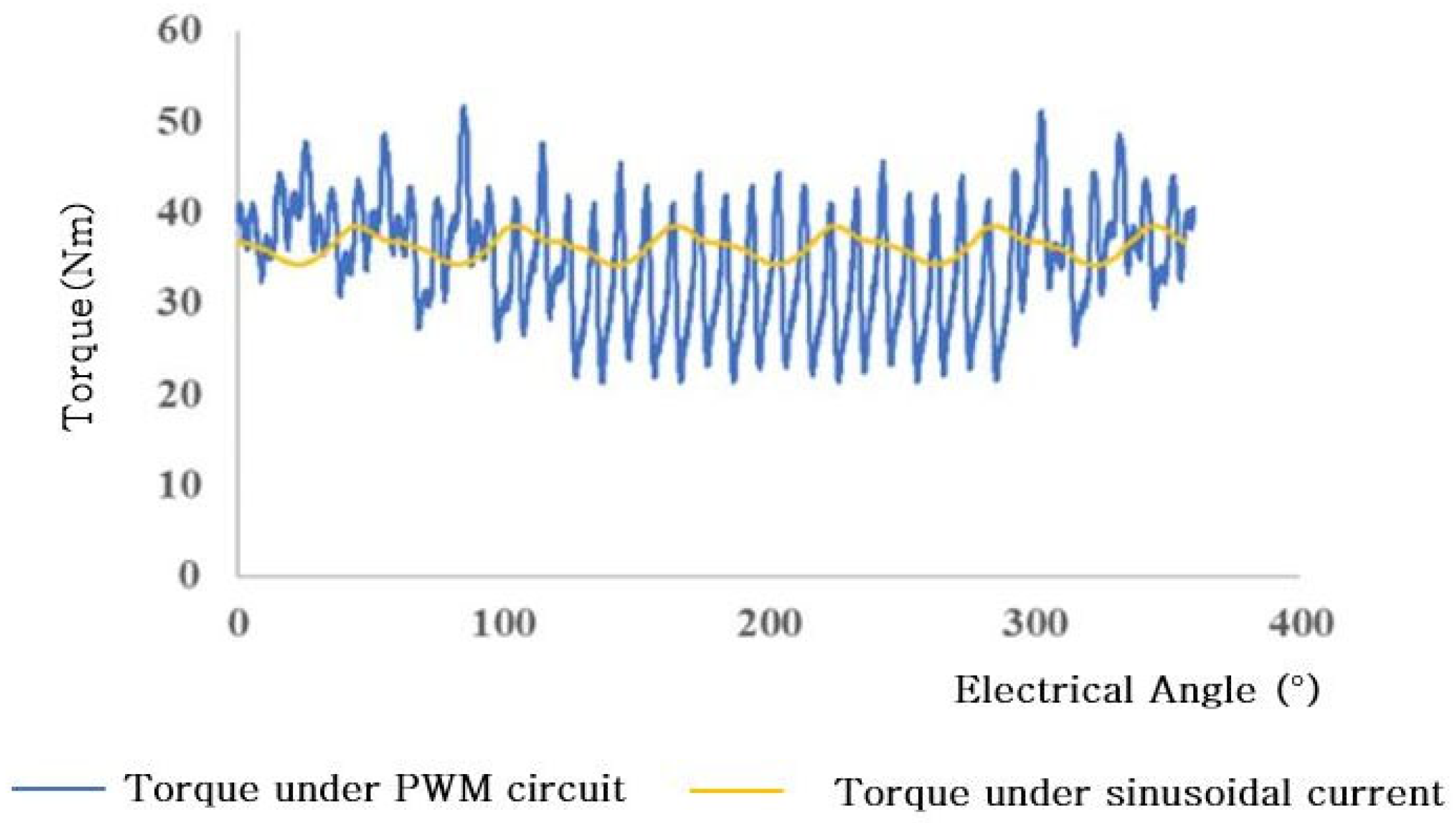
The control model algorithm adopts SVPWM control with a three-phase current closed-loop. As shown in Figure 1 and Figure 2, due to the large number of current and voltage harmonics caused by switching, there are considerable current harmonics in the three-phase current, with a harmonic current THD of 6.8%, and the three-phase current is not completely symmetrical and mutually symmetrical with respect to the origin; that is, there are even harmonics and a three-phase imbalance at the same time [16]. The three-phase voltage is a rectangular wave modulated based on the carrier wave, and it is accompanied by the spike voltage caused by the switching, and the THD of the harmonic voltage is 15.6%. Compared with sinusoidal armature magnetic fields, the voltage and current brought by PWM circuits are more likely to cause magnetic field distortion. As shown in Figure 3, the torque ripple is 3.1% under sinusoidal current excitation, while the torque ripple increases to 20.3% in a PWM circuit. In order to make it easier to display the harmonic current and voltage, the voltage and current are equivalent to the sum of each secondary current and voltage.
( v , i ) a = 1 k ( v , i ) k sin ( θ k + θ k 0 )
( v , i ) b = 1 k ( v , i ) k sin ( θ k + θ k 0 2 π / 3 )
( v , i ) c = ( v , i ) a ( v , i ) b
where ( v , i ) a , ( v , i ) b , ( v , i ) c is the three-phase real-time voltage and current; ( v , i ) k is the voltage and current amplitude of k phase, k = 1, 2…; θ k is the phase of k secondary phase current; and θ k 0 is the initial phase of k secondary phase current.

2.2. Distributed Nodes

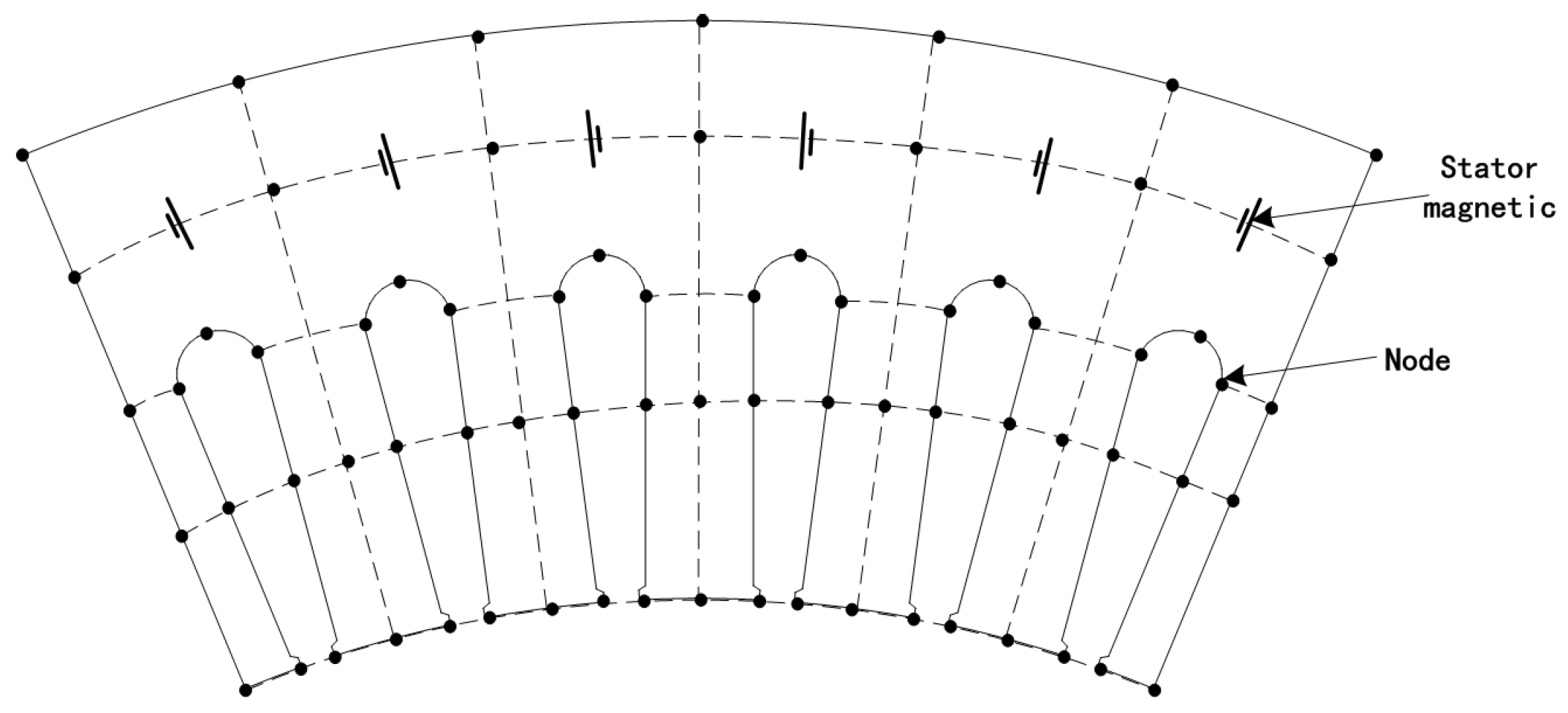
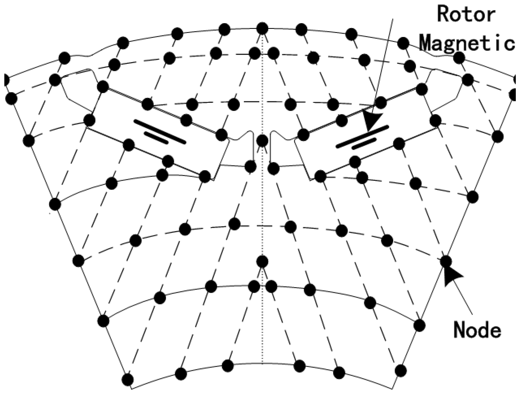
Converting the PMSM into a distributed mathematical model is key to optimizing the electromagnetic force waves under PWM control. The traditional distributed model forms key nodes according to the set grid [17], but in this study, the improved distributed model forms the key nodes according to the different material characteristics of the motor, and the permanent magnet synchronous motor mainly uses the air gap, stator, rotor, and magnet as the key nodes to form a distributed magnetic circuit between the nodes.
First of all, the motor is divided into two parts, stationary and rotary; the upper part of the middle of the air gap and the stator remain stationary, and the lower part of the middle of the air gap and the rotor remain relatively stationary. The middle layer is divided into key nodes at equal spacing, and the rotor surface and stator tooth surface are also divided into corresponding nodes at equal intervals [18]. Considering that the magnetic circuit is equivalent to the corresponding magnetic field lines, the magnetic field lines will not cross and attenuate [19]. Considering that the magnetic field lines of the magnet are perpendicular to the magnet, the upper and lower datum planes of the magnet are extended to the surface of the rotor and are divided into corresponding nodes. It should be noted that since the air magnetic resistance is much greater than the magnetic resistance of the iron core, the corresponding nodes of the stator inner circle are all equally divided on the tooth surface of the stator, and the corresponding nodes of the magnetic steel groove are all equally distributed on the magnetic steel groove profile.
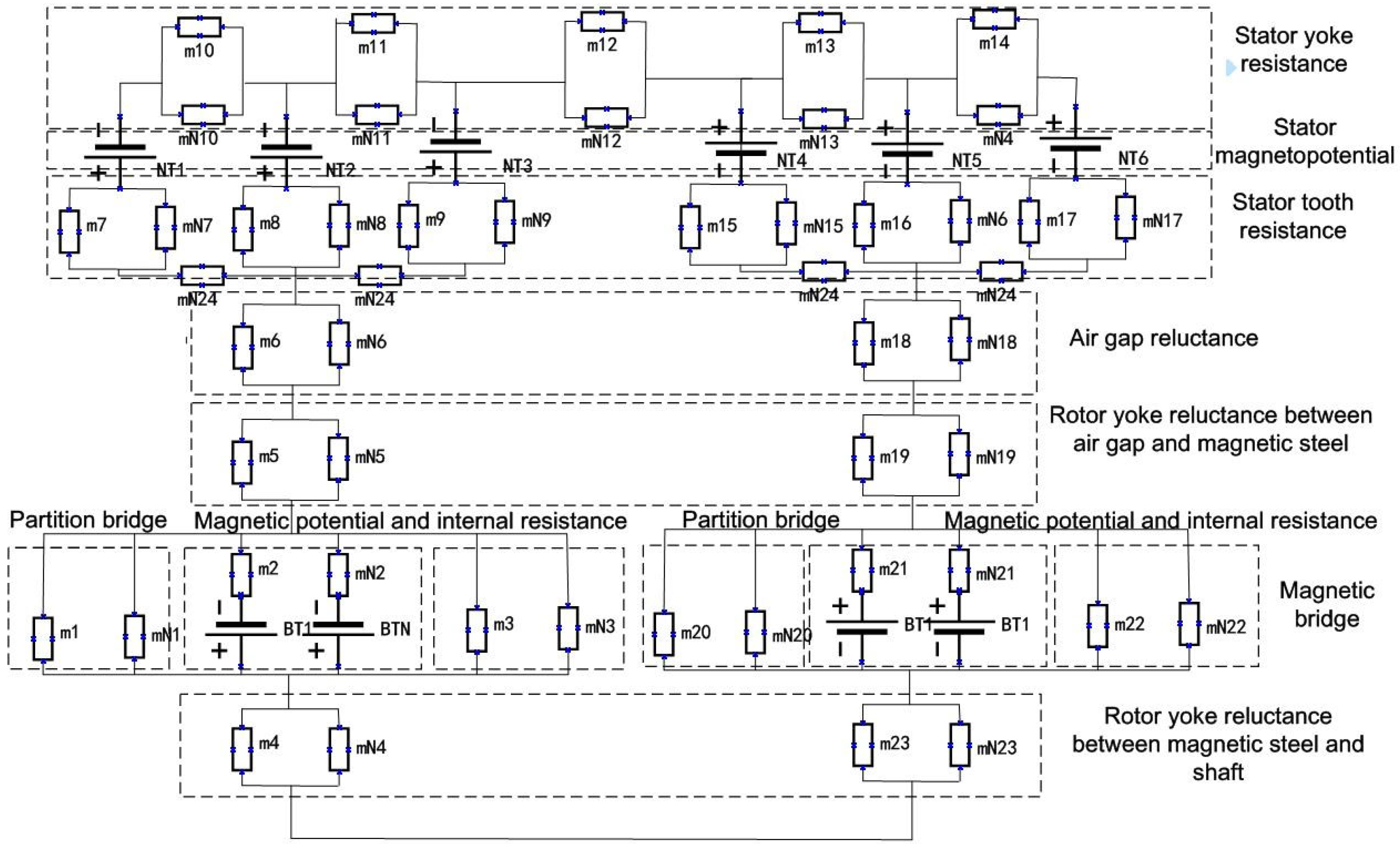
Secondly, following the principle of minimum magnetic resistance, the nodes are connected in a straight line to form a radial magnetic circuit. The methodology of initially considering only the radial magnetic path is consistent with the approach used in the majority of contemporary distributed flux-linkage models [20]. However, the radial magnetic circuit alone cannot take into account the influence of nonlinear parameters caused by the saturation of adjacent magnetic circuits [21]. In order to further increase the accuracy of the motor model, the adjacent magnetic circuits are connected tangentially, and the tangential magnetic circuits are added to enhance the mutual influence of the magnetic circuits [22]. When considering the operation of the motor, the magnetic field rotates in the center of a circle and is periodically symmetrical. The different radius arcs formed by the center of the circle form a tangential magnetic circuit in the stator, air gap and rotor, respectively. Correspondingly, the outer circle of the stator, the top of the stator tooth, the shoulder of the stator, the outer circle of the rotor, and the inner circle of the rotor are taken as the initial tangential magnetic field lines at the boundary of the key area, and in order to further optimize the adaptive grid, the unequal tangential magnetic field lines are filled in the middle of the initial tangential magnetic field lines according to the selection. In order to better illustrate the distributed nodes, only the key nodes are displayed, and the final distributed model is formed, as shown in Figure 4, Figure 5 and Figure 6. The stator magnetic potential is equivalent to being loaded between all the nodes of the adjacent stator teeth, while the rotor magnetic potential is equivalent to being loaded between all the nodes of the rotor magnet, where the stator magnetic potential F a , b , c and the magnet F m are, respectively,
F a , b , c = N i a , b , c
F m = H l = B S m
where N is the equivalent number of turns of the winding, H is the magnetic flux intensity, l is the equivalent thickness, B is the magnetic density, ∇m is the magnetic resistance, and S is the area.
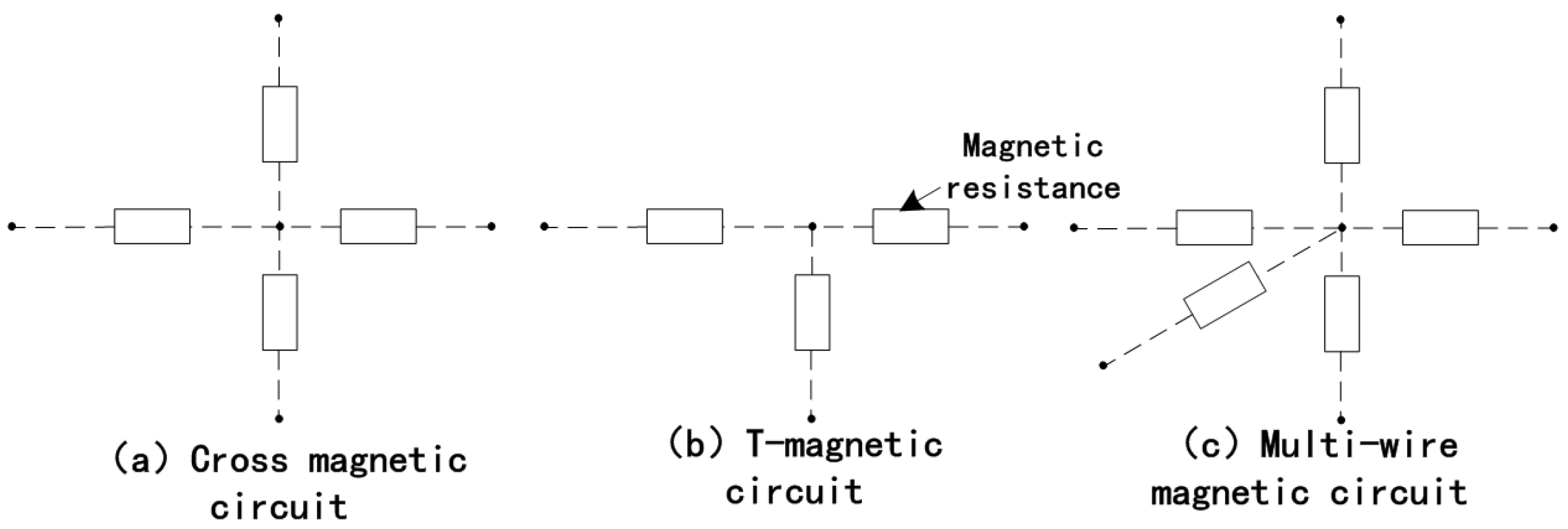
Again, the radial magnetic field lines and tangential magnetic field lines form a crossed magnetic circuit, and the magnetic circuit between nodes can be equivalent to the magnetic resistance calculated as R s t :
R s t = L s t S s t μ s t L a x
where L s t is the equivalent length, S s t is the equivalent area, S s t μ s t is the permeability, and L a x is the axial length. Most of the magnetic circuits are cross magnetic circuits, and in special areas, such as the outer circle of the stator and the inner circle of the rotor, the grid is a T-shaped magnetic circuit, and a multi-line magnetic circuit is formed at the top of some stator teeth, as shown in Figure 7.
It should be noted that the number of nodes is best taken as an integer multiple of the number of stator teeth; the more magnetic circuits, the higher the calculation accuracy and the higher the complexity of the model. In order to balance the complexity and the effectiveness of the model, nodes are set adjacent to different features to reduce the number of nodes and ensure the effectiveness of the model.
Finally, the distributed magnetic circuit model is formed as shown in Figure 8. Considering that when the motor is working, the stator and rotor have relative motion, in order to improve the efficiency of the adaptive grid calculation, when the air gap, the rotor node, and the magnetic circuit maintain a relatively stationary rotation, the air gap node is used as the benchmark to level the replacement and then convert it to the magnetic field change at different speeds; that is, there is no need to re-divide the rotor magnetic circuit, and the magnetic circuit is reduced by multiple constructions.
The number of selected nodes significantly impacts the computational accuracy. In principle, a higher number of nodes per unit length allows the distributed model to capture more magnetic flux, leading to a more accurate result. However, an excessive number of nodes adversely affects the computational speed. As illustrated in Figure 9a, a comparison between the distributed model with varying node densities and an FEM simulation reveals that the computational accuracy exceeds 99% when the number of nodes per unit length reaches eight or more. Therefore, a density of 8 nodes per unit length is adopted for the distributed model in this study. As illustrated in Figure 9b, when the air-gap thickness is below 0.6 mm, the calculation accuracy of the distributed model is relatively low (under 90%). This may be attributed to the strong influence of the stator teeth on the magnetic density in a small air gap, leading to a non-uniform distribution. When the air-gap thickness is above 0.7 mm, the model’s calculation accuracy is relatively high, exceeding 95%. As reported in previous research [10], the air-gap thickness in permanent magnet synchronous motors for automotive applications is typically designed to be greater than 0.7 mm. Therefore, the distributed model is well-suited for the analysis of such motors. Figure 9c shows that the model’s calculation accuracy is less sensitive to the rotor angle, consistently remaining above 95% for different angular positions. Similarly, as shown in Figure 9d, the model’s accuracy is also minimally affected by variations in the lamination thickness, staying above 95%. Although the magnetic permeability and iron loss vary significantly with different lamination thicknesses, the model’s accuracy is consequently less affected by these differences in material properties.

2.3. Distributed Flux Density

The air-gap magnetic flux density is a key determinant of motor performance [23]. Due to the influence of the magnetic circuit asymmetry and harmonic current brought by the PWM circuit, it can be equivalent to the magnetic dense coupling of different harmonics.
B i a , i b , θ , φ = 1 k F   sin ( α k + α k 0 )
where B is the magnetic density of the air gap, F is the magnetic potential, ∇ is the magnetic permeability, θ is the rotor angle, φ is the spatial angle of the magnetic density of the air gap, α k is the k magnetic density phase, and α k 0 is the k initial phase of the magnetic density.
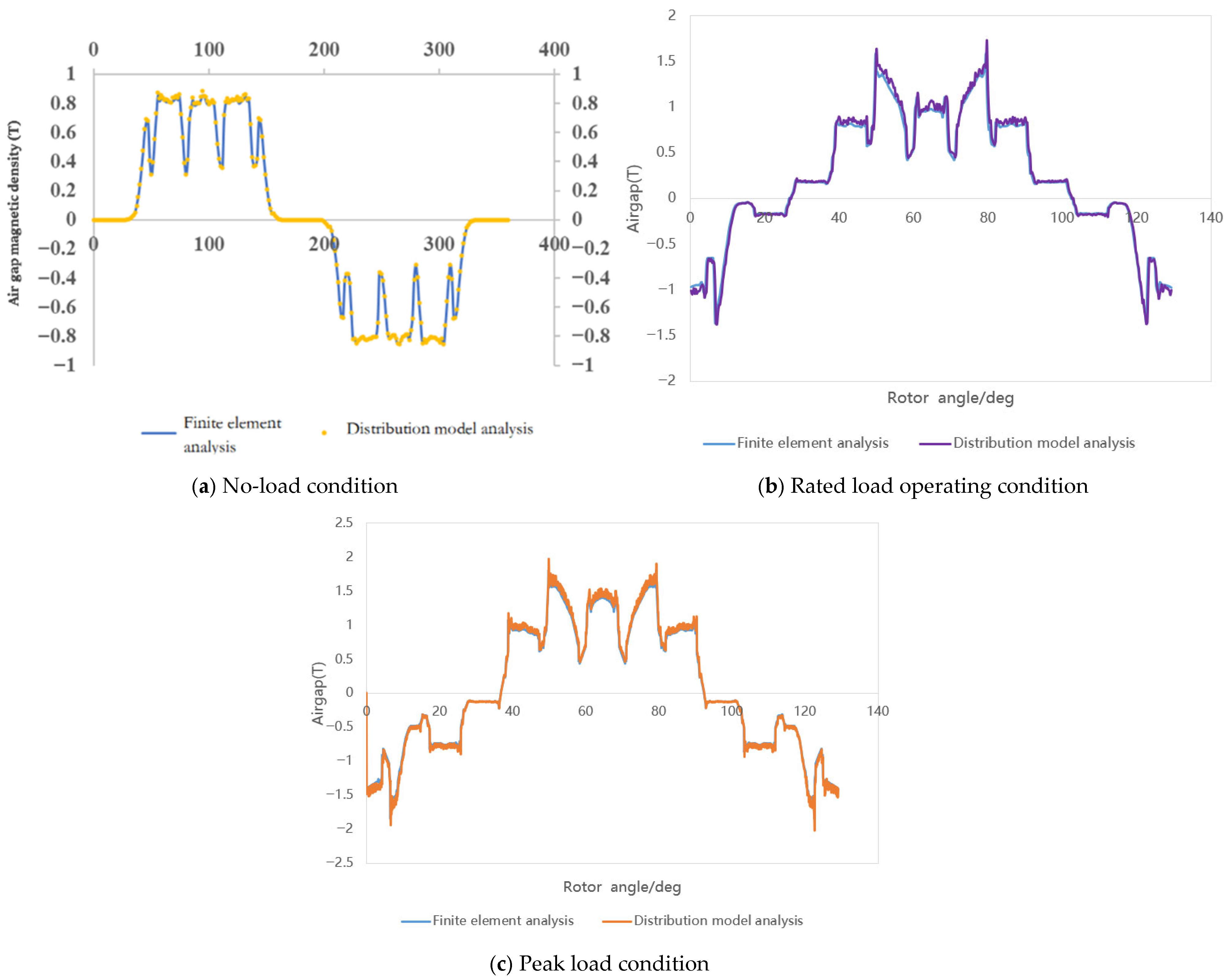
In order to verify the accuracy of the distributed model theory, the results of comparing the finite element analysis and the distributed model to calculate the magnetic density of the air gap are shown in Figure 10, and the calculation results are basically in good agreement. In the same way, the distributed model can largely restore the finite element analysis results by analyzing the magnetic density of the air gap under no-load and PWM circuits.
Furthermore, as shown in Table 2, the deviation in the calculated amplitude of the air-gap magnetic flux density between the two methods is small, remaining within 5% for all three operating conditions. However, the distributed model requires significantly less time, achieving a computational efficiency more than 15 times that of the FEM simulation. This is of significant importance for solving multi-objective optimization problems.
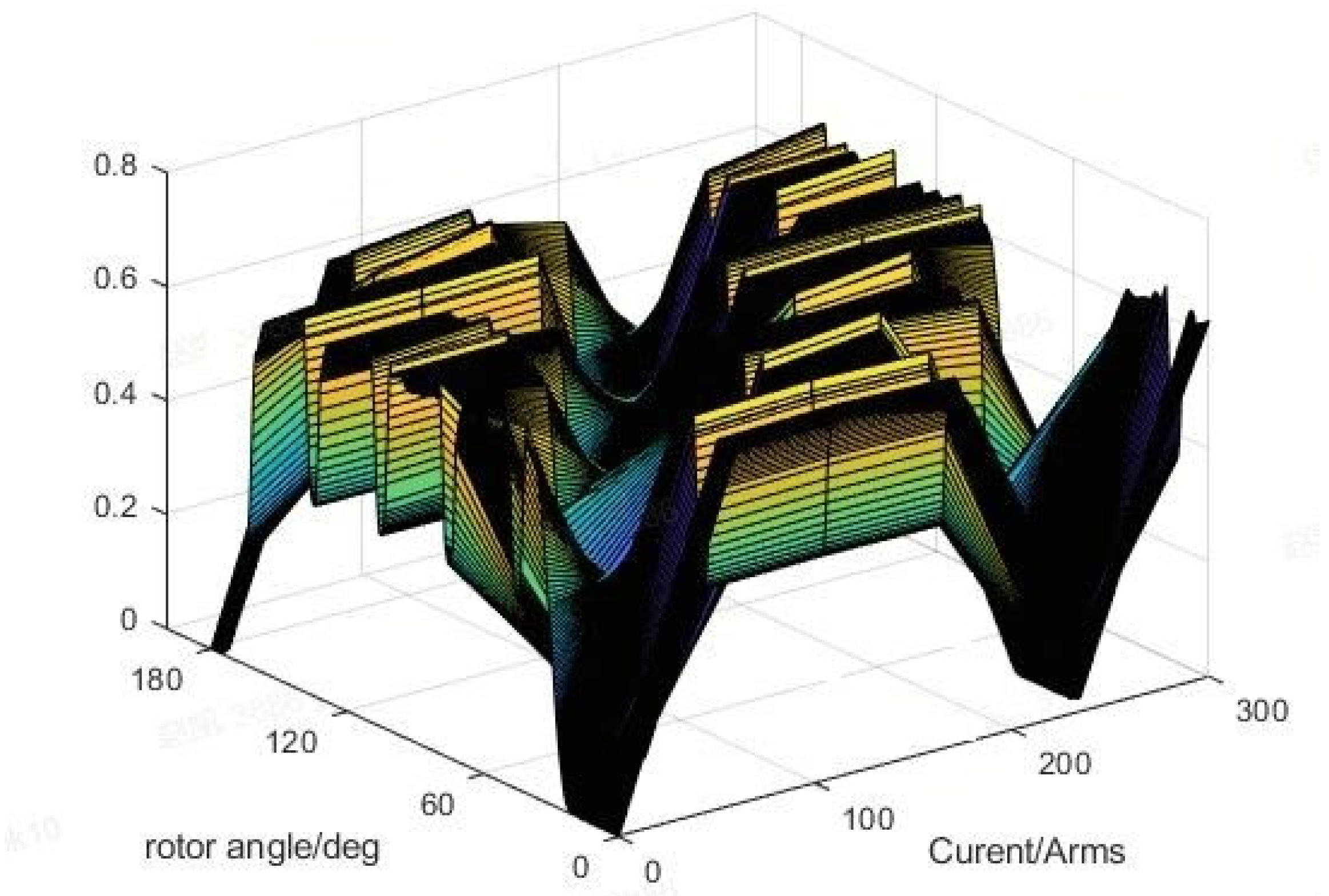
The magnetic density of the air gap is directly related to the stator magnetic potential, the rotor magnetic potential, the stator and rotor magnetoresistance, and the rotor position angle [24]. The spatial and temporal variation characteristics of the air-gap magnetic density with the change of the current and the rotation of the rotor position were calculated by the distributed node method. Figure 11 shows the change in magnetic density with the rotor angle and spatial angle under no load.

2.4. Distributed Electromagnetic Force Waves

The main characteristic of the motor is that the electromagnetic force wave is directly related to the magnetic density of the air gap, which is the direct source of vibration [25]. Electromagnetic force waves are caused by the alternating interaction between the stator magnetic field and the rotor magnetic field, and they are spatially symmetrically distributed [26], as shown in Equation (8).
F r = L 2 μ 0 ( B r i a , i b , θ , φ 2 B t i a , i b , θ , φ 2 )
where L is the integral of the air gap along the space, B r is the radial air gap magnetic density, and B t   is the tangential air gap magnetic density. The Fourier decomposition of a single radial force yields different spatial and temporal radial force orders, as shown in Figure 12.
Electromagnetic force waves excite harmonic responses through spatial and temporal order coupling and stator modes. The smaller the spatial order, the more likely it is to provoke resonance [27]. Among them, the 0th-order spatial mode has the largest vibration due to the lowest order, which is the main object of analysis.
A r d F r n 4
where A r d is the static displacement amplitude, F r is the radial electromagnetic force amplitude, n is the force wave number, and different time orders of the radial force in the full-speed section can be solved under the external circuit.

2.5. NVH Optimization

For the ideal permanent magnet synchronous motor, due to the periodic symmetry of the motor in space, there are generally 8-octave major orders, such as 8, 24, 48, and 96 orders, and the other 8-octave harmonic energy is small, and it is difficult to be excited to vibrate noise. However, the stator and rotor magnetic circuit structure of a permanent magnet motor is complex, and the current harmonics are introduced into the control circuit, resulting in the magnetic field containing pronounced harmonic components, such as 40, 56, 64, etc., which cause large electromagnetic force waves, which pose great challenges to the vibration, noise, and control accuracy. Optimizing the current harmonics from controller softening and hardware will bring about a decrease in power and efficiency, which can be optimized by the motor itself. According to the Fourier decomposition of electromagnetic force waves under risk conditions, the specific order harmonics that cause the risk order and risk speed are analyzed, and the harmonics of the specific orders 11, 13, 15, and 17 are the main harmonic factors that cause the 8-octave order. As shown in Equation (10), the corresponding time order under the 8th order of the air gap magnetic dense space is mainly controlled to optimize the specific order.
F r m = min ( m = 2,3 . . . B r m i a , i b , θ , φ 2 B t m i a , i b , θ , φ 2 )
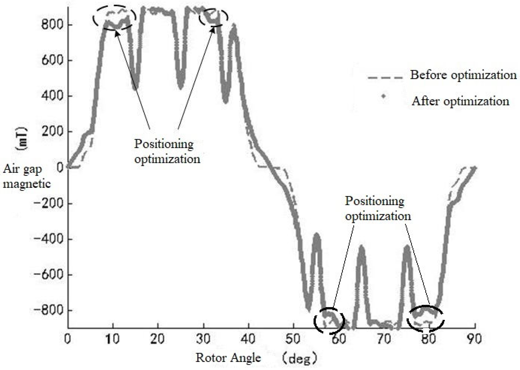
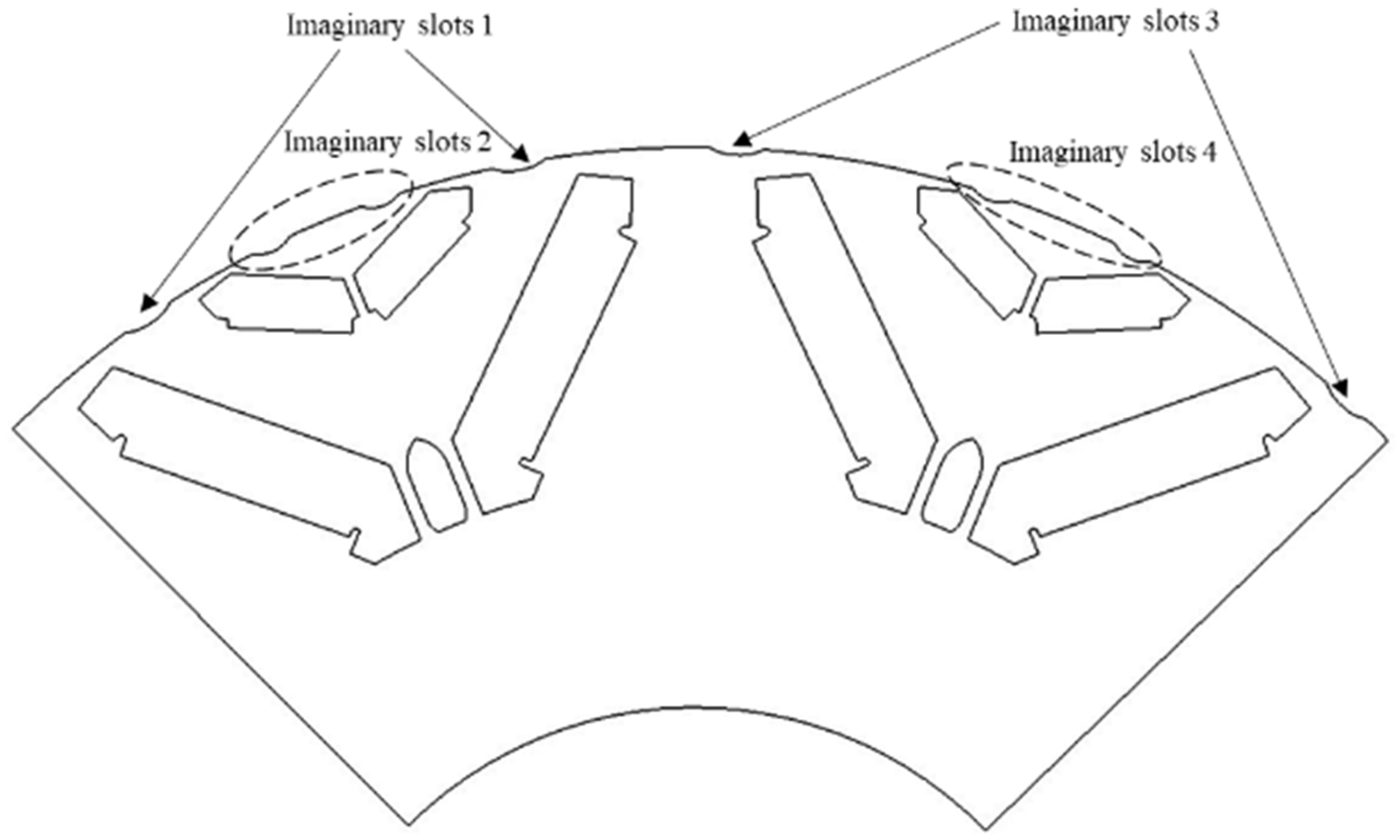
However, the air-gap magnetic field is coupled with the stator magnetic field and the rotor magnetic field, resulting in the inconsistent realization of electromagnetic force waves with different speeds and torques, which poses great challenges to the optimization of electromagnetic force waves. Combined with the distributed motor model, it can quickly solve the variation of electromagnetic force waves in different times and spaces based on the full speed and full working conditions. At the same time, it can quickly locate the changes in the shape and size of the position to bring about the changes in the electromagnetic force wave. Firstly, the air-gap thickness of the virtual groove and the magnetic gap magnetic density caused by the magnetic arc and the included angle of the magnet are calculated, and the multi-objective optimization solution of the torque power, and it is established that the position of the virtual groove has a great influence on the electromagnetic force wave, and at the same time, it has little influence on the torque power, which is the most suitable optimization parameter. However, a single fixed virtual groove cannot reduce the 40, 56, and 64 multi-order electromagnetic force waves at the same time, nor can it weaken the electromagnetic force waves at low speed or high speed and low torque or high torque at the same time. The optimization described above is designated as optimization mode 1 of the distributed model. To enhance the model’s computational efficiency, a second approach, optimization mode 2, is introduced, as depicted in Figure 13. In this mode, the distributed model is used to perform a Fourier decomposition of the air-gap magnetic density. After removing the 11th, 13th, 15th, and 17th harmonics, which are critical contributors to specific modal orders, the air-gap magnetic density is reconstructed. A comparison of the magnetic density waveforms before and after this reconstruction is presented in Figure 14. From Figure 14, significant discrepancies are identified at specific locations in the air-gap magnetic density, corresponding to rotor positions at 11 deg, 36 deg, 53 deg, and 83 deg. Consequently, virtual slots are introduced at these four locations on the rotor for optimization, initially forming virtual slot 1 and virtual slot 3, as shown in Figure 15. These initial slots are then further optimized and adjusted using mode 1, resulting in the final configuration of virtual slot 2 and virtual slot 4. Furthermore, it is noted that the motor efficiency can be affected during the harmonic optimization process [13], and its impact should be constrained to within 0.1%. Therefore, to achieve the best overall optimization results, a two-stage strategy is employed: mode 2 is first used for rapid NVH harmonic analysis, followed by mode 1 for a multi-objective optimization that includes the motor efficiency as a key performance indicator. Therefore, the combined asymmetric virtual groove is proposed, which mainly optimizes different orders, adapts to the electromagnetic force wave under different working conditions through different virtual groove positions, and finally, locks the position of the virtual groove on the rotor surface through multi-objective optimization, as shown in Figure 15.
It can be seen from Table 3 that compared with a single virtual slot, the combined asymmetric imaginary slot can significantly reduce the magnetic density of the no-load air gap by the 5th/7th, 11th/13th and 15th/17th harmonics. Previous research [9] analyzed the harmonic content of a 48-slot 8-pole motor and concluded that the dominant harmonics were the 5th, 7th, 11th, 13th, 15th, and 17th, among which the content of the 5th/7th harmonic was the highest. The 11th/13th harmonics were the first-order tooth harmonics caused by stator slotting, and the 15th/17th harmonics were the second-order tooth harmonics caused by stator slotting. As can be seen from Table 4, the 11th/13th harmonics form the 40th and 56th time–frequencies of the 8th force wave, and the 15th/17th harmonics form the 64th time–frequency of the 8th force wave. Compared with a single virtual slot, which cannot take into account the harmonic energy at multiple orders and speeds, the combination of asymmetric virtual slots can reduce the main order and the 8-octave auxiliary order, and at the same time, it can take into account the weakening of harmonic energy at 4500 rpm peak load and 8500 rpm peak power. Furthermore, as shown in Table 3, the reduction of the 40th, 56th, and 64th auxiliary orders is more significant for the 6-pole, 54-slot motor compared to the 8-pole, 48-slot motor. This is likely because the tooth flux density in the 54-slot motor is higher, making the weakening effect of the combined asymmetrical dummy slots on these auxiliary orders more pronounced.

3. Experimental Validation

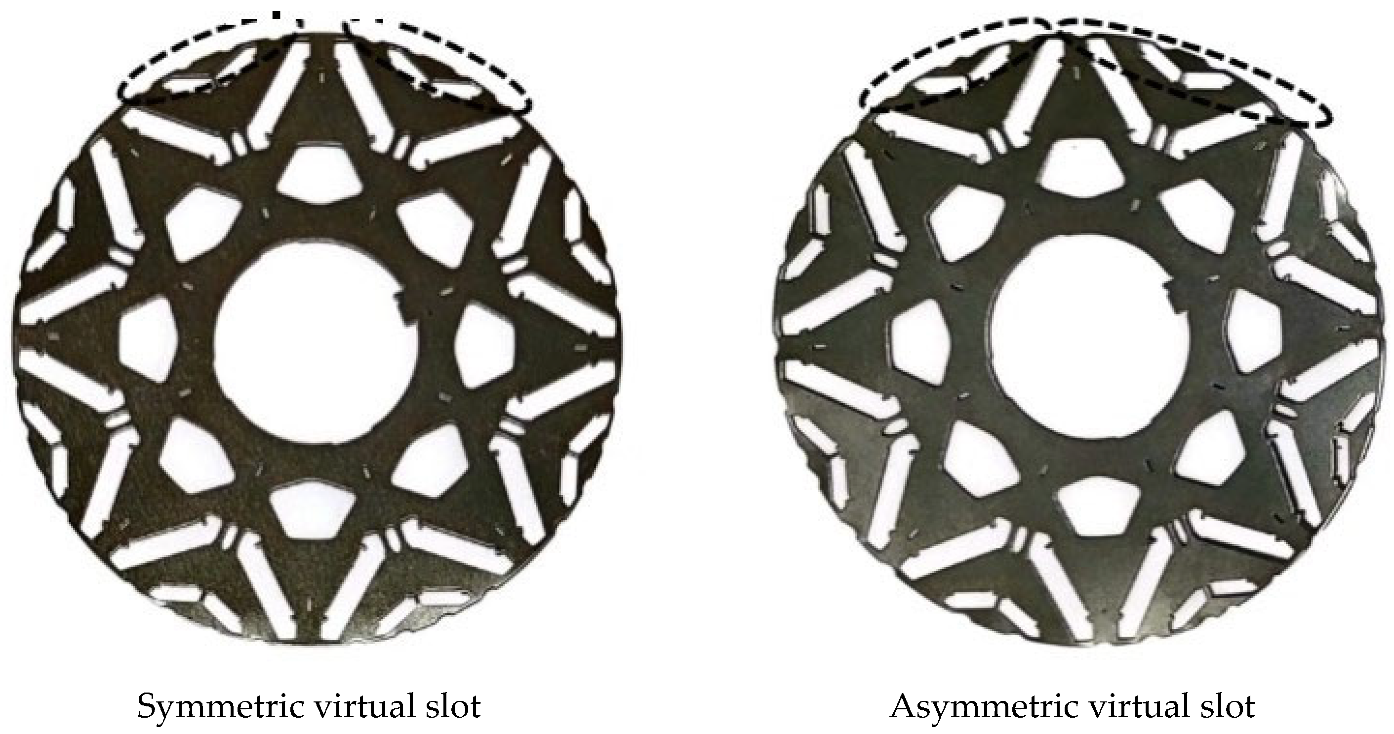
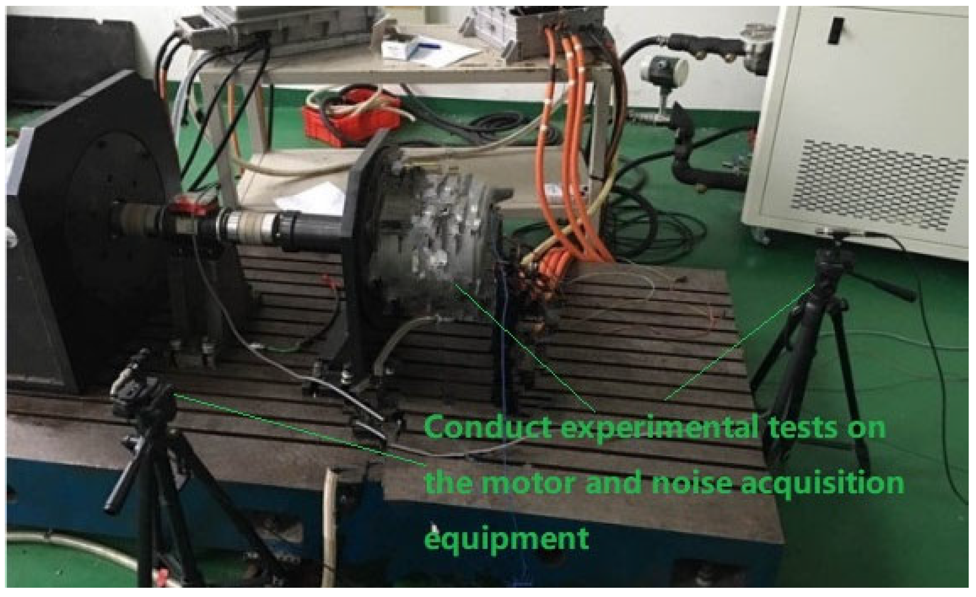
Finally, the asymmetric virtual groove and a single symmetrical virtual groove were combined to make the actual object, as shown in Figure 16, and the prototype before and after optimization was compared on the same bench based on the same conditions, as shown in Figure 17.
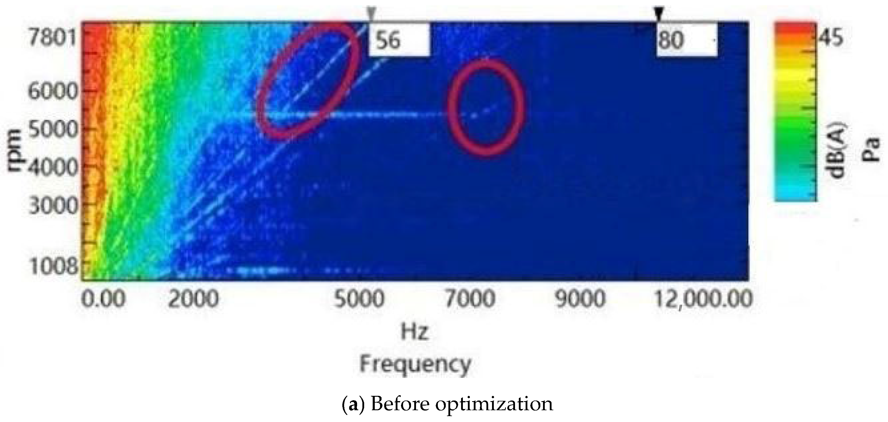
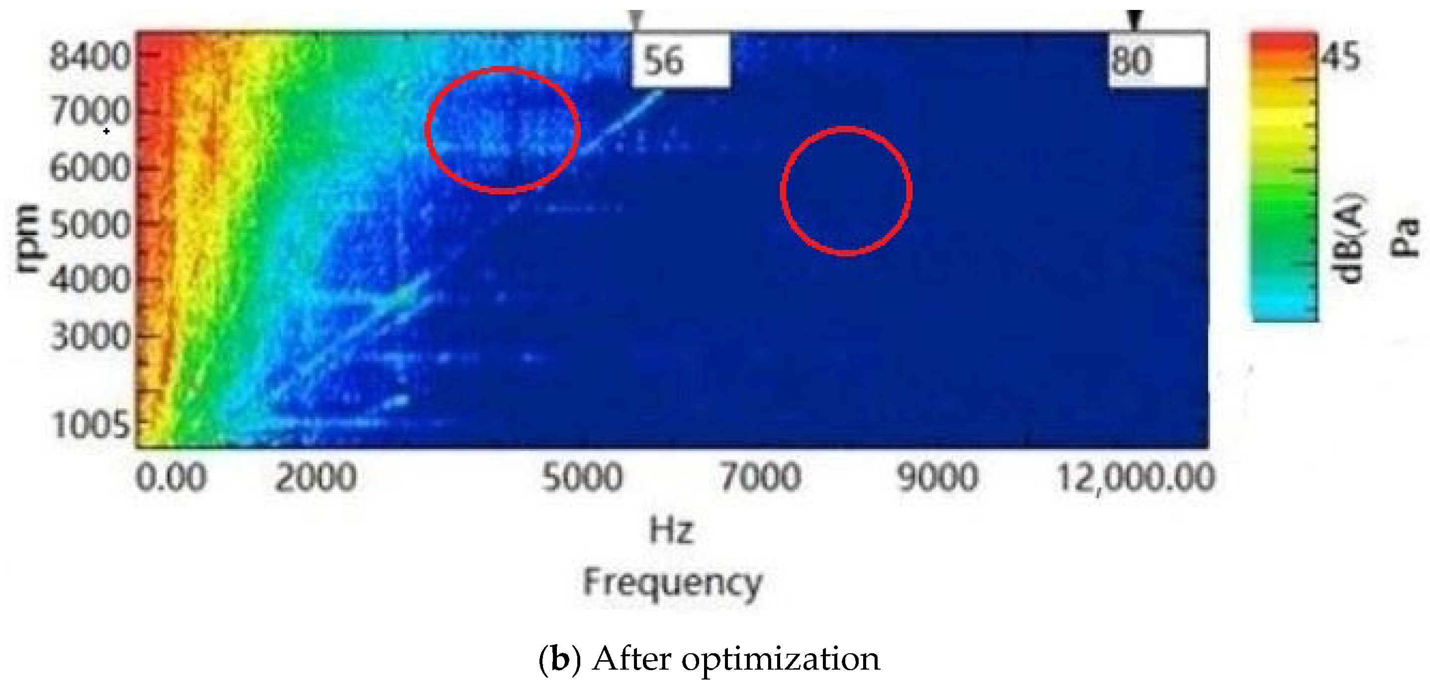
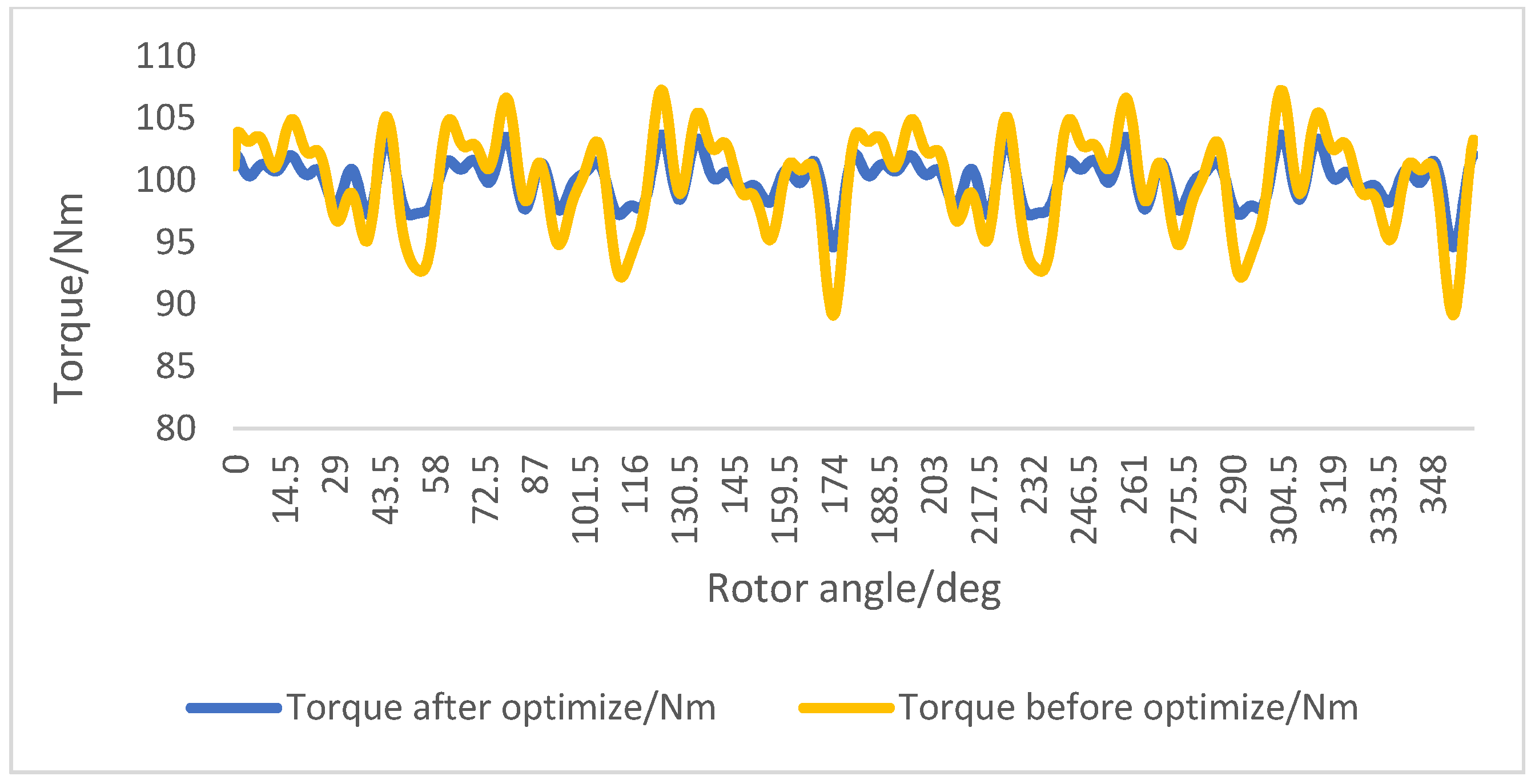
The NVH performance of the rotor before and after improvement is shown in Figure 18. The noise order color map in the figure was generated from noise signals acquired during tests on a semi-anechoic chamber test rig. The data acquisition system used was an LMS SCADAS Mobile, and the analysis was performed with LMS Test.Lab (2019 version). The upper figure displays the color map before the improvement of the rotor groove, while the lower figure shows the color map after the improvement. It can be observed that after the improvement of the rotor groove, significant improvements are evident in the 56th-order and 80th-order time–frequency components. Based on the above analysis, the 56th-order and 80th-order time–frequency components correspond to the 8th-order force wave. The noise levels of both orders were reduced by more than 5 dB. Therefore, the asymmetric virtual groove demonstrates a notable improvement in addressing the NVH issues associated with the spatial eighth-order force wave. Additionally, as shown in Figure 19, before optimization, for a nominal torque of 100 Nm, the peak and trough were 105 Nm and 95 Nm, respectively, resulting in a 10% torque ripple. After optimization, these values became 102 Nm and 97 Nm, which correspond to a 5% torque ripple. Thus, the optimization with asymmetrical dummy slots reduced the torque ripple by 5 percentage points. As summarized in Table 5, the total sound pressure level of the motor noise was reduced by 10 dB, and the torque ripple decreased by 5%. These results validate the optimization of the NVH and torque ripple achieved using the distributed model, from which an asymmetric virtual slot scheme was developed. The experiments were conducted multiple times on the test bench, confirming a measurement repeatability of within 2%. The experimental results thus demonstrate the effectiveness of the proposed scheme.

4. Conclusions

In this paper, a distributed mathematical model considering the control circuit is proposed, and the electromagnetic force wave weakening of the motor is quickly completed by analyzing the spatial and temporal changes in the air-gap magnetic density with the rotor angle and the current, and by accurately locating and optimizing the risk order of the electromagnetic force wave.
Firstly, a nonlinear motor model is built, which is equivalent to a distribution node and a magnetic circuit.
Secondly, the magnetic density of the air gap is solved with the current and the rotor position angle in space and time, and the electromagnetic force wave is distributed for the calculation.
The risk order and risk speed at the full speed of the control circuit are analyzed, the sensitive parameters are located, and the topology is optimized accordingly.
Finally, the accuracy of the theory is verified by the prototype.
The proposed model achieves an accuracy of over 95% in predicting key NVH indicators compared to FEM, while improving the computational speed by more than 12-fold.
By leveraging this distributed model to optimize the parameters of the rotor’s asymmetrical dummy slots, the critical order noise of the target motor was successfully reduced by more than 5 dB, and the torque ripple was decreased by over 5 percentage points.
This study has certain limitations. The current model is linear and does not account for complex physical phenomena such as material nonlinearity and saturation effects. Furthermore, this work focuses on a single NVH objective, whereas practical engineering often requires a trade-off among multiple objectives, including the NVH, efficiency, and cost.
Future work will leverage the validated model framework to systematically investigate and compare the quantitative effects of different advanced PWM strategies on motor NVH, enabling targeted optimization. Subsequent research will also focus on the trade-off between motor efficiency and harmonic suppression, incorporating an analysis of magnetic material quality. This will be pursued as a future extension of this study.

Author Contributions

Conceptualization, J.L.; methodology, writing—original draft preparation, K.Z.; formal analysis and investigation, K.Z. and Z.J.; writing—review and editing, supervision, J.L. All authors have read and agreed to the published version of the manuscript.

Funding

This research was funded by the HRG-QR-2019JSFW-01 Technical Testing Service Contract (19H01503).

Data Availability Statement

The original contributions presented in this study are included in the article. Further inquiries can be directed to the corresponding author.

Conflicts of Interest

The authors declare no conflicts of interest. The funders played no role in the design of the study, in the collection, analyses, or interpretation of data, in the writing of the manuscript, or in the decision to publish the results. The authors declare that the research was conducted in the absence of any commercial or financial relationships that could be construed as a potential conflicts of interest.

Abbreviations

The following abbreviations are used in this manuscript:
NVHNoise, vibration and harshness
PWMPulse width modulation

References

  1. Du, J.; Ouyang, M.; Wu, X.; Meng, X.; Li, J.; Li, F.; Song, Z. Technological direction prediction for battery electric bus under influence of China’s new subsidy scheme. J. Clean. Prod. 2019, 222, 267–279. [Google Scholar] [CrossRef]
  2. Zhu, Y.; Bai, F.; Sun, J. Multi-objective optimization algorithm for optimizing NVH performance of electric vehicle permanent agnet synchronous motors. J. Power Electron. 2022, 22, 2039–2047. [Google Scholar] [CrossRef]
  3. Parpinel, A.; Bouvet, P.; Dupont, J.B. NVH multiobjective and robust optimization of electric motor design, including power losses. In Proceedings of the INTER-NOISE and NOISE-CON Congress and Conference Proceedings, INTER-NOISE24, Nantes, France, 25–29 August 2024; Volume 270, pp. 7073–7083. [Google Scholar] [CrossRef]
  4. Li, H.; Xu, P.; Cao, C.; Hu, D.; Yan, X.; Song, Z. Acoustic simulation of the electric vehicle motor. J. Phys. Conf. Ser. 2021, 2095, 012031. [Google Scholar] [CrossRef]
  5. Arafat, A.; Choi, S. Active current harmonic suppression for torque ripple minimization at open phase faults in a five-phase PMa-SynRM. IEEE Trans. Ind. Electron. 2019, 66, 922–931. [Google Scholar] [CrossRef]
  6. Lee, Y.K.; Bang, T.K.; Jo, S.T.; Lee, H.K.; Kim, Y.J.; Lee, S.H.; Kim, M.S.; Choi, J.Y. A study on the shaft stability and prediction of electromagnetic and NVH characteristics of permanent magnet synchronous machine according to the different pole/slot combination. AIP Adv. 2023, 13, 025121. [Google Scholar] [CrossRef]
  7. Xu, J.; Zhang, L.; Meng, D.; Su, H. Simulation, verification and optimization design of electromagnetic vibration and noise of permanent magnet synchronous motor for vehicle. Energies 2022, 15, 5808. [Google Scholar] [CrossRef]
  8. Song, T.F.; Liu, H.J.; Bu, B.B.; Zhang, Z.Y. Rapid calculation and optimization of vibration and noise of permanent-magnet synchronous motors for EVs based on equivalent structural network. Machines 2022, 10, 281. [Google Scholar] [CrossRef]
  9. Ou, L.Z.; Wang, X.F.; Xiong, F.; Ye, C.Y. Reduction of torque ripple in a wound-rotor brushless doubly-fed machine by using the tooth notching. IET Electr. Power Appl. 2018, 12, 635–642. [Google Scholar] [CrossRef]
  10. Mollaee, S.; Budgett, D.M.; Taberner, A.J.; Nielsen, P.M.F. Hyperelastic constitutive model parameters identification using optical-based techniques and hybrid optimisation. Int. J. Mech. Mater. Des. 2023, 20, 233–249. [Google Scholar] [CrossRef]
  11. Zhao, J.; Liu, G.; Huo, S.; Wang, G.; Sun, C.; Li, Z. A Node-Based Smoothed Finite Element Method (NS-FEM) for free and forced vibration analysis of Three-Dimensional (3D) structures. Int. J. Comput. Methods 2024, 22, 2342010. [Google Scholar] [CrossRef]
  12. Jun, S.B.; Kim, C.H.; Cha, J.; Lee, J.H.; Kim, Y.J.; Jung, S.Y. A novel method for establishing an efficiency map of IPMSMs for EV propulsion based on the finite-element method and a neural network. Electronics 2021, 10, 1049. [Google Scholar] [CrossRef]
  13. Soresini, F.; Barri, D.; Ballo, F.; Gobbi, M.; Mastinu, G. Noise and vibration modeling of Permanent Magnet Synchronous Motors: A review. IEEE Trans. Transp. Electrif. 2024, 10, 8728–8745. [Google Scholar] [CrossRef]
  14. Hotma, L.; Purnama, H.; Purnomo, E.D.; Arifin; Nasril; Azka, M.; Sulistiyo, W.; Perkasa, M.; Marpaung, F.; Nugroho, E.A. Materials selection for low-cost manufacturing of electric motorcycle platform by using Finite Element Method (FEM) evaluation and Digital Logic Method (DLM). AIP Conf. Proc. 2024, 3069, 020030. [Google Scholar] [CrossRef]
  15. Zhou, Y.; Li, Z.; Wang, C.; Wang, J. Design of a distributed hybrid model predictive controller based on long short-term memory networks model for hub-motor electric vehicle with air suspension. Proc. Inst. Mech. Eng. 2025. [Google Scholar] [CrossRef]
  16. Liu, X.; Chen, H.; Zhao, J.; Belahcen, A. Research on the performances and parameters of interior PMSM used for electric vehicles. IEEE Trans. Ind. Electron. 2016, 63, 3533–3545. [Google Scholar] [CrossRef]
  17. Lu, Y.; Li, J.; Qu, R.H.; Ye, D.L.; Lu, H.X.; Sun, J.B.; Ge, M.; Xu, H.W. Electromagnetie force and vibration analysis of permanent-magnet-assisted synchronous reluctance machines. IEEE Trans. Ind. Appl. 2018, 54, 4246–4256. [Google Scholar] [CrossRef]
  18. Guo, F.; Chu, Q.; Li, C.; Meng, T. Research on influence of motor parameters on the Negative-Salient Permanent Magnet Synchronous Motor. CES Trans. Electr. Mach. Syst. 2022, 6, 77–86. [Google Scholar] [CrossRef]
  19. Li, C.; Wang, X.; Liu, F.; Ren, J.; Xing, Z.; Gu, X. Analysis of permanent magnet-assisted synchronous reluctance motor based on equivalent reluctance network model. CES Trans. Electr. Mach. Syst. 2022, 6, 135–144. [Google Scholar] [CrossRef]
  20. Peng, M.D.; Zhang, G.Y.; He, Z.C.; Huang, Y.Y.; Gao, H. Motor magnetic field analysis using the alpha Finite Element Method (αFEM). Int. J. Comput. Methods 2025. [Google Scholar] [CrossRef]
  21. Levent, A.H.; Lordoglu, A.; Aydeniz, M.G. Design and optimization of permanent magnet synchronous motor for electric vehicle applications. In Proceedings of the 2020 2nd Global Power, Energy and Communication Conference (GPECOM), Izmir, Turkey, 20–23 October 2020; pp. 148–151. [Google Scholar] [CrossRef]
  22. Pierre-Daniel, P.; Yin, X.; Fang, Y.T. Slotted Permanent-Magnet Machines: General analytical model of magnetic fields, torque, eddy currents, and Permanent-Magnet power losses including the diffusion effect. IEEE Trans. Magn. 2016, 52, 1–13. [Google Scholar] [CrossRef]
  23. Ma, C.; An, Y.; Zhao, H.; Guo, S.; Yin, X.; Lu, H. 3-D analytical model and direct measurement method of Ultra-Thin Open-Circuit Air-Gap field of interior permanent magnet synchronous motor with multi-segmented skew poles and multi-layered flat wire windings for electric vehicle. IEEE Trans. Energy Convers. 2020, 35, 1316–1326. [Google Scholar] [CrossRef]
  24. Tong, W.; Dai, S.; Wu, S.; Tang, R. Performance comparison between an amorphous metal PMSM and a silicon steel PMSM. IEEE Trans. Magn. 2019, 55, 1–5. [Google Scholar] [CrossRef]
  25. Jin, H.L.; Kim, D.W.; Song, J.Y.; Jung, S.Y.; Kim, Y.J. Design of 100 kW propulsion motor for electric conversion vehicle based on vehicle driving performance simulation. In Proceedings of the 2016 IEEE Transportation Electrification Conference and Expo, Asia-Pacific (ITEC Asia-Pacific), Busan, Republic of Korea, 1–4 June 2016; pp. 412–416. [Google Scholar] [CrossRef]
  26. Verdyck, D.; Belmans, R.J.M. An acoustic model for a permanent magnet machine: Modal shapes and magnetic forces. IEEE Trans. Ind. Appl. 1994, 30, 1625–1631. [Google Scholar] [CrossRef]
  27. Xing, Z.Z.; Wang, X.H.; Zhao, W.L. Research on weakening measure of radial electromagnetic force waves in permanent magnet synchronous motors by inserting auxiliary slots. IET Electr. Power Appl. 2020, 14, 1381–1395. [Google Scholar] [CrossRef]
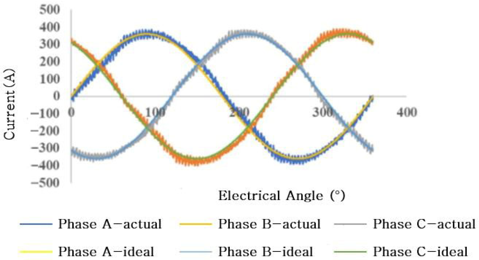
Figure 1. Current waveform. Three-phase current waveform under PWM control, showing distortion and asymmetry compared with the ideal sinusoidal case.
Energies 18 05395 g001
Figure 2. Voltage waveform. Three-phase voltage waveform generated by the PWM circuit, illustrating rectangular modulation and spike voltages from switching events.
Energies 18 05395 g002
Figure 3. Torque waveform. Torque waveform comparison: torque ripple of 3.1% under sinusoidal excitation versus 20.3% under PWM control.
Energies 18 05395 g003
Figure 4. Stator distribution model.
Energies 18 05395 g004
Figure 5. Rotor distribution model.
Energies 18 05395 g005
Figure 6. Air gap model.
Energies 18 05395 g006
Figure 7. Magnetic circuit model.
Energies 18 05395 g007
Figure 8. Distributed magnetic circuit model.
Energies 18 05395 g008
Figure 9. (a) The influence of the number of nodes on calculation accuracy. (b) The influence of the airgap thickness on calculation accuracy. (c) The influence of the rotor angle on calculation accuracy. (d) The influence of the thickness of the core sheet on calculation accuracy.
Energies 18 05395 g009
Figure 10. Magnetic density of the air gap under the finite element and distributed model.
Energies 18 05395 g010
Figure 11. Spatial and temporal variation of magnetic density.
Energies 18 05395 g011
Figure 12. Fourier decomposition of the spatiotemporal variation of magnetic density.
Energies 18 05395 g012
Figure 13. Air-gap magnetic density harmonic analysis.
Energies 18 05395 g013
Figure 14. Air-gap magnetic density wave comparison.
Energies 18 05395 g014
Figure 15. Asymmetric multi-combination imaginary slots.
Energies 18 05395 g015
Figure 16. Motor rotor punching with different virtual slots.
Energies 18 05395 g016
Figure 17. Motor NVH test platform.
Energies 18 05395 g017
Figure 18. NVH test results of the single motor before and after rotor groove improvement.
Energies 18 05395 g018aEnergies 18 05395 g018b
Figure 19. Comparison of the peak torque ripple before and after asymmetric virtual slot optimization.
Energies 18 05395 g019
Table 1. Main motor parameters.
Technical IndicatorsMatch Results
Maximum Torque (Nm)100
Rated Torque (Nm)50
Peak Power (kW)30
Rated Power (kW)15
Maximum Speed (rpm)10,000
Rated Speed (rpm)3000
Table 2. Comparison of the computation time and amplitude deviation of the two methods.
Time of Simulation (s)Time of Distributed Model (s)The Amplitude Deviation of the Two Methods (T)
No load180100.04
Rated load200120.06
Peak load200120.1
Table 3. Comparison of asymmetric multi-combination virtual groove performance.
OrderSingle Symmetrical Imaginary SlotCombined Asymmetrical Imaginary SlotsPolar Groove Fit
The no-load air gap magnetically dense5/73.2%/2.2%1.6%/1.7%8P48
11/131.6%/1.5%0.5%/0.4%8P48
15/171.0%/0.8%0.3%/0.4%8P48
23/250.6%/0.4%0.8%/0.7%8P48
The 4500 rpm peak torque harmonic order24362329718P48
48253218998P48
96121913778P48
408234288P48
565161868P48
644231108P48
407683106P54
565881306P54
64398796P54
The 8500 rpm peak power harmonic order24154512678P48
48453133988P48
968259328P48
405213138P48
563621888P48
642652458P48
405502326P54
563921886P54
643141876P54
Table 4. Characteristics table of the stator–rotor magnetic field interaction force waves with order r = 8 in a 48-slot 8-pole motor.
fr
r
Magnetic Flux Density
Harmonic Order
fr = (μ +1) ffr = (μ − 1) f
(μ + v) p(μ − v) p
fr μ/vμ/v
2f1/13/1
4f3/−55/7
8f7/−59/7
10f (40th)9/−1111/13
14f (56th)13/−1115/13
16f (64th)15/−1717/19
20f19/−1721/19
fr: Force wave frequency. r: Force wave order.
Table 5. Comparison of the reduction values of the noise and torque ripple before and after optimization.
Before Optimization (dB)After Optimization (dB)Reduce ValueTest Accuracy Deviation
Noise value504010 dB2%
Torque ripple10%5%5%2%
8f7/−59/7
Disclaimer/Publisher’s Note: The statements, opinions and data contained in all publications are solely those of the individual author(s) and contributor(s) and not of MDPI and/or the editor(s). MDPI and/or the editor(s) disclaim responsibility for any injury to people or property resulting from any ideas, methods, instructions or products referred to in the content.