Article

A Power Flow Sensitivity-Based Approach for Distributed Voltage Regulation and Power Sharing in Droop-Controlled DC Distribution Networks

1
Electric Power Research Institute, State Grid Inner Mongolia East Electric Power Co., Ltd., Huhhot 010020, China
2
State Key Laboratory of Smart Power Distribution Equipment and System, Hebei University of Technology, Tianjin 300401, China
*
Author to whom correspondence should be addressed.
Energies 2025, 18(20), 5382; https://doi.org/10.3390/en18205382
Submission received: 2 September 2025 / Revised: 2 October 2025 / Accepted: 11 October 2025 / Published: 13 October 2025
(This article belongs to the Section A1: Smart Grids and Microgrids)

Abstract

Aiming at the challenges of design complexity and parameter adjustment difficulties in existing distributed controllers, a novel power flow sensitivity-based distributed cooperative control approach is proposed for voltage regulation and power sharing in droop-controlled DC distribution networks (DCDNs). Firstly, based on the power flow model of droop-controlled DCDNs, a comprehensive sensitivity model is established that correlates bus voltages, voltage source converter (VSC) loading rates, and VSC reference power adjustments. Leveraging the sensitivity model, a discrete-time linear state-space model is developed for DCDNs, using all VSC reference power as control variables, along with the weighted sum of the voltage deviation at the VSC connection point and the loading rate deviation of adjacent VSCs as state variables. A distributed consensus controller is then designed to alleviate the communication burden. The feedback gain design problem is formulated as an unconstrained multi-objective optimization model, which simultaneously enhances dynamic response speed, suppresses overshoot and oscillation, and ensures stability. The model can be efficiently solved by global optimization algorithms such as the genetic algorithm, and the feedback gains can be designed in a systematic and principled manner. The simulation results on a typical four-terminal DCDN under large power disturbances demonstrate that the proposed distributed control method achieves rapid voltage recovery and converter load sharing under a sparse communication network. The design complexity and parameter adjustment difficulties are greatly reduced without losing the control performance.

1. Introduction

The ongoing transition toward low-carbon energy systems has led to the rapid proliferation of DC-based renewable sources, such as photovoltaics and energy storage systems, along with the rising penetration of DC loads including electric vehicle charging stations and energy-efficient data centers. These trends are driving the evolution of distribution networks toward DC-dominated architectures. Compared to traditional AC distribution systems, which suffer from reduced efficiency and power quality due to repeated AC/DC conversions, DC distribution networks (DCDNs) offer compelling advantages in terms of power transmission radius, line loss, power quality, and operational reliability. These benefits make DCDNs particularly suitable for a variety of applications, including islanded power systems, flexible interconnections, and marine power systems [1,2,3]. Consequently, there is a growing need for advanced control strategies that can ensure stable and efficient operation under high penetration of intermittent renewable energy sources.
DCDNs typically employ a hierarchical control architecture to maintain stable operation, with voltage source converters (VSCs) serving as the core control units [4,5]. Primary control rapidly allocates power and supports voltage based on local measurements, offering advantages such as fast response and no need for inter-station communication, yet it introduces steady-state voltage and power-sharing deviations. To address these issues, secondary control is implemented to adjust reference values, thereby eliminating voltage deviations and achieving precise allocation of generation-load fluctuations among VSCs. Operating on a longer time scale, tertiary control schedules dispatch plans according to various optimization objectives to realize system-wide optimal operation.
Common primary control strategies can be classified into two categories: master-slave control and peer-to-peer control. In master-slave control, the master station adopts constant voltage control to maintain system voltage, while slave stations utilize constant power control. However, this strategy presents challenges such as communication delays between master and slave stations and overloading risk of the master station. To enhance reliability, voltage margin control [6] and adaptive master-slave control [7] have been proposed. Peer-to-peer control predominantly employs droop control, which draws inspiration from the droop characteristics of synchronous generators. By appropriately setting the droop coefficients, autonomous power distribution is achieved, avoiding overloading issues of the master VSC [8]. Nevertheless, droop control faces a trade-off between steady-state voltage deviation and power sharing accuracy, leading to studies of various adaptive droop control strategies [9,10].
Secondary control addresses the steady-state voltage and power-sharing deviations caused by primary droop control by adjusting reference values, and can be categorized into centralized and distributed architectures. In centralized secondary control, a central controller collects system-wide data, computes control commands, and distributes them to individual VSCs. This approach relies on long-distance communication links to aggregate system-wide data and solve a global optimization problem. However, its high computational complexity and communication delay make it difficult to meet stringent real-time response requirements in milliseconds. On the other side, as the sole decision-making entity, the central controller introduces risks such as response delays and even cascading failures in cases of overloading, communication interruptions, and single-point failures. Furthermore, as the system scales, the computational burden and communication bandwidth requirements increase significantly.
In contrast, the distributed secondary control architecture decentralizes control authority to the converter level. This enables rapid response to local voltage/current transients and achieves coordinated control through limited data exchange only between neighboring buses. By significantly reducing reliance on long-distance communication and its associated latency, the approach enhances real-time performance and improves system resilience against single-point failures. These advantages make it particularly suitable for low-inertia DCDNs with stringent real-time response requirements.
The most adopted distributed secondary control strategies in the literature are consensus-based methods [11]. These methods first establish a consensus condition to achieve objectives such as voltage recovery, current sharing, and generation cost minimization. A distributed controller is then designed to fulfill this consensus condition. Within such controllers, control gain significantly influences both the convergence speed and system stability. Typical approaches for designing control gains include simulation-based [12,13,14,15,16,17,18], gradient-based [19,20,21,22], and linear quadratic regulator (LQR)-based approaches [23]. Simulation-based approaches determine control gains empirically through numerical simulations. For instance, in [12], an average voltage observer is designed to achieve average voltage consensus in DC microgrids, along with a PI controller whose gains should be selected to avoid instability. Similarly, ref. [13] proposes a PI-based controller for dynamic consensus in voltage regulation and power sharing. However, these methods do not offer a systematic way to determine control gains. Instead, gains are validated via simulation or stability analysis, often requiring tedious manual tuning of multiple parameters to prevent instability.
In contrast, gradient-based approaches provide an explicit way to compute control gains. For example, ref. [19] employs a gradient-based consensus algorithm for power balance and bus voltage recovery in DC microgrids. A step size, chosen empirically, is used to avoid oscillations. While a larger step size can accelerate convergence, it also increases the risk of instability. In [21], current sharing and voltage regulation is reformulated as a Nash equilibrium seeking problem and a gradient-based method is applied to calculate the control gain. In [22], a voltage sensitivity-based distributed control strategy is introduced to enhance power sharing and voltage regulation in DC microgrids through droop gain adjustment and voltage shifting, without additional controllers. Unlike gradient-based approaches, LQR-based approaches can yield more robust control gains that ensure both rapid response and stability. In [23], an LQR-based distributed secondary control scheme is proposed for islanded DC microgrids to restore voltage and minimize generation cost. The optimal control gains are obtained by solving a discrete-time algebraic Riccati equation, thereby improving convergence speed. However, LQR-based designs generally require a state observer to estimate the global system state instead of direct feedback control, which increases the computational burden of the controller.
In the context of distributed secondary control methods, system modeling plays a vital role in controller design. For DC microgrids, the modeling approaches can be broadly categorized into small/large-signal models, power flow-based models, and model-free methods—where the controller is designed under the assumption that the dynamics of lower-level power electronic devices are sufficiently fast. System modeling provides a foundation for stability analysis [13,14,15,16,17,18]. In gradient-based and LQR-based control strategies, power flow models are typically employed to compute the gradient of the control objective with respect to the control variables [19,20,21,22,23]. A key distinction between small/large-signal models and power flow-based models lies in their dimensionality: small/large-signal models generally have a state dimension larger than the number of control variables, whereas power flow-based models maintain the same dimension as the control variables. Although small/large-signal modeling offers higher accuracy, it is considerably more complex and computationally intensive compared to power flow-based modeling, making its application to distributed DC networks (DCDNs) particularly time-consuming. The differences between the proposed method and existing approaches are summarized in Table 1.
Aiming at the challenges of design complexity and parameter adjustment difficulties in existing distributed controllers, a novel power flow sensitivity-based distributed cooperative control approach is proposed in this paper for voltage regulation and power sharing in droop-controlled DCDNs. The main contributions are as follows:
  • Based on the power flow model of droop-controlled DCDNs, a comprehensive sensitivity model is established that explicitly captures the coupling among bus voltages, VSC loading rates, and VSC reference power adjustments.
  • Leveraging the sensitivity model, a discrete-time linear time-invariant (LTI) state-space model is developed for DCDNs, using all VSC reference power as control variables, along with the weighted sum of the voltage deviation at the VSC buses and the loading rate deviation of adjacent VSCs as state variables. A distributed consensus controller is then designed to alleviate the communication burden.
  • The feedback gain design problem is formulated as an unconstrained multi-objective optimization model, which simultaneously enhances dynamic response speed, suppresses overshoot and oscillation, and ensures stability. Owing to the low dimensionality of the gain matrix in typical control applications, the model can be efficiently solved by global optimization algorithms such as the genetic algorithm. As a result, the feedback gains can be designed in a systematic and principled manner, thereby overcoming the reliance on manual trial-and-error prevalent in existing strategies.
Simulation results on a typical four-terminal DCDN under large power disturbances demonstrate that the proposed distributed control method achieves rapid voltage recovery and converter load sharing under a sparse communication network, with excellent response speed and disturbance-tolerant performance.
The remainder of this paper is organized as follows. Section 2 presents the power flow sensitivity model for DCDNs. Section 3 presents the proposed power flow sensitivity-based distributed cooperative control method. Section 4 describes the simulation results, and conclusions are drawn in Section 5.

2. Power Flow Sensitivity Analysis of DCDNs

In droop-controlled DCDNs, each VSC operates under V-P droop control, as shown in Figure 1. The initial operating point is A. When the system load increases, all VSCs increase their power outputs to compensate the power deficit, at the expense of a decrease in the voltage reference sent to their voltage controllers. Consequently, the operating point shifts from A to B along the droop characteristic line.
The voltage deviation introduced by the primary droop control can be eliminated by raising the power reference by ΔP (or equivalently raising the voltage reference by ΔV). This adjustment moves the operating point from B to C. Throughout this dynamic process, the VSC voltage and power remain tightly coupled, as both the VSC outputs and network voltages vary in response to changes in system power unbalance.
In summary, stochastic fluctuations in load or renewable energy generation can lead to voltage deviations from the rated value. Additionally, due to the impact of line resistances, power fluctuations are unevenly shared among VSCs, resulting in unbalanced VSC loading rates. To simultaneously ensure both objectives of power quality (voltage regulation) and operational security (VSC load balancing), the VSCs’ reference power setpoints are selected as control variables. In this section, the nonlinear power flow equations of droop-controlled DCDNs are linearized to establish a comprehensive power flow sensitivity model, which captures the linearized relationships among bus voltages, VSC loading rates, and VSC reference power adjustments.

2.1. Sensitivity of Voltages with Respect to VSC Reference Power

For a multi-terminal DCDN with n buses and m VSCs, the power equation of a non-VSC bus is:
P i = V i j = 1 m G i j V j
According to the voltage-power droop characteristics, the power equation of a VSC bus is:
P i , ref V i V i , ref R i V i j = 1 n G i j V j = 0
By combining power equations of all buses, ordered with VSC buses first followed by non-VSC buses, the nonlinear system of equations can be formulated as follows:
P 1 , ref P m , ref P m + 1 P n = f 1 ( V ) f m ( V ) f m + 1 ( V ) f n ( V )
By linearizing the nonlinear power equations at a steady-state operating point, the linear relationship between bus voltage increments and power injection increments of all buses can be obtained:
Δ V = J 1 Δ P
By partitioning the matrix and vectors in (4) into blocks according to VSC buses and non-VSC buses, we obtain:
Δ V VSC Δ V nonVSC = ( J 1 ) 11 ( J 1 ) 12 ( J 1 ) 21 ( J 1 ) 22 Δ P ref Δ P nonVSC
where: ( J 1 ) 11 , ( J 1 ) 12 , ( J 1 ) 21 , ( J 1 ) 22 are the block submatrices of J 1 .
Assuming constant power injections of all non-VSC buses during the very short control period ( Δ P nonVSC = 0 ), the linear relationship between bus voltage increments and reference power increments of all VSC buses can be obtained as follows:
Δ V VSC = ( J 1 ) 11 Δ P ref = S Δ P ref
where: S = ( J 1 ) 11 m × m .
Therefore, the voltage increment of any bus i with respect to reference power adjustment of any VSC at bus j is:
Δ V i = j = 1 m S i j Δ P j , ref

2.2. Sensitivity of VSC Loading Rates with Respect to VSC Reference Power

According to the droop equation, the power injection of the VSC at bus i is:
P i = P i , ref V i V i , ref R i
Then the increment in P i with respect to all VSCs’ reference power adjustments is:
Δ P i = Δ P i , ref 1 R i Δ V i = Δ P i , ref 1 R i j = 1 m S i j Δ P j , ref = 1 R i S i 1 1 1 R i S i i 1 R i S i m Δ P 1 , ref Δ P i , ref Δ P m , ref
Define the loading rate of the VSC at bus i as follows:
L i = P i P i , max
Then the increment in L i with respect to all VSCs’ reference power adjustments is:
Δ L i = 1 P i , max Δ P i = 1 P i , max 1 R i S i 1 1 1 R i S i i 1 R i S i m Δ P 1 , ref Δ P i , ref Δ P m , ref
Using the matrix-vector form, (11) can be rewritten as follows:
Δ L VSC = M Δ P ref
where: the ith row of M is 1 P i , max 1 R i S i 1 1 1 R i S i 1 1 R i S i m .
Therefore, the loading rate increment in the VSC at bus i with respect to reference power adjustment of any VSC at bus j is:
Δ L i = j = 1 m M i j Δ P j , ref

3. Power Flow Sensitivity-Based Distributed Cooperative Control

Leveraging the sensitivity model, a discrete-time LTI state-space model is developed for DCDNs in this section. A distributed consensus controller is then designed.

3.1. Discrete-Time LTI State Space Model of a DCDN

For a DCDN with n buses and m VSCs, there are m control variables, i.e., the reference power adjustments of all VSCs. However, the number of variables to be controlled amounts to 2m, including the voltages of all VSC buses and the loading rates of all VSCs. This leads to more state variables than control variables, potentially resulting in controllability or stabilizability issues. Therefore, under a distributed control architecture, the state variable of each VSC bus is defined as the weighted sum of the voltage deviation and the loading rate deviation of adjacent VSCs:
x i = k 𝒩 i α ( V k V ref ) + β ( L i L k ) = k 𝒩 i α ( V k V ref ) β L k Require   communication + β 𝒩 i L i
where: α , β are weights of two types of variables. For instance, Figure 2 shows a 4-terminal DCDN, where their communication topology is represented by blue arrows. Then the state variable of VSC 1 is calculated as follows:
x 1 = k 1 , 2 , 4 α ( V k V ref ) + β ( L 1 L k ) = k 1 , 2 , 4 α ( V k V ref ) β L k + 3 β L 1
Using the defined state variable along with the power flow sensitivity factors, we can derive the increment in each state variable with respect to all control variables as follows:
Δ x i = k 𝒩 i α Δ V k + β ( Δ L i Δ L k )   = k 𝒩 i α j = 1 m S k j Δ P j , ref + β j = 1 m ( M i j M k j ) Δ P j , ref   = k 𝒩 i j = 1 m α S k j + β ( M i j M k j ) Δ P j , ref   = j = 1 m Δ P j , ref k 𝒩 i α S k j + β ( M i j M k j )
Rewrite (16) as a state transition equation x i ( k + 1 ) = x i ( k ) + Δ x i ( k ) , we obtain:
x i ( k + 1 ) = x i ( k ) + j = 1 m Δ P j , ref ( k ) k 𝒩 i α S k j + β ( T i j T k j ) = x i ( k ) + j = 1 m Δ P j , ref ( k ) B i j
where: B i j = k 𝒩 i α S k j + β ( T i j T k j ) .
Combing all VSCs’ state variables, and assuming all local state variables can be measured or obtained through a sparse communication network, the whole discrete-time state space model can be built as follows:
x ( k + 1 ) = x ( k ) + B u ( k ) y ( k ) = x ( k )
where x ( k ) = [ x 1 x m ] T m ; u ( k ) = [ Δ P 1 , ref Δ P m , ref ] T m .

3.2. Distributed Cooperative Controller

The overall block diagram of the proposed distributed control method is shown in Figure 3. During the kth control cycle, the VSC at bus i computes its local state variable based on Equation (14), using locally measured voltage and VSC loading rate as well as data received from neighboring VSCs. Subsequently, each VSC generates a control signal through a local state feedback control law to adjust its reference power accordingly:
u i ( k ) = k i x i ( k )
The reference power command is fed into the droop controller to obtain a voltage reference, which in turn serves as the input to the cascaded voltage and current control loops. The output of these loops modulates the PWM signals that ultimately control the VSC switches. The control process continues iteratively until all local state variables converge to zero and the discrete-time LTI system reaches a stable equilibrium.

3.3. Optimal Parameter Design and Closed-Loop Stability Analysis

The only parameter that needs to be tuned is the feedback control gain ki, which should be carefully chosen to ensure system stability. For a discrete-time LTI system, the control gain should be selected such that all eigenvalues of the closed-loop system x ( k + 1 ) = x ( k ) + B u ( k ) = ( I B K ) x ( k ) lie within the unit circle, i.e., the Schur stability condition:
ρ ( H ) < 1
In practice, the feedback control gains can be determined through iterative manual adjustment. While a small gain tends to result in a sluggish dynamic response, an excessively large gain may improve response speed at the cost of introducing undesirable overshoot or even system instability. Consequently, based on practical experience, a moderate gain is often selected as a trade-off between rapid response and minimal overshoot, thereby ensuring adequate robustness under diverse operating conditions. Nevertheless, this manual tuning process remains highly tedious and heavily dependent on engineering intuition.
For discrete-time LTI systems, the characteristics of the closed-loop response can be quantitatively interpreted through the eigenvalues of the closed-loop system matrix:
(1)
The modulus of the eigenvalues dictates the convergence speed;
(2)
The radial angle influences the amplitude of oscillation and overshoot;
(3)
The spectral radius must be strictly less than unity to guarantee system stability.
To address the limitations of manual tuning and systematically optimize control performance, we formulate the gain selection problem as an unconstrained multi-objective optimization model (20) (note that K is a diagonal matrix), which simultaneously considers maximizing convergence speed (minimizing eigenvalue modulus), suppressing overshoot and oscillation (managing eigenvalue angle), ensuring stability (constraining the spectral radius):
min K m × m J ( K ) = w m J m ( K ) + w a J a ( K ) + w s J s ( K )   J m ( K ) = i = 1 m λ i γ target 2   J a ( K ) = i = 1 m max 0 , θ i θ max 2   J s ( K ) = max 0 , ρ ( H ) ( 1 δ ) 2
The unconstrained multi-objective optimization model presented in (20) is inherently non-convex due to the complex nature of eigenvalue computation. As a result, conventional nonlinear optimization techniques—such as the interior point method and sequential quadratic programming—are sensitive to initial guesses and often converge to local optima. To overcome these challenges, global optimization algorithms like the genetic algorithm (GA) are recommended. Furthermore, owing to the low dimensionality of the gain matrix in typical control applications, the computational time required for the GA to converge to a satisfactory solution remains very short, ensuring both high efficiency and practicality for real-time or iterative design procedures.
In summary, the proposed power-flow-sensitivity-based state-space model provides a systematic and theoretically sound framework for feedback gain design. It not only guides the selection of gains in a principled manner but also strictly guarantees closed-loop stability. This approach significantly reduces the reliance on empirical tuning and offers a reliable and readily applicable tool for real-world control deployment.

4. Simulation Results

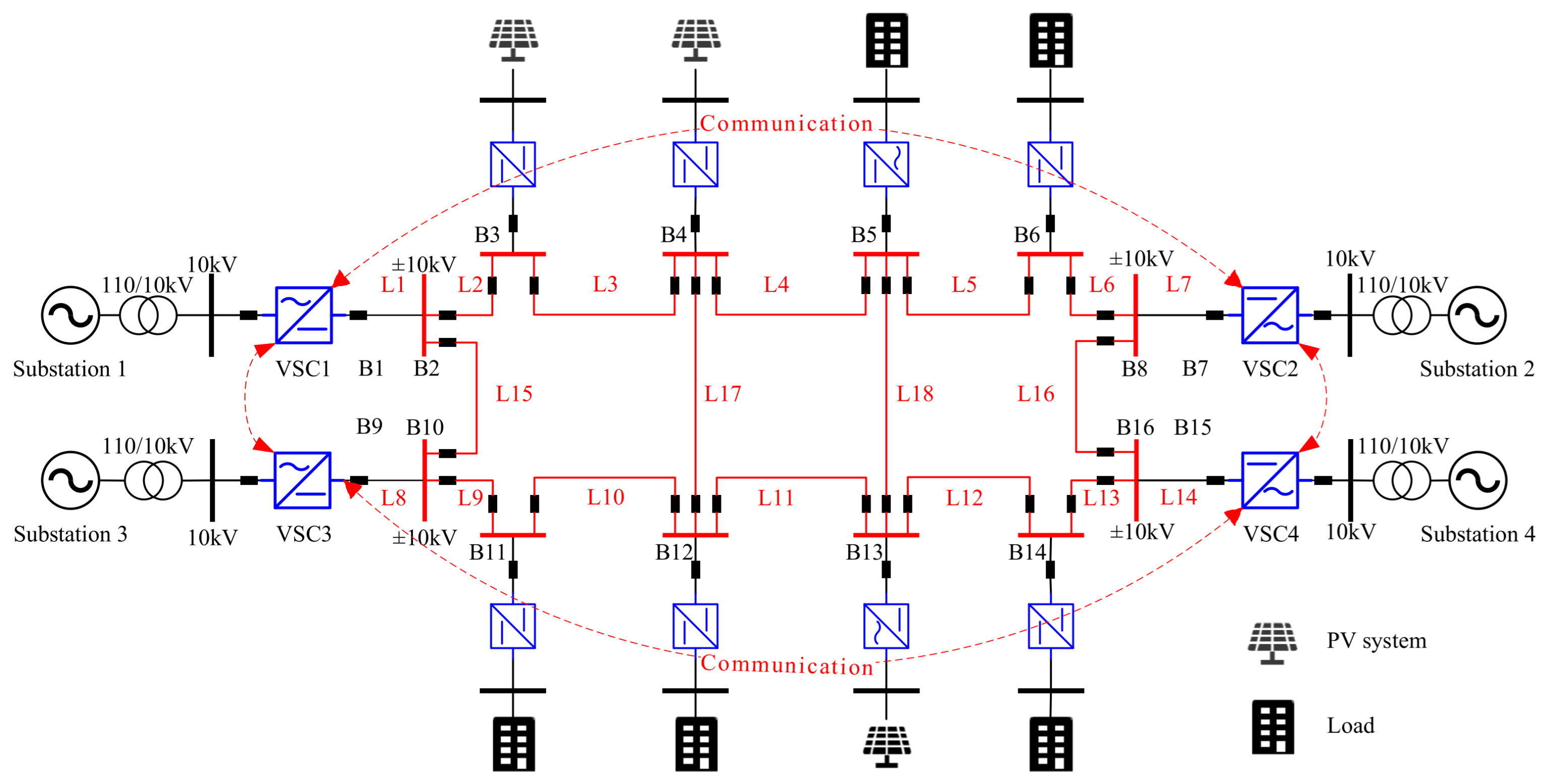
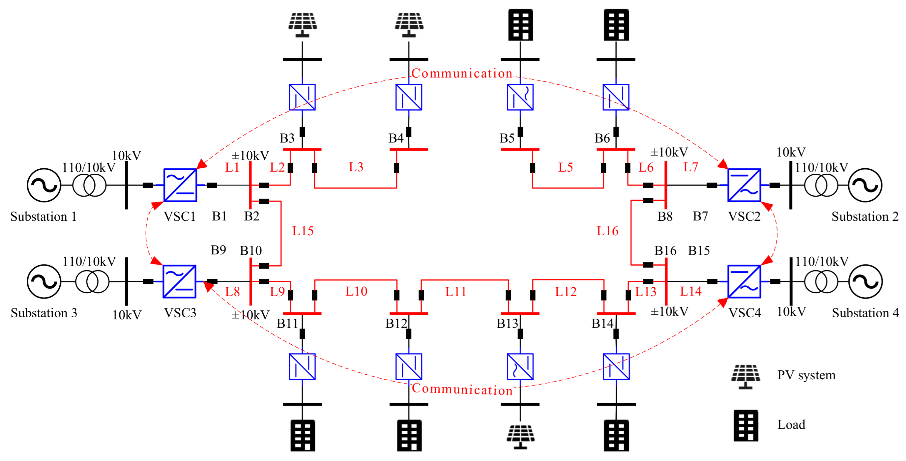
In this section, the proposed method is evaluated on a 4-terminal DCDN with a voltage level of ±10 kV, as shown in Figure 4, where the communication topology is also described. The generation/load parameters, line parameters and VSC parameters are shown in Table 2, Table 3 and Table 4, respectively.

4.1. Spectral Radius Analysis of the Closed-Loop System

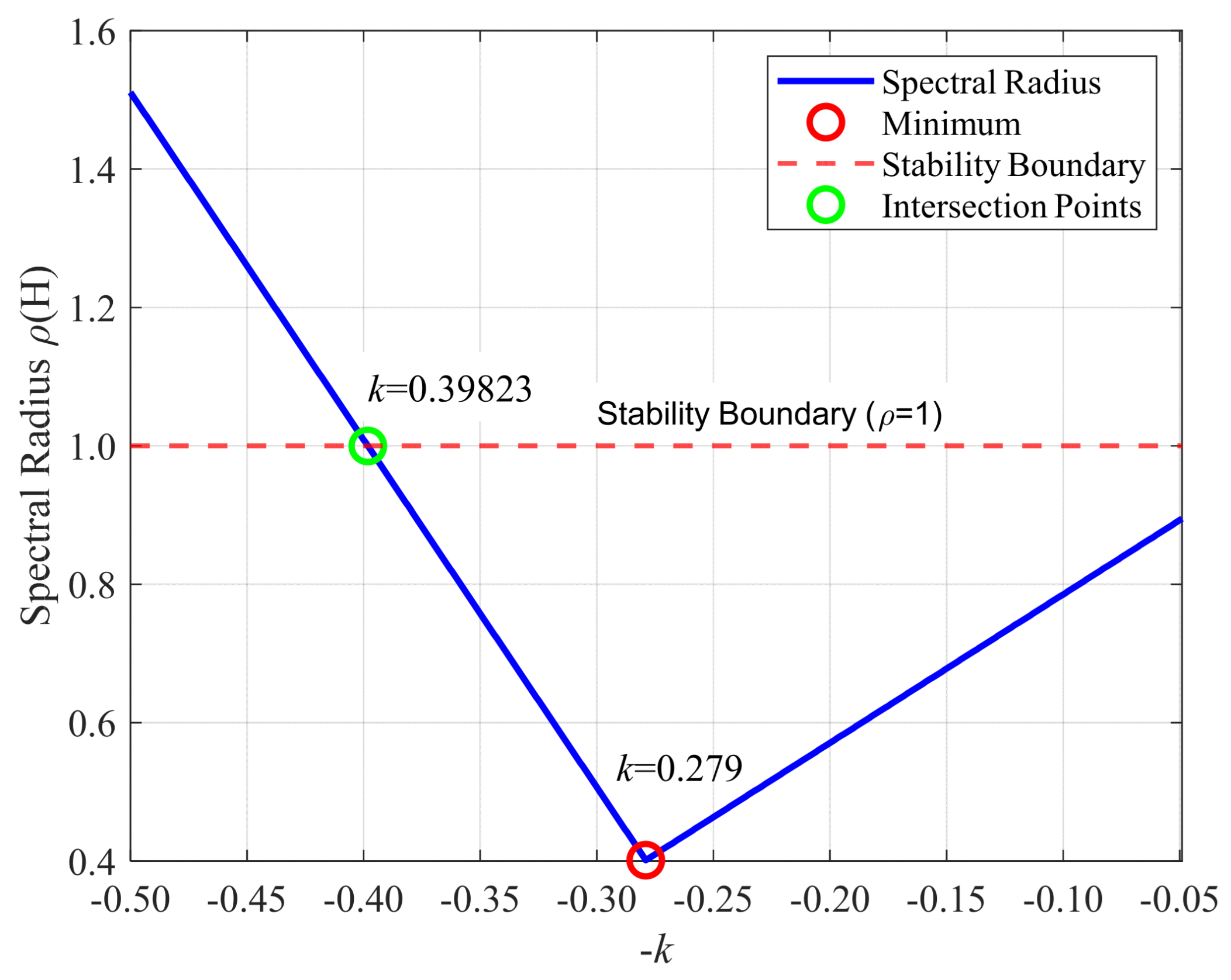
Based on the discrete-time LTI state space model, Figure 5 shows the variation in the spectral radius of the closed-loop system matrix with respect to the feedback control gain k. For simplicity, an identical feedback gain is applied to all VSCs. As observed from the figure, when −k increases from −0.5 to 0, the spectral radius ρ(H) first decreases and then increases, reaching its minimum value of 0.401 at k = 0.279. The dashed red line indicates the stability boundary (ρ(H) = 1). The system transitions from unstable to stable operation when k increases beyond 0.398, where ρ(H) drops below 1.

4.2. Performance Under Conventional Manual Gain Tuning

In this section, the feedback gains are determined through manual trial-and-error adjustment, with the primary objective of verifying the accuracy and validity of the power flow sensitivity-based state-space model. Considering the communication latency and the transient time constant of the system, the control period is set to 100 ms to ensure that state measurements are taken after transient processes have settled down. The initial voltages at the VSC buses are 1.0 p.u. Both α and β are set to 1. Two PV generation variation scenarios are designed:
(1)
At t = 1 s, the outputs of all PV units drop to half of the original values;
(2)
At t = 11 s, the outputs of all PV units restore to the original values.
Four control schemes are compared:
(1)
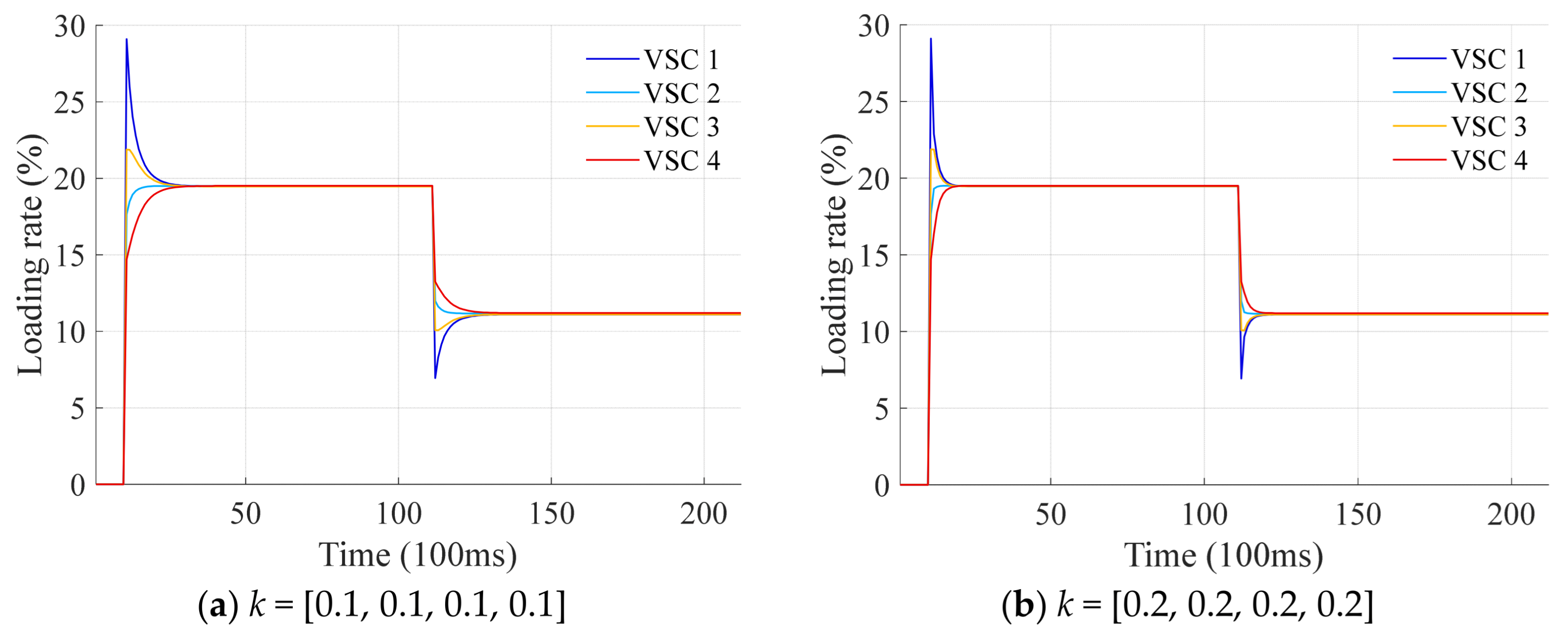
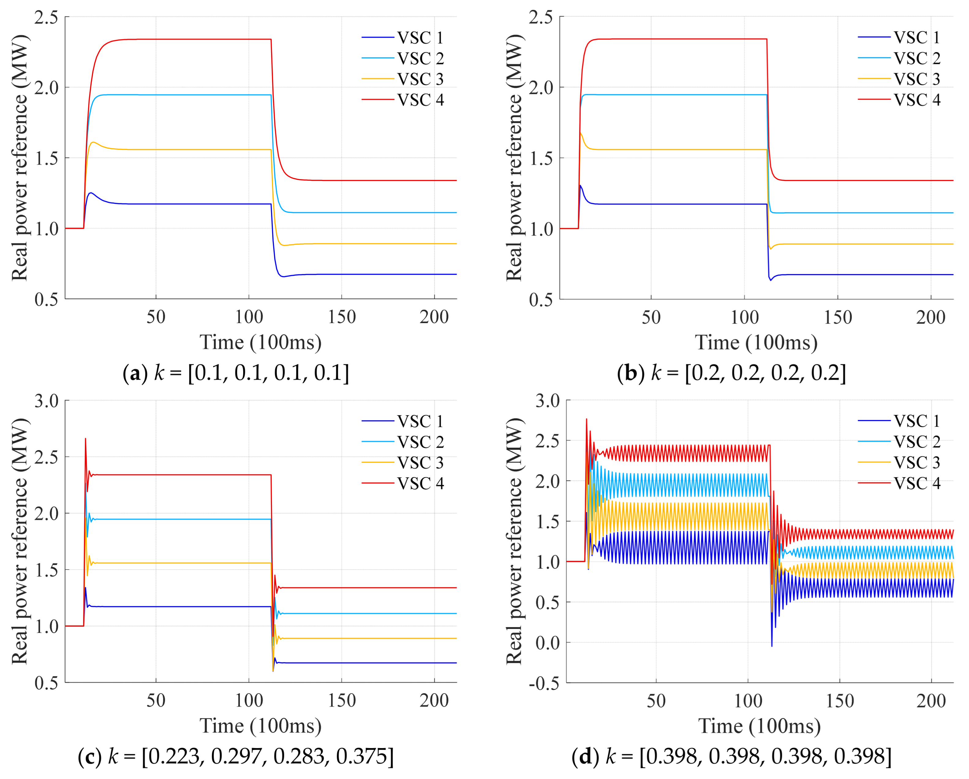
Scheme 1: the feedback gains are set uniformly as k = [0.1, 0.1, 0.1, 0.1];
(2)
Scheme 2: the feedback gains are set uniformly as k = [0.2, 0.2, 0.2, 0.2];
(3)
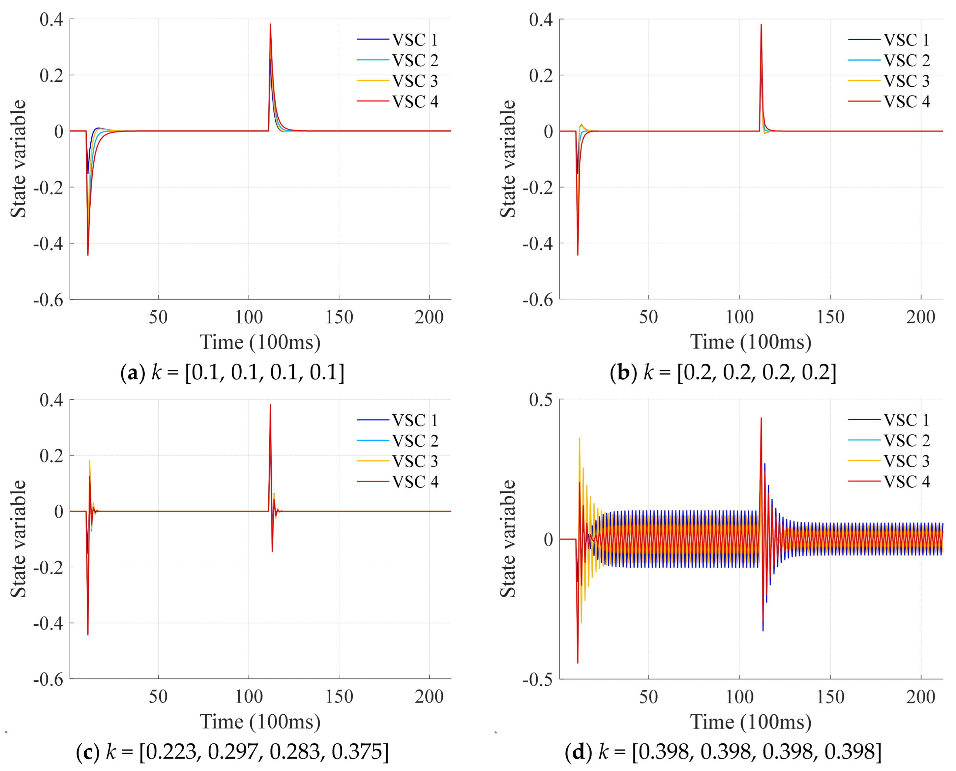
Scheme 3: the feedback gains are set as k = [0.223, 0.297, 0.283, 0.375], which is obtained by minimizing the spectral radius using the genetic algorithm;
(4)
Scheme 4: the feedback gains are set uniformly as k = [0.398, 0.398, 0.398, 0.398], which corresponds to the stability boundary point in Figure 5.
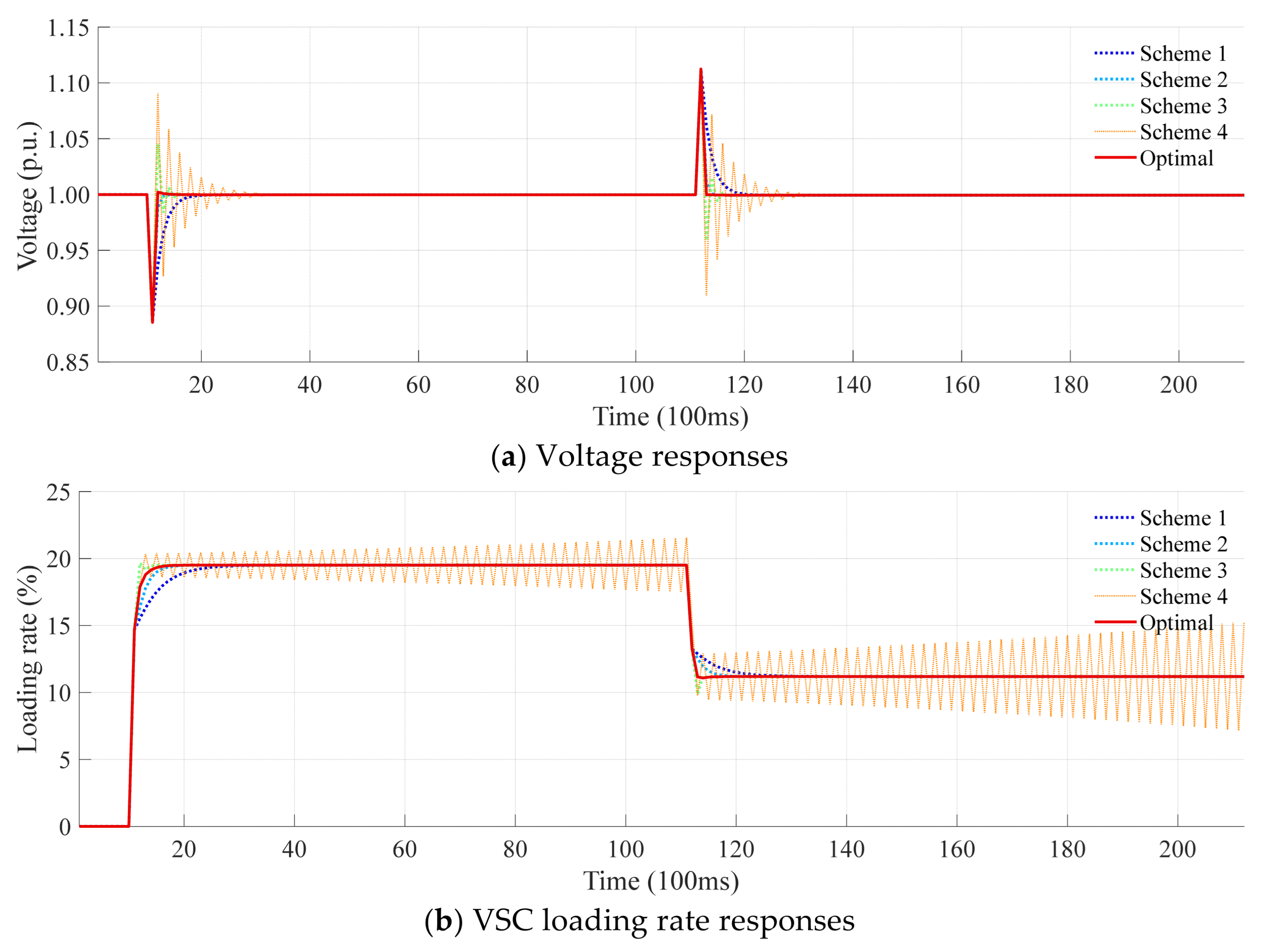
The voltage responses under different feedback control schemes are illustrated in Figure 6. When the PV outputs decrease, the voltages drop below 0.9 p.u., and all four controllers effectively restore them to 1.0 p.u. by adjusting the VSC power references. Similarly, when the PV outputs recover, the voltages exceed 1.1 p.u., and all controllers successfully regulate them back to 1.0 p.u. The main difference among the schemes lies in their dynamic performance:
(1)
Scheme 1 (k = [0.1, 0.1, 0.1, 0.1]) restores the voltage in 10 control cycles;
(2)
Scheme 2 (k = [0.2, 0.2, 0.2, 0.2]) exhibits a faster response, stabilizing the voltage within 4 control cycles;
(3)
Scheme 3 (k = [0.223, 0.297, 0.283, 0.375]) requires 8 control cycles to restore voltage, but introduces overshoot. Although this gain set is optimized via genetic algorithm for minimal spectral radius, it prioritizes stability and leads to overshoot due to aggressive power reference adjustments;
(4)
Scheme 4 (k = [0.398, 0.398, 0.398, 0.398]) results in more severe overshoot and brings the voltage back to 1.0 p.u. through damped oscillations.
Figure 6. The voltage responses under different feedback control schemes.
Energies 18 05382 g006
The VSC loading rate responses under different feedback control schemes are illustrated in Figure 7. When the PV outputs decrease, all VSCs inject more power into the system, resulting in significantly imbalanced loading rates. Due to its lowest capacity, VSC 1 experiences the highest loading rate. The first three control schemes effectively restore load balance by adjusting the VSCs’ power references. In contrast, Scheme 4 exhibits unattenuated oscillations in the loading rate curves, as the closed-loop system operates at the stability boundary. Similarly, when the PV outputs recover, all VSCs reduce their power injection, again leading to highly uneven loading rates, with VSC 1 showing the lowest loading rate owing to its limited capacity. The first three controllers successfully rebalance the loads, whereas Scheme 4 continues to display persistent oscillations for the same stability-related reason.
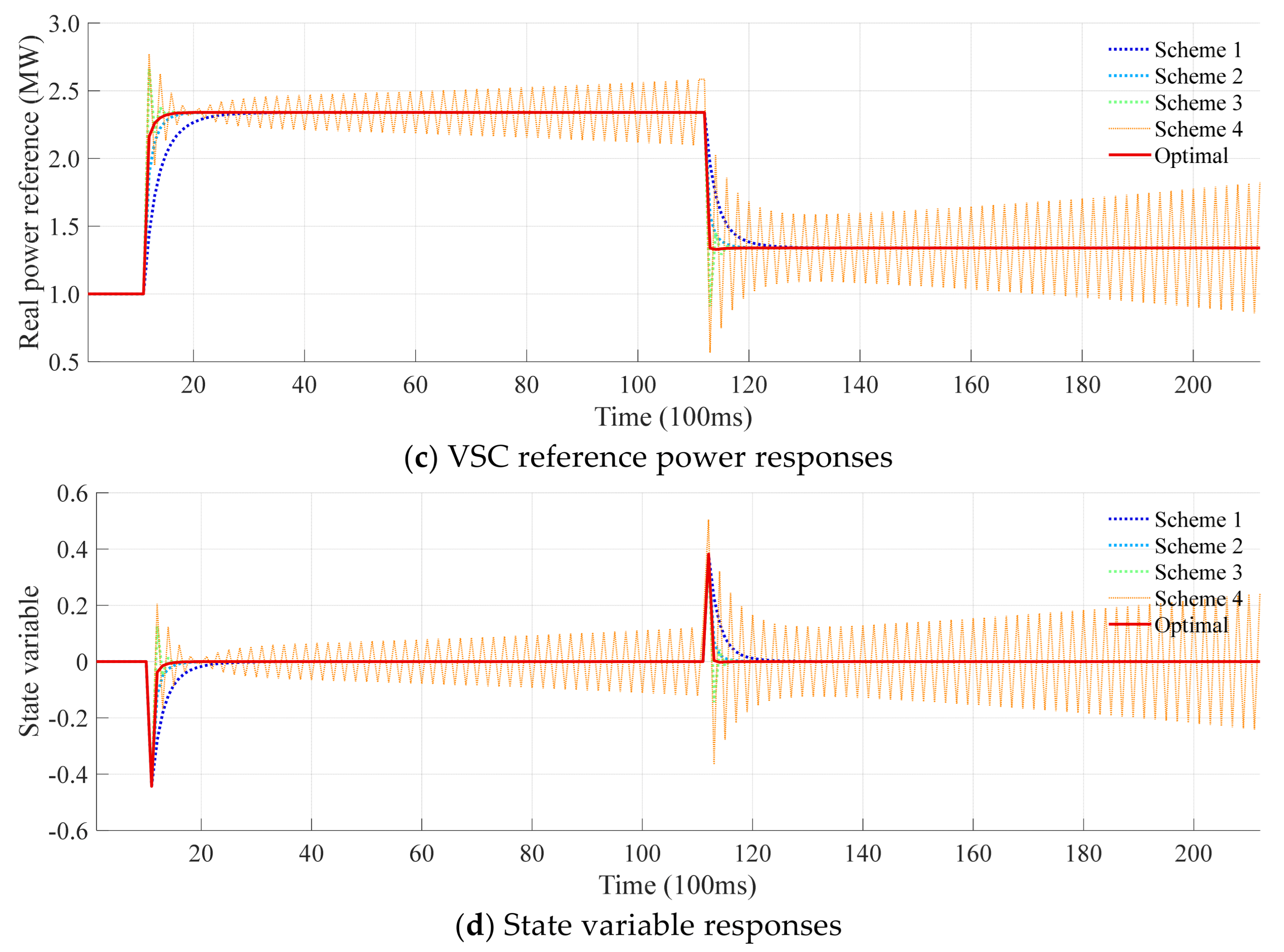
The power reference responses of the VSCs under different feedback control schemes are shown in Figure 8. When the PV outputs decrease, all VSCs increase their power injection into the system. The increase is highest from VSC 4, followed by VSC 2 and VSC 3, while VSC 1 contributes the least—consistent with their respective capacities (12 MW, 10 MW, 8 MW, 6 MW). This indicates that VSCs with larger capacities compensate for more power deficit. In Scheme 4, the power references of all VSCs exhibit persistent oscillations, consistent with the loading rate behavior in Figure 7, due to operation at the stability boundary. Similarly, when the PV outputs recover, all VSCs reduce their power injection, with VSC 4 decreasing the most, followed by VSC 2, VSC 3, and VSC 1, again aligning with their capacity ratings. Scheme 4 continues to show oscillatory behavior for the same stability-related reason.
The state variable responses of the VSCs under different feedback control schemes are shown in Figure 9. When the PV outputs decrease, the state variables of all VSCs shift to negative values, activating the controllers to regulate the states back to zero. While Schemes 1–3 suppress the deviations rapidly, Scheme 4 exhibits persistent oscillations around zero due to operation at the stability boundary. Similarly, when the PV outputs recover, the state variables deviate positively, triggering controller action. All schemes except Scheme 4 quickly restore the states to zero; Scheme 4 continues to show oscillatory behavior for the same stability-related reason.
Note that for Scheme 4, although large power oscillations exist, these oscillations do not affect the voltage in Figure 6d as all voltage are stabilized after a short oscillatory behavior. This phenomenon arises from the specific definition of the state variable in our controller design. Each local state variable combines both voltage deviation and loading rate deviation among neighboring VSCs. At the stability boundary, this composite state variable exhibits sustained oscillations to maintain critical stability. However, the voltage deviation component rapidly decays to zero due to the direct and strong coupling between power reference adjustments and nodal voltage regulation. In contrast, the loading rate deviation component continues oscillating because achieving exact load sharing requires continuous coordination through communication, which introduces phase delays that perpetuate oscillations. Thus, although the overall state variable oscillates, the voltage sub-component remains stable. On the other side, the power oscillations shown in Figure 8d are complementary—when some VSCs increase their power output, others decrease it proportionally. This compensatory behavior ensures that the total power injection into the network remains balanced with the total load demand at all times. Since voltage stability is fundamentally governed by real-power balance in DCDNs, the absence of net power surplus or deficit allows the system voltage to remain steady at the reference value. The VSC power oscillations, though significant individually, cancel each other’s impact on the grid voltage due to their complementary nature. Therefore, the voltage stability is maintained even amid power oscillations.
In summary, the simulation results validate that the proposed distributed control method’s capability to effectively achieve voltage regulation and power sharing simultaneously. Proper gain tuning enhances response speed while minimizing overshoot. Crucially, the novel power flow sensitivity-based state space model establishes a theoretical framework for rigorous parameter selection, ensuring closed-loop stability while optimizing dynamic performance.

4.3. Performance Validation and Comparison of the Proposed Optimization-Based Method

In this section, the performance of the proposed feedback control gain optimization method is evaluated and compared against the conventional manual trial-and-error tuning approach, which remains widely adopted in existing literature [12,13,14,15,16,18,19,20,21]. To further examine robustness under critical conditions, Scheme 4 is deliberately modified by replacing the feedback gain from 0.398 to 0.4, intentionally introducing an unstable gain scenario for validation. For the proposed optimization method, the parameters are configured as follows: γ target = 0.01 , θ max = 1 ° , δ = 0.05 , w m = 1 , w a = 20 , w s = 1000 . It is worth emphasizing that these settings are generally predetermined according to operational preferences and do not require frequent recalibration, enhancing practicality for real-world applications.
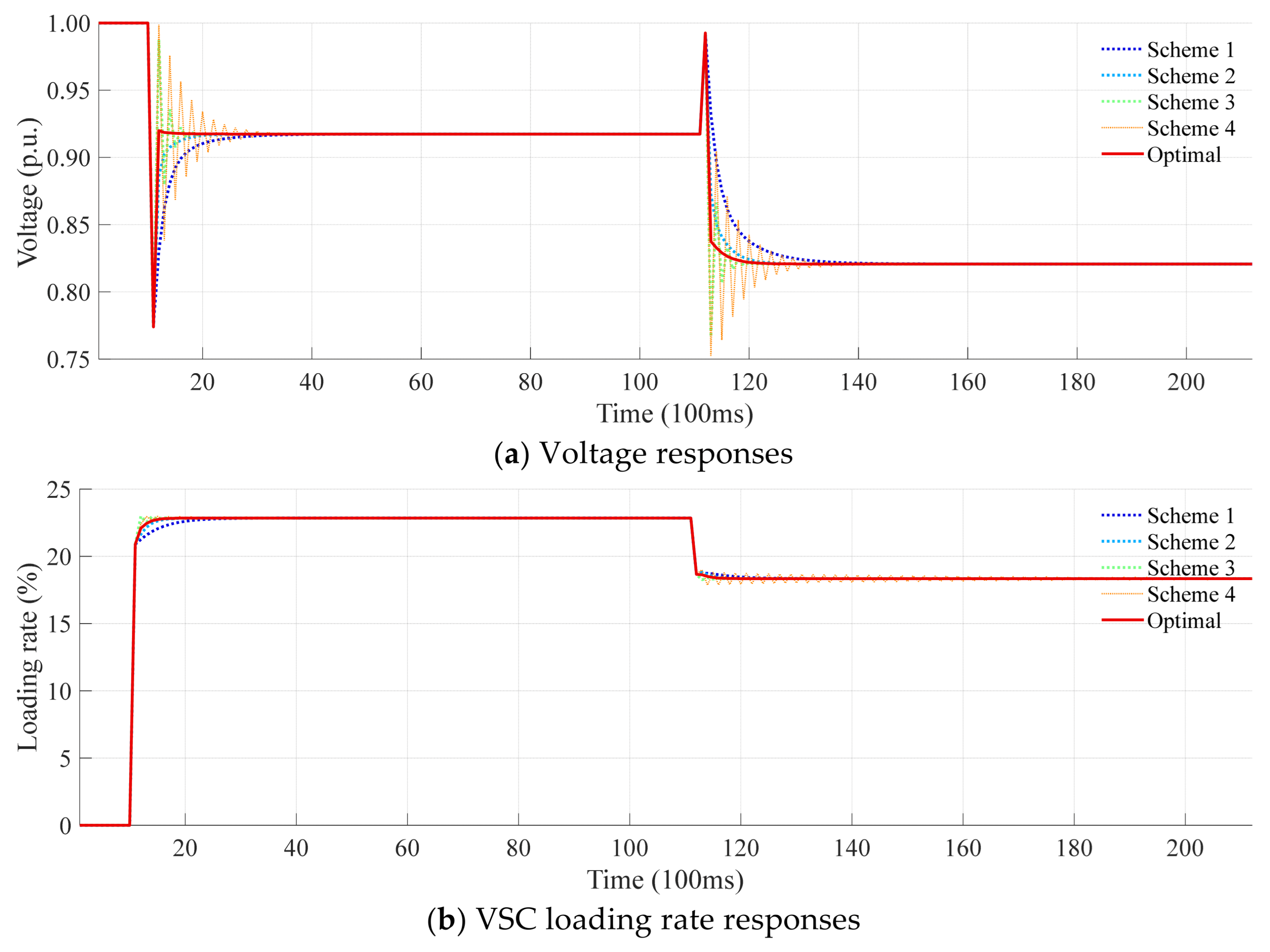
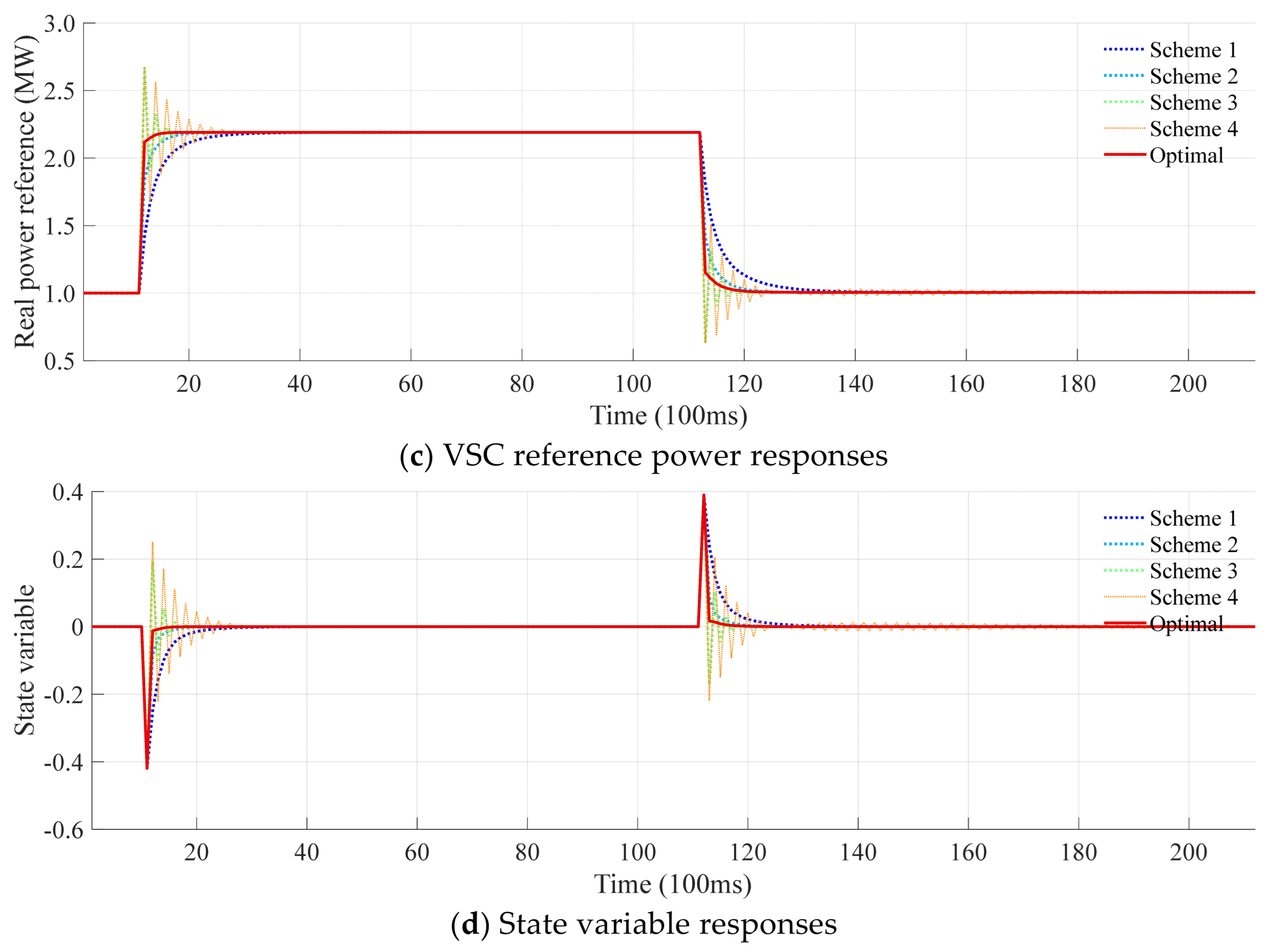
Comparative results across four manual tuning schemes and the proposed optimization-based method are illustrated in Figure 10, including voltage responses, loading rates, VSC reference power adjustments, and state variable behaviors. For conciseness, only the results of VSC 4 are displayed, as other VSCs exhibit similar trends. As clearly observed, the manually tuned parameters often lead to undesirable control outcomes such as oscillatory responses, significant overshoot, or sluggish recovery dynamics. In contrast, by simultaneously optimizing the eigenvalue modulus (governing convergence speed), eigenvalue angle (affecting overshoot and oscillation), and spectral radius (ensuring stability margin), the proposed method achieves rapid dynamic response without overshoot or instability. These results conclusively validate the effectiveness and superiority of the multi-objective optimization-based parameter design framework for feedback gain synthesis.

4.4. Performance Validation and Comparison Under Radial Topology

In this section, the performance of the proposed feedback control gain optimization method is evaluated and compared on a radial topology, which is obtained by deleting three lines B4–B12, B5–B13 and B4–B5, as shown in Figure 11. All test schemes and parameters remain the same as in previous sections.
Figure 12 depicts the variation in the spectral radius of the closed-loop system matrix with the feedback control gain k, where an identical gain is applied to all VSCs for simplicity. The results indicate that the system transitions from instability to stability when k exceeds the critical value of 0.40397, which defines the stability boundary.
Figure 13 compares the performance of VSC 4 under four manual tuning schemes and the proposed optimization-based method. Consistent with the results from the meshed topology, manual tuning often results in oscillatory responses, significant overshoot, or sluggish recovery. In contrast, the proposed method, which simultaneously optimizes the eigenvalue modulus, angle, and spectral radius, achieves a rapid and stable dynamic response without overshoot. An exception is Scheme 4, which remains stable in this radial topology because its feedback gain (0.398) is below the stability boundary of 0.40397. These results demonstrate the effectiveness and superiority of the multi-objective optimization framework for feedback gain synthesis in radial DCDNs.

5. Conclusions

Aiming at the challenges of design complexity and parameter adjustment difficulties in existing distributed controllers, a novel power flow sensitivity-based distributed cooperative control approach is proposed for voltage regulation and power sharing in droop-controlled DCDNs. A comprehensive sensitivity model is firstly established. Leveraging this sensitivity model, a discrete-time linear state-space model is developed for DCDNs and a distributed consensus controller is then designed.
The effectiveness of the proposed distributed control method is validated through thorough simulation analysis on a typical 4-terminal DCDN, with the following conclusions:
  • The proposed distributed control method achieves rapid voltage recovery and converter load sharing under a sparse communication network.
  • Thanks to the proposed power flow sensitivity-based state-space model, feedback gain design can be conducted in a systematic and principled manner such that the design complexity and parameter adjustment difficulties are greatly reduced while strictly ensuring closed-loop stability.
Future work will be focused on developing distributed control methods for simultaneous voltage regulation and power sharing based on a more detailed small-signal model. This refined model will incorporate higher-order dynamics of power converters, line impedances, and constant power loads, enabling more accurate representation of system behavior under various disturbances. State estimation techniques will be integrated to reconstruct the full system state, enabling the application of state feedback control based on the linear quadratic regulator. Furthermore, various practical implementation challenges such as communication delays, packet losses, and sensor noises will also be accommodated to enhance the controller’s robustness and practical applicability.

Author Contributions

Conceptualization, H.G. and D.L.; methodology, D.L.; investigation, N.J., Z.Z. and Y.P.; data curation, Z.Z. and Y.P.; writing—original draft, N.J. and D.L.; writing—review and editing, H.G. and X.Z.; funding acquisition, H.G. and X.Z. All authors have read and agreed to the published version of the manuscript.

Funding

This work was funded by the State Grid East Inner Mongolia Electric Power Company grant number 526604240006.

Data Availability Statement

The data presented in this study are available on request from the corresponding author. (The data are not publicly available due to privacy restrictions.).

Conflicts of Interest

Authors Nan Jiang, He Gao, Xingyu Zhang, Zhe Zhang and Yufei Peng are employed by the Electric Power Research Institute of State Grid Inner Mongolia East Electric Power Co., Ltd. The remaining authors declare that this research was conducted in the absence of any commercial or financial relationships that could be construed as potential conflicts of interest.

Nomenclature

B m × m Input matrix of the discrete-time LTI state model.
f i ( V ) Nonlinear power equation corresponding to bus i.
G i j The (i,j)th element of the network nodal conductance matrix.
H m × m Closed-loop system matrix, H = I B K .
J n × n Jacobian matrix of power injections with respect to bus voltages at the steady-state operating point, whose (i,j)th element is f i ( V ) / V j .
J ( K ) Total cost function for optimization of feedback control gains.
J m ( K ) Cost to penalize the slow convergence of the system’s response.
J a ( K ) Cost to penalize excessive overshoot and oscillatory behavior of the system’s dynamic response.
J s ( K ) Cost to enforces the stability margin of the closed-loop system.
K m × m Diagonal feedback control gain matrix.
k i Feedback control gain of the VSC at bus i.
L i Loading rate of the VSC at bus i.
Δ L VSC m Loading rate vector of all VSCs.
M m × m Sensitivity matrix between the VSC loading rate vector and the VSC reference power vector.
mNumber of all VSCs in the DCDN.
nNumber of all buses in the DCDN.
𝒩 i Set of all neighboring buses of bus i (including bus i itself).
𝒩 i Cardinality of 𝒩 i .
Δ P n Vector of all power injection increments.
Δ P ref m Vector of reference power increments of all VSC buses.
Δ P nonVSC n m Vector of power increments of all non-VSC buses.
P i Specified power injection of the non-VSC bus i.
P i , ref Power reference of the VSC at bus i
P i , max Capacity of the VSC at bus i.
ρ ( H ) Spectral radius of the closed-loop system matrix H .
R i Droop coefficient of the VSC at bus i.
S m × m Sensitivity matrix between the VSC bus voltage vector and the VSC reference power vector.
u ( k ) m Control variable vector during the kth control.
V n Vector of all bus voltages.
Δ V n Vector of all bus voltage increments.
Δ V VSC m Vector of bus voltage increments of all VSC buses.
Δ V nonVSC n m Vector of bus voltage increments of all non-VSC buses.
V i Voltage of the bus i.
V i , ref Voltage reference of the VSC at bus i.
V ref Voltage reference value (fixed at 1.0 p.u.).
w m , w a , w s Weighting coefficients of costs for optimization of control gains.
x i local state variable of the VSC at bus i.
x ( k ) m State variable vector during the kth control.
y ( k ) m Output variable vector during the kth control.
λ i The i-th eigenvalue of the closed-loop system matrix H .
θ i Angle of λ i .
θ max Maximum allowable eigenvalue angle for overshoot suppression.
γ target Target eigenvalue magnitude (modulus) for convergence speed regulation.
δ Stability margin quantifying the distance from the stability boundary.

References

  1. Fu, Q.; Du, W.; Wang, H.; Ma, X.; Xiao, X. DC voltage oscillation stability analysis of DC-voltage-droop-controlled multiterminal DC distribution system using reduced-order modal calculation. IEEE Trans. Smart Grid 2022, 13, 4327–4339. [Google Scholar] [CrossRef]
  2. Deng, W.; Pei, W.; Wu, Q.; Zhuang, Y. Analysis of interactive behavior and stability of low-voltage multiterminal DC system under droop control modes. IEEE Trans. Power Electron. 2022, 69, 4327–4339. [Google Scholar] [CrossRef]
  3. Liu, C.; Li, B.; Zhang, Y.; Jiang, Q.; Liu, T. The LCC type DC grids forming method and fault ride-through strategy based on fault current limiters. Int. J. Electr. Power Energy Syst. 2025, 170, 110843. [Google Scholar] [CrossRef]
  4. Gao, F.; Kang, R.; Cao, J.; Yang, T. Primary and secondary control in DC microgrids: A review. J. Mod. Power Syst. Clean Energy 2019, 7, 227–242. [Google Scholar] [CrossRef]
  5. Xie, X.; Quan, X.; Wu, Z.; Cao, X.; Hu, W.; Dou, X.; Hu, Q. A novel peer-to-peer control strategy for multiterminal DC distribution systems. IEEE Trans. Smart Grid 2023, 14, 785–797. [Google Scholar] [CrossRef]
  6. Wang, Y.; He, J.; Zhao, Y.; Liu, G.; Sun, J.; Li, H.; Wang, C. Equal loading rate based master–slave voltage control for VSC based DC distribution systems. IEEE Trans. Power Deliv. 2020, 35, 2252–2259. [Google Scholar] [CrossRef]
  7. Xie, X.; Quan, X.; Wu, Z.; Cao, X.; Dou, X.; Hu, Q. Adaptive master-slave control strategy for medium voltage DC distribution systems based on a novel nonlinear droop controller. IEEE Trans. Smart Grid 2021, 12, 4765–4777. [Google Scholar] [CrossRef]
  8. Liu, Q.; Chen, H.; Liang, D.; Ji, X.; Zhang, L. Collaborative optimization of reference powers and droop coefficients in DC distribution networks considering flexibility enhancement. Sustain. Energy Grids Netw. 2024, 39, 101416. [Google Scholar] [CrossRef]
  9. Liu, Q.; Wang, Y.; Wang, S.; Liang, D.; Zhao, Q.; Zhao, X. Voltage regulation strategy for DC distribution networks based on coordination of centralized control and adaptive droop control. IEEE Trans. Power Deliv. 2022, 37, 3730–3739. [Google Scholar] [CrossRef]
  10. Sun, P.; Pinthurat, W.; Li, G.; Khalid, M.; Town, G.E.; Konstantinou, G. Adaptive droop control in VSC-based MT-MVDC distribution systems considering ESS participationn. IEEE Trans. Energy Convers. 2025, 40, 761–772. [Google Scholar] [CrossRef]
  11. Moradi, M.; Heydari, M.; Zarei, S.F. An overview on consensus-based distributed secondary control schemes in DC microgrids. Elect. Power Syst. Res. 2023, 225, 109870. [Google Scholar] [CrossRef]
  12. Nasirian, V.; Moayedi, S.; Davoudi, A.; Lewis, F.L. Distributed cooperative control of DC microgrids. IEEE Trans. Power Electron. 2015, 30, 2288–2303. [Google Scholar] [CrossRef]
  13. Li, Y.; Zhang, Z.; Dragičević, T.; Rodriguez, J. A unified distributed cooperative control of DC microgrids using consensus protocol. IEEE Trans. Smart Grid 2021, 12, 1880–1892. [Google Scholar] [CrossRef]
  14. Sahoo, S.; Mishra, S. A distributed finite-time secondary average voltage regulation and current sharing controller for DC microgrids. IEEE Trans. Smart Grid 2019, 10, 282–292. [Google Scholar] [CrossRef]
  15. Li, X.; Hu, C.; Luo, S.; Lu, H.; Piao, Z.; Jing, L. Distributed hybrid-triggered observer-based secondary control of multi-bus DC microgrids over directed networks. IEEE Trans. Circuits Syst. I 2025, 72, 2467–2480. [Google Scholar] [CrossRef]
  16. Du, Y.; Lu, X.; Tang, W. Accurate distributed secondary control for DC microgrids considering communication delays: A surplus consensus-based approach. IEEE Trans. Smart Grid 2022, 13, 1709–1719. [Google Scholar] [CrossRef]
  17. Yuan, Q.; Wang, Y.; Liu, X.; Lei, Y. Distributed fixed-time secondary control for DC microgrid via dynamic average consensus. IEEE Trans. Sustain. Energy 2021, 12, 2008–2018. [Google Scholar] [CrossRef]
  18. Shafiee, P.; Khayat, Y.; Batmani, Y.; Shafiee, Q.; Guerrero, G.M. On the design of event-triggered consensus-based secondary control of DC microgrids. IEEE Trans. Power Syst. 2022, 37, 3834–3846. [Google Scholar] [CrossRef]
  19. Wang, Z.; Wu, W.; Zhang, B. A fully distributed power dispatch method for fast frequency recovery and minimal generation cost in autonomous microgrids. IEEE Trans. Smart Grid 2016, 7, 19–31. [Google Scholar] [CrossRef]
  20. Xu, Y.; Guo, Q.; Sun, H.; Fei, Z. Distributed discrete robust secondary cooperative control for islanded microgrids. IEEE Trans. Smart Grid 2019, 10, 3620–3629. [Google Scholar] [CrossRef]
  21. Yang, G.; Ding, L.; Ye, M.; Xiao, S.; Yue, D. Distributed accurate current sharing for multi-bus DC microgrids with minimizing voltage regulation deviations: A game-theoretic approach. IEEE Trans. Smart Grid 2025, 16, 2725–2737. [Google Scholar] [CrossRef]
  22. Lee, G.Y.; Ko, B.S.; Cho, J.; Kim, R.Y. A distributed control method based on a voltage sensitivity matrix in DC microgrids with low-speed communication. IEEE Trans. Smart Grid 2019, 10, 4–15. [Google Scholar] [CrossRef]
  23. Liu, Q.; Zhang, L.; Zhang, H.; Wang, S.; Ji, X. Distributed secondary optimal control with fast voltage recovery and minimum generation cost for islanded DC microgrids. IEEE Trans. Smart Grid 2025, 16, 4–15. [Google Scholar] [CrossRef]
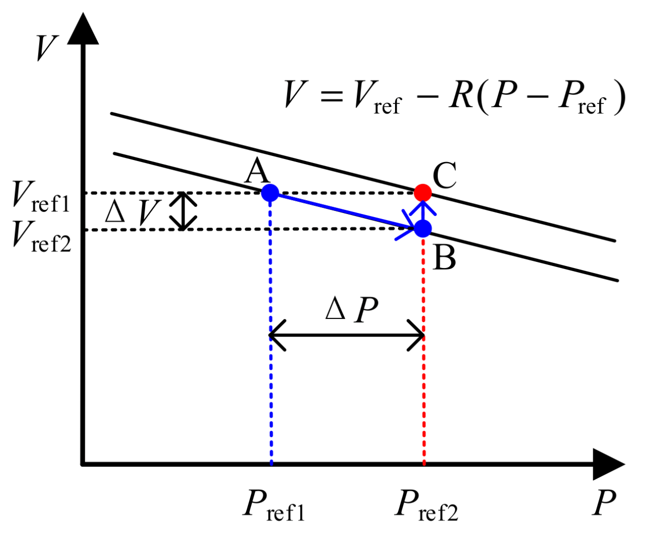
Figure 1. Illustration of the V-P droop control.
Energies 18 05382 g001
Figure 2. Communication topology of a 4-terminal DCDN.
Energies 18 05382 g002
Figure 3. Block diagram of the proposed distributed control method.
Energies 18 05382 g003
Figure 4. Single-line diagram of the 4-terminal DCDN.
Energies 18 05382 g004
Figure 5. The spectral radius curve of the closed-loop system matrix with respect to the feedback control gain k.
Energies 18 05382 g005
Figure 7. The VSC loading rate responses under different feedback control schemes.
Energies 18 05382 g007aEnergies 18 05382 g007b
Figure 8. The VSC reference power responses under different feedback control schemes.
Energies 18 05382 g008
Figure 9. The state variable responses under different feedback control schemes.
Energies 18 05382 g009
Figure 10. Comparative results across four manual tuning schemes and the proposed optimization-based method (VSC 4).
Energies 18 05382 g010aEnergies 18 05382 g010b
Figure 11. Single-line diagram of the 4-terminal DCDN (radial topology).
Energies 18 05382 g011
Figure 12. The spectral radius curve of the closed-loop system matrix with respect to the feedback control gain k. (radial topology).
Energies 18 05382 g012
Figure 13. Comparative results across four manual tuning schemes and the proposed optimization-based method (VSC 4, radial topology).
Energies 18 05382 g013aEnergies 18 05382 g013b
Table 1. Comparison of references.
ReferencesSystem ModelDirect Feedback Control?Stability/Convergence AnalysisNeeds Gain Tuning?
[12]Small signal modelAverage voltage observerNoneY
[13]Large signal modelAverage voltage observerInput-to-state stability analysisY
[14]Model-freeAverage voltage observerLyapunov stability analysisY
[15]Model-freeAverage voltage observerLyapunov stability analysisY
[16]Small signal modelAverage voltage observerDelay-dependent stability analysisY
[17]Model-freeAverage voltage observerLyapunov stability analysisN
[18]Small signal modelDirect feedback controlLyapunov stability analysisY
[19]Power flow modelDirect feedback controlConvergence analysisY
[20]Power flow modelDisturbance estimatorConvergence analysisY
[21]Power flow modelGlobal state observerConvergence analysisY
[22]Power flow modelDirect feedback controlPole-zero analysisN
[23]Power flow modelGlobal state observerSchur stability analysisN
This paperPower flow modelDirect feedback controlSchur stability analysisN
Table 2. Generation/load parameters of the test system.
BusB3B4B5B6B11B12B13B14
Load (MW)−2−22222−22
Table 3. Line parameters of the test system (0.1 Ω/km).
LineL1L2L3L4L5L6L7L8L9
Length (km)0.20.90.50.90.50.50.20.20.9
LineL10L11L12L13L14L15L16L17L18
Length (km)0.50.90.50.50.20.90.90.90.9
Table 4. VSC parameters of the test system.
VSCVSC 1VSC 2VSC 3VSC 4
Capacity (MW)610812
Droop coefficient (kV/MW)1.51.51.51.5
Disclaimer/Publisher’s Note: The statements, opinions and data contained in all publications are solely those of the individual author(s) and contributor(s) and not of MDPI and/or the editor(s). MDPI and/or the editor(s) disclaim responsibility for any injury to people or property resulting from any ideas, methods, instructions or products referred to in the content.