Article

Temperature Field Analysis and Experimental Verification of Mining High-Power Explosion-Proof Integrated Variable-Frequency Permanent Magnet Motor

1
Henan Province Engineering Research Center of Ultrasonic Technology Application, Pingdingshan University, Pingdingshan 467000, China
2
Wolong Electric Nanyang Explosion Protection Group Co., Ltd., Nanyang 473000, China
*
Author to whom correspondence should be addressed.
These authors contributed equally to this work.
Energies 2025, 18(20), 5369; https://doi.org/10.3390/en18205369 (registering DOI)
Submission received: 3 September 2025 / Revised: 1 October 2025 / Accepted: 11 October 2025 / Published: 12 October 2025
(This article belongs to the Special Issue Advanced Technology in Permanent Magnet Motors)

Abstract

An efficient cooling configuration is critical for ensuring the safe operation of electrical machines and is key for optimizing the iterative design of motors. To improve the heat dissipation performance of high-power, explosion-proof, integrated variable-frequency permanent magnet motors used in mining and reduce the risk of permanent magnet demagnetization, this study considers a 1600 kW mining explosion-proof variable-frequency permanent magnet motor as its research object. Based on the zigzag-type water channel structure of the frame, a novel rotor-cooling scheme integrating axial–radial ventilation structures and axial flow fans was proposed. The temperature field of the motor was simulated and analyzed using a fluid–thermal coupling method. Under rated operating conditions, the flow characteristics of the frame water channel and the temperature distribution law inside the motor were compared when the water supply flow rates were 5.4, 4.8, 4.2, 3.6, 3, 2.4, and 1.8 m3/h, respectively, and the relationship between the motor temperature rise and the variation in water flow rate was revealed. A production prototype was developed, and temperature rise tests were conducted for verification. The test results were in good agreement with the simulation calculation results, thereby confirming the accuracy of the simulation calculation method. The results provide an important reference for enterprises in the design optimization and upgrading of high-power explosion-proof integrated variable-frequency permanent-magnet motors.

1. Introduction

With the accelerated iteration and upgrading of coal mine mechanical equipment to satisfy the technical requirements of safe production, energy conservation, and consumption reduction in coal mines, flame-proof integrated permanent magnet motors have become crucial in the motor field. The continuous development and application of frequency conversion technology and variable-frequency speed control devices in coal mine equipment are driving the development of explosion-proof permanent magnet motors for high-tech products [1,2,3].
Considering the operating condition requirements and application scenario characteristics of transmission equipment in underground coal mines, traditional asynchronous motors exhibit low efficiency, whereas variable-frequency permanent magnet motor systems feature a small size and high power density. Therefore, the development of high-power flameproof integrated variable-frequency motors with an integrated structure, excellent performance, and high reliability is crucial for low-profile fully mechanized mining equipment and is a key factor in ensuring safe coal production [4]. The small size of an integrated device comprising a frequency converter and motor makes it difficult to dissipate heat efficiently in the device. In particular, higher requirements are imposed on the electromagnetic, cooling, and insulation structure designs of high-power flameproof permanent magnet motors used in mines. Thus, the main problem is improving the heat dissipation efficiency [5]. The shell water-cooling method is widely adopted for cooling flameproof permanent magnet motors used in mines. Specifically, shell water cooling achieves efficient cooling of the stator through direct heat exchange between the motor shell and the stator. For a rotating rotor, a limited heat exchange path results in low cooling efficiency. This further causes a problem in motor operation, where the stator has a low temperature rise and the rotor has a high temperature rise, resulting in a large temperature gradient between the stator and rotor components. The poor cooling effect on the rotor permanent magnets makes the “barrel effect” particularly significant. Therefore, in-depth research on efficient rotor cooling methods and cooling systems for flameproof permanent magnet motors used in mines is crucial. This study aims to enable a cooling system to control the temperature of permanent magnets within the safe operation range, with the temperature increase meeting the allowable limits of insulation classes, thereby ensuring the long-term stable operation of the motor [6,7,8].
Han et al. employed a software simulation analysis and adopted a three-dimensional Computational Fluid Dynamics (CFD) method to reveal the distribution law of the internal thermal flow field in vertical motors [9]. Karakatsanis focused on the design, analysis, and comparison of permanent-magnet synchronous motors (PMSMs) and Induction Motors (IMs) in marine electric propulsion systems, providing a basis for selecting appropriate motors for ship electrification [10]. Cao et al. adopted a combined method of CFD numerical simulation and experiment to conduct a comparative analysis of the distribution characteristics of the internal flow and temperature fields of a motor under single and double ventilation path conditions [11]. Wang et al. took a 48-slot water-cooled PMSM as the research object. By coupling the flow and temperature fields, they simulated the three-dimensional temperature of the motor under rated operating conditions, obtained the three-dimensional temperature distribution law of the motor, and experimentally verified the simulation results [12]. Li et al. established a real-time thermal model applicable to PMSMs. They described the relationship between the stator iron loss, current, and rotational speed, as well as the variation in the heat dissipation capacity of the shell with the rotational speed using equations. Experiments verified the accuracy of the model in predicting the temperatures of the windings and permanent magnets, with an error of less than 5% [13]. Du et al. focused on high-power high-speed permanent magnet motors, calculated the power loss under rated load through finite element analysis, and compared the temperature distributions of four cooling schemes. They investigated the effects of the axial flow channels, cooling media, sleeve thickness, and thermal conductivity on rotor temperature. Additionally, they adopted an improved loss separation method to extract various components of loss from the total loss and verified the theoretical analysis results through prototype experiments [14]. Wu et al. focused on the mine-used flameproof external-rotor PMSM. They adopted a fluid–structure interaction method to analyze the temperature distribution under the three cooling schemes. By optimizing the heat sink parameters, fillet radius of the fluid channel, and water flow velocity, they compared the cooling effects of different schemes. Experiments verified the consistency between the temperature field calculation results considering the thermal deformation and measured values [15]. Sequeira et al. established a thermal model for interior permanent magnet motors (IPMs). They verified the accuracy of the model using experimental data and finite element method (FEM) simulations. They analyzed the influence of the contact thermal resistance of each stator layer on the temperature distribution and found that the contact thermal resistance between the bushing and laminations was the most sensitive parameter. The experimental results showed that the error between the maximum temperatures of the slot windings and end windings predicted by the model and the measured values was less than 4% [16]. Zhang et al. proposed a semi-submerged cooling technology that involves configuring magnetic flux gaps in the alternating stator teeth of modular permanent magnet motors to serve as additional cooling channels. A liquid cooling medium was introduced into the stationary components to significantly reduce the temperature while preventing leakage into the rotating components. Experiments verified the effectiveness of this scheme in reducing the temperatures of the stator ends and rotor magnets, and it was found to be suitable for the thermal management of high-torque-density motors [17]. Nguyen et al. proposed a thermal analysis model for a PMSM that combined thermal network and analytical methods. They calculated the temperatures of the internal components using the thermal equivalent circuit method and employed an analytical method to predict the temperature distribution in the slot region of the stator. Using a 24-slot/6-pole prototype as an example, they compared the FEM simulation results with experimental data, verifying the accuracy of the proposed model in predicting the temperatures of the windings and permanent magnets. This model is particularly suitable for the thermal management of high-speed and high-power motors [18]. Zhu et al. established a three-dimensional fluid–thermal coupling calculation model for a large-capacity synchronous condenser (LSC). They investigated the hydrodynamic temperature and its distribution in the end region, and discussed the influence of the proposed structure on the temperature increase (TR) [19]. Gao et al. proposed a hybrid analysis method based on the subdomain and magnetic reluctance network methods, which improved the analytical calculation accuracy of the magnetic and temperature fields of motors [20]. Yi et al. verified the accuracy of a thermal grid model through fluid–structure interaction simulations and prototype tests, providing an efficient tool for thermal safety assessment and optimization in the fault-tolerant design of motors [21]. Liu et al. designed a novel Dual-Stator Permanent Magnet Wind Power Generator (DSPMWPG) to address the motor heat dissipation issue caused by complex structures and high loss density, and conducted calculations and analyses of its loss and electromotive force [22]. Numerous thermal simulation results [23,24] have shown that simulation technology can be effectively applied in the optimization of cooling structure design [25,26,27]. The research object of this study is a 1600 kW mine-used high-power flameproof permanent magnet motor that adopts an air–water hybrid heat dissipation method. Its cooling structure combines the water cooling method with the machine base and end cover connected in series, and the internal circulating air cooling method of the permanent magnet motor. Furthermore, based on fluid–thermal coupling, a temperature field simulation analysis was conducted to analyze and compare the flow velocity, pressure drop, and heat transfer effect under different water supply flow rate conditions. This study provides a reference for the cooling structure design and optimization of permanent magnet motors. However, based on the current progress of relevant research, the existing cooling schemes have limitations in three aspects: first, insufficient power adaptability—most studies focus on small- and medium-power motors, and there is a lack of targeted cooling design for 1600 kW-class mining flameproof motors; second, low rotor heat dissipation efficiency—existing schemes mostly emphasize stator water cooling or single ventilation structures, failing to form an “axial–radial” cooperative heat dissipation path for the rotor, which results in limited temperature control effect on permanent magnets; third, poor coordination between flameproof performance and heat dissipation—traditional cooling structures tend to cause narrow flow channels and increased eddy current losses when meeting flameproof standards, making it difficult to balance heat dissipation efficiency and safety requirements. To address the above research gaps, this study takes a 1600 kW mining flameproof integrated variable-frequency permanent magnet motor as the research object and proposes a composite cooling scheme consisting of an axial–radial ventilation structure, a return-type water channel, and an axial flow fan. Specifically, the return-type water channel is used to enhance the water cooling efficiency of the motor base; the axial–radial ventilation ducts are relied on to construct a dual-path heat dissipation network for the rotor, featuring “axial heat conduction belts and radial heat dissipation flows”; and the axial flow fan is matched to improve the internal air circulation rate, thereby solving the bottleneck of rotor heat dissipation. In this study, a fluid–thermal coupling method was adopted to simulate and analyze the distribution laws of the motor’s flow field and temperature field under a water supply flow rate range of 1.8–5.4 m3/h, and to reveal the influence mechanism of flow rate on temperature rise and pressure drop. A prototype was developed based on the simulation results, and the effectiveness of the proposed scheme was verified using temperature rise tests. This study provides a reference basis for the cooling structure design, optimization, and upgrading of permanent magnet motors.

2. Research Object and Methods

2.1. Structural Design of High-Power Explosion-Proof Variable-Frequency Permanent Magnet Motors

A variable-frequency integrated unit primarily comprises three components: a frequency converter, reactor, and variable-frequency motor. The outlet temperature of the motor functions as the inlet temperature of the frequency converter and reactor, in accordance with the water circuit structure of the variable-frequency integrated unit. This study focuses on the discussion and analysis of the permanent magnet motor design segment. The permanent magnet used was a neodymium–iron–boron (NdFeB)-grade N38SH. The maximum allowable operating temperature of the material used was 150 °C. The design parameters of the permanent magnet motor are listed in Table 1, and their overall structures are illustrated in Figure 1.
In this study, the “axial–radial ventilation + axial flow fan” combination was selected. Its fundamental theoretical basis lies in addressing the limitations of traditional single-ventilation modes, enabling more uniform and efficient thermal management in both the axial and radial dimensions of the motor. This combination is particularly suitable for high-power-density motors and offers the following three advantages:
  • Axial Aspect: The axial flow fan provides a strong main airflow, ensuring basic cooling performance.
  • Radial Aspect: Radial air ducts accurately direct cold air to internal heat sources, such as the rotor and stator core, effectively reducing the temperature of hotspots.
  • Synergistic Effect: The integration of the two systems (axial and radial) achieves an optimal balance between overall axial heat dissipation and localized radial intensive cooling, significantly enhancing cooling uniformity and efficiency. Notably, this combined scheme is not a simple superposition of individual components but a systematic optimization targeting the inherent drawbacks of pure axial and pure radial ventilation schemes.
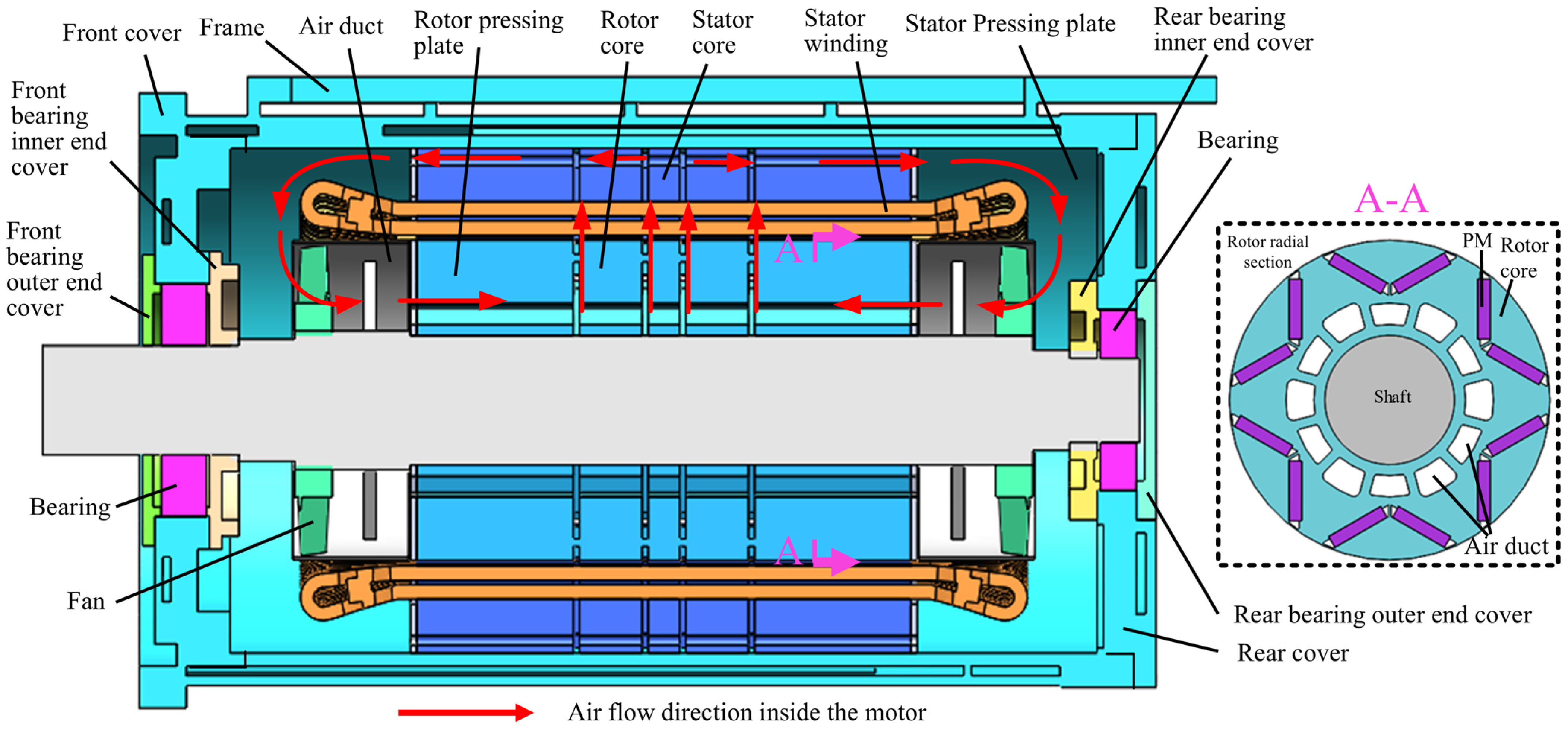
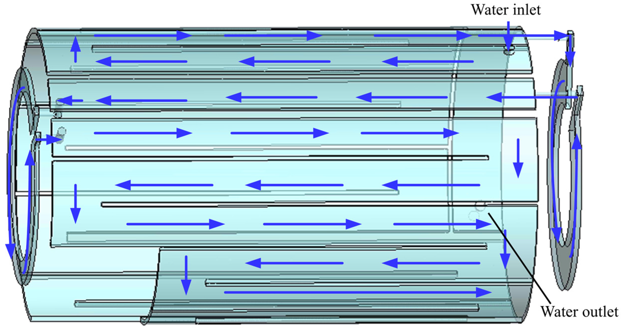
The motor was initially determined to adopt an explosion-proof water-cooled frame structure based on the characteristics of the abundant underground water resources in the mines. Drawing on the design experience from previous product developments, we found a significant temperature difference between the stator and rotor of the motor, with the rotor temperature being relatively high. If the motor is modified to a permanent magnet type without timely optimization and adjustment of the cooling structure, the risk of permanent magnet demagnetization will hinder the development and design of the motor towards a smaller volume and higher power density. To address the drawback of difficult rotor heat dissipation, this study proposes a novel cooling design scheme. A structural diagram of the permanent magnet motor is shown in Figure 2, and a structural diagram of the folded-back water channel is shown in Figure 3. In this study, a steady-state thermal analysis method was adopted to evaluate the final thermal state of the motor during continuous operation under duty cycle S1. The temperature field at the point where heat generation and heat dissipation reached equilibrium was simulated and calculated to verify that the temperature of each component remained below the material limit under the most severe continuous operation conditions.

2.2. Mathematical Model and Boundary Conditions

2.2.1. Mathematical Model

The modeling software used in this paper is SolidWorks (2016, Dassault Systèmes, Vélizy-Villacoublay, France), and the simulation software is ANSYS Fluent (19.1, ANSYS, Canonsburg, PA, USA). In practical engineering applications, the variation range of the densities of water and air is extremely small because the flow velocity in the motor fluid domain is much lower than the speed of sound. Therefore, both water and air can be regarded as incompressible fluids. Fluid flow in the motor fluid domain satisfies the mass, momentum, and energy conservation equations. The general expressions of the respective fundamental governing equations are as follows:
ρ ϕ t + div ρ υ ϕ = div Γ grad ϕ + s
where Φ denotes the general variable, ρ represents the fluid density in kg/m3, ν is the velocity vector, Γ is the generalized diffusion coefficient, and s is the source term.
The Renormalization Group (RNG) k-ε method is a model derived from the Navier–Stokes equations based on the renormalization group theory. The difference between the constant values in this model and those in the standard k-ε model was attributed to the introduction of additional variables. The mathematical transport equation for the dissipation rate of turbulent kinetic energy is derived from the exact turbulent dynamics equations and thus can better conform to the actual characteristics of turbulence. The RNG k-ε turbulence equations are as follows:
ρ d k d t = x i α k μ e f f k x i + G k + G b ρ ε Y M
ρ d k d t = x i α ε μ e f f ε x i + C 1 ε ε k ( G k + C 3 ε G b ) C 2 ε ρ ε 2 k R
where Gk denotes the turbulent kinetic energy k generated by the gradient of uniform velocity variation, Gb is the turbulent kinetic energy k produced by the buoyancy effect, YM is the factor that suppresses the propagation of fluctuations in compressible turbulence, and C, C, and C are assumed to be constant values. Based on the derivation of the Lagrangian mathematical formulas and experimental verification, these constant values were set as C = 1.44, C = 1.92, and C = 0.09; k and ε denote the reciprocals of the Prandtl numbers associated with the turbulent kinetic energy k and the dissipation rate ε, respectively.

2.2.2. Boundary Conditions

In this study, polyhedral meshing technology was used. Polyhedral meshes can achieve an optimal balance between tetrahedral and hexahedral mesh types. With the same number of meshes, polyhedral meshes usually yield more accurate solutions and are a common mesh type for handling CFD problems in motor modeling. Based on production experience and preliminary simulation verification, when the water flow rate is 3.6 m3/h, the number of meshes increases directly from approximately 30 million to approximately 80 million, whereas the variation in motor temperature increase is only approximately 1 °C. Therefore, controlling the mesh scale to approximately 60 million can achieve a balance between the calculation accuracy and solution efficiency, with the variation in the maximum winding temperature being less than 0.2%.
The numerical solver adopted a pressure-based steady-state solution, and the k-ω turbulence model was selected. This model was chosen because it can accurately resolve the flow in the near-wall region and precisely predict flow separation under adverse pressure gradients, both of which are crucial for accurately calculating the wall heat flux and potential flow separation, as these are the key physical processes that determine the temperature distribution of the motor. During the calculation process, the variation in the winding temperature was monitored, and it was ensured that the key physical quantities (winding temperature values) tended to stabilize after thousands of iterations. The residuals of all flow and energy equations converged to below 10−5, and the residual of the energy equation decreased to 10−8. The boundary condition was set to an outlet pressure of 0. In the steady-state simulation, the average heat source loading method was used to apply the corresponding heat sources to the stator, windings, rotor, and permanent magnets. Additionally, the Multiple Reference Frame method was adopted to handle the rotational effect of the rotor.
Because this study focused on the fluid flow and heat transfer characteristics in the cooling system, the fundamental assumptions and boundary conditions were specified as follows to simplify the solution process.
(1)
The losses in each part of the motor did not change with temperature and were applied as heat sources at the corresponding heat-generating locations. Stray losses were applied to the stator and rotor cores at a proportional ratio of 4:1, respectively.
(2)
The physical parameters of each medium in the water cooling system did not change with temperature.
(3)
The inlet boundary adopted a mass flow inlet, and inlet flow rates of 1.8, 2.4, 3, 3.6, 4.2, 4.8, and 5.4 m3/h were selected for verification. The outlet was set as a standard atmospheric pressure outlet, and both the initial water temperature and ambient temperature were set to 21 °C.
(4)
The motor was a rotating machine, and a multiple reference frame was adopted. The contact surfaces between the fluid and solid were set as no-slip wall boundaries. The RNG k-ε turbulence model was used, and an enhanced wall treatment was recommended.
During motor operation, the losses in each part act as heat sources. The total loss of the motor comprises iron, winding copper, permanent magnet eddy currents, and mechanical and stray losses. The iron loss, winding copper loss, and permanent magnet eddy current loss were obtained through finite element simulation calculations, whereas the mechanical and stray losses were derived from empirical calculations based on previous test results. The losses in each part of the motor are presented in Table 2.

3. Analysis of Motor Flow Field and Temperature Field

3.1. Analysis of Cooling Water Flow Performance

The velocity and flow resistance distributions in the cooling system were determined based on these assumptions and boundary conditions. The velocity and flow resistance distributions of the water channel at flow rates of 5.4 and 1.8 m3/h are shown in Figure 4a and 4b, respectively. The distribution patterns under the remaining flow rate conditions were consistent with these trends.
The velocity distribution is depicted in Figure 4. It can be observed from the figure that the velocity distribution in the frame water channel was relatively uniform, with no dead flow zones. Velocity mutations and vortex phenomena were observed only in the connection area with the front and rear end covers and were mainly caused by the sudden change in the cross-section and separation of the water flow from the boundary layer owing to the action of inertial force. This indicates that the overall pipeline design of the frame water channel was reasonable. In subsequent designs, the connection area between the frame and front/rear end covers should be prioritized for optimization to reduce or eliminate mutations and vortices.
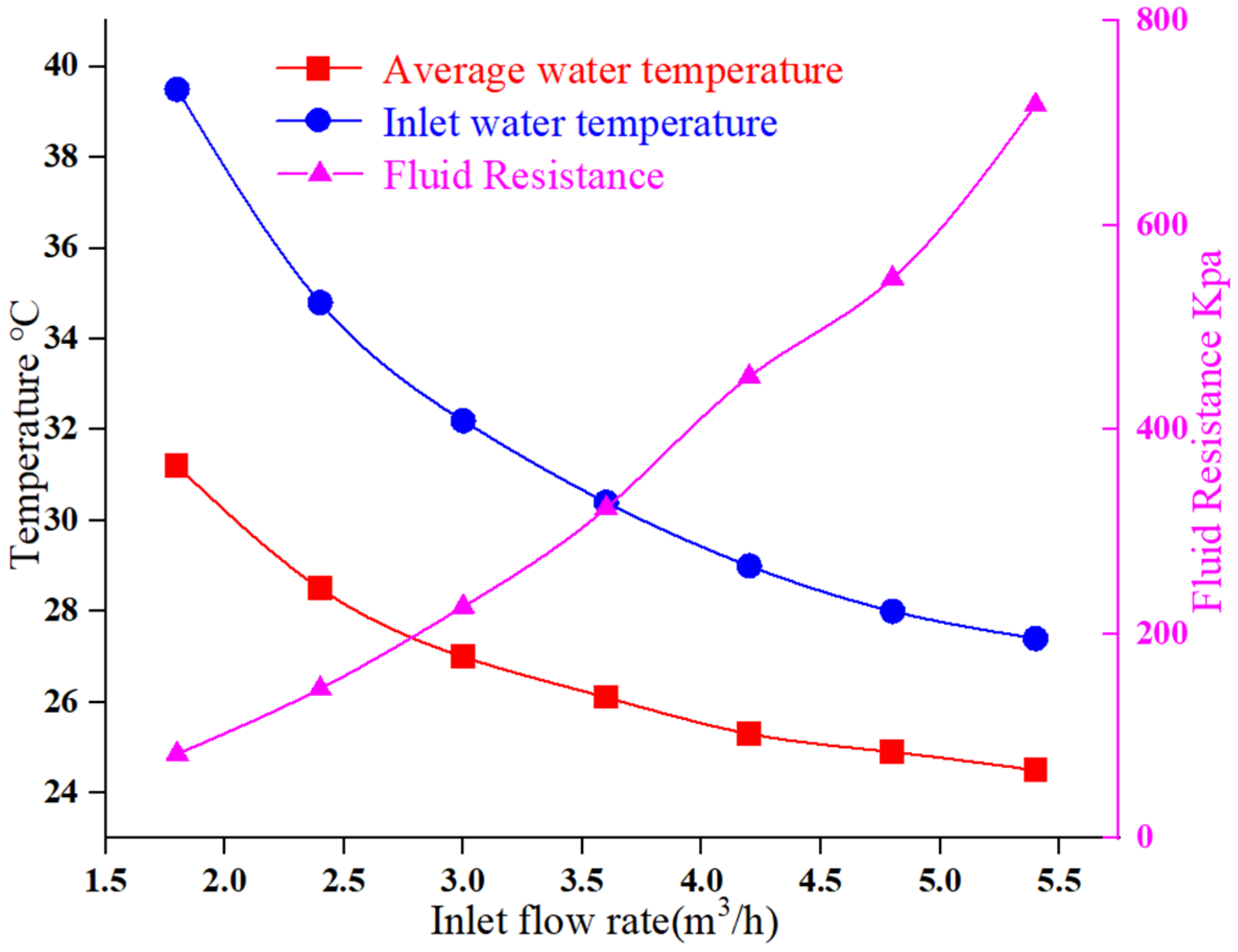
The pressure distribution diagram of the water channel under stable water flow is presented in Figure 5. The pressure at the water inlet was the highest and decreased gradually as the water flow rate increased, reaching its minimum value at the outlet. In addition, there are significant pressure mutations in the connection area between the frame water channel and the front/rear end covers, indicating that a sudden change in the cross-section leads to a sharp drop in the water flow pressure and causes an uneven local pressure distribution. In addition, the change in the water flow rate significantly affected the pressure drop between the inlet and outlet of the module. When the water flow rate was 5.4 m3/h, the pressure drop between the inlet and outlet was 718 kPa, and when the water flow rate was 1.8 m3/h, the pressure drop between the inlet and outlet was 83 kPa. Accordingly, the pressure loss in the water channel was reduced by 88.4%.

3.2. Analysis of Temperature Characteristics

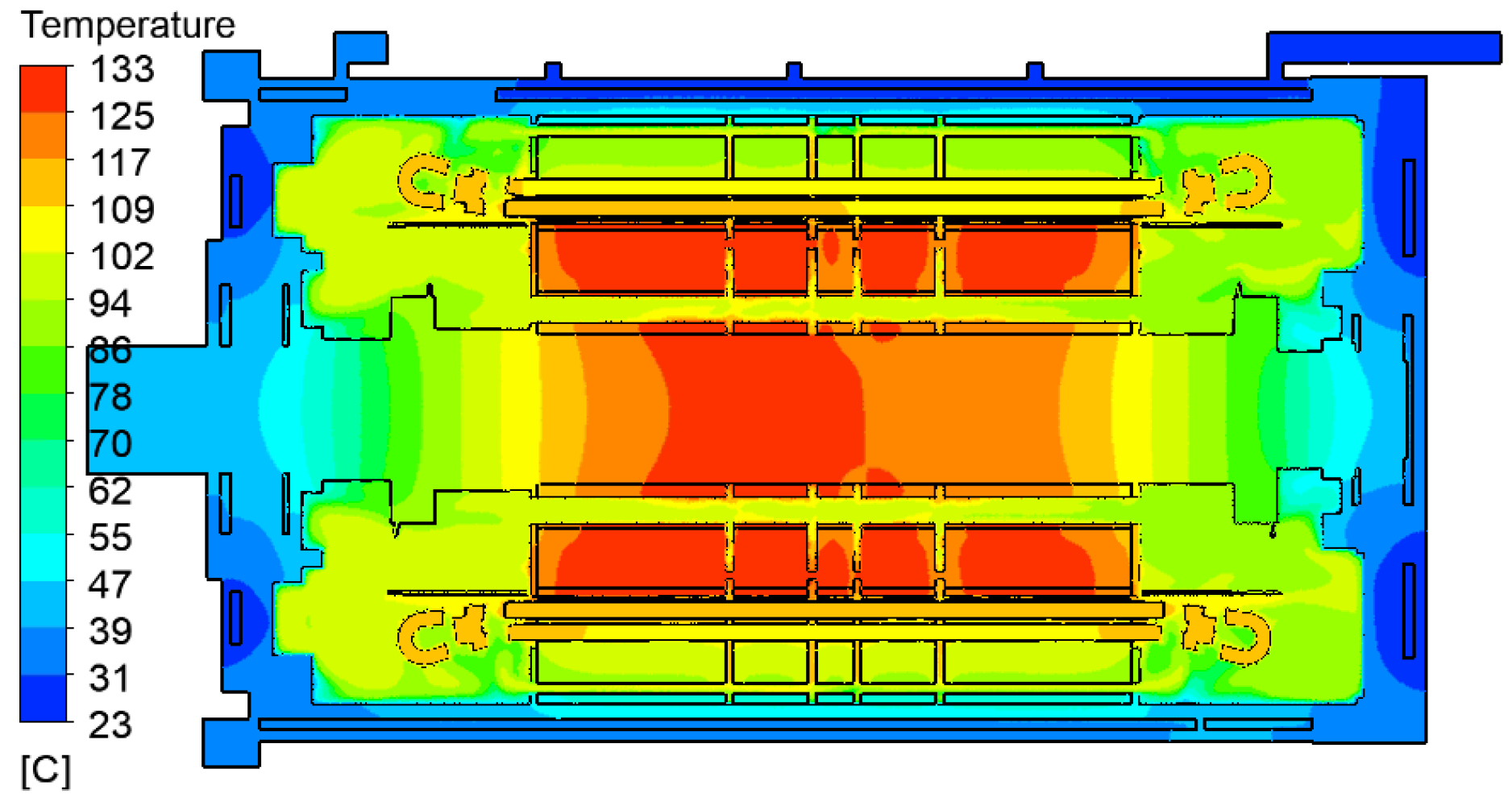
Different water flow rate conditions were set, and an overall temperature distribution diagram of the motor during operation was obtained using a fluid–structure interaction temperature field simulation. The temperature distribution in the meridional plane of the motor is illustrated in Figure 6. In the radial direction of the motor, the temperatures of the rotor core, stator core, and frame exhibited a gradient. Overall, the rotor exhibited the highest temperature, whereas the temperature near the motor housing was the lowest. The temperature gradually increased from the housing to the interior.
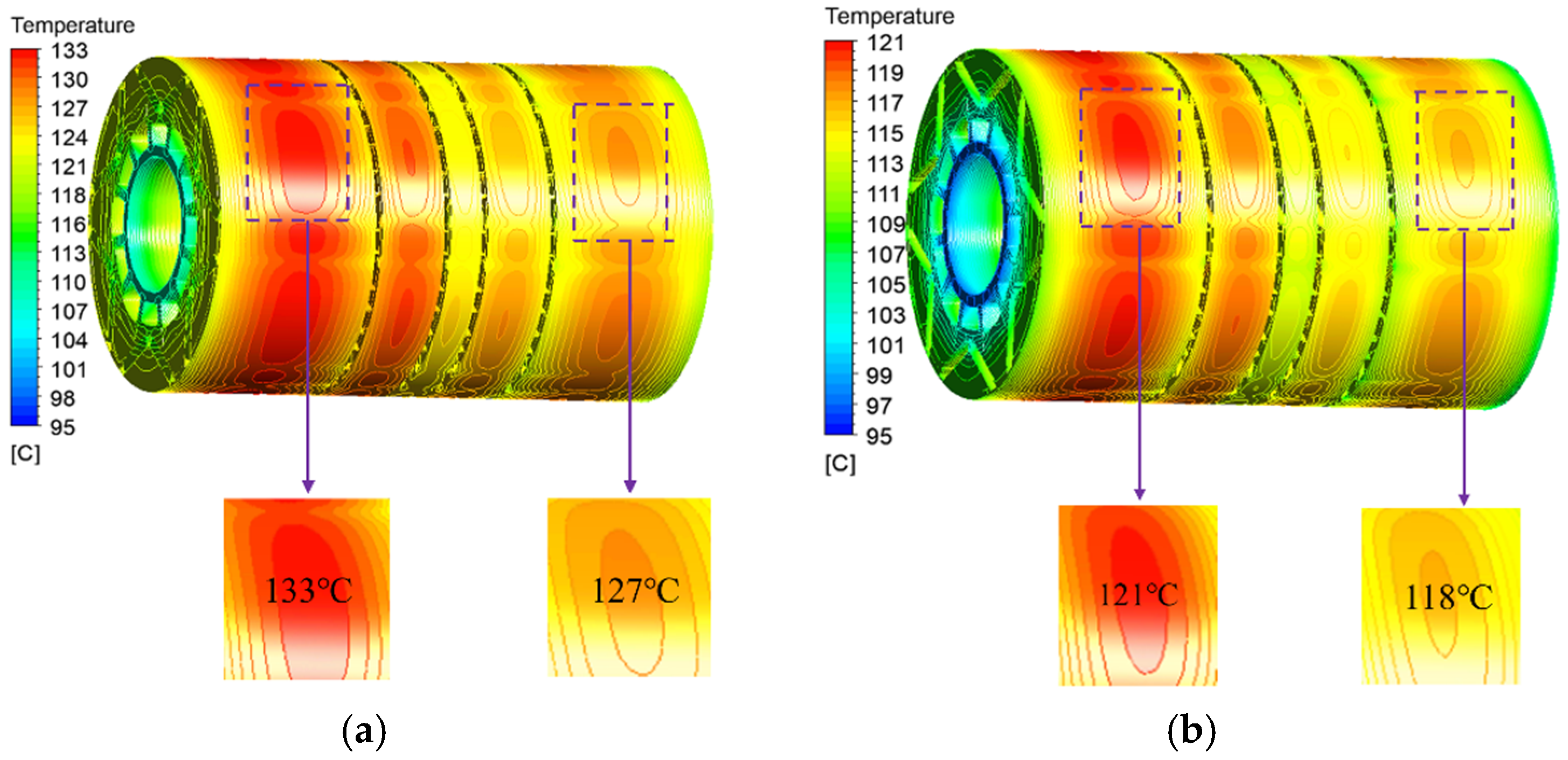
The temperature distribution of the rotor core is illustrated in Figure 7. As shown in Figure 7b, the temperature distribution in the circumferential direction of the rotor exhibited periodic characteristics related to the paired arrangement of permanent magnets. The high-temperature range in the area close to the permanent magnets was large, whereas that in the area between adjacent permanent magnets was small. As shown in Figure 7d, the high-temperature area of the permanent magnet was concentrated in its middle part. The heat conduction effect with the rotor core directly affects the temperature distribution of the core, which is consistent with the theoretical analyses. The rotor temperature distribution was affected as the inlet water flow rate increased. As shown in Figure 7c, the maximum rotor temperature decreased from 133 °C to 121 °C, with a reduction of 11 °C.
The temperature distributions on both sides of the rotor core are illustrated in Figure 8. As shown in the figure, the temperatures on both sides of the core were asymmetric, with a maximum temperature difference of 6 °C between the two sides of the core. This was mainly caused by the incomplete symmetry of the air path within the motor cavity. When the water flow rate increased to 5.4 m3/h, the temperature difference between the two ends decreased to 3 °C. This indicates that, under certain conditions, appropriately increasing the water flow rate can improve the temperature distribution inside the motor and ensure that the rotor operates in a uniform temperature environment.
The temperature distribution contours of the meridional section of the stator are illustrated in Figure 9. As the water flow rate increased, the red areas in the winding-temperature contour gradually faded, and the winding temperature tended to stabilize. The reduction in the motor winding temperature increase was mainly due to the increased flow velocity of the fluid in the water channel and enhanced turbulence intensity, which improved the convective heat transfer capacity. A relatively high water flow rate helps maintain the motor at a low operating temperature, extends the service life of the permanent magnet motor, and enhances the reliability of motor operation.
The relationships between the motor winding temperature, water channel convective heat transfer coefficient, and water flow rate are illustrated in Figure 10. As shown in the figure, as the water flow rate increased, the convective heat transfer coefficient of the water channel exhibited a linear increasing trend. In contrast, the motor winding temperature decreased gradually; it decreased rapidly in the early stage, and after the water flow rate reached 3.6 m3/h, the decreasing rate slowed down and eventually stabilized when the water flow rate reached 4.8 m3/h.

3.3. The Influence of Different Water Flow Rates on the Temperature of Motor Components and Pressure Drop

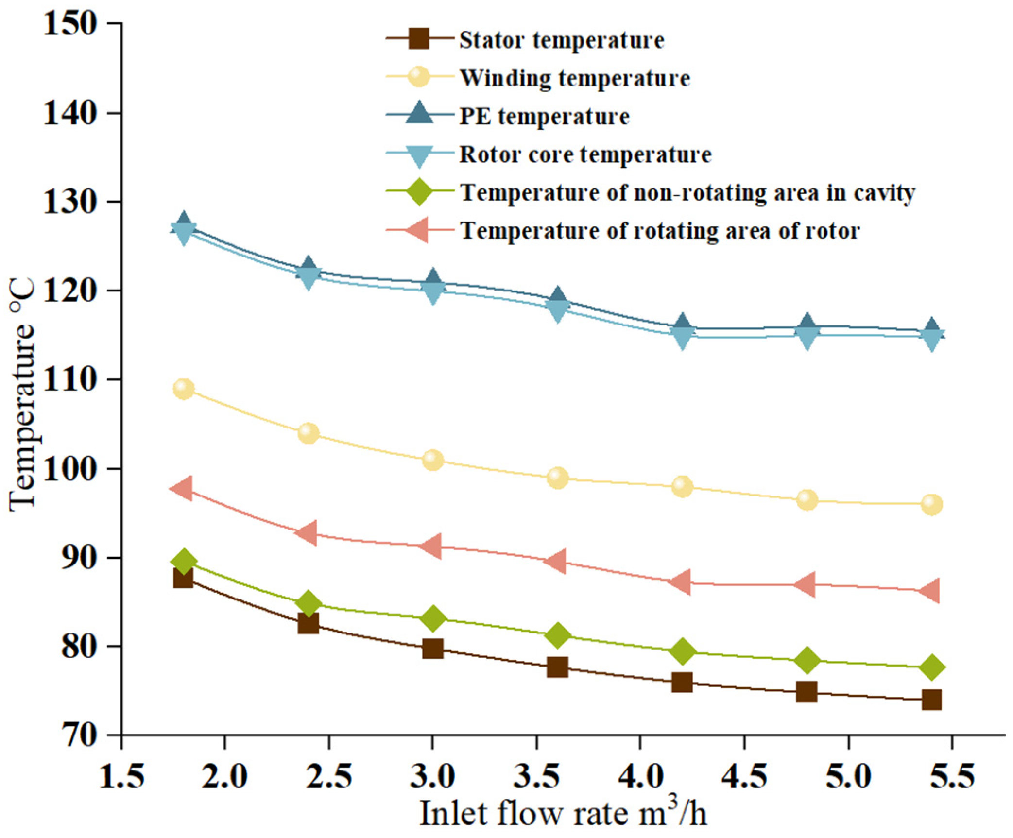
The influence of different water flow rates on the temperatures of the motor components is shown in Figure 11. As shown in the figure, as the water flow rate increased, the temperature of each motor component decreased, and the heat dissipation capacity of the water-cooled structure was enhanced, which is consistent with the fluid theory. m3/h, the temperature of each component decreased significantly; when the flow rate ranged from 1.8 to 3.6 m3/h, the temperature of each component decreased significantly; when the flow rate ranged from 3.6 to 5.4 m3/h, the temperature decrease tended to level off. The stator core had the lowest temperature because it was closer to the frame of the water channel. Meanwhile, within the studied water flow rate range of 1.8–5.4 m3/h, the temperature differences among the various motor components remained unchanged and were independent of the water flow rate.
The influence of different water flow rates on the outlet water temperature and pressure drop of the frame water channel is illustrated in Figure 12. As shown in the figure, as the water flow rate increased, the outlet water temperature and average temperature of the water channel decreased rapidly in the early stages. When the water flow rate exceeded 3.6 m3/h, the change in water temperature tended to level off. As the water flow rate increased, the rate of increase in the inlet-outlet pressure drop accelerated, and the required water pump power increased accordingly, which was consistent with the fluid theory analysis. When the water flow rate exceeded 3.6 m3/h, the pressure drop in the frame water channel increased significantly.
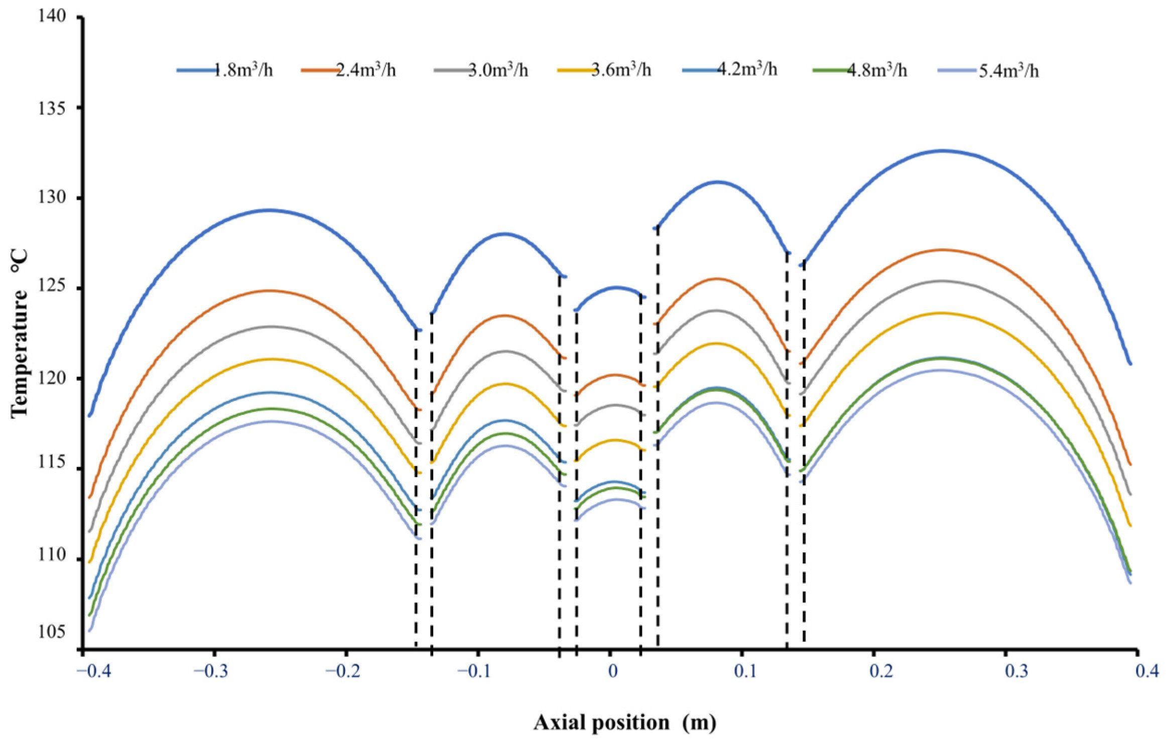
To further explore the variation law of the rotor surface temperature, a straight segment L with an axial length of 0.8 m on the rotor surface of the meridional plane in Figure 2 was selected as the sampling line, and the temperature variations at different flow rates were compared and analyzed. The axial temperature distribution on the rotor surface is shown in Figure 13, where the dashed black lines indicate the positions of the radial ventilation ducts.
As shown in the figure, the axial temperature on the rotor surface was symmetrically distributed with the middle of the rotor core (at an axial position of 0) as the boundary, exhibiting higher temperatures at both ends and lower temperatures at the middle. In addition, the temperature of each core segment exhibited periodic convex hull variations. This indicates that the radial ventilation ducts significantly affect the heat transfer of the rotor and that their surfaces can fully exchange heat with the cooling medium, generating an enhanced heat transfer effect. As the main pathway for heat transfer, the radial ventilation ducts further improve the convective heat transfer performance of the motor. Additionally, the results revealed the influence of the water flow rate on the rotor surface temperature: when the flow rate was 3.6 m3/h, the rotor temperature could be efficiently reduced.

4. Discussion

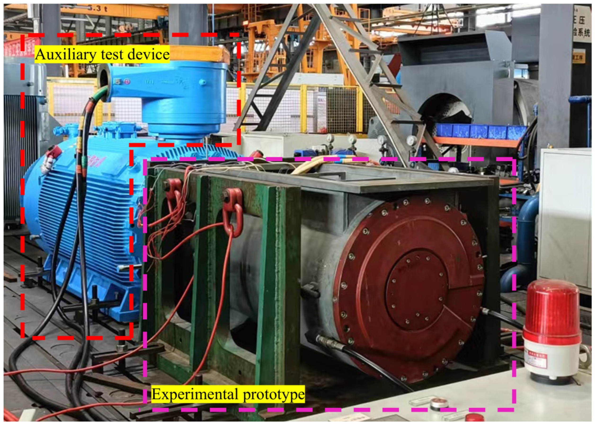
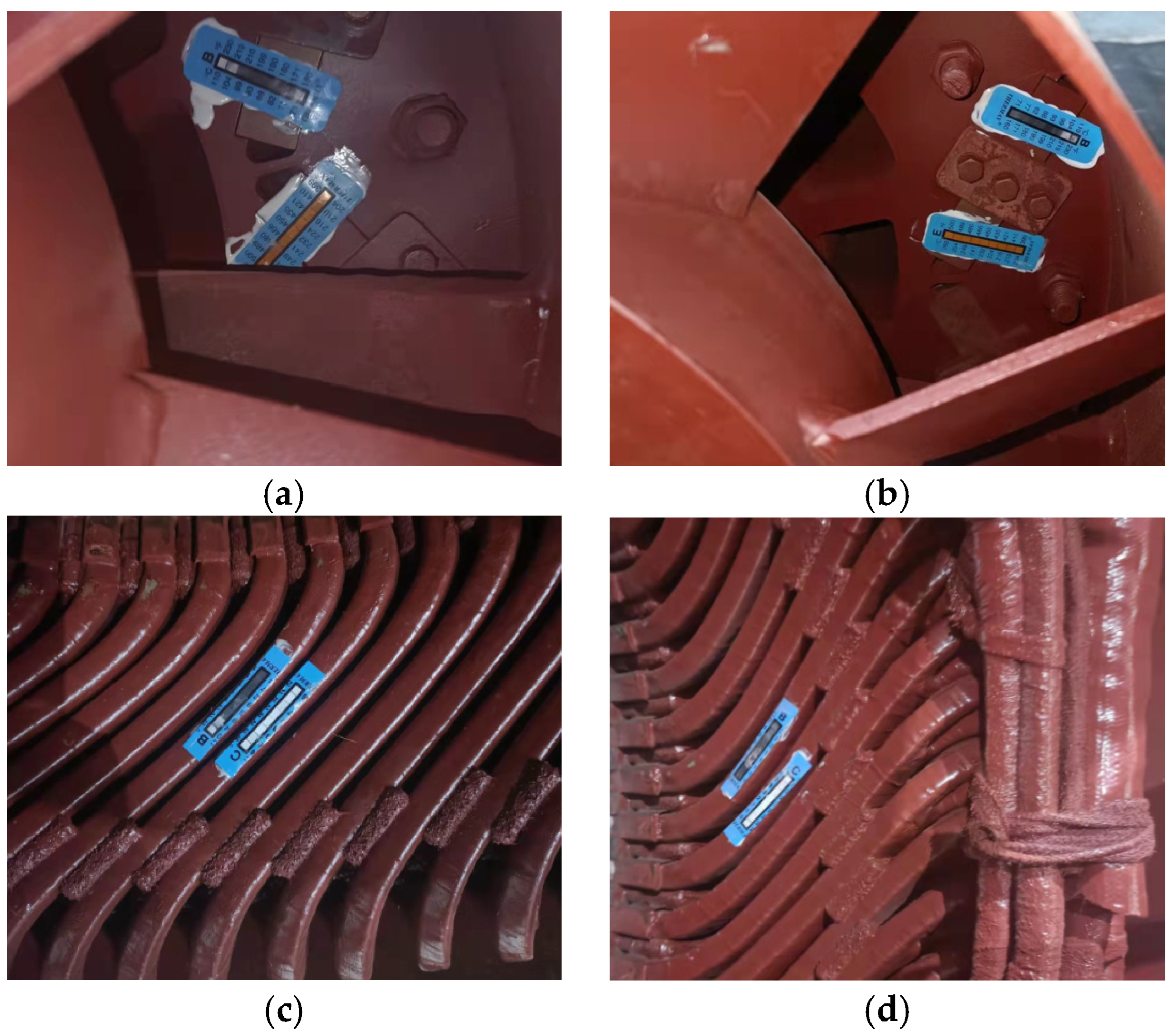
To verify the accuracy of the motor temperature field simulation results, a temperature rise test was conducted under the working condition of a water flow rate of 3.6 m3/h. The motor temperature was measured using pre-embedded thermocouples, the local temperature of the rotor was measured using thermally sensitive test papers, and the inlet and outlet water temperatures were measured using sensors. The prototype used for the on-site testing is shown in Figure 14. The inlet water temperature during the test was 21 °C, and the motor temperature increase calculated based on the thermal resistance method was 76 K. Compared with the simulation result of 78 K, the error was 2.7%. The local temperature at the test paper measurement points of the rotor after disassembling the motor is shown in Figure 15, with a maximum error of 4.8%. As presented in Table 3, all relative errors were within the allowable engineering range, verifying the rationality of the numerical simulation method.

5. Conclusions

In this study, heat dissipation calculations on the flow and heat transfer characteristics of a 1600 kW mining flameproof integrated variable-frequency permanent magnet motor were conducted, and experimental tests were performed. The following conclusions were drawn:
  • Within the water flow rate range of 1.8–5.4 m3/h, the temperature difference between the various components of the motor remained constant and was independent of the water flow rate. The temperature in the stator region was approximately 20 °C lower than that in the rotor region. The new cooling scheme can transfer heat to the low-temperature region of the stator through axial and radial ventilation ducts for effective heat dissipation, thereby solving the problem of difficult heat dissipation in the rotor.
  • The simulation results showed that changes in the inlet flow rate of the cooling water led to differences in the motor-temperature distribution. As the water flow rate increased, the overall temperature of the motor decreased; however, the temperature reduction in the permanent magnet was limited, resulting in low cooling efficiency. When the cooling water flow rate was 3.6 m3/h, the pressure loss in the water channel was reduced by 54.9%. The winding temperature differed by only 3 °C compared with that at the maximum water flow rate of 5.4 m3/h, indicating high cooling efficiency. Considering the flow rate and pressure requirements of the water supply system, a cooling water flow rate of 3.6 m3/h can achieve optimal cooling performance under the premise of minimizing costs, thereby improving the operational economy and reliability of the motor.
  • Compared with the experimental test data, the maximum temperature error at the measurement points of the winding ends and rotor was 4.8%. Additionally, the motor temperature increase obtained from the simulation was 78 K, with an error of 2.7% compared with the experimental result. These results verify the effectiveness and accuracy of the proposed approach.

Author Contributions

Conceptualization, X.W. (Xiaojun Wang), G.T. and Q.L.; methodology, X.W. (Xiaojun Wang), G.T. and Q.L.; validation, X.W. (Xiaojun Wang), G.T., L.Y. and K.Z.; data curation, K.Z., Q.L., L.Y. and G.L.; writing—original draft preparation, X.W. (Xiaojun Wang), G.T., Q.L. and K.Z.; writing—review and editing, K.Z., X.W. (Xuandong Wu) and L.Y.; supervision, X.W. (Xiaojun Wang), X.W. (Xuandong Wu), L.Y., G.T. and G.L.; project administration, L.Y., G.L. and X.W. (Xuandong Wu); funding acquisition, L.Y. and G.L. All authors have read and agreed to the published version of the manuscript.

Funding

This research was funded by Key R&D and Promotion Special/Tackling Key Problems in Science and Technology in Henan Province, China (grant No. 242102111173, 252102241063, 242102220079); Henan Province Science and Technology Research and Development Joint Fund (Industrial Category) (grant No. 202324119); Key Scientific Research Fund of Pingdingshan University (grant No. PXY-JXZDXK-202306, 2023-JYZD01).

Data Availability Statement

All relevant data can be obtained in this article.

Conflicts of Interest

Authors Xiaojun Wang and Xuandong Wu employed by the company Wolong Electric Nanyang Explosion Protection Group Co., Ltd. The remaining authors declare that the research was conducted in the absence of any commercial or financial relationships that could be construed as a potential conflict of interest.

References

  1. Tang, R.Y.; Zhao, Q.; Zhou, T. Rare earth permanent magnet electrical machines stepping a new period of rapid development. J. Shenyang Univ. Technol. 2011, 33, 1–8. [Google Scholar]
  2. Zhang, F.G.; Du, G.H.; Wang, T.Y.; Liu, G.W. Review on Development and Design of High Speed Machines. Trans. China Electrotech. Soc. 2016, 31, 1–18. [Google Scholar]
  3. Dong, J.N.; Huang, Y.K.; Jin, L.; Lin, H.Y. Review on High Speed Permanent Magnet Machines Including Design and Analysis Technologies. Proc. CSEE 2010, 30, 78–83. [Google Scholar]
  4. Yang, M.; Zhao, L.H.; Ma, J.Z.; He, Z.Q.; Li, Y.X. Investigation of Distributed Winding Topologies on Surface-Mounted Permanent Magnet Machines. Small Spec. Electr. Mach. 2011, 50, 14–21. [Google Scholar]
  5. Hou, H.W.; Qin, Z. Research and analysis of temperature field on mine permanent magnet direct drive motor. Coal Sci. Technol. 2021, 49, 219–224. [Google Scholar]
  6. Xie, B.C.; Zhang, Y.; Wang, J.Q.; Liang, B.X.; Zhang, F.G. An efficient multidisciplinary design research for the integrated low speed permanent magnet motor system based on analytical and numerical hybrid analysis. Energy Rep. 2022, 8, 199–208. [Google Scholar] [CrossRef]
  7. Wei, Q.; Feng, G.H.; Zhang, B.Y. Cooling system of direct drive PMSM for mining belt conveyor. J. Mech. Electr. Eng. 2019, 36, 873–878. [Google Scholar]
  8. Xia, W.G. Design of Water-Cooling System for Mine-Used Flameproof Permanent Magnet Synchronous Motor. New Technol. New Prod. China 2020, 3, 12. [Google Scholar]
  9. Han, J.D.; Sun, P.; Zhu, L.B.; Lu, Y.P.; Zhu, J.N. 3D CFD thermal calculation for a vertical asynchronous motor with a squirrel-cage rotor. Electr. Mach. Control 2020, 24, 55–61. [Google Scholar]
  10. Karakatsanis, T.S. Optimization and Performance Evaluation of PM Motor and Induction Motor for Marine Propulsion Systems. Appl. Syst. Innov. 2025, 8, 58. [Google Scholar] [CrossRef]
  11. Cao, Z.B.; Li, W.L.; Zhang, X.C.; Fan, Y.; Zeng, J.J. Influence of single/dual ventilation path on fluid field and temperature field of HVLSSR-PMSM with air-cooled hybrid ventilation systems. Energies 2018, 11, 1343. [Google Scholar] [CrossRef]
  12. Wang, S.W.; Jiang, M.; Zhu, B.L.; Liu, M.L. Three-Dimensional Temperature Field Investigation of Variable-Frequency Adjustable-Speed Water-Cooled Permanent Magnet Synchronous Motor for Vehicle. Electr. Mach. Control Appl. 2017, 231, 43–51. [Google Scholar]
  13. Li, C.; Huang, F.C.; Wang, Y.Q. An applicable real-time thermal model for temperature prediction of permanent magnet synchronous motor. J. Syst. Control Eng. 2017, 231, 43–51. [Google Scholar] [CrossRef]
  14. Du, G.H.; Xu, W.; Zhu, J.G.; Huang, N. Power Loss and Thermal Analysis for High-Power High-Speed Permanent Magnet Machines. IEEE Trans. Ind. Electron. 2020, 67, 2722–2733. [Google Scholar] [CrossRef]
  15. Wu, S.N.; Hao, D.Q.; Tong, W.M. Temperature Field Analysis of Mine Flameproof Outer Rotor Permanent Magnet Synchronous Motor with Different Cooling Schemes. CES Trans. Electr. Mach. Syst. 2022, 6, 162–169. [Google Scholar] [CrossRef]
  16. Sebastien, S.; Kevin, B.; Emily, C.J.; Sreekant, N.; Gilberto, M.; Satish, K.; Yogendra, J. Validation and Parametric Investigations of an Internal Permanent Magnet Motor Using a Lumped Parameter Thermal Model. J. Electron. Packag. 2022, 144, 021114. [Google Scholar] [CrossRef]
  17. Zhang, W.; Li, G.J.; Zhu, Z.Q.; Ren, B.; Chong, Y.C. Semi-flooded cooling for high torque density modular permanent magnet machines. IET Electr. Power Appl. 2024, 18, 756–765. [Google Scholar] [CrossRef]
  18. Nguyen, M.D.; Woo, J.H.; Shin, H.S.; Lee, Y.K.; Lee, H.K.; Shin, K.H.; Phung, A.T.; Choi, J.Y. Thermal analysis and experimental verification of permanent magnet synchronous motor by combining lumped parameter thermal networks with analytical method. AIP Adv. 2023, 13, 025140. [Google Scholar] [CrossRef]
  19. Zhu, E.H.; Liang, Y.P.; He, L.L. Research on Temperature Rise of the Large-Capacity Air-Cooled Synchronous Condenser. J. Electr. Eng. Technol. 2025, 20, 1679–1689. [Google Scholar] [CrossRef]
  20. Gao, L.L.; Liu, X.; Liu, H. Analytical Calculation of Magnetic Field and Temperature Field of Surface Mounted Permanent Magnet Synchronous Motor. J. Electr. Eng. Technol. 2025, 20, 2249–2262. [Google Scholar] [CrossRef]
  21. Yi, Y.L.; Ma, S.; Zhang, B.; Feng, W. Application of High Efficiency and High Precision Network Algorithm in Thermal Capacity Design of Modular Permanent Magnet Fault-Tolerant Motor. Energies 2025, 18, 3967. [Google Scholar] [CrossRef]
  22. Liu, H.; Chen, W.W.; Liu, D.; Chu, N.N. Design and Analysis of Cooling System for Dual-Stator Permanent Magnet Wind Power Generator. J. Electr. Eng. Technol. 2025, 20, 4135–4147. [Google Scholar] [CrossRef]
  23. Cao, L.F.; Fan, X.G.; Li, D.W.; Qu, R.H.; Liu, J.Y. Semi-Analytical and Efficient Calculation Method of Eddy Current Loss in Windings of Permanent Magnet Machines Based on Fast Finite Element Method. Trans. China Electrotech. Soc. 2023, 38, 153–165. [Google Scholar]
  24. Shi, W.; Luo, K.C.; Zhang, Z.Y. On-Line Temperature Estimation of Permanent Magnet Motor Based on Lumped Parameter Thermal Network Method. Trans. China Electrotech. Soc. 2023, 38, 2686–2697. [Google Scholar]
  25. Wu, Y.; Zhang, Z.F.; Ping, J.Q. New Type Water Cooling Structure Design and Temperature Field Analysis of High Power Density Axial Flux Permanent Magnet Motor. Proc. CSEE 2021, 41, 8295–8305. [Google Scholar]
  26. Han, X.Y.; Zhang, H.W.; Xu, X.; Lan, Y.H. Design of Cooling System for Amorphous Alloy Axial Flux Permanent Magnet Motor Based on Computational Fluid Dynamics. Trans. China Electrotech. Soc. 2017, 32, 189–197. [Google Scholar]
  27. Chen, L.X.; Liu, D.; Zhang, C.; Sun, N. Design and analysis of ultra-high speed permanent magnet motor cooling system based on multi-physical field. Electr. Mach. Control 2023, 27, 113–123. [Google Scholar]
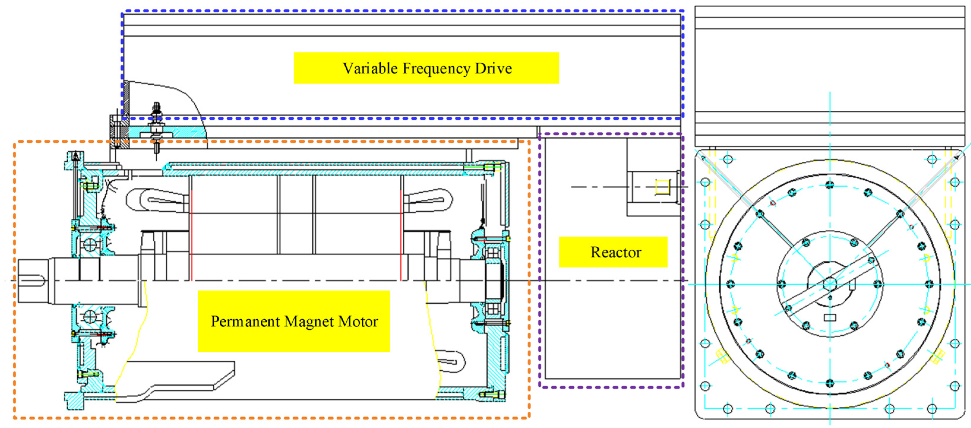
Figure 1. Schematic Diagram of the Variable Frequency Integrated Unit Structure.
Energies 18 05369 g001
Figure 2. Schematic Diagram of the Permanent Magnet Motor Structure. The pink arrow indicates a partial removed section view of the section view in engineering drawing, which corresponds to A-A in the figure.
Energies 18 05369 g002
Figure 3. Reflux-type Water Channel Structure. The blue arrow here indicates the direction of water flow in the pipeline.
Energies 18 05369 g003
Figure 4. Velocity Distribution Diagrams of Water Flow Under Different Inlet Flow Rates: (a) At a flow rate of 5.4 m3/h; (b) At a flow rate of 1.8 m3/h.
Energies 18 05369 g004
Figure 5. Flow Resistance Distribution Diagrams of Water Flow Under Different Inlet Flow Rates: (a) The water flow rate is 5.4 m3/h; (b) The water flow rate is 1.8 m3/h; (c) Relationship Between Water Flow Group and Flow Rate Variation.
Energies 18 05369 g005
Figure 6. Temperature Distribution Map of the Meridional Cross-Section (The water flow rate is 1.8 m3/h).
Energies 18 05369 g006
Figure 7. Temperature Distribution Map of the Rotor (The water flow rate is 5.4 m3/h), they should be listed as: (a) temperature distribution map of the meridional cross-section; (b) Temperature Distribution Map of the Rotor Core; (c) Relationship Between Rotor Temperature and Flow Rate Variation; and (d) Temperature Distribution Map of the Permanent Magnet.
Energies 18 05369 g007
Figure 8. The temperature Distribution Map of the Rotor Core should be listed as follows: (a) the water flow rate is 1.8 m3/h; (b) the water flow rate is 5.4 m3/h.
Energies 18 05369 g008
Figure 9. Temperature Distribution Contour of the Stator.
Energies 18 05369 g009
Figure 10. Relationships Between Motor Winding Temperature, Water Channel Convective Heat Transfer Coefficient, and Water Flow Rate.
Energies 18 05369 g010
Figure 11. Relationship between the Average Temperature of Each Motor Component and Water Flow Rate Variation.
Energies 18 05369 g011
Figure 12. Relationship between Water Temperature, Fluid Resistance, and Water Flow Rate Variation.
Energies 18 05369 g012
Figure 13. Axial Temperature Distribution on the Rotor Surface.
Energies 18 05369 g013
Figure 14. On Site Testing Prototype.
Energies 18 05369 g014
Figure 15. Temperature at the Test Paper Measurement Points: (a) Temperature of the Rotor Measuring Point at the Non-Shaft Extension End; (b) Temperature of the Rotor Measuring Point at the Shaft Extension End; (c) Measuring Point at the Winding End of the Non-Shaft Extension End; (d) Measuring Point at the Winding End of the Shaft Extension End.
Energies 18 05369 g015
Table 1. Basic Parameters of the Permanent Magnet Motor.
ParameterValue
Rated Power/kW1600
Rated Voltage/V3300
Rated Speed/rpm1500
Number of Stator Slots72
Air Gap/mm2.5
Table 2. Motor Loss Data.
Stator Winding Loss (W)8756
Stator Core Loss (W)15,138
Rotor Core Loss (W)1744
Permanent Magnet Loss (W)282
Mechanical Loss (W)2419
Stray Loss (W)8000
Table 3. Comparison Between Simulation and Experiment.
Temperature of the Measuring Point at the Winding End of the Shaft Extension EndTemperature of the Measuring Point at the Winding End of the Non-Shaft Extension EndTemperature of the Rotor Measuring Point at the Shaft Extension EndTemperature of the Rotor Measuring Point at the Non-Shaft Extension End
Simulation (℃)114109103102
Experimental Value (℃)1101049999
Error (%)3.64.843
Disclaimer/Publisher’s Note: The statements, opinions and data contained in all publications are solely those of the individual author(s) and contributor(s) and not of MDPI and/or the editor(s). MDPI and/or the editor(s) disclaim responsibility for any injury to people or property resulting from any ideas, methods, instructions or products referred to in the content.