Article

A Tie-Line Fault Ride-Through Strategy for PV Power Plants Based on Coordinated Energy Storage Control

1
Anji Power Supply Company of State Grid Zhejiang Electric Power Co., Ltd., Huzhou 313300, China
2
Zhejiang Anji General Electric Power Development Co., Ltd., Huzhou 313300, China
3
State Grid Huzhou Electric Power Supply Company, Huzhou 313000, China
4
Yangtze Delta Region Institute (Huzhou), University of Electronic Science and Technology of China, Huzhou 313001, China
*
Author to whom correspondence should be addressed.
Energies 2025, 18(20), 5335; https://doi.org/10.3390/en18205335
Submission received: 18 September 2025 / Revised: 2 October 2025 / Accepted: 5 October 2025 / Published: 10 October 2025
(This article belongs to the Section A1: Smart Grids and Microgrids)

Abstract

Unplanned islanding and off-grid issues of photovoltaic (PV) power stations caused by tie-line faults have seriously undermined the power supply reliability and operational stability of PV plants. Furthermore, it takes a relatively long time to restore normal operation after an off-grid event, leading to substantial power losses. To address this problem, this paper proposes a tie-line fault ride-through control strategy based on the coordinated control of on-site energy storage units. After a fault on the tie-line occurs, the control mode of PV inverters is switched to achieve source–load balance, and the control mode of energy storage inverters is switched to VF control mode, which supports the stability of voltage and frequency in the islanded system. Subsequently, the strategy coordinates with the tie-line recloser device to perform synchronous checking and grid reconnection. Simulation results show that, for transient tie-line faults, the proposed method can achieve stable control of the islanded system and grid reconnection within 2 s after a fault on the tie-line occurs. It successfully realizes fault ride-through within the operation time limit of anti-islanding protection, effectively preventing the PV plant from disconnecting from the grid. Finally, a connection scheme for the control strategy of a typical PV plant is presented, providing technical reference for on-site engineering.

1. Introduction

With the development of new electricity system, the integration of renewable energy power plants into the grid has been increasing significantly. The capabilities of these plants for low-voltage ride-through (LVRT), high-voltage ride-through (HVRT), and con-tinuous fault ride-through (FRT) have also been increasingly enhanced, providing strong support for the secure and stable operation and power supply reliability of these plants [1,2]. However, large-scale disconnections of renewable energy plants still occur from time to time. In particular, when a tie-line fault occurs and protection devices operate to trip circuit breakers, the renewable energy plant and its auxiliary load form an islanded system [3,4,5]. Due to power imbalance within the island, voltage and frequency rapidly deviate from their rated values, triggering voltage/frequency protection and anti-islanding protection operations, which ultimately leads to the disconnection of all inverters in the plant and failure to achieve fault ride-through. Consequently, after a tie-line fault causes a renewable energy plant to disconnect, it takes a considerable amount of time after the fault is cleared to restore normal operation through manual intervention. This results in significant pow-er loss and severely impacts the system’s power supply reliability and operational stability.
Under the current control strategy, when a tie-line fault occurs at a PV power plant, the plant will initially operate off-grid and then completely disconnect and shut down after the protection devices of the PV and energy storage inverters operate. This results in the plant being unable to reconnect to the grid for an extended period. In the case of a permanent tie-line fault, the tie-line protection operates to trip the circuit breakers, causing the PV plant to form an island. After 2 s, the anti-islanding protection activates, disconnecting the PV inverters. This loss of power generation is necessary to sacrifice for the security and stability of the main grid. However, for transient tie-line faults, if stable islanded operation of the PV plant can be achieved before the anti-islanding protection operates (i.e., within 2 s after the fault occurrence), ensuring that the PV and energy storage inverters do not trip, this provides a feasible condition for plant reconnection. Then, through synchronism-check reclosing of the tie-line device, the plant can be re-synchronized and reconnected to the grid. This allows the PV plant to ride through the transient tie-line fault without inverter disconnection, significantly enhancing the power supply reliability of the plant and the stability of the system. Currently, research in this specific area remains scarce.
Reference [6] analyzes 11 large-scale renewable energy disconnection incidents that occurred in the United States, Australia, and the United Kingdom between 2016 and 2023. It summarizes four main causes for renewable power plant disconnections: (1) insufficient support capability of weak AC systems for high-penetration renewable energy integration; (2) lack of comprehensive standards and specifications for renewable energy control strategies and configuration principles; (3) grid faults triggering conventional protection (e.g., under/over frequency and voltage protection) of renewable energy systems; and (4) external factors such as extreme weather conditions causing failures of renewable energy equipment. Statistically, these four causes account for 26.5%, 47.1%, 23.5%, and 2.9% of the incidents, respectively. This indicates that disconnections caused by inadequate renewable energy control strategies constitute the highest proportion.
Reference [7] addresses the challenge of maintaining frequency and voltage stability in islanded microgrids under conventional control methods. It proposes an improved stable operation control strategy driven by both enhanced virtual synchronous generator (VSG) and droop control mechanisms. Reference [8] addresses the issue that traditional virtual inertia control cannot simultaneously mitigate system frequency deviations and ensure recovery performance. It proposes a frequency active support control strategy for islanded microgrids with parallel virtual synchronous generator (VSG) systems, based on fuzzy adaptive control of virtual inertia. This strategy takes into account the dynamic processes during both the frequency deviation and recovery stages, effectively mitigating control conflicts between these two phases. Reference [9] addresses the challenges in islanded microgrids with a high penetration of renewable energy: the reduced proportion of traditional synchronous generators leads to declining overall system inertia, and conventional control strategies fail to effectively regulate frequency and voltage under such low-inertia conditions. To enhance the dynamic stability of frequency and voltage in islanded microgrids, this study proposes a model predictive control (MPC)-based frequency and voltage control strategy for energy storage systems configured as virtual synchronous generators (VSGs).
Reference [10] investigates the issue of static voltage stability during the steady-state low-voltage ride-through (LVRT) process under grid fault conditions in renewable energy systems. The analysis focuses on voltage instability problems resulting from inappropriate active and reactive current injection strategies during faults. Reference [11] focuses on the issue that wind, photovoltaic (PV), and energy storage power sources in renewable energy bases lacking strong grid support are highly susceptible to instability due to voltage sags, adversely affecting the overall fault ride-through (FRT) capability of the base. Based on differences in the transient control strategies of power converters within the renewable energy systems, the analysis identifies that key factor leading to control instability in grid-following renewable energy sources and grid-forming energy storage (which maintains grid-forming control during faults) under grid faults include DC-link voltage fluctuations and power angle instability. Furthermore, it derives calculation expressions for the maximum reactive power that grid-following and grid-forming converters can inject within their respective stable operating ranges. A coordinated control strategy for maximum reactive power compensation is proposed for wind farms, PV power plants, and energy storage systems under different active power output conditions. In contrast, Reference [12] approaches the problem from the perspective of automatic reclosing. It calculates the boundary conditions for arc self-extinction under the transient output of PV systems during faults. By controlling the transient output of PV systems during a fault, the method aims to prevent reclosing failure caused by the inability of the arc to extinguish in transient faults. An adaptive reclosing method based on the control and capacity calculation of PV transient output during faults is proposed. Reference [13] addresses the limitations of traditional low-voltage ride-through (LVRT) strategies, such as voltage and current exceeding limits, frequency instability, and lack of coordination among multiple inverters. It proposes a two-stage coordinated fault ride-through control strategy for multiple PV power sources. Reference [14] addresses a limitation of traditional Automatic Transfer Schemes (ATS): their activation criteria based on “dead bus voltage and dead incoming current” often force the disconnection of renewable sources as a prerequisite for ATS operation in renewable energy plants. This requirement lowers renewable energy utilization and compromises power supply reliability. To overcome this, the proposed scheme utilizes station-integrated energy storage systems controlled with Virtual Synchronous Generator (VSG) technology. By considering different levels of source–load power matching and the operational sequence of various system modules, it introduces a rapid ATS strategy that incorporates coordinated energy storage control. Reference [15] focuses on distribution networks with high penetration of distributed energy resources at their feeder ends. It proposes a fault self-healing control strategy for photovoltaic (PV) power plants based on coordinated regulation from energy storage systems.
The studies mentioned above, along with relevant international research, provide detailed analyses from perspectives including the causes of PV plant disconnection incidents, voltage stability control during low-voltage ride-through (LVRT), grid-forming energy storage control, adaptive reclosing strategies, and rapid automatic transfer schemes (ATS) [16,17,18,19,20,21,22]. These works thoroughly investigate the key factors leading to PV plant disconnections and explore feasible fault ride-through (FRT) control strategies. However, current research still lacks a specific FRT strategy tailored for tie-line fault scenarios in PV power plants. Notably, no effective solution has been proposed that enables PV plants to be rapidly reclosed to the grid after transient tie-line fault clearance.
Based on this, this paper focuses on leveraging the existing small-capacity energy storage system (ESS) in PV power plants through coordinated control c between ESS and PV generation. The goal is to achieve stable islanded operation of the PV plant after a transient tie-line fault, and to coordinate with reclosing devices to resolve the challenge of rapid re-synchronization. This approach aims to realize tie-line fault ride-through (FRT) for PV power plants, thereby preventing permanent plant disconnection and enhancing the system’s economic efficiency and operational stability.

2. Analysis of Tie-Line Faults in PV Power Plants

2.1. Tie-Line Fault

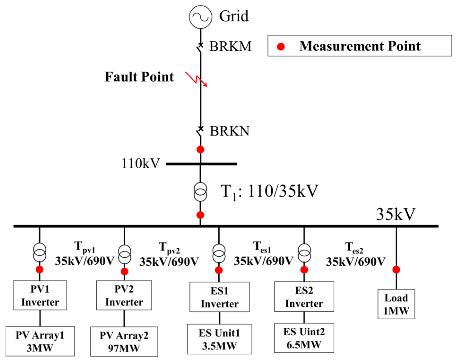
PV power plants are typically connected to the grid via dedicated tie-lines, as shown in Figure 1. All PV arrays are integrated into the plant through their inverters and transformers. Each PV branch is equipped with a circuit breaker (BRK1, BRK2, etc.) to control the startup, grid connection, shut down, and fault disconnection processes. In China, for PV power plants connected at the 110 kV voltage level, either a single-circuit or double-circuit tie-line configuration can be adopted for grid interconnection.
Photovoltaic (PV) inverters operate in Maximum Power Point Tracking (MPPT) mode to generate power into the grid. The PV power plant is connected to the grid through step-up transformers and dedicated tie-lines. Differential protection is normally installed for the tie-line at circuit breakers BRKM and BRKN. The auto-reclosing of circuit breakers BRKM and BRKN is initiated by protection operation of the tie-line. The circuit breaker BRKM is normally closed on dead-line. After circuit breaker BRKM is closed, circuit breaker BRKN is then closed on check-sync. It should be noted that in this paper, “PV plant disconnection” refers to the tripping of both tie-line circuit breakers BRKM and BRKN, resulting in the separation of the PV plant from the grid. “PV inverter disconnection” refers to the opening of individual PV branch circuit breakers, leading to the disconnection of PV inverters from the plant collection system.
For PV power plants connected via a single tie-line, tie-line faults represent a common yet severe type of grid disturbance. When a fault occurs at Point K1, the PV inverters simultaneously enter Low Voltage Ride Through (LVRT) mode. During LVRT, the inverters remain connected to the grid, reducing their active power output to a minimum while providing reactive power support proportional to the voltage reduction level. Subsequently, the tie-line protection system operates and sends a trip command to the circuit breaker operating mechanisms. Upon receiving the command, the breakers BRKM and BRKN open after their specified opening time, thereby isolating the fault at K1. Following the disconnection of the tie-line, the PV plant enters an islanded operation mode. In the islanded PV plant, as the plant load is small, typically is 1% of the PV plant capacity, this big un-balance of PV generation and its load will cause the frequency and voltage of the islanded system fluctuation from its rated value. This islanded state is entirely uncontrolled. Without power balance, the system frequency and voltage exhibit uncontrolled oscillations due to the lack of effective regulation. Within a short period of time, the frequency or voltage protection of the PV inverters or anti-islanding protection operates, leading to their disconnection from the plant collection system. Subsequently, the tie-line protection system initiates automatic reclosing, closing the circuit breakers on both sides of the line. Although the reclosing operation is successful, the PV inverters have already disconnected from the grid, preventing power auto-restoration. Subsequently manual restoration of PV branch to the grid will take a long time and it affects the reliability of the PV power plant.

2.2. Post-Fault Dynamic Sequence of Protection Operation in PV Power Plant

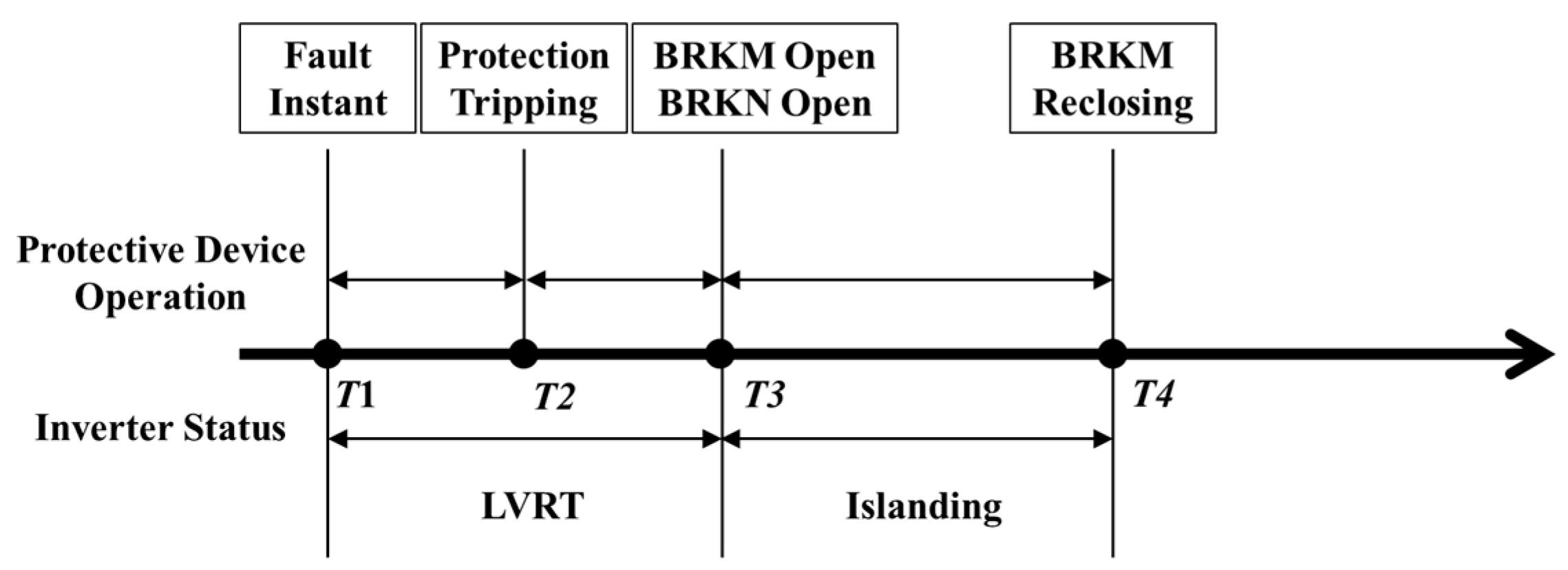
The dynamic behavior and operation sequence of PV inverters and line protection are illustrated in Figure 2 for the current dynamic sequence of protection operation. Currently, at time T1, a fault occurs at point K1 on the tie-line, and the PV inverters simultaneously enter LVRT mode. At time T2, the tie-line protection operates and sends a trip command to the respective circuit breakers. By time T3, circuit breakers BRKM and BRKN have opened, causing the PV power plant to enter an islanded state and exit LVRT mode.
As shown in Figure 2, after fault isolation, a mismatch exists between the PV generation and station load within the islanded system, leading to uncontrolled fluctuations in frequency and voltage. Shortly after time T3, the frequency or voltage protection of the PV inverters will operate, or if the islanding last for more than 2 s, the anti-islanding protection will operate, causing the PV inverters to be tripped off. By time T4, the grid-side circuit breaker BRKM initiates reclosing on dead-line. The PV plant side circuit breaker BRKN should be auto-reclosed on check-sync. As all PV inverters are tripped off, the circuit breaker BRKN cannot be reclosed on check-sync, all PV inverters are shut down and the PV plant has to go through a manual restoration process. This will take a long time to complete.
To overcome above problem, this paper proposes a fault ride-through control strategy based on the coordinated control of on-site energy storage units. Typically, the plant load of a PV power plant is about 1% of the PV generation capacity. In order to match the generation output and plant load in islanding operation mode, the control strategy proposed by the paper reduces the PV power output to zero once the operation of the tie-line protection is detected, and using the ESS to match the load, so to control the frequency and voltage of the islanded system in order to achieve rapid auto-reclose of tie-line and restore connection to the grid. The dynamic behavior and operation sequence of PV inverters and line protection are illustrated in Figure 3.
After a fault occurs on the tie-line, when the tie-line protection operation signal is detected at time T2 as shown in Figure 3, the control mode of the PV inverters will be switched from MPPT mode to PQ mode and its output power will be reduced to zero in order to match the plant load. At time T3 when circuit breakers BRKM and BRKN open, the PV plant will enter into islanding operation mode and ESS will supply the load. At time T3, the control mode of the ESS inverters will be switched from PQ mode to VF mode in order to support the voltage and frequency of the islanded PV plant. At time T4, the grid-side circuit breaker BRKM initiates reclosing on dead-line. The PV plant side circuit breaker BRKN is then auto-reclosed on check-sync. The PV plant is re-connected to grid within 2 s preventing anti-islanding protection operation.

2.3. Post-Fault Variation in Voltage and Frequency in the PV Plant

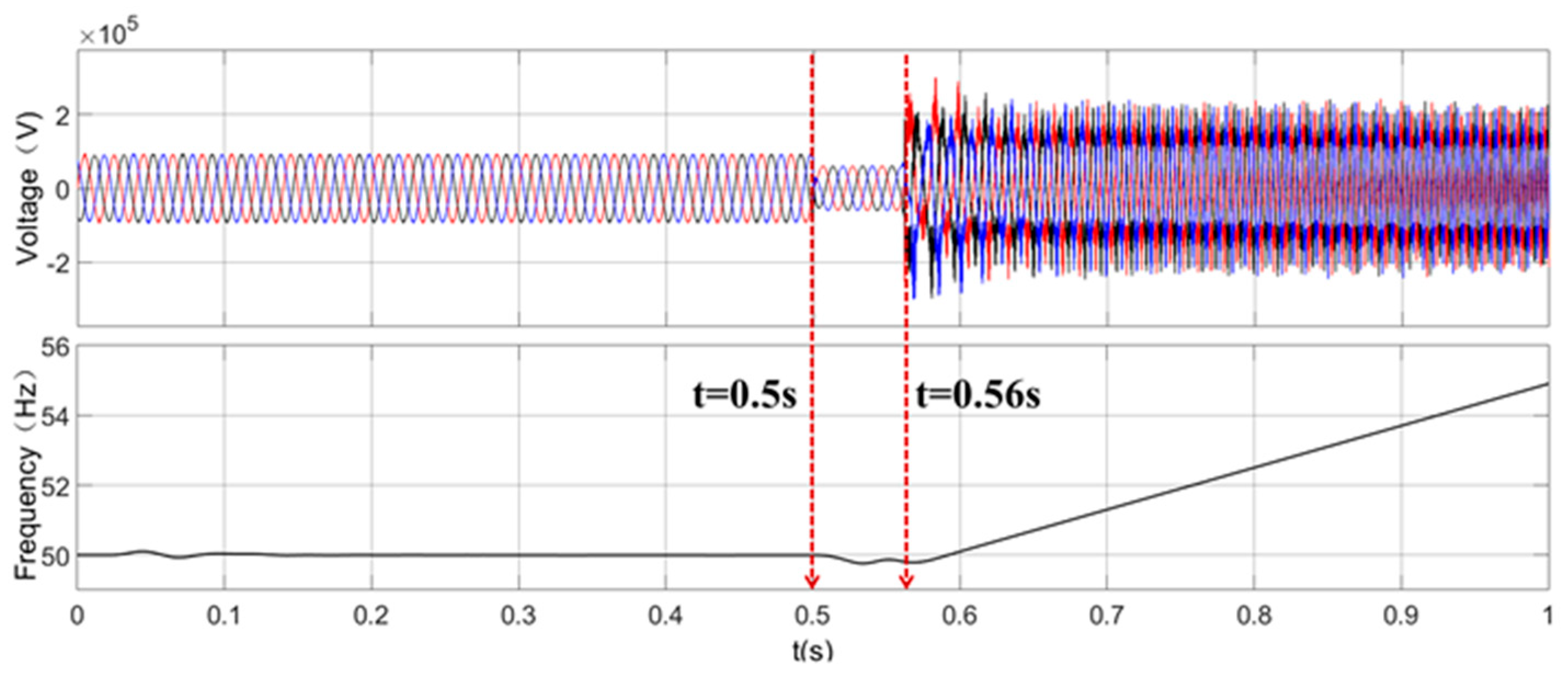
Figure 4 shows the waveforms of voltage and frequency variations at the point of common coupling (PCC, at breaker BRKN shown in Figure 1) following a three-phase short-circuit fault on the tie-line. The total PV power is 100 MW (operating in MPPT control mode), the total energy storage power is 10 MW (operating in PQ control mode), and the station load is 1 MW. The simulations are set as follows: at t = 0.5 s, a three-phase short-circuit fault occurs at the midpoint of the tie-line; at t = 0.52 s, the tie-line protection operates; at t = 0.56 s, the circuit breakers on both sides of the 110 kV tie-line open, clearing the fault and causing the PV power plant to enter an islanded state.
As observed in the figure, after the fault occurs, the voltage of the faulted phase at the PCC drops, and the frequency decreases with fluctuations. At t = 0.56 s, the plant enters an islanded state. Due to the imbalance between generation output and plant load, the voltage of the islanded system rises with severe distortion, and the system frequency gradually increases. By t = 0.7 s, the frequency exceeds 51 Hz and continues to rise, leading to system instability. The frequency protection then operates, disconnecting the inverters and resulting in a complete disconnection of the PV power plant from the grid.
From the above analysis, it can be concluded that the stochastic nature of PV power generation introduces challenges for setting protection reclosing schemes, with a high probability of causing PV disconnection or reclosing failure. Furthermore, when a tie-line fault leads to the disconnection of PV inverters, the manual process of restoration of the entire plant takes a long time. This process results in significant power waste and adversely affects the security and stability of grid operation.

3. Fault Ride-Through (FRT) Strategy Based on Coordinated Regulation of Energy Storage Systems

3.1. Classic Control Modes of Inverters

(1)
MPPT control mode
Maximum Power Point Tracking (MPPT) control is an optimization strategy widely used in photovoltaic power generation. Its core objective is to track and maintain the maximum power output of renewable energy generation units in real-time under varying external environmental conditions. As the P-V characteristic curve of photovoltaic arrays exhibits nonlinearity with a single extremum point, the MPPT controller periodically samples the output voltage and current to calculate the instantaneous power. Based on specific algorithms, it generates control signals that drive the power electronic converter to adjust its duty cycle or phase shift, thereby dynamically altering the operating point of the generation unit to stabilize it at or infinitely close to the maximum power point.
P P V = V P V   ×   I P V
d P P V d V P V = 0
Equation (1) describes the output characteristics of the photovoltaic system, where P P V represents the output power of the PV array, V P V denotes the terminal voltage of the array, and I P V is its output current. Equation (2) defines the condition satisfied at the Maximum Power Point (MPP), which can be derived using the Incremental Conductance method to establish the corresponding MPP criterion. The overall control process is as follows: the MPPT algorithm module calculates the voltage reference value V r e f that drives the system toward the MPP based on the sampled V P V and I P V . This reference value is then fed into a voltage-loop PI controller, whose output serves as the reference for the current inner loop. Finally, high-frequency PWM drives the switching devices, enabling precise and rapid adjustment of the operating point.
(2)
PQ control mode
PQ control mode is a grid-connected control strategy in which the grid-tied inverter operates as a controlled current source. The primary objective is to accurately inject specified active power (P) and reactive power (Q) into the grid. This control mode relies on a stable grid with sufficient capacity, where voltage amplitude and frequency are considered constant. The controller utilizes a high-precision phase-locked loop (PLL) to achieve real-time and accurate synchronization with the grid voltage vector. This enables the decoupling of active and reactive current components, allowing for independent control and precise power output. The control structure typically employs a classic dual-loop configuration.
In the outer power loop, the reference active and reactive power values ( P r e f and Q r e f ) are compared with the measured actual power (P, Q). The resulting error signals are processed by PI controllers, which generate the d-axis and q-axis current references ( I d r e f and I q r e f ) for the inner current loop.
The inner current loop receives these current commands ( I d r e f ,   I q r e f ) and compares them with the measured actual currents ( I d , I q ). The current errors are rapidly tracked through high-bandwidth PI controllers (or PR controllers), producing the voltage commands ( V d r e f , V q r e f ). These voltage commands then undergo inverse Park transformation and SVPWM to drive the inverter bridge, ultimately generating the desired output current waveform.
(3)
VF control mode
VF control mode is an operational strategy suitable for islanded systems or applications where the inverter serves as the primary power source. In this mode, the inverter is controlled as an ideal voltage source, with its core objective being to establish and maintain a sinusoidal AC voltage with constant amplitude and frequency for the local load. This controller does not directly regulate output power but adjusts its output voltage in response to load variations. The fundamental VF control typically employs a dual-loop control structure based on a rotating reference frame, incorporating both voltage and current feedback loops. This architecture ensures precise regulation of the output voltage and delivers excellent dynamic response characteristics.
The voltage outer loop is responsible for regulating the magnitude of the output voltage. The voltage control equation is as follows:
I d , ref = K p , v + K i , v s ( V d , ref V d , fb )
I q , ref = K p , v + K i , v s ( V q , ref V q , fb )
Here, V d , ref = V ref (the rated voltage magnitude), and V d , fb represents the d-axis feedback component of the output voltage. K p , v and K i , v are the proportional and integral gains of the voltage loop PI controller, respectively. Additionally, V q , ref = 0 V, with the objective of eliminating the q-axis component of the output voltage. This ensures perfect synchronization of the output voltage with the d-axis reference, thereby avoiding phase misalignment. The outputs of the voltage outer-loop PI controller, I d , ref and I q , ref , serve as the reference commands for the current inner loop, essentially representing the current components required to maintain the specified voltage.
V d , pwm = K p , i + K i , i s ( I d , ref I d , fb )
V q , pwm = K p , i + K i , i s ( I q , ref I q , fb )
The current inner loop serves as the system’s innermost control layer, responsible for rapidly and accurately tracking the current references generated by the voltage outer loop, as well as providing fast dynamic response to load disturbances. Here, K p , i and K i , i denote the proportional and integral gains of the current-loop PI controller, respectively, while I d , fb represents the d-axis feedback component of the output current. The outputs of the current loop, V d , pwm and V q , pwm , undergo an inverse Park transformation to generate three-phase voltage modulation signals in the stationary reference frame. These signals are then processed via Space Vector Pulse Width Modulation (SVPWM) to generate the PWM signals that drive the inverter bridge.
When the energy storage controller receives the islanding switch command, and the energy storage system switches from grid-connected power control mode (P-Q) to islanding mode (V-F). The actual AC voltage is compared with the reference V ref , and the result serves as the input for the active power loop in the d-q inverse transformation. The phase angle of the AC modulation voltage for the energy storage converter is determined by a Voltage Controlled Oscillator (VCO), which directly controls the islanding frequency. The reactive power loop voltage reference for the energy storage system is set to 0. V d , pwm and V q , pwm undergo d-q inverse transformation and are compared with a triangular carrier wave to generate PWM signals that drive the energy storage inverter.
Upon entering islanded mode, to ensure stable islanded operation, the PV inverters can be switched from Maximum Power Point Tracking (MPPT) mode to PQ control mode with their output power set to zero, thereby reducing the total system power output. Simultaneously, to support the island’s voltage and frequency, the energy storage inverters can be switched from PQ control mode to V-F control mode, providing stable voltage and frequency support for the islanded grid operating in off-grid mode. In this state, the PV inverters do not export power, while the energy storage inverters adjust their output according to the station load to maintain voltage and frequency stability. The power flow within the islanded system is directed from the energy storage system to the station load.

3.2. MPPT and PQ Control Modes for Inverters in PV Power Plants

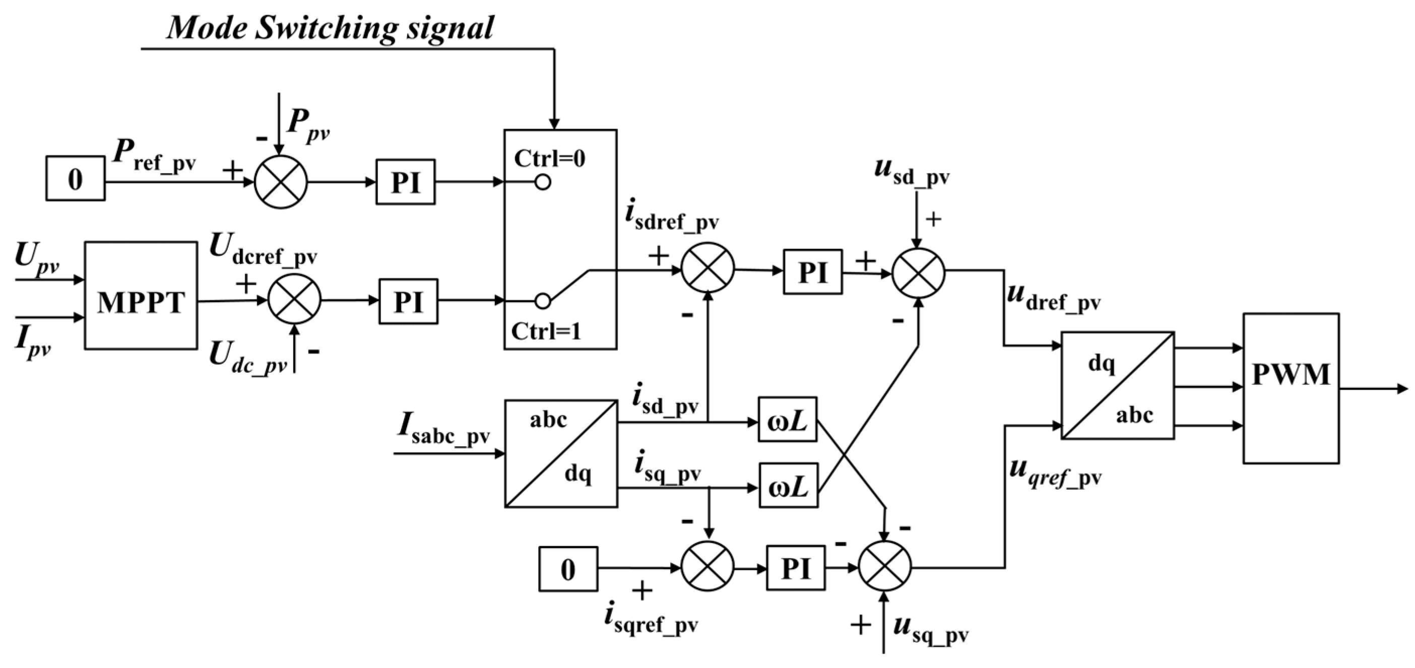
A photovoltaic (PV) power generation system primarily consists of a PV array, DC-DC circuit, inverter, filter, and controller. Its topological structure and control block diagram are shown in Figure 5. Under normal operating conditions, the front-stage maximum power point tracking controller regulates the PV array to operate at its maximum power point. This is achieved by controlling the duty cycle of the switching devices in the DC-DC circuit to implement Maximum Power Point Tracking (MPPT) control. The DC-side voltage of the rear-stage DC-AC inverter is maintained stable by the voltage outer loop of the controller, while the current inner loop controls the AC-side input current to track the sinusoidal input voltage.
When Ctrl = 1, the PV system operates in MPPT control mode, tracking the maximum power point of the PV array to inject power into the grid. Here, Upv and Ipv represent the DC voltage and DC current of the PV array, respectively. These values are processed through an MPPT algorithm to calculate the DC reference voltage Udcref_pv corresponding to the maximum power point of the PV array. This reference voltage is compared with the actual DC-side voltage Udc_pv of the PV inverter, and the error is passed through a PI controller before being sent to the control mode selector.
When Ctrl = 0, the PV system operates in PQ control mode. In this mode, the reference power Pref_pv is compared with the actual output power Ppv of the PV system. The resulting error is processed by a PI controller and also fed into the control mode selector. Based on the control mode switching signal, the selector switches between control modes and outputs the corresponding active current reference command idref_pv for the inner loop. This command is then processed by the inner-loop controller to generate the active-loop reference voltage Udref_pv. Similarly, the reactive current reference command iqref_pv is processed by the inner-loop controller to produce the reactive-loop reference voltage Uqref_pv. The active and reactive reference voltages undergo inverse Park transformation and are compared with a triangular carrier wave to generate Pulse Width Modulation (PWM) signals, which drive the PV inverter.

3.3. PQ and VF Control Modes for Energy Storage Inverters

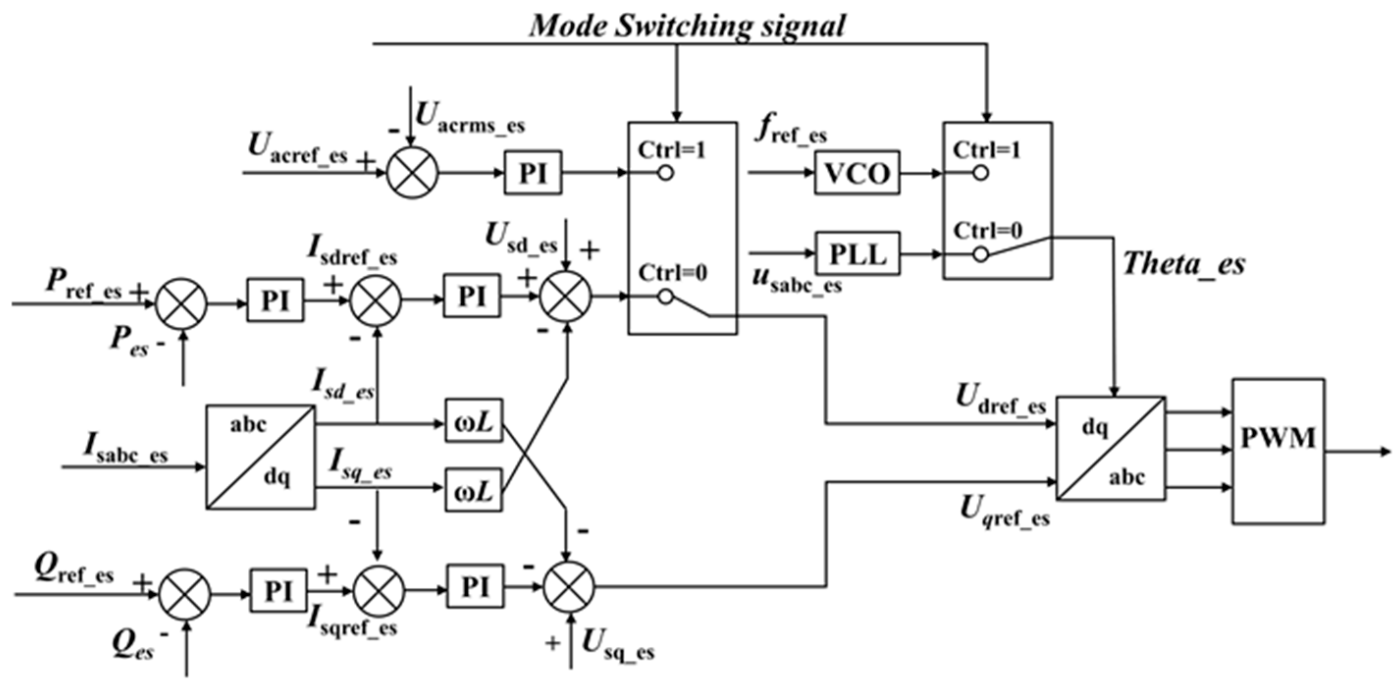
The control mode of the energy storage inverter is shown in Figure 6:
When Ctrl = 0, the energy storage inverter operates in the conventional PQ control mode. The active power reference value Pref_es and reactive power reference value Qref_es are typically provided by the Energy Management System (EMS) based on the requirements for suppressing power fluctuations in the PV power plant. After Pref_es is compared with Pes, it is processed through a PI controller and fed into the inner-loop controller to obtain Udref_es. Similarly, Qref_es is compared with Qes, processed through a PI controller and the inner-loop controller, to obtain Uqref_es.
When the energy storage controller receives an islanding detected signal, the Ctrl signal changes from 0 to 1, and the energy storage system switches from the grid-connected power control mode (PQ) to the VF control mode for controlling the voltage and frequency of the islanded system. The actual AC voltage Uac_es is compared with the given reference Uacref_es, and the result is used as the input for the active loop after inverse dq transformation. The phase angle of the AC modulated voltage of the energy storage converter is determined by a Voltage Controlled Oscillator (VOC), which directly controls the islanded frequency. The reference value for the reactive loop voltage Uqref_es is set to 0. Udref_es and Uqref_es undergo inverse dq transformation and are compared with a triangular carrier wave to generate PWM signals, which drive the energy storage inverter. Through the above control strategy, the energy storage inverter can respond to islanding switching commands and switch between grid-connected fixed power output mode and islanded frequency/voltage control mode.

3.4. Stability Control and Re-Synchronization Strategy for Islanded PV Plant

Based on this, this paper proposes a transient tie-line fault ride-through (FRT) strategy for PV power plants. Through coordinated control of PV and energy storage inverters, stable operation is achieved for islanded PV plant after a fault. Subsequently, by coordinating with line reclosing device, island re-synchronization is achieved. The specific control strategy is illustrated in Figure 7:
The Specific Control Strategy is as follows:
(1) Normal Grid-Connected Operation:
PV inverters operate in Maximum Power Point Tracking (MPPT) mode. The energy storage system operates in P/Q mode, absorbing or supplying power according to setpoints. The Automatic Generation Control (AGC) and Automatic Voltage Control (AVC) systems regulate total power output and voltage stability.
(2) Post-Fault PV Inverter Control Mode Switching:
Upon detection of a fault on the 110 kV tie-line (via protection signals within 20–30 ms after fault occurrence), PV inverters switch from MPPT to P/Q mode, with active and reactive power outputs (P and Q) set to zero. PV inverters exit Low Voltage Ride-Through (LVRT) mode.
(3) Control Mode Switch of Energy Storage Inverters in Islanded Operation:
When the 110 kV tie-line circuit breaker opens and zero current is detected, the PV plant is confirmed to be in islanded operation. The energy storage inverters immediately switch from P/Q control mode to V/F mode, exiting LVRT mode to provide voltage and frequency support for the islanded grid.
(4) Islanded Stability Control and Synchronization Check:
After the 110 kV tie-line protection operates, reclosing is initiated. The grid side circuit breaker is closed first on dead-line, the plant side CB employs a synchronism-check scheme to continuously monitor whether the island’s voltage, frequency, and phase meet grid-synchronization criteria. If conditions are satisfied, a reclosing command is issued immediately.
(5) Reconnection and Inverter Control Mode Restoration:
For transient faults, reclosing is successful. Upon detecting the circuit breaker’s status is changed from open to closed position and the tie-line voltage is greater than 70% of its rated voltage, Energy storage inverters are then switched from V/F mode back to P/Q mode, with P and Q setpoints restored to pre-fault values. PV inverters switch from P/Q mode back to MPPT mode, with plant-level AGC/AVC systems resuming control.

3.5. On-Site Engineering Scheme

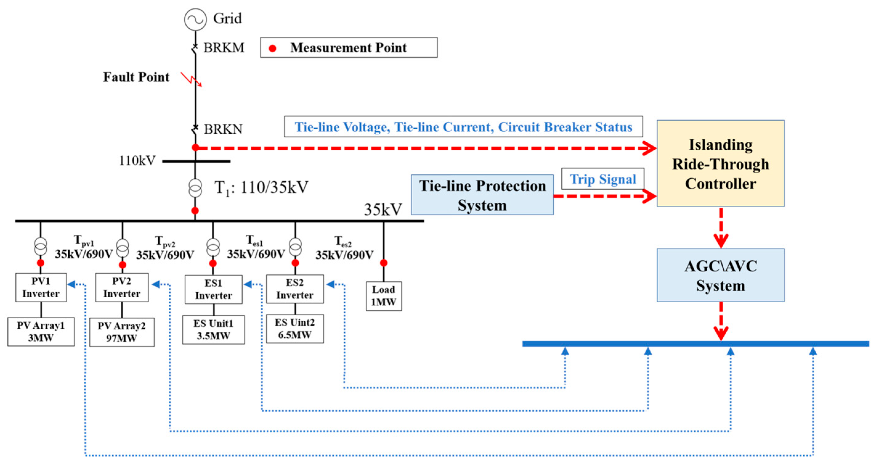
As shown in Figure 8, the specific engineering scheme of the proposed control strategy for the PV power plant is presented. Currently, PV power plants primarily rely on AGC and AVC systems to regulate power output and maintain voltage stability according to dispatch instructions. Due to technical confidentiality and copyright restrictions of the equipment, the AGC program cannot be directly modified, but relevant communication interfaces are accessible. Therefore, a standalone islanding ride-through controller can be developed independently. This controller needs to collect signals such as tie-line voltage, current, circuit breaker status, and protection operation signals from protection devices. The proposed control strategy is integrated into this controller, whose output signals include mode switching commands and power setpoints for each inverter. These signals are then fed into the AGC/AVC system via communication interfaces, and control commands are distributed to individual inverters through the fiber-optic network, thereby achieving effective control of all inverters in the entire plant.
While the PV power station is under normal operation, it relies on the AGC/AVC system to receive commands from the upper-level dispatch department, thereby controlling the station’s power output. Following a tie-line fault, the AGC/AVC system switches to local control mode. The islanding ride-through controller then generates appropriate control commands. These commands are delivered to the PV and energy storage inverters via the AGC system and the communication network to execute necessary control mode transitions. Ultimately, through the coordinated efforts of PV and energy storage systems, pre-defined strategies are implemented to stabilize the island and achieve re-synchronization, ensuring successful fault ride-through.

4. Simulation Verification

4.1. Simulation Model Construction

With reference to an actual PV power plant in China, a simplified simulation model was developed in MATLAB R2022B, as shown in Figure 8. The PV plant has a total capacity of 100 MW, each PV converter has a rating of 3 MW. The model shown in Figure 9 consists of PV Array 1 of 3 MW simulating a PV convertor, and PV Array 2 of 97 MW simulating remaining PV converters. Each array is connected to the 35 kV bus through PV inverters and 690 V/35 kV step-up transformers. The energy storage system has a total capacity of 10 MW, each converter has a rating of about 3.5 MW. The model consists of Energy Storage Unit 1 (3.5 MW) simulating a single convertor, and Energy Storage Unit 2 (6.5 MW) simulating remaining ESS converters. Each unit is connected to the 35 kV bus through energy storage inverters and 690 V/35 kV step-up transformers. The station load is 1 MW. The PV plant is connected to the grid via a 35 kV/110 kV step-up transformer and a single-circuit 110 kV tie-line.

4.2. Simulation Results Analysis

The simulation conditions are set as follows: PV system (MPPT mode, output power 100 MW); energy storage system (PQ mode, output power 10 MW); load 1 MW. A three-phase short-circuit fault (phase-to-phase fault resistance 2 Ω) is applied at the midpoint of the tie-line. The islanding frequency is set to 50.5 Hz in order to generate a slip frequency for auto-reclosing. The protection operating time is set to 20 ms, and the circuit breaker operating time is 40 ms. The fault occurs at t = 0.5 s. The tie-line protection operates at t = 0.52 s. The circuit breakers on both sides of the tie-line open at t = 0.56 s, clearing the fault. The grid-side breaker of the tie-line recloses at t = 1 s. The simulation results are as follows:
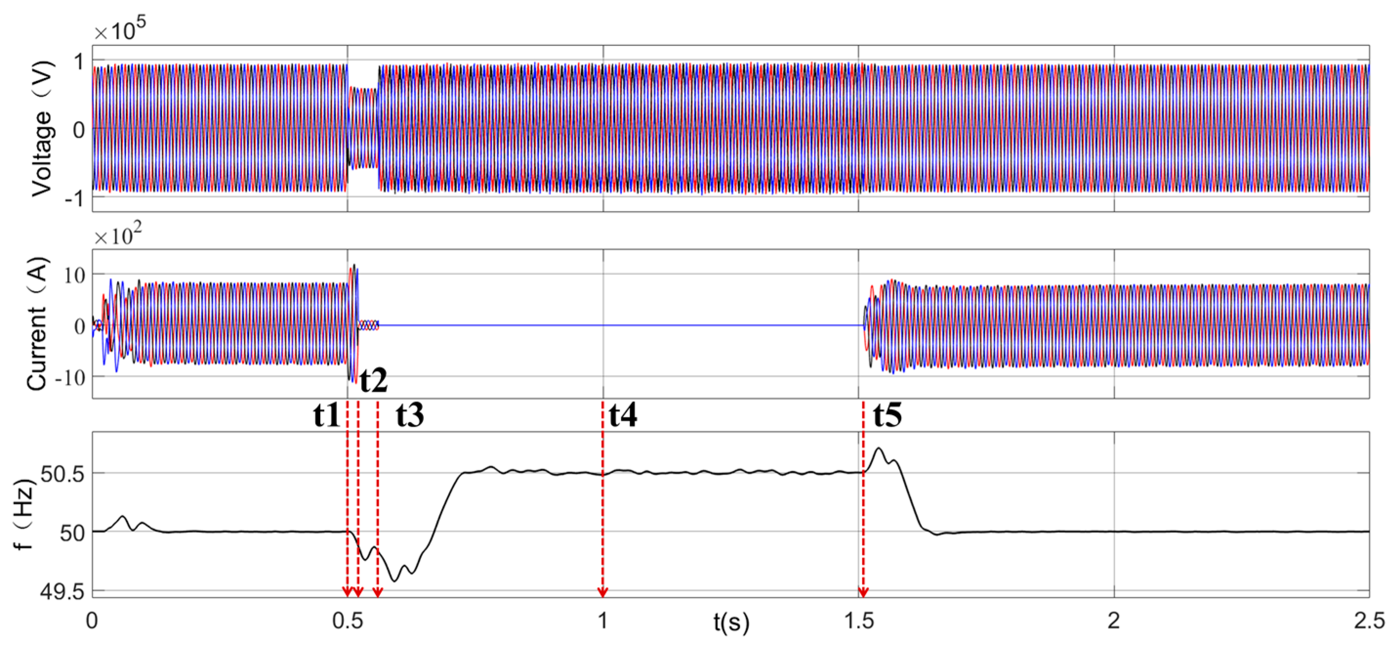
Figure 10 shows the voltage and frequency variations at the 110 kV point of common coupling (PCC) of the PV power plant side before and after the fault. At t = 0.5 s, a three-phase short-circuit fault occurs on the tie-line, resulting in a decrease in the fault-phase voltage and an increase in the fault current (corresponding to time t1). At t = 0.52 s, the protection operates. The PV system switches from MPPT mode to PQ control mode with both active and reactive power (P and Q) set to zero. The system current is now supplied by the energy storage system. Correspondingly, the tie-line current decreases (corresponding to time t2). At t = 0.56 s, the circuit breakers on both sides of the 110 kV tie-line open, clearing the fault and causing the PV plant to enter an islanded state. The tie-line current drops to zero (corresponding to time t3). At this point, the energy storage inverters switch from PQ mode to VF mode to provide frequency and voltage support for the islanded system. After the control mode switch of the energy storage inverters, the frequency of the islanded system gradually increases and stabilizes at the setpoint of 50.5 Hz by t = 0.725 s. At t = 1 s, the grid-side circuit breaker of the tie-line recloses (corresponding to time t4). Subsequently, the system enters the synchronism-check reclosing stage. At t = 1.511 s (corresponding to time t5), the plant-side circuit breaker of the tie-line successfully recloses. Following this, the energy storage inverters switch from VF control mode back to PQ control mode, and the PV system switches from PQ mode back to MPPT mode. The voltage at the PCC returns to a stable value, the current gradually recovers to normal operating conditions, and the system frequency restores to 50 Hz, completing the entire fault ride-through process. In terms of timing, the fault occurs at t = 0.5 s and the reclosing is completed at t = 1.511 s, resulting in a total process duration of 1.011 s. This is less than the 2 s operating time of the anti-islanding protection, leaving nearly 1 s of safety margin when considering additional delays.
Figure 11 shows the variation curves of voltage, current, and total power on the 35-kV side of the PV power plant (i.e., the LV side of the 35/110kV transformer). The overall trends of voltage and current are generally aligned with those observed at the 110-kV point of common coupling (PCC). The change in total power clearly reflects the operational states and control mode transitions of both the PV and energy storage systems during different stages.
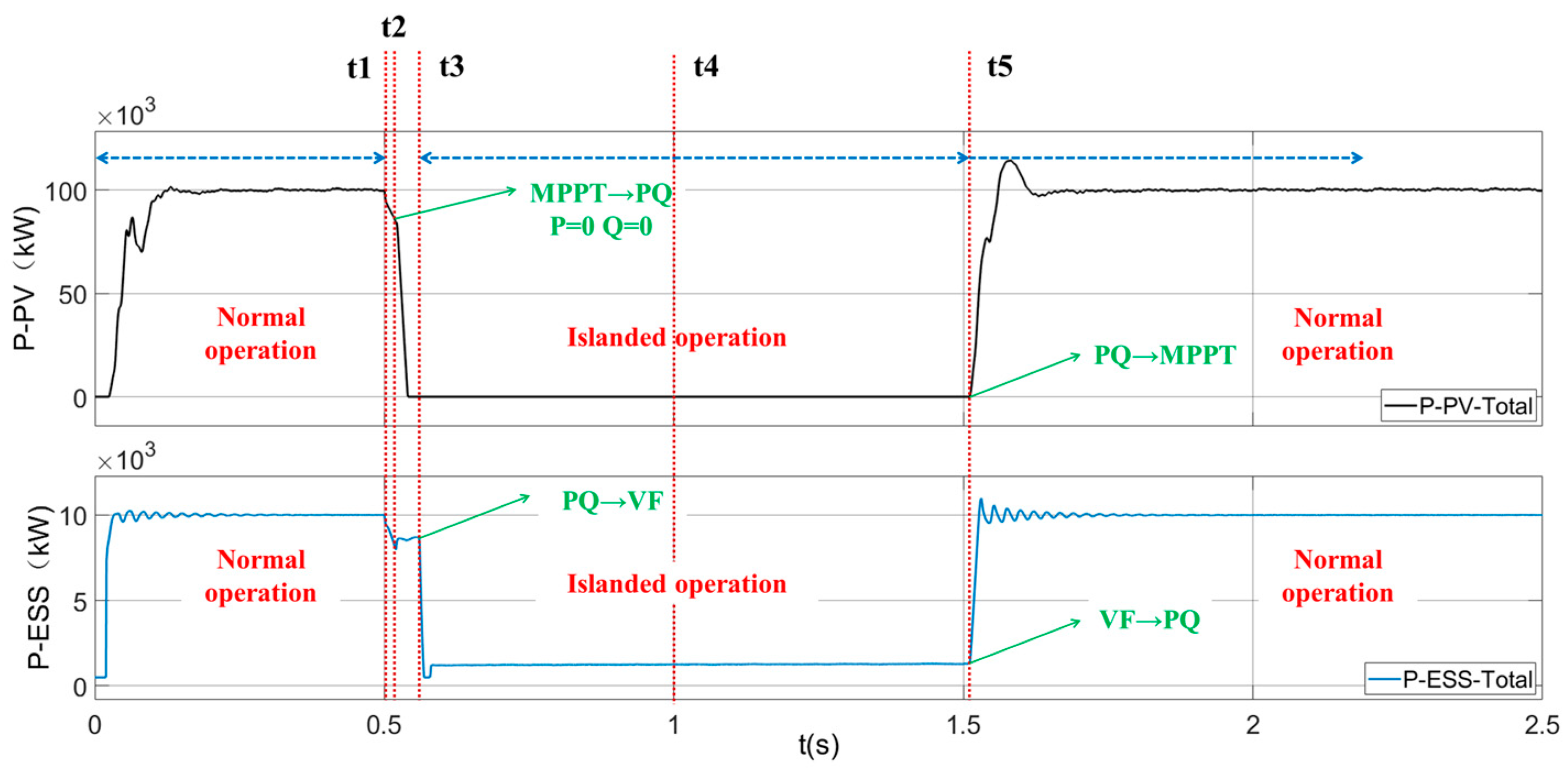
As shown in Figure 11: When a fault occurs at t = 0.5 s (corresponding to time t1), the total active power delivered to the grid by the plant before the fault is 110 MW, comprising 100 MW from PV and 10 MW from energy storage. After the fault occurs, the output power of the plant decreases slightly. At t = 0.52 s, the protection operates. Since the PV system switches to PQ mode with both P and Q set to zero, the total system power begins to decline gradually (corresponding to time t2), eventually stabilizing at 10 MW, which is supplied solely by the energy storage system. At t = 0.56 s, the circuit breakers on both sides of the tie-line open, reducing the tie-line current to zero (corresponding to time t3).
Given that the station load is only 1 MW, Energy Storage Unit 1 (3.5 MW) switches from PQ control mode to VF control mode to match the station load and stabilize voltage and frequency, while Energy Storage Unit 2 (6.5 MW) reduces its power output to zero. At t = 1 s, the grid-side circuit breaker of the tie-line recloses (corresponding to time t4). At t = 1.511 s, reclosing the plant side circuit breaker is successful. Energy Storage Unit 1 switches back from VF mode to PQ mode, Energy Storage Unit 2 resumes its initial power setpoint, and the PV inverters return to MPPT control mode. The system power gradually increases and stabilizes at 110 MW, completing the entire fault ride-through process.
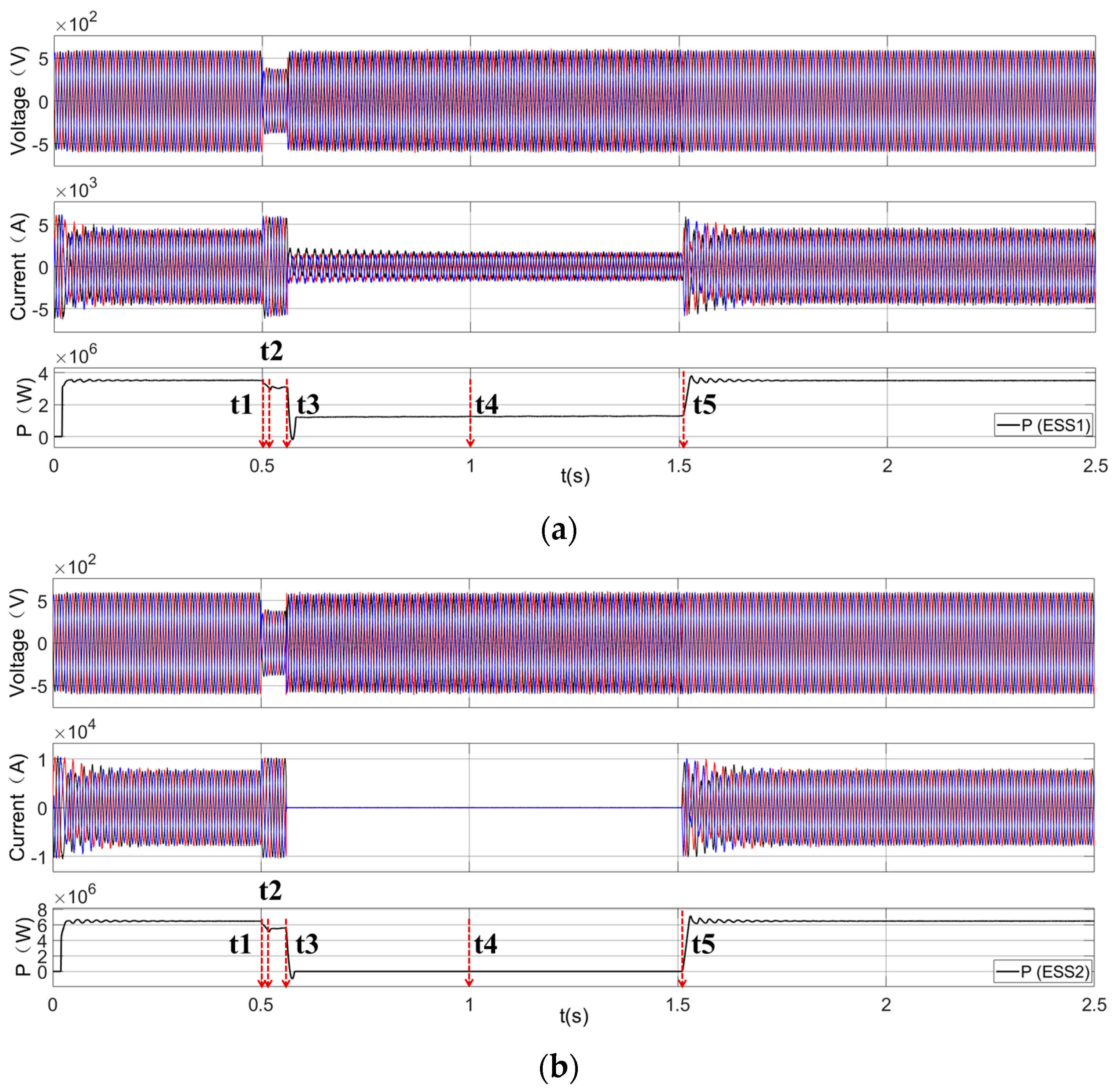
During the fault ride-through process, the variations in voltage, current, and power of the energy storage inverters are shown in Figure 12. It can be observed that the control modes of both energy storage unit inverters switch according to the predefined logic. Specifically, Energy Storage Unit 1 rapidly switches to VF control mode after the plant enters the islanded state, matching the load to maintain voltage and frequency stability in the islanded grid. Meanwhile, Energy Storage Unit 2 quickly reduces its output power to support source–load balance.
After the islanded system operates stably, it awaits the reclosing of the grid-side circuit breaker of the tie-line first. Subsequently, the plant-side circuit breaker performs synchronism-check reclosing. The inverter modes switch according to the predefined logic, and the plant resumes grid-connected operation. The entire process is completed within 2 s, preventing the activation of anti-islanding protection.
As shown in Figure 13, the mode switching timings and power variation curves of PV inverters and energy storage inverters during the fault ride-through process are presented. It can be observed that according to the proposed control strategy, when a tie-line fault occurs and the PV plant enters an islanded state, the support from energy storage units enables source–load balance in the islanded system. This achieves stable control of the islanded voltage and frequency. Furthermore, through coordination with reclosing devices, island re-synchronization can be accomplished within 2 s after the fault, thereby preventing the disconnection of the PV plant, ensuring secure and stable system operation, and enhancing the power supply reliability of the plant.
This study thoroughly considers various scenarios such as the initial state of the plant, the type of tie-line fault, the communication time delay between various devices, and different circuit breaker operating time. also islanded system operation frequency. Simulations were conducted under 10 different scenarios to validate the proposed control strategy. The specific simulation conditions and results are summarized in Table 1:
It can be seen from the simulation results, under all 10 scenarios defined in this study, the proposed control strategy effectively achieves stable control and re-synchronization of the PV plant’s islanded system within 2 s after fault occurrence, regardless of the tie-line fault type. Control delays and communication delays within certain limits do not affect the stable execution of the control strategy or islanded stability. The time required for re-synchronization is primarily related to the set stable operating frequency of the islanded system. When the islanded frequency is set to 49.5 Hz, the re-synchronization time is generally around 1.675 s after the fault. When the islanded frequency is set to 50.5 Hz, the re-synchronization time is typically about 1.011 s after the fault. This is primarily because the islanded frequency directly affects the speed of the synchronism-check process with the grid-side voltage, thereby influencing the reclosing time of the plant-side circuit breaker on the tie-line.

4.3. Recommended Parameter Settings

Based on the simulation results and practical field conditions, the following recommendations are proposed.
First, to achieve voltage and power support from the energy storage system, both its capacity and state of charge must meet the required specifications. According to our simulation results and anti-islanding protection requirements, the entire fault ride-through process must be completed within 2 s, which has been verified as achievable through simulations. This necessitates that the energy storage system provides full power support throughout the entire islanding operation after the PV plant enters islanded mode. Therefore, the output power of the energy storage must exceed the station load power, and its remaining energy must be sufficient to sustain at least 2 s of operation. While this represents an extreme scenario, a larger safety margin is considered for practical field applications. Hence, we recommend configuring the energy storage system to support at least 60 s of operation.
Second, the recommendation of the maximum communication delay parameters is primarily based on field measurements from the station control system and the simulation results obtained in this study. Field measurements indicate that the communication delay of the station control system is less than 10 ms. To analyze the impact of communication delay on the proposed control strategy, this study simulated the system’s dynamic response following a tie-line fault under total communication delays (T_C-PV + T_C-ESS) of 20 ms and 40 ms, respectively. The results, summarized in Table 1, demonstrate that the system can maintain stable islanding operation and achieve successful reconnection even with a delay of up to 40 ms. Therefore, based on the field measurements and simulation results, considering these findings and incorporating a reasonable safety margin, the recommended communication delay in this study is set not to exceed 30 ms.
Third, according to the actual protection setting schemes for photovoltaic systems, the anti-islanding protection actuation time is generally set at 2 s. This is the key reason why the entire control strategy in this study must be strictly completed within 2 s. The simulation results demonstrate that the proposed control strategy can achieve stable islanding control and re-synchronization within this timeframe. Considering a certain safety margin, it is recommended that the anti-islanding protection time setting for the power station should be greater than or equal to 2 s. To ensure the success rate of islanding ride-through, the synchro check reclosing should not include any intentional time delay—meaning the closing command should be issued immediately upon detecting synchronization. Furthermore, taking into account the actual performance parameters of inverters and the frequency requirements specified in GB/T 19964-2012 [23] “Technical Requirements for Connecting Photovoltaic Power Station to Power System”, which allows inverters to operate continuously at 49.5 Hz, it is recommended to set the stable frequency of the islanded system at 49.5 Hz.
In summary, the following parameters are recommended for the practical implementation of the control strategy proposed in this study at PV power plants:
(1)
To maintain stable islanded operation of the PV power plant, at least one energy storage unit must satisfy: Output power PESS > PLoad (where PLoad is the maximum station auxiliary load); Remaining energy capacity> PLoad × 60s.
(2)
Communication delays between devices should be limited to < 30 ms;
(3)
Plant anti-islanding protection operating time setting ≥ 2 s; Synchronism-check reclosing (no delay); Islanded stable frequency setpoint: 49.5 Hz.

5. Conclusions

To address long time disconnection of photovoltaic (PV) power plants caused by tie-line faults, this paper proposes a tie-line fault islanding ride-through control strategy based on coordinated energy storage regulation. This strategy can maintain stable islanded operation post tie-line a fault and achieve re-synchronization of the PV plant through coordination with reclosing devices. Simulation results have shown that for transient tie-line faults, the proposed control strategy effectively supports voltage and frequency stability of the islanded system and enables re-synchronization of the PV plant within 2 s after fault occurrence. This successfully prevents anti-islanding protection operation of PV plant, maintaining inverter connectivity and thereby ensuring full plant ride-through without permanent disconnection. Finally, based on typical existing PV plant configurations, a specific retrofit implementation scheme is provided, offering a feasible solution for site application of the fault ride-through strategy. Subsequently, we will proceed with hardware-in-the-loop real-time simulation verification and field deployment for practical testing and validation.

Author Contributions

Conceptualization, Z.H. and B.P.; methodology, A.W.; validation, D.W. and X.B.; formal analysis, J.Y. and F.X.; data curation, B.P.; writing—original draft preparation, P.S.; writing—review and editing, A.W. All authors have read and agreed to the published version of the manuscript.

Funding

This research was funded by “Science and Technology Project Funding from the Collective Enterprise of State Grid Zhejiang Electric Power Co., Ltd.”, grant number: No. HZTLKJ2023-01.

Data Availability Statement

The original contributions presented in this study are included in the article material. Further inquiries can be directed to the corresponding author.

Conflicts of Interest

Authors Bo Pan, Xiangyi Bi, Dong Wan, Jinsong Yang are employed by the company Anji Power Supply Company of State Grid Zhejiang Electric Power Co., Ltd. Author Feng Xu is employed by the company Zhejiang Anji General Electric Power Development Co., Ltd. Author Zhihua Huang is employed by the company State Grid Huzhou Electric Power Supply Company. The remaining authors declare that the research was conducted in the absence of any commercial or financial relationships that could be construed as a potential conflict of interest.

References

  1. International Energy Agency (IEA). World Energy Outlook 2023 [R/OL]. (2023–10–01) [2024–04–21]. Available online: https://www.eia.gov/outlooks/ieo/index.php (accessed on 24 October 2023).
  2. International Renewable Energy Agency (IRENA). Renewable Capacity Statistics 2024 [R/OL]. (2024–03–01) [2024–04–21]. Available online: https://www.irena.org/Publications/2024/Mar/Renewable-capacity-statistics-2024 (accessed on 27 March 2024).
  3. He, J.; Ma, S.; Zhang, X.; Luo, M.; Li, L.; Niu, J.; Liu, H.; Jin, P.; Liang, Y. Transient equivalent modelling of a wind farm based on QPSO-Based wind turbine fault ride-through control. Energies 2025, 18, 1205. [Google Scholar] [CrossRef]
  4. Avilan-Losee, G.; Gao, H. Grid-Forming buck-type current-source inverter using hybrid model-predictive control. Energies 2025, 18, 4124. [Google Scholar] [CrossRef]
  5. Ojo, K.E.; Saha, A.K.; Srivastava, V.M. Review of advances in renewable energy-based microgrid systems: Control Strategies, Emerging Trends, and Future Possibilities. Energies 2025, 18, 3704. [Google Scholar] [CrossRef]
  6. Xu, S.; Wang, Y.; Sun, H.; Bi, J.; Lan, T. Insights from renewable energy outage accidents abroad for secure and stable operation of power grids in China. Autom. Electr. Power Syst. 2024, 48, 1–8. [Google Scholar]
  7. Zhao, H.; Wang, T.; Hu, P.; Han, J.; Liu, Y. Control strategy for stable operation of islanded microgrid with dual-drive of improved VSG and improved droop control. Proc. CSU-EPSA 2024, 36, 117–126. [Google Scholar] [CrossRef]
  8. Wang, Z. Research on Key Technologies for Frequency Stability Control of Virtual Synchronous Generator Parallel System in Island Microgrid. Ph.D. Thesis, Hunan University, Changsha, China, 2023. [Google Scholar]
  9. Sun, J.; Wang, X.; Huang, J.; Cao, H.; Mei, N.; Li, Z. MPC-VSG Based Control Strategy for Dynamic Stability of Frequency and Voltage in Islanded Microgrid. Electr. Power 2023, 56, 51–60. [Google Scholar]
  10. Xie, D.; Xiao, S. Research on static voltage stability during fault low voltage ride-through in renewable energy integrated power grids. Proc. CSEE 2024, 45, 6777–6790. [Google Scholar] [CrossRef]
  11. Xu, W.; Liu, S.; Wu, J.; Dong, Z. Research on fault-ride through strategy of Desert-Gobi-Wasteland new energy base connected with grid-forming energy storage. Inn. Mong. Electr. Power 2024, 42, 3–13. [Google Scholar] [CrossRef]
  12. Zhai, W.; Tian, X.; Kang, P.; Chen, S.; Kong, J.; Jia, K. Adaptive reclosing method based on PV fault transient outage control and capacity calculation. Electr. Power Autom. Equip. 2025, 45, 96–102. [Google Scholar]
  13. Dai, Z.; Luan, K.; Wu, T.; Zhou, J.; Shang, C. Multi-photovoltaic two-stage fault ride-through coordination control strategy. Proc. CSEE 2025, accepted, 1–13. [Google Scholar]
  14. Zheng, T.; Ma, Y.; You, Y.; Hu, S. A fast standby automatic switching scheme for photovoltaic power station considering energy storage cooperative Control. Trans. China Electrotech. Soc. 2025, accepted, 1–14. [Google Scholar] [CrossRef]
  15. Wei, C. Multi-Scenario Fault Fast Self-Healing Control Technology and Application for New Distribution Network Based on Energy Storage. Ph.D. Thesis, Hunan University, Changsha, China, 2023. [Google Scholar]
  16. Xie, X.; He, J.; Mao, H.; Li, H. New issues and classification of power system stability with high shares of renewables and power electronics. Proc. CSEE 2021, 41, 461–475. [Google Scholar] [CrossRef]
  17. Wang, G.; Huang, Y.; Wang, C.; Shahidephour, M.; Hao, Q. Voltage-adaptive strategy for transient stability enhancement of power systems with 100% renewable energy. IEEE Trans. Autom. Sci. Eng. 2025, 22, 1364–1376. [Google Scholar] [CrossRef]
  18. Alhasnawi, B.N.; Jasim, B.H.; Anvari-Moghaddam, A.; Blaabjerg, F. A new robust control strategy for parallel operated inverters in green energy applications. Energies 2020, 13, 3480. [Google Scholar] [CrossRef]
  19. Huang, R.; Wu, Z.; Xu, X.; Quan, X.; Li, M.; Liu, M. A Multi-Resonant based reference feedforward adaptive voltage control for Grid-Forming inverter in island mode to compensate system uncertain and harmonic distortions. Int. J. Electr. Power Energy Syst. 2025, 164, 110438. [Google Scholar] [CrossRef]
  20. Mothi, B.R.; Srinivas, L.R. Optimal power controller-based voltage and frequency control of DG unit in an island mode microgrid using hybrid differential evolution. J. Electr. Eng. 2021, 1, 88–97. [Google Scholar]
  21. Wen, W.; Niu, B.; Xu, A.; Guo, X.; Shang, Y. Fixed-Time extended state observer based sliding mode control design for voltage stability of island microgrid. IAENG Int. J. Comput. Sci. 2025, 52, 2637–2642. [Google Scholar]
  22. Yang, F.; Chen, H.; Fan, K.; Xu, B.; Chen, Y.; Cai, Y.; Yang, Z. A time-limited adaptive reclosing method in active distribution networks considering anti-islanding protection. Processes 2024, 12, 2781. [Google Scholar] [CrossRef]
  23. GB/T 19964-2012; Technical Requirements for Connecting Photovoltaic Power Station to Power System. Standardization Administration of China (SAC): Beijing, China, 2012.
Figure 1. System configuration diagram of the PV power plant.
Energies 18 05335 g001
Figure 2. PV Dynamic behavior sequence diagram during islanded operation under PV Generation-Load mismatch.
Energies 18 05335 g002
Figure 3. PV dynamic behavior sequence diagram during islanded operation under PV Generation-Load balance.
Energies 18 05335 g003
Figure 4. Variation curves of voltage and frequency in the PV power plant following a tie-line fault.
Energies 18 05335 g004
Figure 5. Control modes for PV inverters.
Energies 18 05335 g005
Figure 6. Control modes for energy storage inverters.
Energies 18 05335 g006
Figure 7. Tie-Line Fault Ride-Through Strategy Based on Collaborative Energy Storage Regulation.
Energies 18 05335 g007
Figure 8. Site Engineering Plan for Islanding Fault Ride-Through in PV Power Plants.
Energies 18 05335 g008
Figure 9. Simplified Simulation Model of the PV Power Plant.
Energies 18 05335 g009
Figure 10. Variation In Voltage, Current, and Frequency at the 110 kV Point of Common Coupling (PCC) in the PV Power Plant.
Energies 18 05335 g010
Figure 11. Variation Curves of Voltage, Current, and Total Power on the 35-kV Side of the PV Power Plant.
Energies 18 05335 g011
Figure 12. Variation Curves of Voltage, Current, and Power for the Energy Storage Unit Inverter (a) Energy Storage Unit 1: 3.5 MW; (b) Energy Storage Unit 2: 6.5 MW.
Energies 18 05335 g012
Figure 13. Switching of Inverter Control Modes and Variation Curves of Power.
Energies 18 05335 g013
Table 1. Simulation Cases and Results.
Delay SettingSimulation CaseP-PV
(MW)
P-ESS
(MW)
LOAD
(MW)
Fault TypeFault
Ride-Through
Reconnection
Time
(Post-Fault)
T_protec = 20 ms;
T_C-PV = 20 ms;
T_breaker = 40 ms;
T_C-ESS = 0 ms;
case1
(50.5 Hz)
1001013Ph-SC (R_f: 2 Ω)Yes1.011 s
case2
(49.5 Hz)
1001013Ph-SC (R_f: 2 Ω)Yes1.676 s
case3
(50.5 Hz)
100101L-L Fault (R_f: 2 Ω)Yes1.011 s
case4
(49.5 Hz)
100101L-L Fault (R_f: 2 Ω)Yes1.675 s
case5
(50.5 Hz)
100101SLG Fault (R_f: 5 Ω)Yes1.011 s
case6
(49.5 Hz)
100101SLG Fault (R_f: 5 Ω)Yes1.675 s
T_protec = 30 ms;
T_C-PV = 20 ms;
T_breaker = 100 ms;
T_C-ESS = 20 ms;
case7
(49.5 Hz)
1001013Ph-SC (R_f: 2 Ω)Yes1.675 s
case8
(49.5 Hz)
01013Ph-SC (R_f: 2 Ω)Yes1.675 s
case9
(49.5 Hz)
0101L-L Fault (R_f: 2 Ω)Yes1.675 s
case10
(49.5 Hz)
0101SLG Fault (R_f: 5 Ω)Yes1.675 s
Note: T_protec, Protection operating time; T_C-PV, Communication delay (control command to PV inverter); T_breaker, Circuit breaker operating time; T_C-ESS, Communication delay (control command to ESS inverter).
Disclaimer/Publisher’s Note: The statements, opinions and data contained in all publications are solely those of the individual author(s) and contributor(s) and not of MDPI and/or the editor(s). MDPI and/or the editor(s) disclaim responsibility for any injury to people or property resulting from any ideas, methods, instructions or products referred to in the content.