Abstract
The reversible use of a volumetric machine as a compressor and expander shows potential for micro-scale compressed air energy storage systems because of lower investment costs and higher operational flexibility. This paper investigates experimentally the reversible use of a 3 kW oil-flooded twin-screw compressor as an expander for a micro-scale compressed air energy storage system to assess its operation while minimizing operating costs and the need for adjustments. As a result, the oil injection was only implemented in the compressor operation since the oil takes part in the compression process, while its use appears optional in expander operation. The results indicate that the compressor exhibited an efficiency in the range of 0.57–0.80 and required an input power from 1 kW up to 3 kW. These values decreased for the expander, whose efficiency was in the range of 0.24–0.38 and the delivered power between 300 and 1600 W. The experimental data allow assessing the operation of such machine in a hypothetical micro-scale compressed air energy storage. The calculation revealed that this machine may operate in this energy storage asset and deliver up to 90% of the power recovered in the charging process when the temperature of the stored air is 80 °C.
1. Introduction
Energy storage systems play a critical role in balancing energy supply and demand, particularly in grids integrating renewable energy sources such as wind and solar. These technologies enhance grid reliability, efficiency, and flexibility by storing surplus energy during low-demand periods and discharging it during peak consumption. Among various technologies, compressed air energy storage (CAES) stands out as a promising solution [1,2]. While traditional CAES systems are typically deployed at large scales, recent advancements have made small-scale CAES viable. These systems are relevant for decentralized energy networks, microgrids, and rural applications, offering an efficient and sustainable alternative for localized energy storage. However, such systems requires dedicated technologies to prove the concept viability on small scale. Therefore, this paper refers to the experimental characterization of a reversible twin-screw machine.
1.1. State of the Art
1.1.1. CAES
A compressed air energy storage (CAES) system utilizes excess electrical energy to compress air that can then be reconverted into electricity by an expansion process when an electricity shortage occurs. Micro-CAES systems are being optimized to improve their efficiency and cost-effectiveness, making them a potential alternative to battery storage for small-scale applications. Micro-CAES refers to 10 kW-rated power scale systems, appearing attractive because of simplicity, scalability, compactness, and the use of sealed storage tanks instead of underground air storage vessels. A CAES system includes a compressor, an expander, a storage tank, and thermal reservoirs (Figure 1). The compressor absorbs electrical power to compress air, while the expander drives an electrical generator to provide electricity. In general, the use of dynamic machines in small-scale applications such as micro-CAES systems is inappropriate because, at a small rate power, compressors and expanders may require excessive rotating speed with regard to the strength of materials [3]. As a result, volumetric machines appear preferable for the operation of micro-CAES systems. Olabi et al. suggested that volumetric expanders, such as screws, scroll compressors, and reciprocating machines, could be employed in small-scale compressed air energy systems because of a series of advantages, such as lower costs and reduced rotating speed [4]. Leszczyński proposed a reciprocating air expander to improve the efficiency of a micro-CAES by six sections. The authors claimed that its operation could be suitable to recover and storage energy in domestic and industrial applications for which the addition of low temperature is available [1]. Sun et al. investigated the fluid flow that occurs in the working chambers of an oil-free expander for its operation in a micro-CAES system by a three-dimensional unsteady numerical simulation [2]. Their aim was to discuss the whole process undergone by the fluid within the machine. At the same time, other studies focused on the use of volumetric compressors for micro-CAES. Liu et al. proposed the scroll compressor as the most suitable machine to compress the air in a micro-CAES because of low noise and vibrations, high efficiency, and wide operating range [5]. As a result, they discussed the flow in a scroll compressor by a numerical analysis to assess the variation in leaks with the clearances. Nonetheless, the compression process in CAES systems may also be performed by other machines, such as reciprocating systems, as suggested in [4]. Moreover, Chen et al. in [6] built an experimental lab-scale CAES system in which the compression was operated by an oil-injected screw compressor, thus demonstrating how screw systems may be another suitable technology to perform the compression in a CAES.
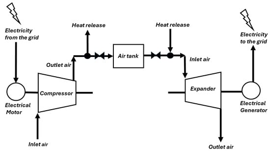
Figure 1.
Architecture of a conventional CAES power plant.
1.1.2. Twin-Screw Volumetric Machines
Twin-screw devices are volumetric machines serviceable for compression and expansion processes. Screw compressors operate in fuel cells, high-temperature heat pumps, and refrigeration systems [7], while screw expanders are used in ORC plants, trilateral flash cycles, fuel cell stacks, and gas pressure stations to recover the natural gas energy pressure [8]. Generally, in a twin-screw device, a pair of helical screw rotors within a casing mesh with each other, thus generating several working chambers bounded by the screw surfaces and the casing. As the screws rotate, the volume of each working chamber increases from a minimum to a maximum value and then decreases. As a result, a twin-screw compressor draws a gas to compress it when the volume of the working chamber progressively decreases [9]. Twin-screw compressors may be either oil-free or oil-flooded. In an oil-free compressor, known as a dry compressor, the screws are not lubricated, and the synchronous motion of the rotors relies on the meshing of timing gears that are placed outside the working chamber [9]. In oil-free compressors, the oil lubricates the timing gears responsible for the synchronization of the screws to ensure a reliable operation. For this reason, oil-free compressors require internal sealing systems placed on each shaft between the working chamber and the bearings to prevent the contamination of the compressed gas with the oil [9]. Conversely, in an oil-flooded compressor, also called a wet compressor, the male rotor screw directly meshes the female rotor and drags it by a thin oil film. As a result, this lubrication ensures smooth motion of the rotors, reduces wear, cools the compressed gas, reduces leaks, and lubricates the bearings. Nonetheless, the presence of the oil requires the use of some additional components to ensure the reliable and effective operation of the compressor. Specifically, the oil must be separated from the compressed gas downstream of the discharge port to obtain clean compressed gas after the compression process. Moreover, the separated oil must be cooled to ensure that its lubricating properties are suitable before the successive injection in the compressor. Therefore, these requirements indicate that a gas cleaning system and an oil cooler are essential when using an oil-flooded compressor. As a result, the injected oil is a crucial parameter that impacts the performance of an oil-flooded twin-screw compressor.
The literature analysis suggested that numerical and experimental works about the oil injection in twin-screw compressors have been proposed in the past decades by several researchers. Singh and Bowman [10] provided a numerical model to predict the influence of the oil droplets on the compressor performances. Then, Basha et al. [11] pointed out that an optimum injected oil quantity can reduce the absorbed power without penalizing the efficiency. Wu et al. [12] described a different oil injection arrangement to improve the performance of a twin-screw refrigeration compressor. At the same time, other studies [13,14,15,16,17] proposed water or vapor injection as an alternative lubricant for twin-screw compressors because the oil may contaminate the compressed fluid. Another factor that influences the operation of twin-screw compressors is the design of the inlet and discharge ports. Guerrato et al. [18,19] experimentally investigated the airflow through the discharge port of a screw compressor and concluded that the rotor motion determines the velocity of the fluid when the pressure gradients are smaller. Read et al. [20] introduced a mathematical model to analyze the impact of the ports and fluid leakages on the operation of a screw compressor. These authors stated that the working conditions and geometry of the rotors determine the pressure on the end-face discharge port shape. Tian et al. [21] calculated the pressure distribution in the end face of a twin-screw steam compressor to predict the leaks of shaft seals by discussing the impact of several parameters.
The use of twin-screw machines as expanders has also become attractive for microgeneration purposes because of their compactness, their acceptable efficiency, and the possibility to tolerate liquid droplets as occurs in wet expansion [3,22,23,24,25]. In the literature, Tang et al. [26] validated the numerical model of a twin-screw expander with four lobes for the male rotor and six lobes for the female rotor that was designed for a geothermal organic Rankine cycle. The results indicated that an increase in the rotating speed from 1250 to 6000 rpm reduced the isentropic efficiency from 0.88 to 0.60 and the volumetric efficiency from 0.88 to 0.70. Wang et al. [27] experimentally investigated three different water-cooled dry oil-free twin-screw expanders for energy recovery in fuel cells. The study aimed to assess the performance of these devices by varying their rotating speed and suction pressure. The maximum power delivered by one of these machines was around 3 kW, depending on the operating conditions. Wang et al. [27] concluded that an enlargement of the suction port decreased pressure losses and that an optimized rotor length could prevent over-expansion. Later, the same research group performed an experimental investigation to discover the indicated cycles of a twin-screw expander, thus identifying the main aspects that determine the operation of the machine [28]. In another work, Tian et al. [29] proposed a numerical model to assess the performance of a twin-screw steam expander with a theoretical displacement per rotation of 0.0012 m3 and a rotating speed between 3000 and 7000 rpm. Their results stated that the filling factor ranged from 0.82 to 0.88, and the isentropic efficiency fell between 0.73 and 0.83. Yao et al. [30] tested a twin-screw expander under off-design conditions using air as the working fluid to introduce two empirical models that predicted the inlet volumetric flow rate and isentropic efficiency. Bianchi et al. [31] numerically investigated a twin-screw expander in a trilateral flash cycle based on R245fa as a working fluid. They found that the volumetric efficiency ranged from 0.248 to 0.612, while the adiabatic one was between 0.376 and 0.831. Nikolow and Brümmer [32] proposed a study to assess the mass flow rate in water-flooded twin-screw machines, thus also including expanders. Additionally, Wang et al. [33] conducted a numerical study to enhance the performance of a twin-screw expander by using a two-phase expansion of air and liquid water. At the same time, a review paper by to Francesconi et al. [34] identified screw expanders as the most promising machines that were suitable for the expansion of two-phase flows.
1.2. Scope of the Paper
The previous literary analysis suggested that most studies discuss the behavior of screw machines when exclusively tested as compressors or expanders. As a result, the need to conduct research about their reversible operation may be attractive to reduce both capital expenditure and operating costs for those energy technologies in which compression and expansion processes occur alternatively, such as Carnot batteries or CAES systems [35,36,37]. In detail, to the best of the authors’ knowledge, the literature seems to lack experimental research about the reversibility of twin-screw machines. Therefore, twin-screw compressors operated in the reversible mode (compressor/expander) by using air as a working fluid are of primary interest. Although oil is paramount to ensure an acceptable operation, the tests show that the expander can operate as an almost oil-free machine, thus highlighting the possibility of a reversible usage of the same device in an energy system such as a micro-CAES without an increase in operating costs. Moreover, the choice to test the expander as an almost oil-free device highlighted the worst performance decay in the switching from operation as an oil-flooded compressor, thus allowing a prudent assessment of the performance reduction. The collected experimental results appear profitable to pursue two scopes:
- -
- Highlight the limitation of the tested technology when run as a dry expander with air, rather than as an oil-flooded machine;
- -
- Develop black-box models of the compressor and the expander, which allows ascertaining the performance of hypothetical systems, such as (but not limited to) a small-scale CAES system based on the reversible operation of the tested screw machines.
Therefore, the novelty of this work is that it provides an experimental analysis of a commercial twin-screw volumetric machine in reversible operation (compressor + expander) by using air as a working fluid. This attempts to fill the research gaps highlighted in Section 1.1.
The paper is organized into the following four sections, namely “Experiments: Materials and Methods” (Section 2), encompassing all experimental setup description, direct measurements details, as well as correlations for indirect measurements; Results (Section 3) of the twin-screw machine operated as a compressor and as an expander; Discussion (Section 4) to understand the relevance of the present study in the framework of micro-CAES technologies and show a potential implementation of the experimental data collected in an energy storage unit; and Conclusions (Section 5).
2. Experiments: Materials and Methods
This section provides a detailed description of the experimental setup, the measurement instruments, the direct and indirect approaches to retrieve relevant information for the twin-screw machine characterization, and its implementation into micro-CAES systems. The thermodynamic concepts for the indirect characterization are well described in Appendix A, while Appendix B clarifies the calculation methodology related to the implementation in a micro-CAES system.
2.1. Description of the Geometry of the Compressor
The tested machine was a commercial oil-flooded twin-screw compressor designed for an electrical power of 3 kW (Figure 2). The inlet port was perpendicular to the axes of the screw rotors, while the outlet port was parallel to it. Consequently, in the compressor operation, the inlet fluid enters perpendicularly to the axis of the machine, fills the operating chambers, and then flows outside along the axial direction.
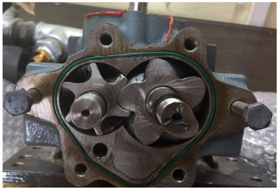
Figure 2.
View of the rotors and their profiles of the oil-flooded twin-screw compressor investigated in the tests.
The reversible usage of the twin-screw compressor as an expander requires that its inlet and outlet ports become the outlet and inlet ports in the expander operation, respectively.
In detail, this machine lacked a slide valve. Casings and male and female screws were made of carbon steel. This device employed 83 mm-long rotors, in which the male and female screws had 5 and 6 lobes, respectively. The meshing resulted in several working chambers, each with a displacement of 25 cm3. All geometric features of the machine are presented in Table 1. The casing accommodates a port settled for oil injection. The injected oil allows the male rotor to directly drive the female rotor without using gears, lubricates the moving parts, reduces leaks, and cools compressed air.

Table 1.
Geometry of the investigated twin-screw machine.
2.2. Test Bench Layout
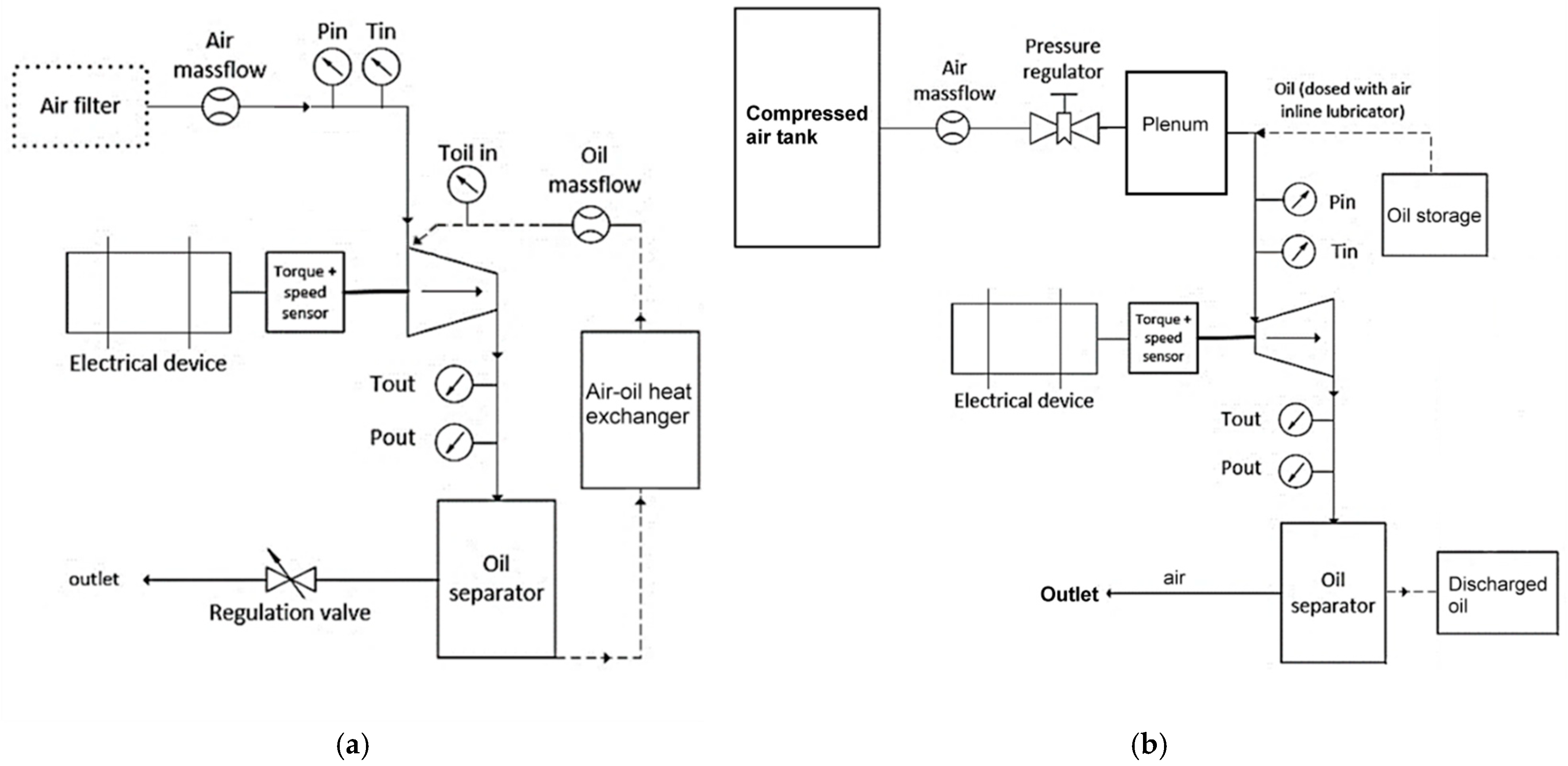
The experiments required a customized test bench allowing the device to operate in both modes, as depicted in Figure 3 (Figure 3a “compressor mode”; Figure 3b “expander mode”). In both operating modes, no gearbox was employed. Such apparatus included components for the reversible management of fluid and power flows and other auxiliary parts, namely:
- -
- An electrical DC machine that worked both as a motor and a generator.
- -
- Pipelines equipped with valves.
- -
- Pressure regulation system (in the compressor mode. The adjustment of the discharge pressure relies on a valve downstream of the device, while in the expander mode, the pressure of the air is regulated by a pressure regulator upstream of the inlet port of the device).
- -
- A 1 m3-volume plenum between the pressure regulator and the expander to damp the unavoidable pressure fluctuations.
- -
- Air filter, necessary to clean the environment air before compression.
- -
- Compressed air storage tank.
- -
- A separate oil circuit to ensure the proper operation of the compressor as an oil-flooded machine: it consists of a pipeline, an air–oil separator, and a heat exchanger to inject, collect, and cool the oil. The use of a circulation pump is not mandatory because the discharge pressure provided by the compressor ensured the oil circulation through the whole circuit.

Figure 3.
Schematic diagram of the experimental test-rig developed to investigate the reversible use of the twin-screw device as a compressor (a) and as an expander (b). Solid lines represent air streams, dashed lines represent lubricant oil streams. The arrows give the flow direction.
Figure 3.
Schematic diagram of the experimental test-rig developed to investigate the reversible use of the twin-screw device as a compressor (a) and as an expander (b). Solid lines represent air streams, dashed lines represent lubricant oil streams. The arrows give the flow direction.
Lubrification oil management is crucial to guarantee an effective operation because it reduces friction losses and leaks through the gaps of the working chambers, thus ensuring a regular compression process. The correct operation of the oil circuit is of outmost importance to ensure a successful and safe operation of the compressor, thus requiring to maximize the injected oil flow rate. Therefore, this demand compels a proper design, arrangement, and adjustment of the oil circuit to reduce pressure drops as much as possible.
Conversely, the experimental tests in the expander mode were performed under poor lubrication conditions to assess the operation of the device as an almost-dry expander. In detail, on the one hand, the scarce lubrication penalized the efficiency and increases leaking phenomena, while on the other hand, it allowed the assessment of the reversible operation of the oil-flooded twin-screw compressor, as suggested by the following aspects:
- -
- The lack of a significant oil injection implied that the expander operated under unfavorable conditions, such as higher friction and leaks, thus demonstrating the potentiality to recover wasted energy without modifying the geometry of an existing compressor and reducing the investment and operating costs.
- -
- Poor lubrication entailed fewer difficulties during the operation of the expander because of a simplified design of the oil circuit and the lowest contamination of the working fluid [3].
- -
- The operation of the same device as an almost-dry expander and as a wet compressor provided the maximum variations in the performances between these two operating modes that otherwise would not be shown by using the expander as a wet machine.
Therefore, to test the device as an almost oil-free expander, it was essential to seal the oil injection port in the casing and introduce a lubricator upstream of the device to inject a few drops of oil into the incoming air, thus preventing potential damage to the rotor bearings. As a result, the device operates in almost-dry and not strictly dry conditions. The slight amount of oil injected was considered sufficient to avoid damage during the test, yet it did not provide any noticeable sealing effects, as it currently happens in oil-free devices. As already stated, this was the aim of the present work, but it is noticeable that a better performance may be exhibited by the same device if tested as an oil-flooded expander because the higher injected oil quantity decreased the leaks and friction losses.
2.3. Measurement Equipment and Direct Acquisitions
The test bench was equipped with the following measurement instruments:
- -
- Thermocouples upstream and downstream of the machine (Type T, accuracy of 0.5 °C, and operating range from −40 °C to +350 °C);
- -
- Pressure sensors upstream and downstream of the machine (Aventics Series PE6, piezoresistive sensors, FSS ± 3%, and operating range of 0–10 bar, manufactured by EMERSON, website https://www.emerson.com/en-us);
- -
- A flowmeter to measure the air mass flow rate processed (VPflowScope thermal mass flow rate sensors, ±0.5% FSS (0 … 60 °C), and operating range of 0.23 … 80 m3/h produced by VPinstruments, Marlotlaan 1G 2614 GV The Netherlands, website https://www.vpinstruments.com);
- -
- A torque sensor between the twin-screw compressor and the electrical machine, whose rotating speed control depends on a dedicated driver (Kistler type 4503A, rated torque of 0.2 … 5000 Nm, speed ranges up to 50,000 rpm, and accuracy class in standard measuring, developed by Kistler, website https://www.kistler.com).
Moreover, an acquisition system NI 9201 cDAQ registered all the signals every 50 ms and a LabVIEW-based code conducted the measurements with a time buffer of 3 s. The instruments were calibrated according to the providers’ datasheet requirements. The instruments’ accuracy was complemented by the high-frequency acquisition. Therefore, the direct measurements available from the test bench during the tests of the compressor and the expander were reported in the following Table 2.
Table 2.
List of the direct measurements available from the test bench during the tests of the compressor and the expander. The subsctripts “c” and “e” referred to the compressor and expander modes, respectively.
2.4. Indirect Measurements
The direct measurements obtained in the tests can be manipulated to obtain a set of indirect measurements that extend the analysis of the compressor and the expander. In detail, an in-depth analysis of both operating modes should include the acquisition of the pressure inside the working chamber. Nonetheless, this measurement appeared practically unachievable in the tests of the investigated device because its reduced dimensions result in small operating chambers that rotate and translate along the axes of the machine, thus complicating the acquisition of the signal pressure. Therefore, the aim to overcome this limitation and obtain a comprehensive analysis led to us considering a fictitious polytropic process that reasonably represents the actual thermodynamic process performed by the device with the advantage of an easier mathematical description [38]. Although the use of this fictitious process is solely a conceptual tool that does not provide the same thermodynamic data compared to in-chamber pressure, it appears still practical for the analysis of the two operating modes of the device, especially regarding dissipative effects. This last consideration implies that the fictitious polytropic process mathematically replaces the tested twin-screw device with another equivalent machine whose operation occurs in the same experimental operating conditions and provides the same performances detected in the tests. The integration of the fictitious polytropic process and the experimental data allows formulating energy balances leading to a comprehensive overview of results. As a result, the outcomes of this analysis consist of a series of indirect measures that are obtained by using the direct measurements provided by the test bench and the fictious polytropic model (detailed in Appendix A).
2.4.1. Compressor Characterization
The characterization of the compressor relies on Equations (1)–(6) that rely on direct measurements of the operating conditions acquired by the test bench and the polytropic index that is an indirect measurement obtained from Equation (A1) in the Appendix A. The absorbed mechanical power by the compressor is found as the product between torque and rotating speed of the male rotor, as in Equation (1). Equation (2) provides the term that represents the power dissipations of the compressor due to frictions in the mechanical parts and turbulence. The displacement fraction in Equation (3) is a parameter that relates the geometry of the compressor and its polytropic behavior to the imposed compression ratio. The heat transfer experienced by the compressor is calculated by Equation (4), where represents the heat loss through the casing. At the same time, Equation (5) expresses the overall compression efficiency as a function of polytropic index pressure ratio , oil to air mass flow ratio, air mass flow rate, and dissipative term The analysis of the volumetric performance is provided by the volumetric efficiency in Equation (6) that compares the real mass flow rate processed by the device with the theoretical mass flow that such a compressor might process in the same operating conditions.
2.4.2. Expander Characterization
The set of Equations (7)–(11) describe the operation of the twin-screw device as an oil-free expander. These calculations are obtained by combining the direct measurements of the operating conditions with the polytropic index , which is an indirect measurement whose value is expressed by Equation (A13) in the Appendix A. Equation (7) indicates the calculation of the power delivered by the expander. Equation (8) estimates the dissipations due to friction and turbulence mechanisms, summarized by the term The thermal behavior of the expander in terms of heat losses through the casing is described by in Equation (9) to consider the impact of heat transfer on the operation. Equation (10) provides the overall isentropic efficiency by highlighting its dependence on the dissipation , operating conditions, and polytropic index . The filling factor in Equation (11) assesses the volumetric performance of the expander by comparing its mass flow rate with the mass flow rate processed by an ideal expander with same geometry and operating conditions.
2.5. Design of Experiments
The experimental tests aim to assess the potential operation of the commercial device in the reversible operation, thus judging its suitability for this matter with minimal adjustments. For this reason, the tests were performed by varying the rotating speed and the pressure ratio that behave as independent variables. Table 3 shows the test matrix.
Table 3.
Design of the experiments: test variable combination ( is a compression ratio, while is an expansion ratio).
The tests investigated rotating speeds up to 5000 rpm, although twin screw devices may operate up to 8000–10,000 rpm [28,38]. However, these latter values are considered too high to assess the operation of the tested compressor as an expander, especially in conditions of poor lubrication and in the absence of appropriate modifications. Therefore, a range of rotational speeds between 2000 and 5000 rpm appeared suitable to test and compare the device in both working modes without suffering possible failures. As a result, the selected rotational speeds resulted in tip speeds of the male rotor between 6 and 14 m/s. These values appear acceptable for the aim of this work, as suggested in the literature, in which some studies investigated the operating screw compressors for tip speed values between 10–60 m/s [39] and 9–20 m/s [40]. The tested pressure ratios were 5, 7, and 9, where the ambient pressure (1 barA) was alternatively suction and discharge pressure depending on the operation mode of the device. In all the reported cases, the upstream air temperature was between 24 and 25 °C. The resulting test matrix is shown in Table 3. Therefore, the other variables (temperature, air mass flow rate, oil mass flow rate, and torque) were measured in each operating condition by means of the measurement instruments. The acquisition process occurred when the device reached steady operation.
2.6. Micro-CAES Model
The previous subsections established indicators to manage the experimental data to assess the device’s performance as an oil-flooded compressor and a dry expander. However, additional calculations are necessary to evaluate the operation of this device in a potential micro-CAES system. Therefore, this task requires the prior identification of a suitable operating mode for the CAES system, which can be summarized in the following steps:
- -
- When an energy surplus is available, the device works as an oil-flooded twin-screw compressor to suck ambient air and compress it up to a given pressure, thus charging the reservoir (charge process);
- -
- The compressed air is then cooled to become isothermal with the surrounding environment. As a result, the compressed air is stored in the reservoir at the ambient temperature and a given pressure;
- -
- When energy production is required, the compressed air in the tank is first heated up to a specified temperature at the same pressure and then expanded in the device that works as a dry-running expander (discharge process).
Therefore, the available experimental data allow the assessment of the performance of the tested device in a hypothetical CAES system working under the same pressure ratio as that in the experiments. Nonetheless, in the CAES operation, the air in the storage is heated just before the discharge process, and this fact implies that the air temperature in this hypothetical CAES is higher than the corresponding temperature of stored air in the tanks measured during the expander test. As a result, this difference would cause a discharged mass flow rates through the expander in the CAES operation that would differ from the corresponding values measured in the experimental test of the expander. Therefore, the strategy to address this issue requires calculating correction parameters to modify the direct experimental measurements, thus adjusting them to the operating conditions that would exist in the discharge process of the hypothetical CAES. As a result, the adjusted value of the power delivered by the expander is noted and it is based on the specific real work . The key parameters derived from the experiments, and thereby, considering the effect of real operating conditions, are (for the sake of conciseness, the full algebraic model is reported in Appendix B, together with a brief thermodynamic explanation):
- -
- CAES unitary roundtrip efficiency which exclusively assesses the behavior of the tested twin-screw machine in this hypothetical CAES system without considering the filling and emptying process of the reservoir. is expressed by Equation (12), in which the compression work per unit is calculated by considering that the compressor processes both air and oil.
- -
- Power ratio (PR, Equation (13)), expressing the percentage of the delivered power during the real discharge process with respect to the requested power in the charge process.
The filling and emptying processes depend on the reservoir dimensions, which determine the storable air mass under specific thermodynamic conditions. For this reason, the use of quantities defined per unit of mass in the unitary round-trip efficiency avoids the need to model the storage behavior and allows estimating the losses that occur from the recovery of energy during the compression up to the following conversion into useful energy based the heating and expansion processes.
3. Results
This section presents the experimental outcomes of the reversible twin-screw machine. In detail, Section 3.1 shows the experimental outcomes regarding the compressor operation mode, and Section 3.2 provides the evidence concerning the expander characterization. The results are reported by showing their mean values with standard deviations calculated on the acquired sample. The operating maps of both operating modes show the air mass flow rate as the abscissa and the pressure ratio as the ordinate because this arrangement improves their readability and is consistent with the representation of the operating maps of other systems, such as compressors and turbines. Conversely, the other diagrams show the trend of direct and undirect measurements as a function of the pressure ratio and rotating speed that represent the operating parameters.
3.1. Experimental Results of the Working Mode as a Compressor
The twin-screw volumetric machine was first tested as a compressor.
3.1.1. Direct Measurement: Characteristic Curves of the Compressor
The experimental characterization allowed us to draw the operating map of the compressor. The air mass flow rate is independent from the compression ratio and increased solely with the rotating speed (Figure 4), since in volumetric machines, the mass flow rate exclusively depends on the rotating speed, fluid inlet density, number of working chambers, and displacement of each chamber, according to Utri and Brümmer [41].

Figure 4.
Operating maps of the device tested as an oil-flooded twin-screw compressor in terms of processed air mass flow rate and compression ratio.
Nonetheless, the outcomes depicted in Figure 3 also depend on the injected oil mass flow contributing to the compression process. This requires the discussion of the trend of the oil-to-air mass flow ratio (Figure 5). The results show that the oil-to-air mass flow ratio grows with the compression ratio for a given rotating speed because the discharge pressure increases, thus causing a higher oil flow rate in the circuit and then a higher injected oil quantity at the same air flow rate delivered by the compressor. Conversely, the oil-to-air mass flow rate ratio decreases when the rotational speed grows for a given compression ratio since these conditions increase the air mass flow rate and reduce the leaks without significantly altering the injected oil mass flow rate. The results show that the oil-to-air mass flow ratio varied from 8 to 20, although some peak values were between 28 and 34, thus appearing as exceptional cases. The main reason for these excessive values is probably that the device was operated in a laboratory test rig whose characteristics differed from those of an industrial plant. In detail, the design of the oil circuit to maximize the oil flow mass rate might have caused an extraordinarily high injected oil quantity that resulted in extreme values of the oil-to-air mass flow ratio. This effect was particularly relevant during the operation at 2000 rpm when the compression ratio increased from 5 to 9 because these working conditions caused the lowest air mass flow (reduction from 4.5 × 10⁻³ to 4.0 × 10⁻³ kg/s) and the highest oil flow rate (from 30 to 32), thus resulting in tremendous oil-to-air mass flow ratios (Figure 5).
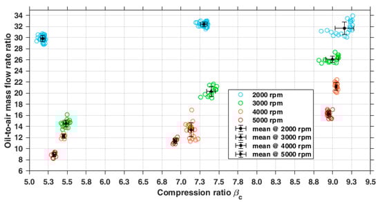
Figure 5.
Trend of the oil-to-air mass flow rate ratio detected in the compressor operating mode as a function of the rotating speed and compression ratio.
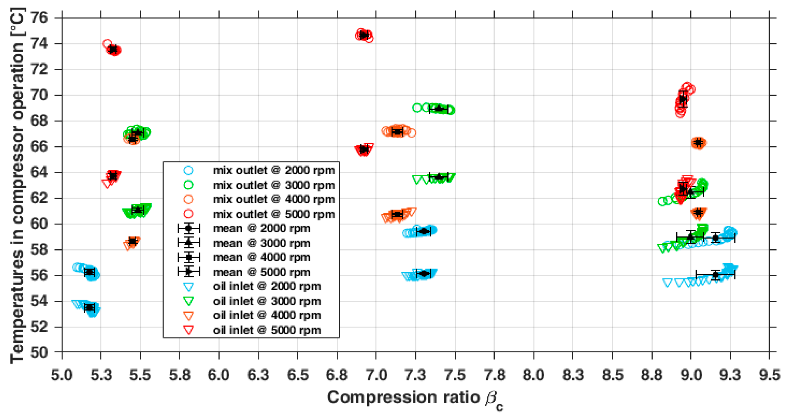
Additionally, an excessive oil quantity in the working chamber diminished the volume available to trap air, thus having the same effect of a displacement reduction that entailed a decrease in the air mass flow rate through the compressor [12] (see Equation (A16) in Appendix A). In percentage terms, these variations indicated that the mass flow rate decreased by about 11.5% and that the oil-to-air mass flow ratio grew by around 6.7%. A comparison with the literature shows that the air-oil mass flow ratio is usually in the range of 2–5 [11,42,43], even if other authors reported a value of 12 [44]. The main difference in these values from the literature depends on the operating conditions, machine design, and system layout in which the compressor works. According to these considerations, the oil-to-air mass flow ratio values presented in this work still seemed acceptable as their order of magnitude falls between 1 and 10, thus matching the values from the literature. The oil injection and the operating conditions of the compressor determined a discharge temperature of the air–oil mixture in the range of 56–74 °C (Figure 6). The injected oil affected the discharge temperature of the air–oil mixture because its specific heat (ca. 1800 ) was higher than air’s specific heat (1004 ). As a result, higher oil-to-air mass flow rate ratio values limit the temperature increase in the air–oil mixture because the oil curbs the heating process by absorbing heat from the air. Moreover, the oil heating due to the compression process is marginal because of the oil’s weak compressibility. In general, the results reveal that the growth in the rotating speed at the same compression ratio increases the temperature of the air–oil mixture produced by the compressor. This behavior depends on the following reasons:
- -
- Higher density of the fluid in the working chamber due to leak reductions, as a consequence of the increased rotating speed;
- -
- Greater air mass flow rate and, at the same time, decrease in the oil-to-air mass flow rate ratio, thus suggesting that the injected oil may not be sufficient to cool adequately the increased air mass within the device.
Conversely, the discharge air temperature decreases weakly with the rise in the compression ratio at the same rotating speed. This trend depends on the higher injected oil quantity caused by the compression ratio rise that improved the cooling process of the compressed air mass flow rate, whose value is constant since the rotating speed remained unaltered (Figure 6).
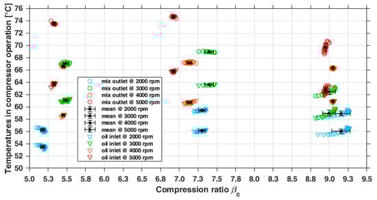
Figure 6.
Temperature of the oil and air at the inlet of the compressor and temperature of the oil–air mixture acquired downstream of the discharge port of the compressor. The data are reported in terms of the compression ratio and rotating speed.
Figure 6.
Temperature of the oil and air at the inlet of the compressor and temperature of the oil–air mixture acquired downstream of the discharge port of the compressor. The data are reported in terms of the compression ratio and rotating speed.
3.1.2. Indirect Measurements: Performance Parameters of the Compressor
From the torque measurement, absorbed power curves were derived. The results indicate that the compressor requires a mechanical power in the range of 1–3 kW, increasing with the rotating speed and pressure ratio (Figure 7). A rotating speed increase at the same compression ratio causes a higher mass flow rate through the device, thus requiring much more power for the compression. Conversely, the compression ratio growth for a given rotating speed causes a rise in the input mechanical power because of the need to reach a higher discharge pressure. Nonetheless, higher mass flow rates and pressure ratios also involve higher friction losses in bearings, seals, and turbulence dissipation, thus causing the growth in power dissipation () [45,46,47] (Figure 8). The experimental results suggest that the trends of mechanical input power and dissipations vary more or less linearly with the compression ratio and rotating speed.
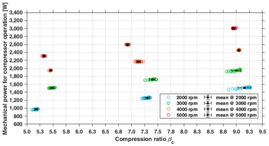
Figure 7.
Mechanical power requested at shaft by the device in the compressor operating mode.
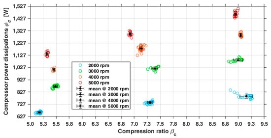
Figure 8.
Trend of dissipative effects due to frictions and turbulence obtained from the experimental data of the compressor operating mode for different compression ratios and rotating speeds.
As a result, the overall compression and volumetric efficiencies (Figure 9) also change because the pressure ratio and rotational speed affect leaks, pressure drops through the ports, and injected oil quantity. Depending on the compression ratio, the overall compression efficiency exhibited the two following trends:
- The lowest : the efficiency monotonically decreases from 0.8 to 0.6.
- Intermediate and the highest the overall compression efficiency is almost constant in the range of 2000–3000 rpm and then decreases to 0.6 while the rotating speed grows.
In detail, an increase in the pressure ratio at the lowest rotating speed (2000 rpm) gradually reduces the overall compression efficiency from 0.82 to 0.70 because the consequent excessive increase in the injected oil quantity involved a higher oil-to-air mass flow rate ratio that decreased the overall compression efficiency (Equation (5)). Conversely, at the intermediate and higher pressure ratios, the overall compression efficiency is almost constant with the initial growth in the rotating speed from 2000 to 3000 rpm since the subsequent mass flow rate increase reduces the oil-to-air mass flow ratio without a considerable growth in dissipative effects. As a result, these conditions ensure that the overall compression efficiency remains almost constant (Equation (5)). However, as soon as the rotation speed increases above 3000 rpm, the dissipative term in Equation (2) prevails over the growth in the air mass flow and leak reduction, thus decreasing the overall compression efficiency. A comparison with the literature suggests that these trends are mostly compatible with those of other studies [38,40,48].
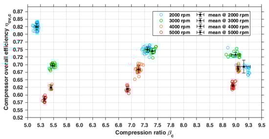
Figure 9.
Trend of the overall compression efficiency evaluated in the compressor operating mode in terms of the pressure ratio and rotating speed.
Figure 9.
Trend of the overall compression efficiency evaluated in the compressor operating mode in terms of the pressure ratio and rotating speed.
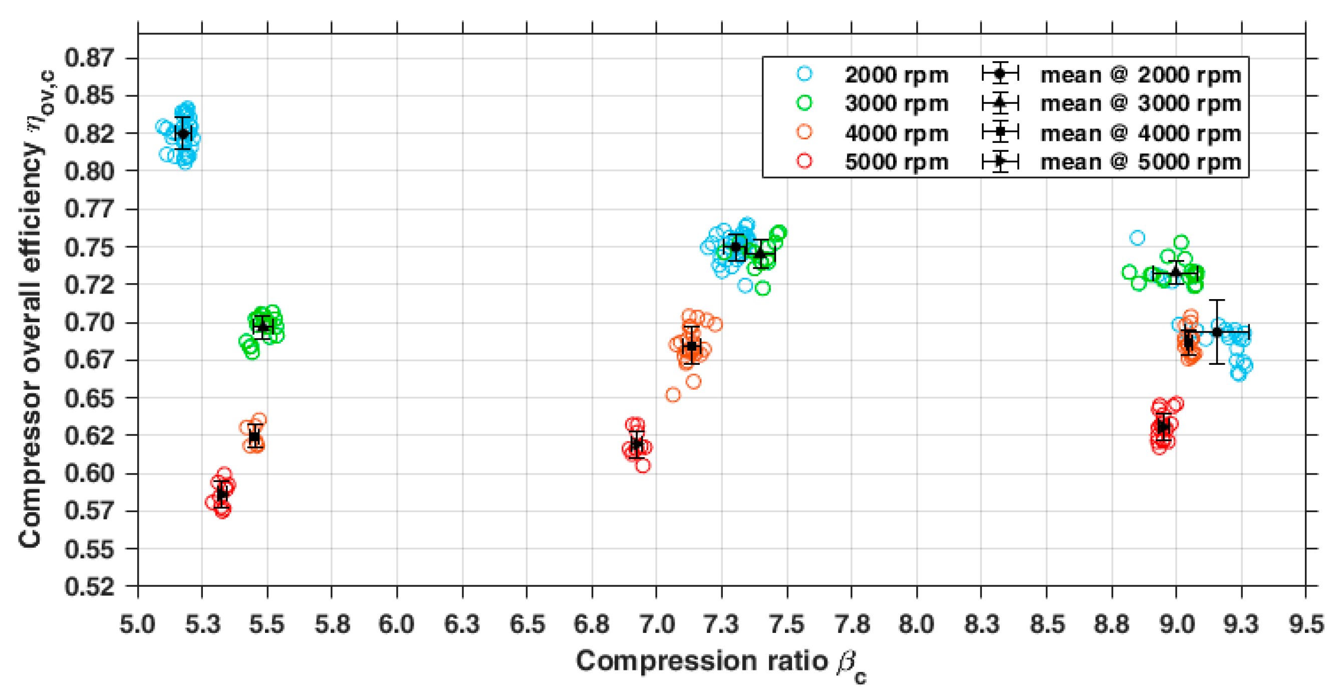
The results indicate that the volumetric efficiency depends on the pressure ratio and rotating speed. In the whole operating range, the volumetric efficiency remained lower than 1 and ranged from 0.6 to 0.9, thus implying that the actual mass flow rate was smaller than the expected theoretical value for two main reasons. Firstly, the throttling losses through the inlet port decreased the air density, thus reducing the air mass flow rate. Secondly, the oil injection combined with a low rotating speed, resulted in an improper oil distribution along the periphery of the working chamber. This uneven oil distribution was insufficient to completely seal the gaps in the chamber, where leaks could occur. Consequently, the pressure difference within the device led to a series of internal leaks through these unsealed gaps. These leaks gradually flow within the device from the chambers at a higher pressure toward the suction port, thus partially filling the working chamber involved in the suction process and causing a decrease in the air drawn outside the compressor. In detail, two main trends of the volumetric efficiency can be observed by varying the rotating speed and compression ratio (Figure 10). For a given compression ratio, the volumetric efficiency decreased with the rise in the rotating speed. On the one hand, this behavior entailed a leak reduction because of the improved oil distribution in the periphery of the working chamber and the lower time available for the fluid to escape through the gap. However, a higher rotational speed at the same compression ratio entailed an increase in the air volume flow rate through the suction port. Therefore, this fact resulted in a higher air velocity that increased the pressure losses, thus reducing the air density and the consequent decrease in the air mass flow rate delivered by the compressor. Conversely, the volumetric efficiency moderately varied with the compression ratio when the rotating speed remained constant. In detail, the compression ratio determined the injected oil quantity that, in turn, sealed the gaps, thus affecting the leaks. The results indicate that the volumetric efficiency at 2000 rpm decreased from 0.9 to 0.8 as the compression ratio increased because these operating conditions resulted in the highest values of the oil-to-air mass flow rate ratio (Figure 5). Therefore, this situation implies that the excessive injected oil quantity diminishes the in-chamber volume available in the suction process to trap the mass of incoming air [12], thus reducing the volumetric efficiency. However, this behavior practically disappeared when the rotating speed was higher than 3000 rpm because the rise in the air mass flow rate due to the higher rotating speed prevailed on the injected oil mass flow rate, thus decreasing the corresponding oil-to-air mass flow rate ratio (Figure 5). A comparison with the literature suggests that the proposed trend of the volumetric performance of the tested compressor presents some discrepancies with those in other studies, in which the volumetric efficiency grew with the rotating speed [38,40,48,49]. The probable reason for this difference is due to the excessive injected oil quantity employed in these tests and the choice of rotating speeds being lower than those currently employed in the operation of twin-screw compressors, whose values can be up to 10,000 rpm. However, the volumetric efficiency found in this work was between 0.90 and 0.60, thus matching the values reported in the previous literature [38,40]. The trend of the displacement factor found by Equation (3) decreased with the growth in the compression ratio and appeared to be slightly influenced by the rotation speed. The main reason was that a higher compression ratio required a greater swept volume to increase the final pressure, thus gradually reducing the final volume of the air–oil mixture as the pressure ratio grew (Figure 11). At the same time, the calculation of the thermal losses through the casing case (Equation (4)) revealed that these latter ones grew with the rise in the pressure ratio and the rotational speed (Figure 12). In detail, an increase in the rotating speed and pressure ratio caused a higher discharge temperature of the air–oil mixture, thus suggesting a rise in the temperature difference between the compressed fluid within the device and the environment. As a result, heat losses grew because they were directly proportional to this temperature difference. At the same time, the rise in rotating speed also affected the heat losses through the casing case by two additional effects that were contrasting. On the one hand, higher rotational speeds intensified the turbulence that caused a higher coefficient of the air–oil mixture in the compressor, thus increasing heat loss. On the other hand, the rise in rotating speed reduced the time required for the heat transfer process because the air–oil mixture flowed faster through the machine, thus mitigating the heat loss. However, the results suggest that the operation at the higher rotating speed predominantly increased heat losses (Figure 12). The heat losses were 37% of the mechanical power absorbed by the compressor at the highest rotating speed and pressure ratio. Conversely, the operation at the minimum rotating speed and pressure ratio decreased this to 1%.
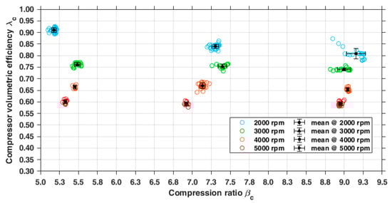
Figure 10.
Volumetric efficiency calculated in the compressor operating mode as a function of the pressure ratio and rotating speed.
Figure 11.
Displacement fraction of the device in the compressor operating mode to compress the air under a given compression ratio.
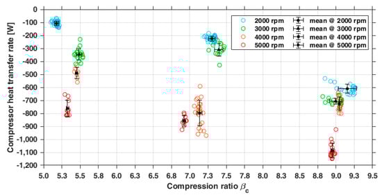
Figure 12.
Thermal losses through the housing of the device in the compressor operating mode as a function of the pressure ratio and rotating speed.
3.2. Experimental Results of the Working Mode as an Expander
Then, the twin-screw volumetric machine was experimentally investigated as an expander by switching some valves of the pneumatic circuit to introduce the compressed air through the discharge port of the compressor.
3.2.1. Direct Measurement: Characteristic Curves of the Expander
During the tests, the lubrication process was performed by a lubricator that injected 1–2 oil drops (0.03–0.06 g) every 6 s, thus causing an oil mass flow rate of 0.01 g/s that is significantly lower than the air mass flow rate (Figure 13). Therefore, the implementation of this lubrication confirmed that the expander operated as an almost oil-free device. In these operating conditions, the poor lubrication and the lack of modifications resulted in a thorough assessment of the cost-effectiveness and technical feasibility of the reversible operation of the oil-flooded compressor as an almost-dry expander. Unlike the compressor, the relation between the expansion ratio and the mass flow rate through the expander appeared as a series of curves and not straight lines (Figure 13). The main reason for this different trend depends on the leaks, whose magnitude was significant because of the scarce seal effects due to the lower injected oil quantity. In the expander operation, the air flowed within the device from the highest pressure to the ambient pressure by following an opposite path compared to the compressor. In the suction process, the compressed air from the plenum entered through the inlet port of the expander, thus filling working chambers whose boundaries were shaped by the surfaces of the screws. Part of this incoming air leaked outside the working chambers through the rotor tips, seal line, and blow-hole area because the injected oil was not entirely sufficient to seal these passages. At the same time, the remaining trapped air exerted a pressure distribution on the surfaces of the several working chambers, thus causing the rotation of the rotors and the mechanical shaft. As the rotors turned, the shape of each working chamber changed and increased its volume while moving along the expander, thus causing the expansion process.
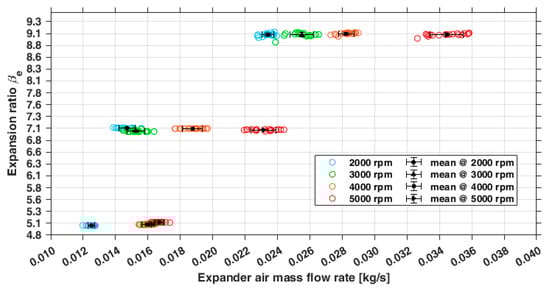
Figure 13.
Operating maps of the device tested as a dry-running twin-screw expander in terms of the delivered air mass flow rate and expansion ratio.
These considerations suggested that the poor lubrication and the large tolerances between helical rotors and the housing induced significant leaks through the following gaps:
- -
- Among adjacent working chambers;
- -
- Along the casing between the inlet and exhaust ports because of the complete bypass of the working chambers.
These leaks increased the flow consumption because they partially emptied the volume of working chambers, thus drawing back additional incoming air to replace the fluid lost in the leaks. Therefore, the rise in the expansion ratio resulted in a higher pressure difference through the device, and the main consequence was a nonlinear increase in the mass flow rate (Figure 13).
Moreover, the leaks impacted the temperature of the air exhausted outside through the discharge port. This behavior occurred because the leaks did not participate in the expansion process but underwent a slight drop in temperature as they passed through the device. Conversely, the air trapped in the working chambers experienced an expansion process, and the consequence was that its final temperature diminished as the expansion ratio increased. At the end of the expansion and just before the discharge port, the leaks came in contact with the expanded air outgoing from the working chambers. This fact caused a mixing process that resulted in an airflow whose temperature was intermediate between the temperatures of the leaks and the expanded air. The results indicate that this mechanism caused an outlet air temperature between −6 and −30 °C, whose trend mainly decreased with the rise in the expansion ratio and rotating speed (Figure 14). The results also show that the air temperature at the discharge port was constant for values of expansion ratio higher than 7 when the rotating speed was the lowest (2000 rpm). This behavior was due to the existing working conditions that caused higher leaks, whose value overcame significantly the quantity of air processed in expansion. As a result, this effect increased the temperature of the airflow obtained after the mixing process just before the discharge process. Conversely, the discharge temperature diminished with the growth in the expansion ratio at higher rotating speeds because the leaks decreased as the fluid had less time to flow through the gaps and leave the several working chambers. At the same time, these conditions ensured that a higher air mass was trapped in the working chamber to undergo the expansion process. As a result, the mixing process between these lower leaks and the higher mass of the expanded air resulted in an air flow whose final temperature mostly matched the temperature of the expanded air. As expected, the exhaust temperature of the dry screw expander (Figure 14) deviated from that of an ideal expander with entirely sealed operating chambers.

Figure 14.
Experimental discharge temperatures of the air downstream of the discharge port of the expander in terms of the expansion ratio and rotating speed.
3.2.2. Indirect Measurements: Performance Parameters of the Expander
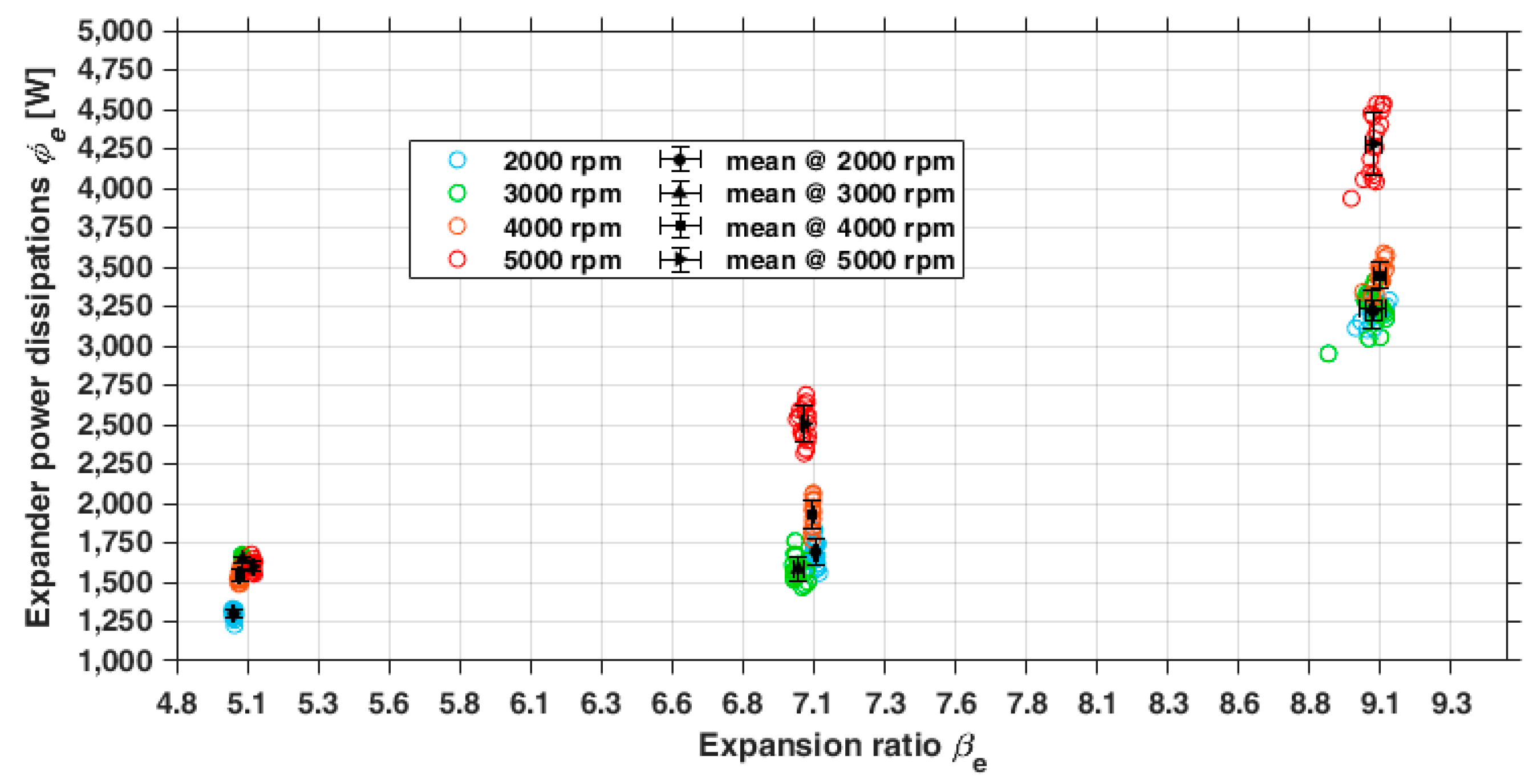
The polytropic exponent of the fictitious expansion process grew slightly with the rotating speed and the expansion ratio, thus showing comparable values to those found in compression but with an opposite trend. This difference probably depends on the different values of leaks and heat exchanges experienced by the device that affected the operation of the expansion process. In detail, thermal fluxes and leaks impacted the specific volume of the trapped fluid and then the corresponding matching with the built-in volume of the device. As expected, the expander-delivered power at the shaft grew linearly with the rotating speed and the expansion ratio (Figure 15) from 300 W up to 1600 W because of the following reasons: (i) under the same expansion ratio, a higher rotating speed implied a higher mass flow rate trapped by the rotors and lower leaks; and (ii) at the same rotating speed, an increase in the expansion ratio caused a growth in the enthalpy drop between the suction and discharge sections.
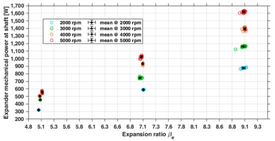
Figure 15.
Mechanical power delivered at shaft by the device in the expander operating mode in terms of the expansion ratio and rotating speed.
Nonetheless, the lack of adjustments to suit the original compressor as an expander led to higher dissipations that varied between approximately two and four times the power output provided by the expander (Figure 16). The main possible causes for these dissipative effects were: a significant friction power dissipated in the bearings because of limited lubrication, high-pressure losses through the suction and discharge ports because of their non-optimal geometrical shapes, and turbulent flows and mixing processes caused by the leaks. Nonetheless, the operation of the expander was additionally affected by:
- -
- Rotor profiles designed for compressor operation and not suitable for the expansion process;
- -
- A mismatching between built-in volume ratio and fluid-specific volume ratio that caused under or over-expansion losses;
- -
- An improper value of the resulting cut-off grade that affected the expansion process;
- -
- Heat transfer due to the lack of thermal insulation.
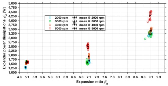
Figure 16.
Trend of dissipations due to frictions and turbulence detected in the expander operating mode for different expansion ratios and rotating speeds.
Figure 16.
Trend of dissipations due to frictions and turbulence detected in the expander operating mode for different expansion ratios and rotating speeds.
The assessment of the thermal exchanges through the casing case revealed that the expander experienced a net thermal flux whose direction was unstable with the operating conditions (Figure 17). As a result, this result contrasted with the discharge temperatures of the air that were lower than the environment. Nonetheless, a possible explanation for this behavior assumed that the air first underwent heating due to the friction dissipations and then a dramatic temperature drop due to the expansion and pressure losses through the exhaust port. This consideration might explain the spread of the values of the net heat flux with the operating conditions and suggest that the lumped parameter model for calculating the heat exchanged through the casing could provide inconsistent results. The results indicate that the absolute value of the percentage ratio of the external heat flux to the shaft mechanical power absolute values ranged from 0.6% to 17% for the expander and between 10 and 43% for the compressor.
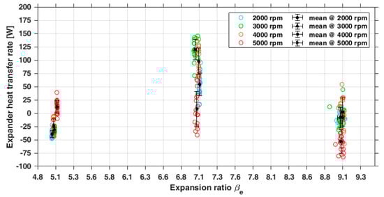
Figure 17.
Thermal losses through the machine housing in the expander operating mode as a function of the expansion ratio and rotating speed.
The test conditions revealed that the expander exhibited an overall efficiency between 0.22 and 0.39, whose trend slightly increased with the pressure ratio for a fixed rotating speed probably up to a maximum expansion ratio of 7 (Figure 18). The highest overall efficiency values occurred around the intermediate expansion ratio probably because the system-specific volume expansion ratio and the internal volume ratio of the device matched in these operating conditions, thus causing a decrease in over- and under-expansion losses. At the same pressure ratio, the overall efficiency mostly grew with the rotating speed. The only exception occurred during the operation under an expansion ratio of 7, in which the overall efficiency diminished for rotating speeds higher than 4000 rpm. The reason for this reduction probably relied on a simultaneous growth in pressure losses and leaks, thus increasing the term that included the dissipation effects (Equation (8)). A comparison indicated that the trend of the expansion’s overall efficiency proposed in this work resembled the trends of efficiency provided in other works about twin-screw expanders [8,28,29,50,51,52,53,54,55]. However, the unavoidable differences between the proposed trend of this work and those in the literature depended on the different geometries of the investigated machines and the operating conditions in which they operated. Apart from these differences, all these studies showed that the efficiencies of twin-screw expanders range from 0.30 up to 0.70 for operating speeds between 900 and 12,400 rpm. Therefore, this consideration suggested that the overall efficiency values exhibited by the expander tested in this work matched the lower efficiencies reported in the literature for similar twin-screw expanders. In addition, another comparison with other expansion systems tested under similar operating conditions indicated that the efficiency of the expander investigated in this work was lower than scroll and Wankel expanders [3,46], whose values were in the ranges of 0.60–0.70 and 0.58–0.85, respectively. At the same time, the literature indicated that other devices, such as single-screw machines, vane expanders fueled with air, and piston systems fueled with CO2, reached efficiencies in the range of 0.20–0.45 [8,24] that were comparable with the values found in the experimental analysis of the investigated expander.
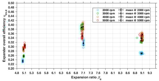
Figure 18.
Trend of the overall expander efficiency in the expander operating mode as a function of the pressure ratio and rotating speed.
The volumetric performance exhibited by the expander was assessed by the filling factor that estimated the efficiency with which the expander filled its operating chambers, thus revealing information about internal leaks and pressure losses in the suction port in which the compressed air entered. The filling factor of the tested expander was higher than 1 in every operating condition (Figure 19) because the true mass flow rate was higher than its theoretical value. The reason for this result was that the working chambers in the suction process received more fluid than the necessary to replace the leaks. In detail, this effect prevailed in the reduction in the mass flow rate due to the throttling losses of the suction port that reduced the density of the inlet compressed air. The results indicate that the highest values of the filling factor occurred at 2000 rpm and varied from 2.5 up to 4, while the lower values were observed at 5000 rpm in a range between 1.2 and 2.5. In most of the operating range, the filling factor grew quasi-linearly with the expansion ratio at the same rotating speed since the rise in the inlet pressure caused a higher pressure difference through the device, thus increasing the leaks. In contrast, the filling factor decreased with the growth in the rotating speed at the same pressure ratio because of the leak reduction. As a result, each operating chamber trapped a higher quantity of fluid, thus requiring less incoming fluid to replenish the amount lost through leaks. However, the reduction in the filling factor with the rotating speed was practically negligible between 4000 and 5000 rpm because of the rise in the pressure losses through the inlet port that reduced the fluid inlet density and then the trapped mass in the working chambers. A comparison with the literature indicated that this study presented a trend of the filling factor that was consistent with that of other works [27,55,56]. The main difference was that the literature provided smaller filling factors as they were between 0.6 and 3.0 because such works analyzed twin-screw expanders with lower leak phenomena. Therefore, these results indicate that the reversible use of an oil-flooded twin-screw compressor as an almost-dry expander entailed a filling factor higher than one because the small injected oil quantity was insufficient to reduce the leaks. In detail, the operating points in which the filling factor was slightly higher than 1 were those with the lowest expansion ratio and the highest rotating speed.
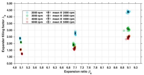
Figure 19.
Trend of the filling factor of the expander represented in terms of the expansion ratio and rotating speed.
4. Discussion
The experimental tests presented in this paper preliminarily demonstrated that the oil-flooded twin-screw compressor could reversibly work as an expander by simply admitting the compressed fluid in its discharge port. The tests also demonstrated that this operation was achievable by implementing a poor lubrication and without adding any modification of the machine. As expected, the operation of the same twin-screw machine as an oil-flooded compressor and as an oil-free expander provided different performances. In detail, the tests indicated that the input power of the compressor was in the range of 1000–3000 W, while the expander delivered an output power in the range of 250–1500 W. This fact implies that compressor requires an input power from 2 up to 4 times the power provided by the expander. At the same time, the expander processed an air mass flow rate that was between 2.7 and 4.8 times the air mass flow rate of the compressor. Additionally, the expander exhibited a lower isentropic efficiency that was approximately half of the compressor efficiency. Therefore, the performances of the twin-screw device deteriorated in the switching from compressor to expander operation because of the following reasons:
- -
- The geometries of the rotors and the corresponding meshing properties (e.g., sealing line and blow hole area) were designed for a compression process with oil and not for an expansion in dry conditions.
- -
- The limited oil flow rate required for the operation of the device as an almost-dry expander resulted in higher leaks and significant friction losses, although it was sufficient to prevent damages to the bearings.
- -
- The throttling pressure losses across the intake and exhaust ports were higher in the expander than in the compressor because the reverse flow direction resulted in lower flow coefficients of the ports.
As a result, the most cost-effective way to improve efficiency in expander operation without introducing adjustments was to implement a significant oil injection that caused the operation of the device as an oil-flooded expander, thus reducing fluid leaks and friction losses. Therefore, the configuration of the experimental test rig built for this research suggested that the oil injection may be implemented by one of these two strategies:
- -
- Inject a significant oil quantity upstream of the device to obtain an air–oil mixture subsequently conveyed to its suction port;
- -
- Inject the oil within the device by the oil inlet port accommodated the casing, thus creating the air–oil mixture inside each working chamber.
Additionally, the modification of the shape of the inlet and exhaust ports by the machining operation might be another strategy to improve the efficiency because a different geometry of the ports may decrease throttling losses in the operation of the machine as an expander. Additionally, the usage of a slide valve could be another improvement to increase the efficiency because it allowed a more accurate adjustment of the suction process, thus mitigating the under- and over-expansion losses.
Nevertheless, an advantage of the reversible usage of the compressor as an expander in the absence of modifications stands in the capacity to provide net power without additional costs, thus simplifying as much as possible the system layout. In such conditions, the compressor operated as an expander whose power and efficiency were comparable with the lower values exhibited by other volumetric expanders in their operating range [27,28,57,58,59].
Analysis of the Operation of the Screw Device in a CAES System
The impact of the tested twin screw device in a hypothetical CAES system was evaluated by assuming the air was heated from 25 °C up to 80 °C just before the discharge process. The results in Figure 20 indicate that the CAES performances as the unitary round-trip efficiency and the power ratio depend on the pressure ratio and the rotating speed of the compressor and the expander, as shown by the maps based on the interpolation of the averaged experimental results. In detail, as the pressure ratio grew from 5 to 9, the unitary round-trip efficiency increased from 0.36 to 0.85–0.90, and the power ratio from 12–20% to 80–90%. For a given pressure ratio, the results suggest that a lower rotating speed in the range of 2000–2500 rpm of the compressor in the charging process and a higher rotating speed around 4000–5000 rpm of the expander in the discharging process led to higher values of the unitary round-trip efficiency and power ratio values. Therefore, these preliminary trends suggest that the tested twin-screw device employed reversibly as an oil-flooded compressor and as a dry-expander may be a feasible solution to increase the operation flexibility in a CAES system by varying the rotating speed during the charging and discharging processes. Moreover, the power ratio of the volumetric machine is higher for a combination of low compressor rotating speed and high expander rotating speed. This is amplified as long as the pressure ratio increases, as shown by the maps in Figure 21.
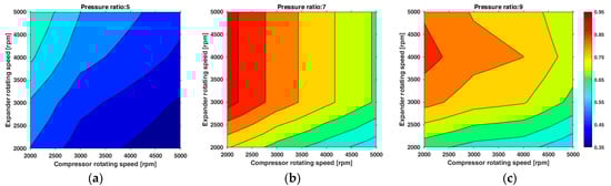
Figure 20.
Maps of the unitary round-trip efficiency of the hypothetic CAES system evaluated for three different pressure ratios: (a) pressure ratio 5, (b) pressure ratio 7, and (c) pressure ratio 9.

Figure 21.
Maps of the power ratio of the hypothetic CAES system evaluated for three different pressure ratios: (a) pressure ratio 5, (b) pressure ratio 7, and (c) pressure ratio 9.
The variations in the inlet air temperature obtained at the same pressure ratio significantly alter the air density, thus directly affecting the theoretical mass flow rate and efficiency exhibited by a volumetric device regardless of its use as an expander or compressor. This concept can be justified by considering that the theoretical mass flow rate processed by a volumetric device is found by multiplying the fluid inlet density by the chamber displacement the number of chambers by the rotating speed and by the cut-off grade.
As a result, this consideration shows that the theoretical mass flow rate is directly proportional to the fluid density at the inlet port. Therefore, this consideration suggests that changes in the inlet air temperature at the same pressure ratio cause the density variation in the air, thus affecting the theoretical air mass flow rate delivered by the volumetric device. In detail, an increase in the air inlet temperature results in a density reduction in the air, thus reducing the theoretical mass flow rate through the device due to the smaller air mass trapped by each operating chamber.
The behavior related to inlet temperature increase is presented in the paper to describe the discharging process in the CAES plant in which the inlet air temperature is higher than the corresponding values measured in the experimental tests, thus causing a slight decrease of around 8% in the air mass flow rate delivered by the expander. Nonetheless, an excessive temperature variation in the air at the same pressure ratio might cause significant density changes that also impact the compression or expansion process. This circumstance may be critical for volumetric devices that work without lubrication oil because this last one cools the working fluid by absorbing heat, thus dampening its temperature variations and the corresponding density changes. For this reason, the operation of a dry-running volumetric expander at the same pressure ratio might be affected by considerable inlet air temperature variations that lead to changes in the air density, thus resulting in under-expansion or over-expansion losses. Such losses are therefore responsible for variations in the isentropic efficiency.
In the present work, the density variation detected at the same pressure ratio from the experimental tests to the CAES discharge process was around 15%, thus considered negligible to affect the trend of the polytropic index that schematizes the expansion process. Therefore, the use of a different inlet temperature in the CAES discharge process was characterized by a reduction in the mass flow rate and the same polytropic expansion index. At the same time, the pressure ratio is another variable whose variations cause changes in the fluid density, thus affecting the mass flow rate through the expander and the expansion process efficiency.
5. Conclusions
This paper presents the results obtained in an experimental process based on compressed air as the working fluid in which a 3 kWe twin-screw compressor was tested as a dry expander to explore its use in small-scale air energy storage without any adjustment and added costs. For this reason, oil injection was employed only in the compressor operation, as oil is indispensable for the correct compression, while it is optional in the expander operation. The machine was tested in a range of rotating speeds between 2000 and 5000 rpm and pressure ratios between 5 and 9. On the one hand, in the compressor operating mode, the absorbed power was in the range of 2.4–3 kWe at the highest rotational speed (5000 rpm), while decreasing to 1–1.5 kWe at the lowest speed (2000 rpm). The overall efficiency of the volumetric machine tested in the design condition was in line with the literature reference, resulting in the range of 57–82%. On the other hand, while working as an expander, the power measured at the shaft was in the range of 0.6–1.6 kWe at 5000 rpm and in the range of 0.3–0.9 kWe at 2000 rpm. The experimental results show a reduction in the efficiency when the machine operated in the expander mode, namely down to a range of 22–39%. This happens because of off-design conditions and the following causes: (i) higher friction losses and internal leaks due to the limited oil quantity injected by the lubricator; (ii) lower flow coefficients of the ports that were responsible for significant pressure losses; and (iii) rotor geometries designed just for the compression process. Despite these disadvantages, the compressor operated as a dry expander, thus being consistent with the literature values for volumetric expanders. Therefore, the availability of these experimental data was profitable to assess the operation of the tested device in a hypothetical micro-CAES that operated under the same pressure ratio as that of the tests with the difference that the stored air was heated up to 80 °C just before the discharge process. The results suggest that the investigated device could lead to a unitary round-trip efficiency between 0.36 and 0.90 and it could recover a discharge power in the range of 12–90% of the power needed for compression.
Author Contributions
Conceptualization, M.F. and M.A.; methodology, A.B. and M.F.; software, M.F.; validation, M.F.; formal analysis, M.F.; investigation, M.F. and M.A.; resources, M.A. and L.S.; data curation, M.F.; writing—original draft preparation, M.F.; writing—review and editing, A.B.; visualization, M.F. and A.B.; supervision, M.A. All authors have read and agreed to the published version of the manuscript.
Funding
This research received no external funding.
Data Availability Statement
The original contributions presented in this study are included in the article. Further inquiries can be directed to the corresponding author(s).
Conflicts of Interest
The authors declare no conflicts of interest.
Appendix A
Appendix A.1. Analysis of the Compressor Operating Mode
The analysis of the compressor operation as an oil-flooded device required that air and oil were considered separately in the calculations because of their immiscibility. The calculation of the polytropic index of the polytropic compression undergone by the air relied on Equation (A1). This relation was found by combining the polytropic transformation formula with the temperature and pressure measurements acquired upstream and downstream of the compressor. In detail, the ratio of discharge pressure to the inlet pressure represented the compression ratio that defined the pressure increase provided by the compressor.
The polytropic index also appears practical to estimate roughly the overall losses in the compressor by introducing an energy balance in which the system included both shafts and their screws. In the experimental conditions, such system is adiabatic and absorbs a mechanical power corresponding to the product of the acquired mechanical torque and the measured rotating speed of the male rotor in since this latter one is connected with the shaft of the bench, as already shown in Equation (1).
As a result, the energy balance of this system states that the sum of the powers and provided by the air and the oil, respectively, to the screws plus the friction power lost in the seals and bearings and plus the absorbed mechanical power is null (Equation (A2), where the terms and are expressed by Equations (A3) and (A4), respectively).
The combination of Equations (A3) and (A4) with Equation (A2) and the use of the fictious polytropic compression to calculate the integral in Equation (A3) lead to the following relation Equation (A5), in which all the dissipative effects due to the turbulence and friction losses in the bearings and seals can be summarized by the term , as shown in Equation (A6).
A source of the dissipation was due to the turbulence caused by the lack of a slide valve, thus implying that the compressor had a fixed built-in volume ratio. As a result, this disadvantage prevents the adjustment of the final pressure to match the conditions downstream after compression, resulting in a final pressure of the air and oil mixture higher than the pressure existing in-line downstream of the compressor. Therefore, the discharge process of the compressor exhibited an instantaneous pressure decrease in the compressed air–oil mixture, whose magnitude also depends on the throttling losses due to the flow of the compressed mixture through the discharge port. This pressure drop leads to an adjustment of the pressure of the air–oil mixture to the in-line pressure conditions and an increase in energy dissipation. Unfortunately, the absence of information about the built-in volume ratio and the measurement of the in-chamber pressure prevented the appreciation of the actual final pressure at the end of the compression and, thus, of the pressure drop. This limitation suggests introducing a quantity named displacement fraction to assess the fraction of the displacement that would be required to reach the same discharge pressure starting from the same initial condition as in a compressor with a slide valve. Although the displacement fraction is not strictly consistent with the actual operation of the compressor because it does not capture the pressure peak at the end of compression, its use is beneficial to distinguish the impact of the compression ratio and rotating speed in the discharge process. The displacement fraction is obtained by considering the polytropic relation written between the initial and final conditions of the compression process as in Equation (A7), with the rewritten terms of the pressure ratio and the polytropic index , as previously shown in Equation (3).
The displacement fraction multiplied by the displacement provides the volume of the operating chamber in which the discharge process should occur during a compression governed by the fictitious polytropic process, thus estimating the amount of displacement to be used progressively to reach the final pressure imposed by the desired compression ratio. Additionally, the experimental data are also practical in determining the heat exchanged between the compressor and the environment. Therefore, this aim required another energy balance (Equation (A8)), with explicit reference to variables that may be measured directly in the experimental setup based on a control volume around the casing in which the inflow and outflow zones matched with the suction and exhaust ports and oil injection port.
The experimental data allow for determining the overall compression efficiency as the ratio of the isentropic power required for an isentropic compression of the air to the mechanical power necessary for the compression of the air–oil mixture under the same compression ratio (Equation (A9)), where the numerator is found by means of Equations (A10) and (A11) and then resulting as shown in Equation (5) in the main text.
The analysis of the volumetric performance in the compressor operating mode is provided by the volumetric efficiency of the compressor, defined as the ratio of the real mass flow rate processed by the device to the theoretical mass flow which such a compressor might process in the same operating conditions as shown in Equation (6). To this end, Utri and Brümmer in [41] suggest that the theoretical mass flow rate of a twin-screw compressor may be calculated by Equation (A12).
Appendix A.2. Analysis of the Expander Operating Mode
Unlike the compressor analysis, the investigation of the expander does not include oil because the expander practically operated as a dry machine. The expansion ratio and the temperatures measured upstream and downstream of the device are the input data requested to calculate the index of the fictitious polytropic process that schematized the expansion process performed in the experiments. Therefore, the index was determined by writing the polytropic formula in terms of the pressure and temperature, thus leading to the following calculation—Equation (A13).
The direct measurements allow finding the mechanical power delivered by the expander by multiplying the measured mechanical torque and the measured rotating speed of the male rotor in , as in the already shown Equation (7). The losses are found by considering the male and female rotors as an adiabatic system, as suggested by the experimental conditions. This energy balance states that the sum of the power provided by the air to the screws in the polytropic expansion (), the power lost in the friction of bearings and seals , and the power provided by the machine is null—Equation (A14). In this relation, the power can be expressed as in the following Equation (A15).
Therefore, the combination of Equations (A13) and (A14) and the use of the fictious polytropic model to calculate the integral in Equation (A15) leads to Equation (A16), whose term represents the power wasted in the frictions of the mechanical parts and in the turbulence—Equation (A17). The calculation of thermal power exchanged between the expander and the environment relies on the energy balance of Equation (A18) that considers the whole device as a control volume in which no leaks through the casing occur, and the inflow and outflow zones matched the inlet and discharge ports.
Furthermore, the measured data allow determining the overall efficiency of the expander as in Equation (A19), in which Equations (A20) and (A21) express the terms in the denominator. Furthermore, the combination of the previous equations leads to the overall efficiency formulation, already shown in the main text as Equation (10), with the influence of the polytropic index and the dissipative effects included in the term .
Differently from the compressor analysis, the assessment of the volumetric performances of the expander required calculating the filling factor [28,56] that compares the measured and the theoretical air mass flow rates, as shown in Equation (A22). The theoretical mass flow rate that the expander can deliver is found as in the compressor analysis (Equation (A12)) multiplied by the cut-off grade of the suction port, as stated in the following Equation (A23). The density of the inlet air in Equation (A24) is inferable from the experimental conditions by considering that the temperature of the compressed air upstream of the expander is comparable to that of the environment, as suggested in an isothermal process. As a result, the inlet air density is obtained from Equation (A24).
The cut-off grade in Equation (A23) depends on the geometry of the expander inlet port and allows assessing the percentage fraction of the displacement dedicated to the filling process of each working chamber. Moreover, the reversible usage of the device has the consequence that the expander inlet port corresponds to the compressor discharge port, whose design has to ensure sufficient timing to ensure a complete discharge process of the compressed gas with the lowest pressure losses. Unfortunately, the unavailability of the design parameters of the device entailed some difficulties in the evaluation of an accurate value of the expander cut-off grade. However, an appraisal of the cut-off grade appeared still possible because of the following assumptions: (i) the expander operated as a compressor in which the fluid flows in the reverse direction and occurs from the compressor discharge port to the inlet port; and (ii) the actual expansion process can be represented by means of a fictitious polytropic process.
Therefore, these assumptions suggest that the cut-off grade in the expander operation practically matches the displacement factor of the compressor because the volume swept by the screws that is intercepted by the compressor discharge port has the same value in both operating modes. Although this approach does not allow an exact calculation of the actual value of the cut-off grade, it still permitted a reasonable estimation to compare the results gathered during the compression and expansion operations. As a result, these considerations allow rewriting the previous Equation (A23) as the following relation (Equation (A25)). Therefore, the filling factor becomes like in Equation (A26).
Appendix B
Micro-CAES Key Perfomance Indicators’ Calculations
The heating process occurring in the discharge process in a CAES layout leads to a higher temperature of the air in the storage than the corresponding experimental value, thus causing mass flow rates through the expander that differed from those of the experiments. As a result, the new mass flow rate that would occur through the expander under the same expansion ratio and a different upstream air temperature can be found by considering the expander as a nozzle working under a fixed pressure ratio and given upstream pressure and temperature. In this situation, the mass flow rate through the nozzle is directly proportional by a constant term to the ratio of the pressure to the square root of the upstream temperature, as shown in the relation Equation (A27). Therefore, Equation (A27) and the experimental data allowed calculating as in Equation (A28). Finally, the knowledge of the constant term allowed finding, by Equation (A29), the mass flow rate that would be delivered by the expander when the air in the storage is at a pressure , as in the tests but with a different temperature . The discharge process that occurs from the storage temperature under the expansion ratio entails an isentropic enthalpy drop of the air expressed by Equation (A30).
Although the air temperature in the storage differs from the experiments, the isentropic efficiency of the expander in the discharge process may be considered the same as in the tests. The reason is that the isentropic efficiency mainly in a volumetric device mainly depends on the pressure ratio [24], whose value is the same for the hypothetical CAES under investigation and the experiments. As a result, the mechanical power that the expander would deliver in the discharge process is calculated by Equation (A31), corresponding to an expansion work per unit of mass expressed by Equation (A32). At the same time, the compression work and the heat per unit of mass are obtained from Equations (A33) and (A34), respectively, in which the compression work per unit is calculated by considering that the compressor processes both air and oil. The quantities , , and allow defining a unitary round-trip efficiency (Equation (12)) that exclusively assesses the behavior of the tested twin-screw machine in this hypothetical CAES system without considering the filling and emptying process of the reservoir. The filling and emptying processes depend on reservoir dimensions that determine the storable air mass under specific thermodynamic conditions. For this reason, the use of quantities defined per unit of mass in the unitary round-trip efficiency avoids the need to model the storage behavior and allows estimating the losses that occur from the recovery of energy during the compression up to the following conversion into useful energy based the heating and expansion processes. Another parameter that depicts the operation of the same device in such a CAES system is the expander to compressor power ratio indicated as PR (Equation (13)), comparing the delivered power in the discharge with the power requested in the charge process.
References
- Leszczyński, J.S.; Gryboś, D.; Markowski, J. Analysis of optimal expansion dynamics in a reciprocating drive for a micro-CAES production system. Appl. Energy 2023, 350, 121742. [Google Scholar] [CrossRef]
- Sun, J.; Peng, B.; Zhu, B.; Li, Y. Research on the performance characteristics of an oil-free scroll expander that is applied to a micro-scale compressed air energy storage system. J. Energy Storage 2023, 63, 106896. [Google Scholar] [CrossRef]
- Quoilin, S.; Van Den Broek, M.; Declaye, S.; Dewallef, P.; Lemort, V. Techno-economic survey of organic rankine cycle (ORC) systems. Renew. Sustain. Energy Rev. 2013, 22, 168–186. [Google Scholar] [CrossRef]
- Olabi, G.; Wilberforce, T.; Ramadan, M.; Ali, M.; Hai, A. Compressed air energy storage systems: Components and operating parameters—A review. J. Energy Storage 2021, 34, 102000. [Google Scholar] [CrossRef]
- Liu, Z.; Li, Z.; Xie, D.; Wu, H. Unsteady characteristic and flow mechanism of a scroll compressor in small-scale compressed air energy storage system. J. Energy Storage 2022, 51, 104368. [Google Scholar] [CrossRef]
- Chen, S.; Arabkoohsar, A.; Zhu, T.; Pagh, M. Development of a micro-compressed air energy storage system model based on experiments. Energy 2020, 197, 117152. [Google Scholar] [CrossRef]
- Wang, Y.; Wang, Z.; Li, M.; Chen, T.; Wang, Z. An optimal matching strategy for screw compressor for heat pump applications. Appl. Therm. Eng. 2018, 132, 333–340. [Google Scholar] [CrossRef]
- Imran, M.; Usman, M.; Park, B.S.; Lee, D.H. Volumetric expanders for low grade heat and waste heat recovery applications. Renew. Sustain. Energy Rev. 2016, 57, 1090–1109. [Google Scholar] [CrossRef]
- Kovacevic, N.S.K.S. Screw Compressors Mathematical Modelling and Performance Calculation; Springer: Berlin/Heidelberg, Germany, 2005. [Google Scholar]
- Singh, P.; Bowman, J. Heat Transfer in Oil-Flooded Screw Compressors. In Proceedings of the International Compressor Engineering Conference; 1986; pp. 135–153. Available online: https://docs.lib.purdue.edu/icec/521 (accessed on 8 January 2025).
- Basha, N.; Kovacevic, A.; Stosic, N.; Smith, I. Effect of oil-injection on twin screw compressor performance. IOP Conf. Ser. Mater. Sci. Eng. 2018, 425, 012009. [Google Scholar] [CrossRef]
- Wu, X.; Xing, Z.; He, Z.; Wang, X.; Chen, W. Effects of lubricating oil on the performance of a semi-hermetic twin screw refrigeration compressor. Appl. Therm. Eng. 2017, 112, 340–351. [Google Scholar] [CrossRef]
- Li, J.; Wu, H.; Wang, B.; Xing, Z.; Shu, P. Research on the performance of water-injection twin screw compressor. Appl. Therm. Eng. 2009, 29, 3401–3408. [Google Scholar] [CrossRef]
- Wang, C.; Xing, Z.; Chen, W.; Sun, S.; He, Z. Analysis of the leakage in a water-lubricated twin-screw air compressor. Appl. Therm. Eng. 2019, 155, 217–225. [Google Scholar] [CrossRef]
- Shen, J.; Xing, Z.; Zhang, K.; He, Z.; Wang, X. Development of a water-injected twin-screw compressor for mechanical vapor compression desalination systems. Appl. Therm. Eng. 2016, 95, 125–135. [Google Scholar] [CrossRef]
- Shen, J.; Xing, Z.; Wang, X.; He, Z. Analysis of a single-effect mechanical vapor compression desalination system using water injected twin screw compressors. Desalination 2014, 333, 146–153. [Google Scholar] [CrossRef]
- Wu, H.; Lin, K.; Huang, H.; Xiong, B.; Zhang, B.; Xing, Z. Research on Effects of Vapor Injection on Twin-screw Compressor Performance. Int. J. Refrig. 2020, 118, 483–490. [Google Scholar] [CrossRef]
- Guerrato, D.; Nouri, J.M.; Stosic, N.; Arcoumanis, C.; Smith, I.K. Flow measurements in the discharge port of a screw compressor. Proc. Inst. Mech. Eng. Part E J. Process Mech. Eng. 2008, 222, 201–210. [Google Scholar] [CrossRef]
- Guerrato, D.; Nouri, J.M.; Stosic, N.; Arcoumanis, C. Flow and pressure characteristics within a screw compressor. J. Phys. Conf. Ser. 2007, 85, 012012. [Google Scholar] [CrossRef]
- Read, M.; Smith, I.; Stosic, N. Port Flow Losses in Internally Geared Positive Displacement Machines. In Proceedings of the 24th International Compressor Engineering Conference at Purdue, West Lafayette, IN, USA, 9–12 July 2018; pp. 1–9. [Google Scholar]
- Tian, Y.; Lu, J.; Shen, J.; Wu, H.; Xing, Z. Optimization on shaft seals for a twin-screw steam compressor based on a novel uniform property region (UPR) model on discharge end-face. Int. J. Refrig. 2018, 91, 167–176. [Google Scholar] [CrossRef]
- Leibowitz, H.; Smith, I.K.; Stosic, N. Cost effective small scale ORC systems for power recovery from low grade heat sources. In Proceedings of the ASME 2006 International Mechanic Engineering Congress and Exposition, Chicago, IL, USA, 5–10 November 2006. [Google Scholar]
- Qiu, G.; Liu, H.; Riffat, S. Expanders for micro-CHP systems with organic Rankine cycle. Appl. Therm. Eng. 2011, 31, 3301–3307. [Google Scholar] [CrossRef]
- Antonelli, M.; Baccioli, A.; Francesconi, M.; Martorano, L. Numerical and experimental analysis of the intake and exhaust valves of a rotary expansion device for micro generation. Energy Procedia 2015, 81, 461–471. [Google Scholar] [CrossRef]
- Rahbar, K.; Mahmoud, S.; Al-Dadah, R.K.; Moazami, N.; Mirhadizadeh, S.A. Review of organic Rankine cycle for small-scale applications. Energy Convers. Manag. 2017, 134, 135–155. [Google Scholar] [CrossRef]
- Tang, H.; Wu, H.; Wang, X.; Xing, Z. Performance study of a twin-screw expander used in a geothermal organic Rankine cycle power generator. Energy 2015, 90, 631–642. [Google Scholar] [CrossRef]
- Wang, C.; Xing, Z.; Sun, S.; Chen, W.; He, Z. Experimental study on the performance of oil-free twin-screw expanders for recovering energy in fuel cell systems. Appl. Therm. Eng. 2020, 165, 114613. [Google Scholar] [CrossRef]
- Wang, C.; Xing, Z.; Sun, S.; He, Z. Loss analysis of oil-free twin-screw expanders for recovering energy in fuel cell systems by means of p-θ diagrams. Energy 2020, 201, 117581. [Google Scholar] [CrossRef]
- Tian, Y.; Xing, Z.; He, Z.; Wu, H. Modeling and performance analysis of twin-screw steam expander under fluctuating operating conditions in steam pipeline pressure energy recovery applications. Energy 2017, 141, 692–701. [Google Scholar] [CrossRef]
- Yao, S.; Zhang, Y.; Deng, N.; Yu, X.; Dong, S. Performance research on a power generation system using twin-screw expanders for energy recovery at natural gas pressure reduction stations under off-design conditions. Appl. Energy 2019, 236, 1218–1230. [Google Scholar] [CrossRef]
- Bianchi, G.; Kennedy, S.; Zaher, O.; Tassou, S.A.; Miller, J.; Jouhara, H. Numerical modeling of a two-phase twin-screw expander for Trilateral Flash Cycle applications. Int. J. Refrig. 2018, 88, 248–259. [Google Scholar] [CrossRef]
- Nikolov, A.; Brümmer, A. Two-phase mass flow rate through restrictions in liquid-flooded twin-screw compressors or expanders. Int. J. Refrig. 2023, 148, 152–167. [Google Scholar] [CrossRef]
- Wang, C.; Liu, M.; Li, Z.; Xing, Z.; Shu, Y. Performance improvement of twin-screw air expander used in PEMFC systems by two-phase expansion. Energy 2023, 273, 127249. [Google Scholar] [CrossRef]
- Francesconi, M.; Briola, S.; Antonelli, M. A Review on Two-Phase Volumetric Expanders and Their Applications. Appl. Sci. 2022, 12, 10328. [Google Scholar] [CrossRef]
- Daniarta, P.; Kolasìnski, S.; Imre, A.R. A Preliminary Design and Modeling Analysis of Two-Phase Volumetric Expanders for a Novel Reversible Organic Rankine-Based Cycle for Carnot Battery Technology. Appl. Sci. 2022, 12, 3557. [Google Scholar] [CrossRef]
- Steger, D.; Feist, M.; Schlücker, E. Using a screw-type machine as reversible compressor–expander in a Carnot Battery: An analytical study towards efficiency. Appl. Energy 2022, 316, 118950. [Google Scholar] [CrossRef]
- Eppinger, B.; Steger, D.; Regensburger, C.; Karl, J.; Schlücker, E.; Will, S. Carnot battery: Simulation and design of a reversible heat pump-organic Rankine cycle pilot plant. Appl. Energy 2021, 288, 116650. [Google Scholar] [CrossRef]
- He, Y.; Xing, L.; Zhang, Y.; Zhang, J.; Cao, F.; Xing, Z. Development and experimental investigation of an oil-free twin-screw air compressor for fuel cell systems. Appl. Therm. Eng. 2018, 145, 755–762. [Google Scholar] [CrossRef]
- Abdan, S.; Stosic, N.; Kovacevic, A.; Smith, I.; Asati, N. Oil drag loss in oil-flooded, twin-screw compressors. Proc. Inst. Mech. Eng. Part E J. Process Mech. Eng. 2023, 237, 1137–1144. [Google Scholar] [CrossRef]
- Wang, C.; Xing, Z.; Chen, W.; Yang, Q.; He, Z. Development of an oil free water-lubricated twin-screw air compressor. Appl. Therm. Eng. 2018, 143, 396–402. [Google Scholar] [CrossRef]
- Utri, M.; Brümmer, A. Improvement of the Efficiency of Twin-Screw Refrigeration Compressors by means of Dual Lead Rotors. In Proceedings of the 23rd International Compressor Engineering Conference at Purdue, West Lafayette, IN, USA, 11–14 July 2016; pp. 1–10. [Google Scholar]
- Basha, N.; Kovacevic, A.; Rane, S. Analysis of oil-injected twin-screw compressor with multiphase flow models. Designs 2019, 3, 54. [Google Scholar] [CrossRef]
- He, Z.; Wang, T.; Wang, X.; Peng, X.; Xing, Z. Experimental investigation into the effect of oil injection on the performance of a variable speed twin-screw compressor. Energies 2018, 11, 1342. [Google Scholar] [CrossRef]
- Dhayanandh, K.K.; Rameshkumar, K.; Sumesh, A.; Lakshmanan, N. Influence of oil injection parameters on the performance of diesel powered screw air compressor for water well application. Meas. J. Int. Meas. Confed. 2020, 152, 107323. [Google Scholar] [CrossRef]
- Abdan, S.; Stosic, N.; Kovacevic, A.; Smith, I.; Deore, P. Identification and analysis of screw compressor mechanical losses. IOP Conf. Ser. Mater. Sci. Eng. 2018, 425, 012015. [Google Scholar] [CrossRef]
- Francesconi, M.; Antonelli, M. A numerical model for the prediction of the fluid dynamic and mechanical losses of a Wankel-type expansion device. Appl. Energy 2017, 205, 225–235. [Google Scholar] [CrossRef]
- Francesconi, M.; Caposciutti, G.; Antonelli, M. An experimental and numerical analysis of the performances of a Wankel steam expander. Energy 2018, 164, 615–626. [Google Scholar] [CrossRef]
- Wang, B.; Wu, X.; Wang, C.; Zhang, Z.; Li, Y.; Xing, Z. Performance improvement of twin screw refrigeration compressors for chillers by modifying the suction arrangement. Int. J. Refrig. 2024, 158, 100–110. [Google Scholar] [CrossRef]
- Fujiwara, M.; Osada, Y. Performance analysis of an oil-injected screw compressor and its application. Int. J. Refrig. 1995, 18, 220–227. [Google Scholar] [CrossRef]
- Ma, Y.; Zhou, Y.; Zhu, Z. The Investigation of Two-Phase Expansion Performance with Indicator Diagram in a Twin-Screw Expander. Processes 2023, 11, 1862. [Google Scholar] [CrossRef]
- Lin, S. A CFD-based study of twin-screw expander performance and inlet structure optimization. J. Phys. Conf. Ser. 2023, 2441, 012069. [Google Scholar] [CrossRef]
- Yao, S.; Zhang, Y.; Yang, H. Performance Research on a Twin Screw Expander Applied to a Power Generation System for Recovering Waste Pressure Energy of Natural Gas. J. Phys. Conf. Ser. 2018, 1072, 012016. [Google Scholar] [CrossRef]
- Eyerer, S.; Dawo, F.; Rieger, F.; Schuster, A.; Aumann, R.; Wieland, C.; Spliethoff, H. Experimental and numerical investigation of direct liquid injection into an ORC twin-screw expander. Energy 2019, 178, 867–878. [Google Scholar] [CrossRef]
- Hu, F.; Zhang, Z.; Chen, W.; He, Z.; Wang, X.; Xing, Z. Experimental Investigation on the Performance of a Twin-screw Expander Used in an ORC System. Energy Procedia 2017, 110, 210–215. [Google Scholar] [CrossRef]
- Nikolov, A.; Brümmer, A. Investigating a small oil-flooded twin-screw expander for waste-heat utilisation in organic rankine cycle systems. Energies 2017, 10, 869. [Google Scholar] [CrossRef]
- Papes, I.; Degroote, J.; Vierendeels, J. New insights in twin screw expander performance for small scale ORC systems from 3D CFD analysis. Appl. Therm. Eng. 2015, 91, 535–546. [Google Scholar] [CrossRef]
- Dumont, O.; Dickes, R.; Lemort, V. Experimental investigation of four volumetric expanders Experimental investigation of four volumetric expanders. Energy Procedia 2017, 129, 859–866. [Google Scholar] [CrossRef]
- Fatigati, F.; Di Bartolomeo, M.; Di Battista, D.; Cipollone, R. A dual-intake-port technology as a design option for a Sliding Vane Rotary Expander of small-scale ORC-based power units. Energy Convers. Manag. 2020, 209, 112646. [Google Scholar] [CrossRef]
- Guo, Z.; Zhang, C.; Wu, Y.; Lei, B.; Yan, D.; Zhi, R.; Shen, L. Numerical optimization of intake and exhaust structure and experimental verification on single-screw expander for small-scale ORC applications. Energy 2020, 199, 117478. [Google Scholar] [CrossRef]
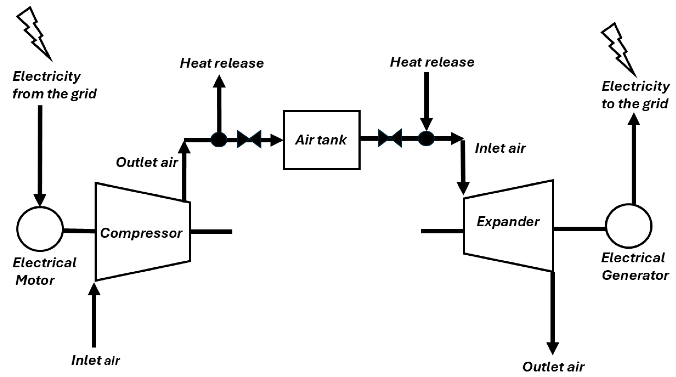
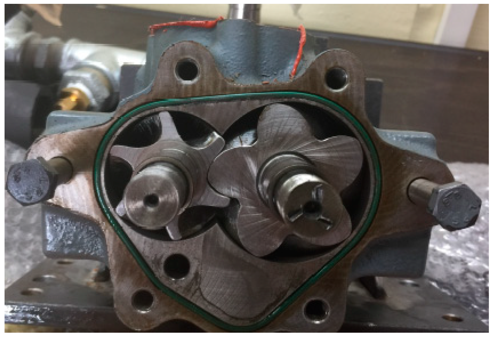
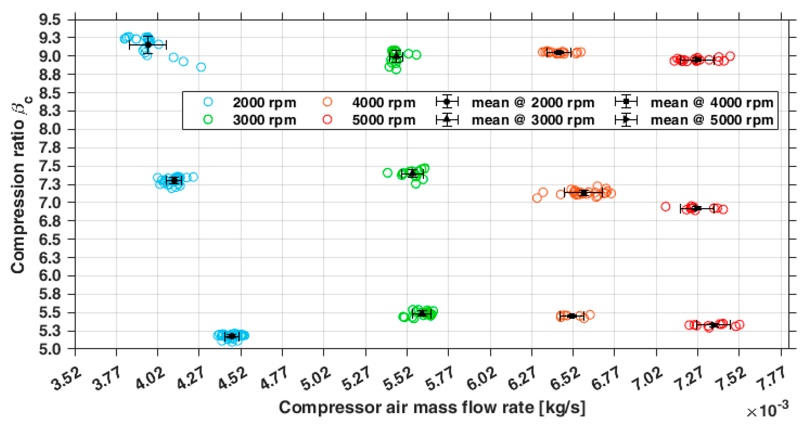
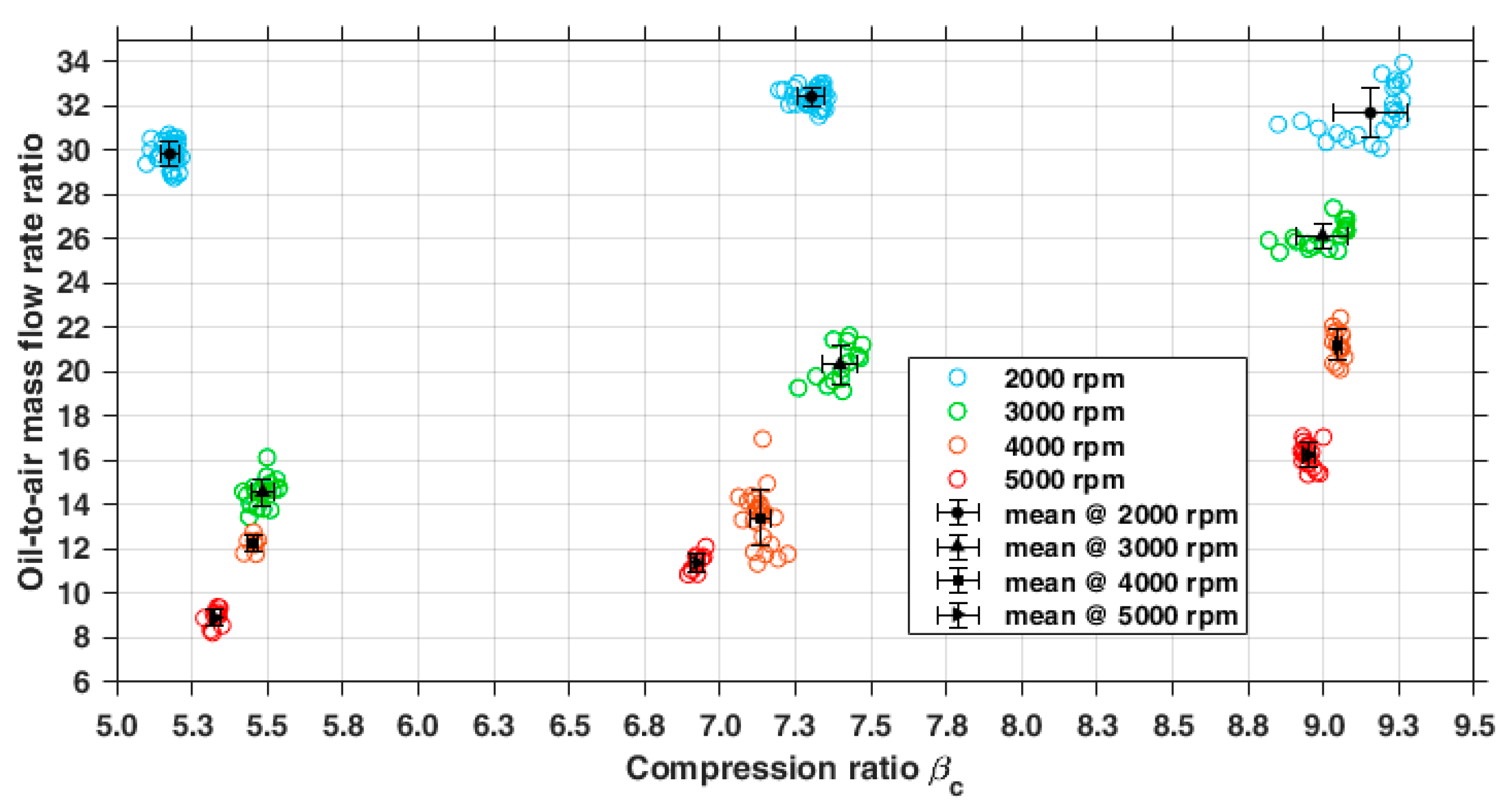
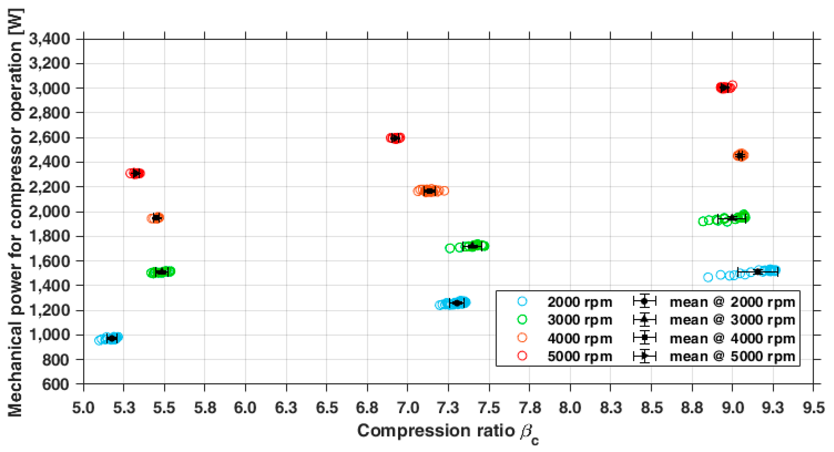
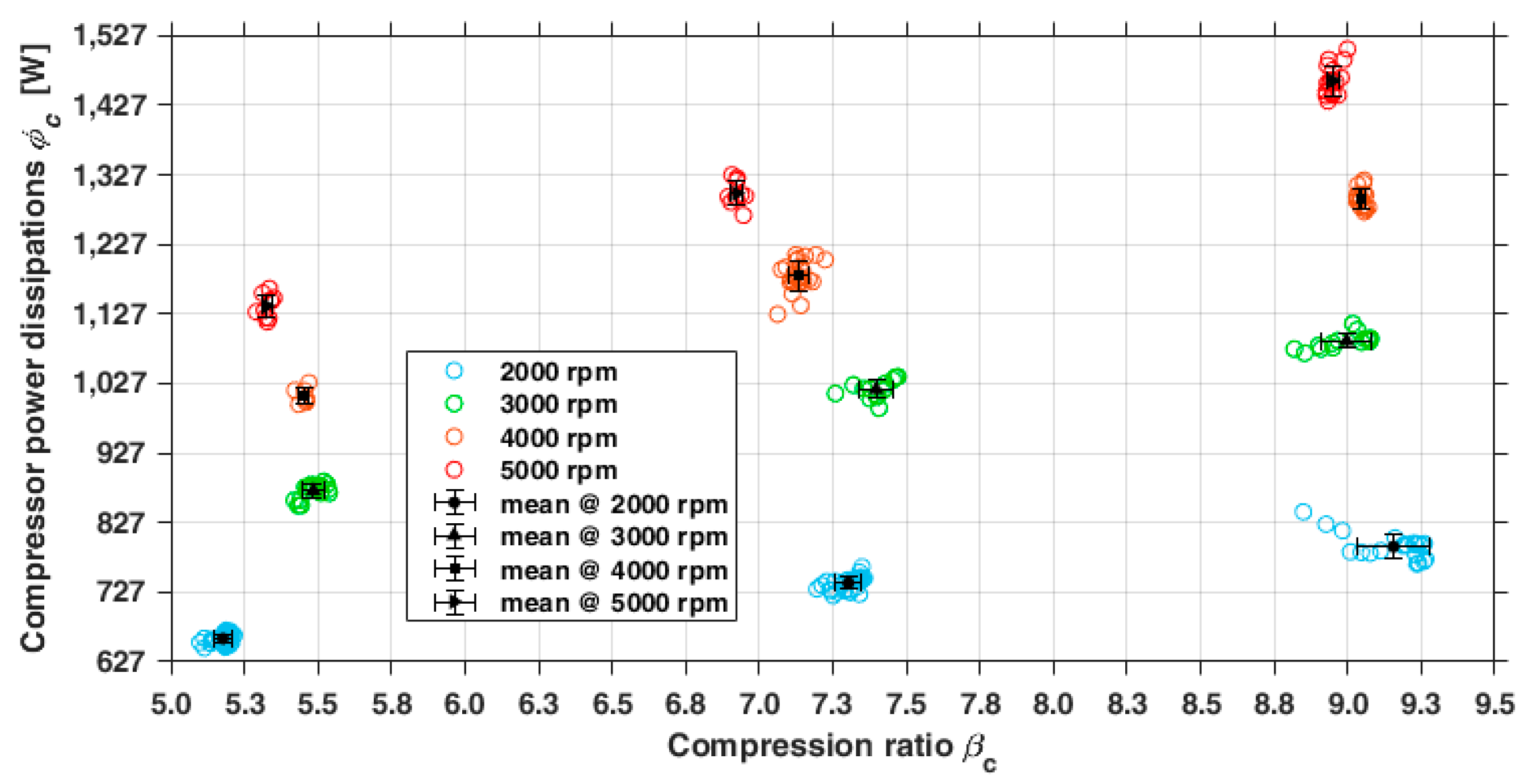
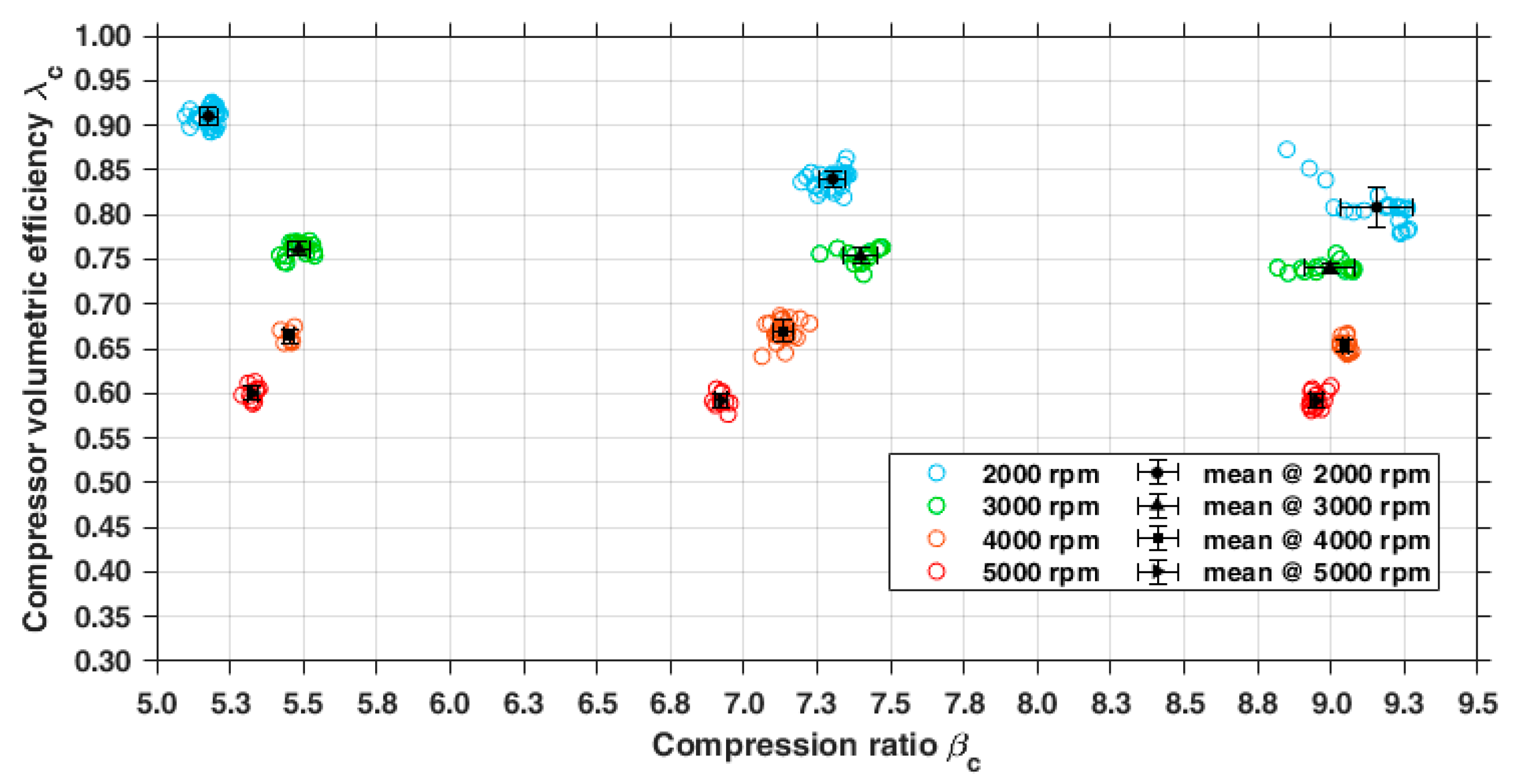
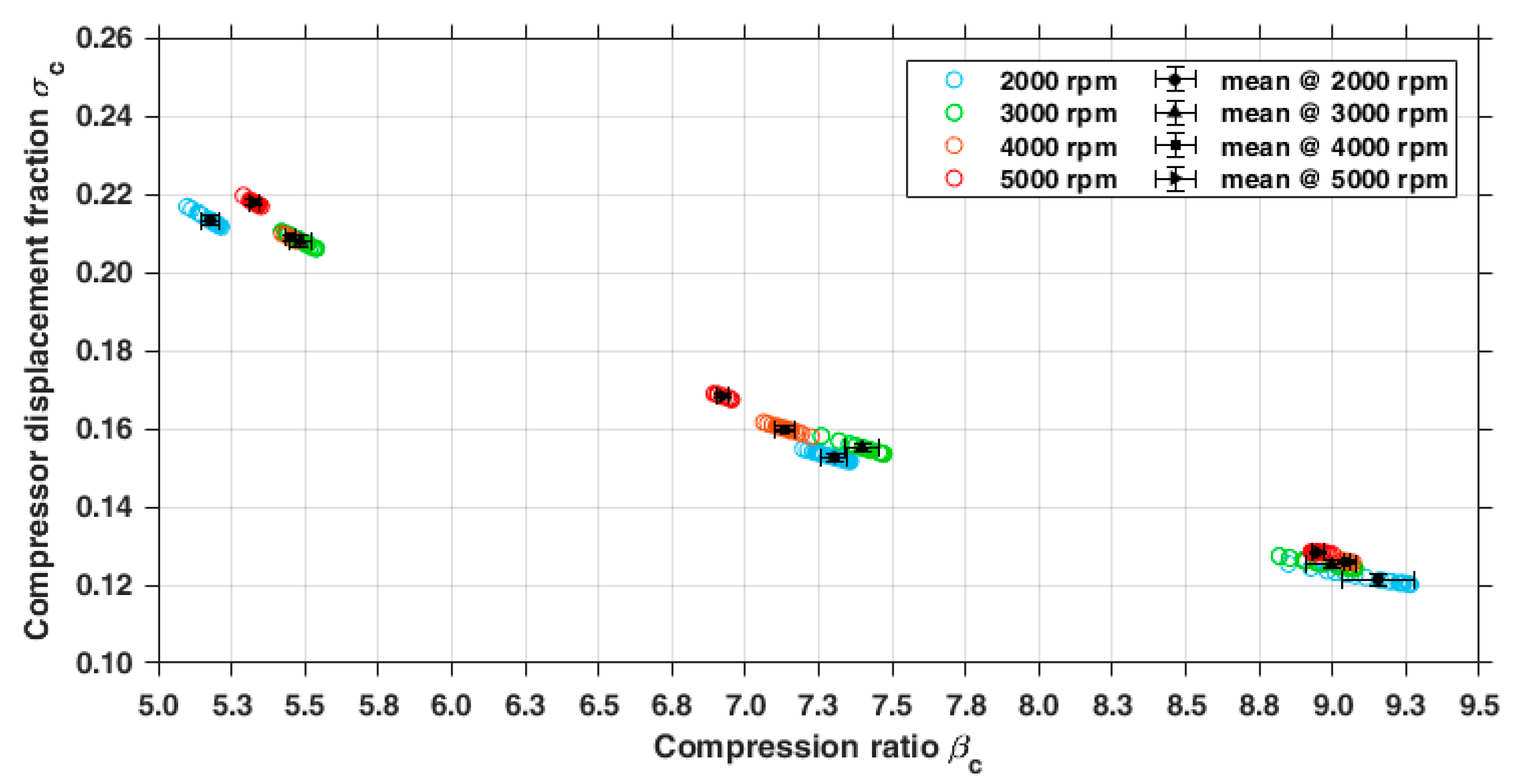
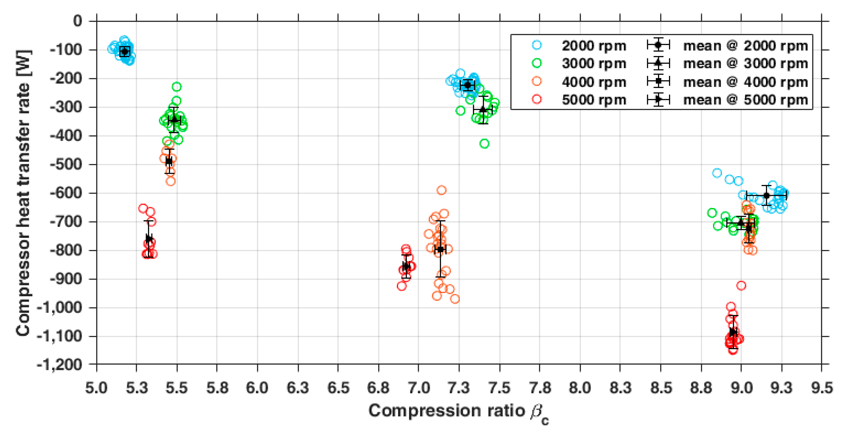
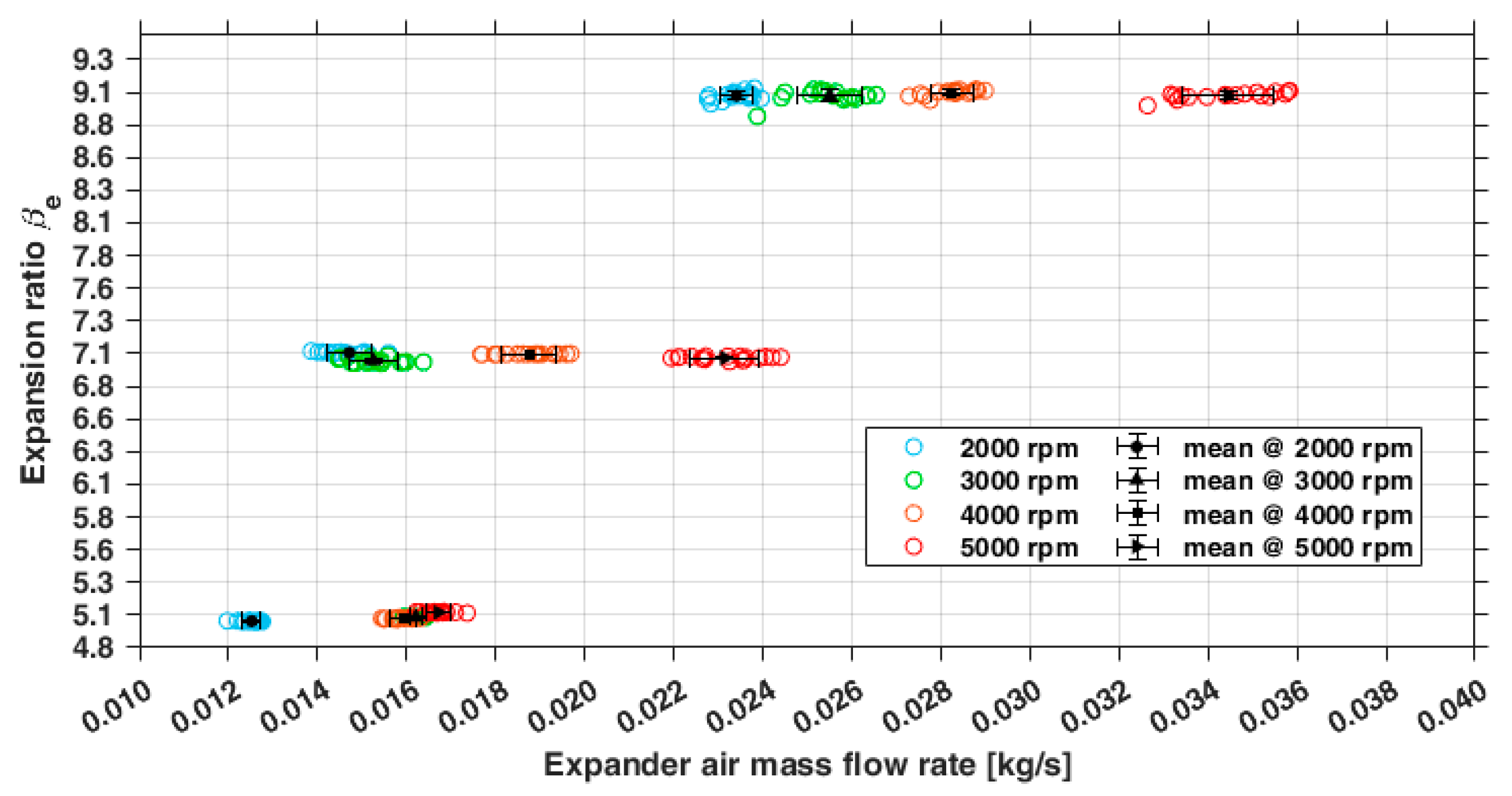
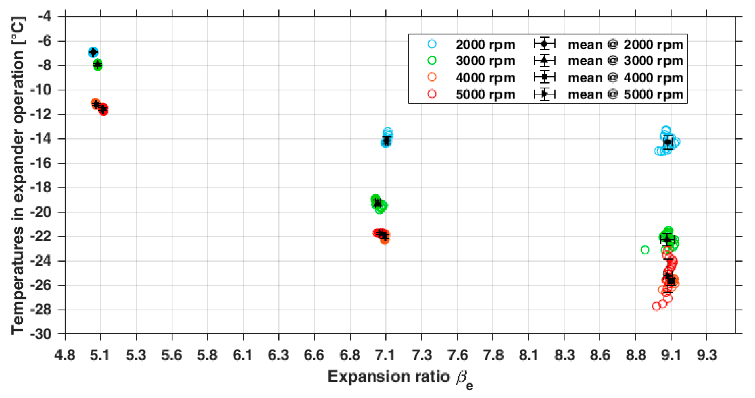
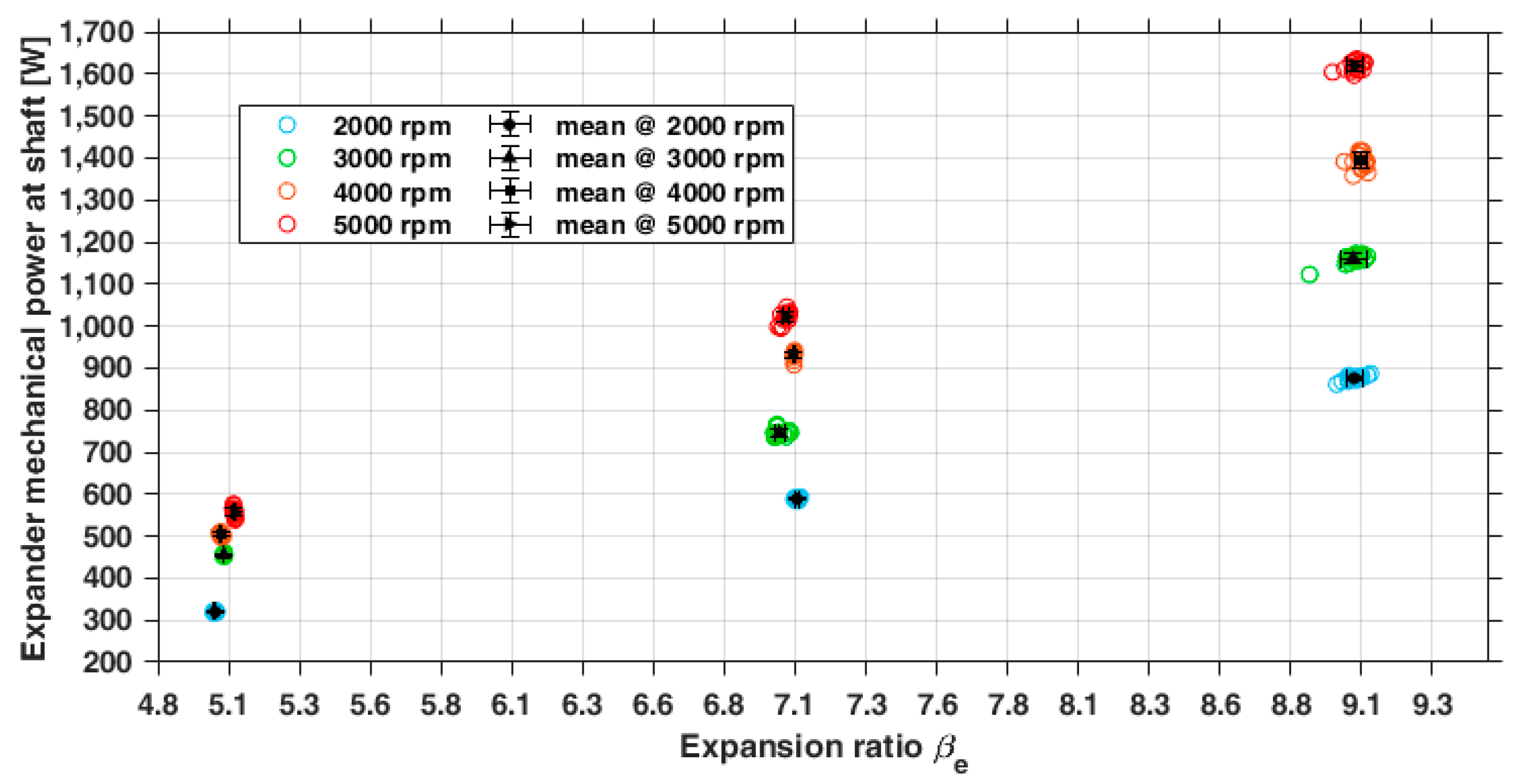
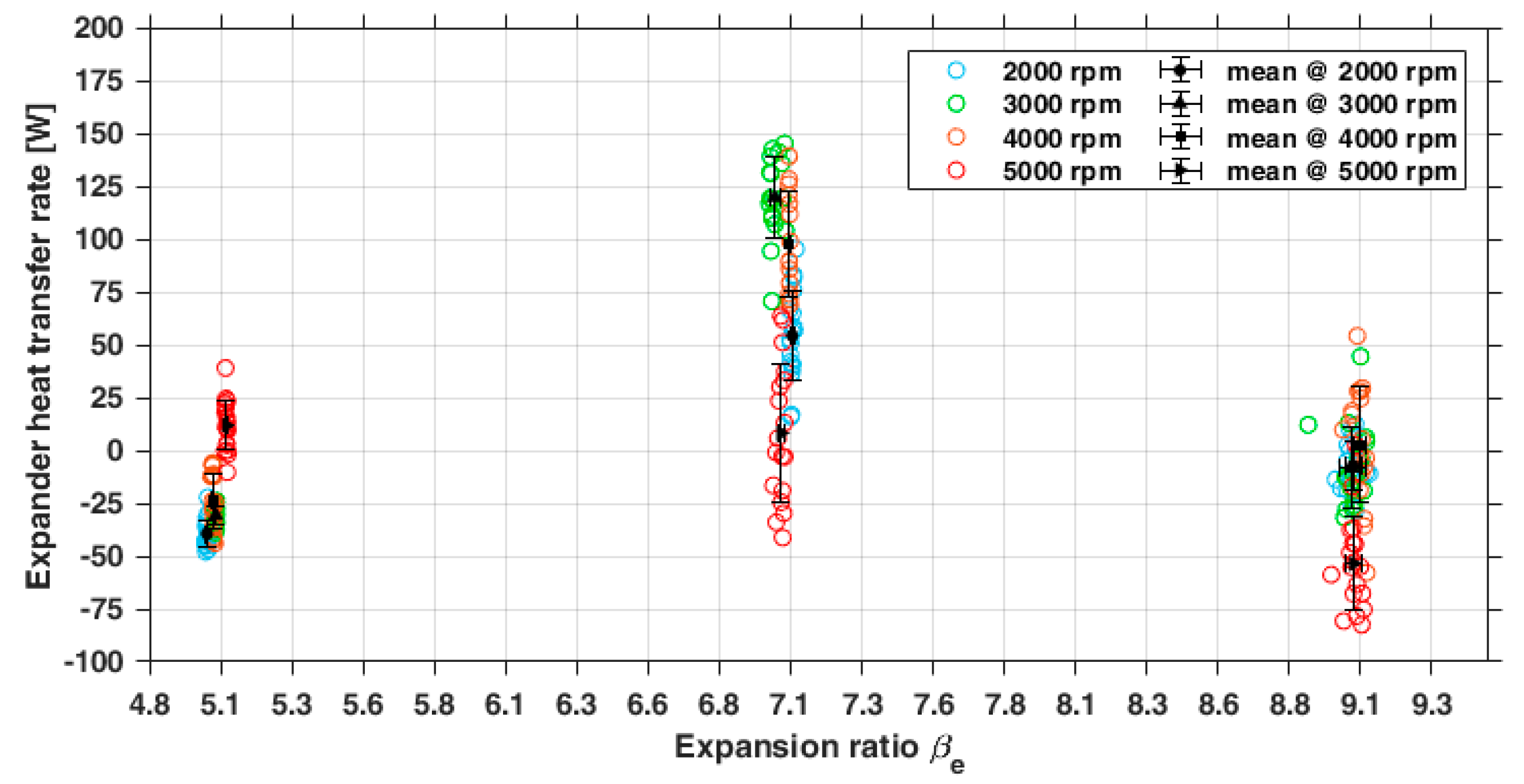
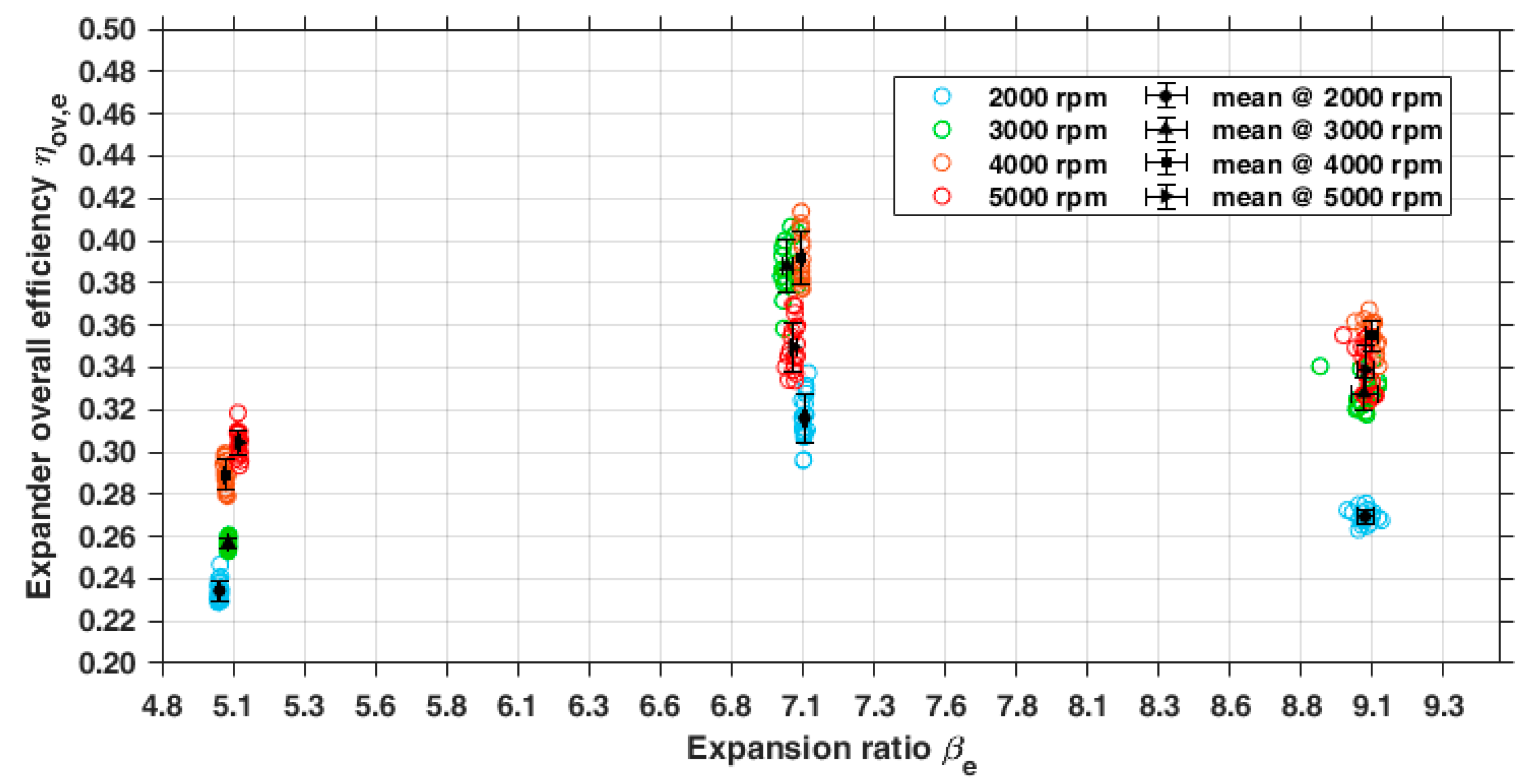
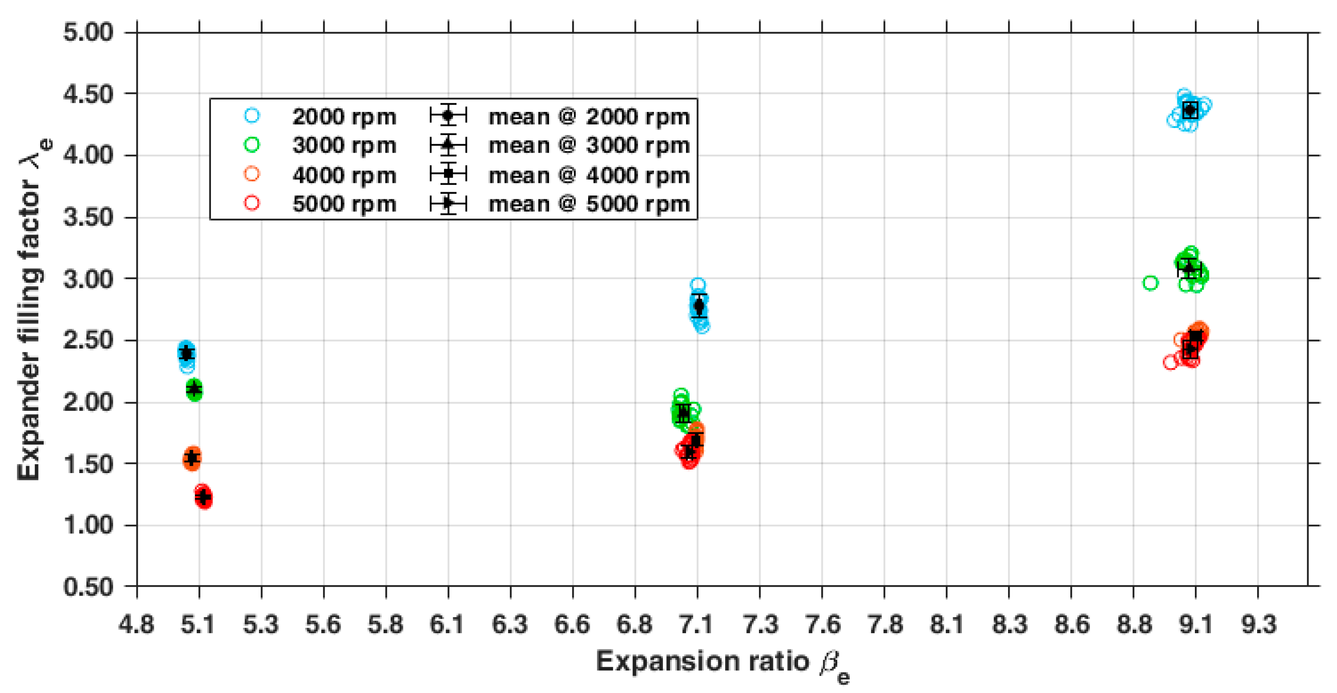

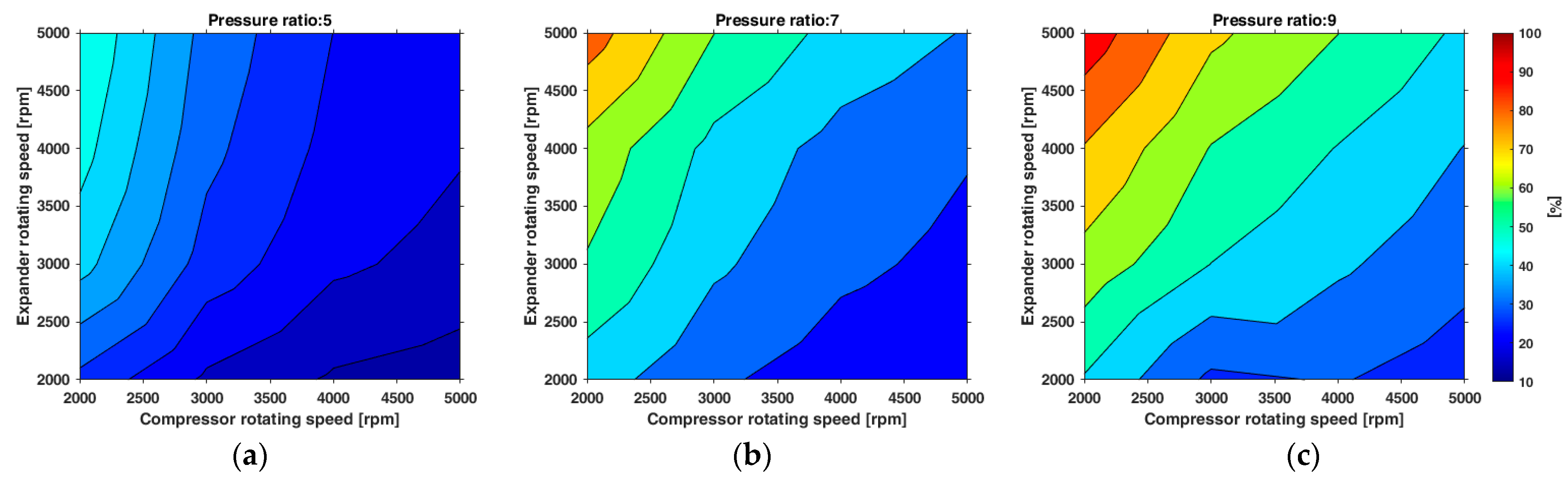
Disclaimer/Publisher’s Note: The statements, opinions and data contained in all publications are solely those of the individual author(s) and contributor(s) and not of MDPI and/or the editor(s). MDPI and/or the editor(s) disclaim responsibility for any injury to people or property resulting from any ideas, methods, instructions or products referred to in the content. |
© 2025 by the authors. Licensee MDPI, Basel, Switzerland. This article is an open access article distributed under the terms and conditions of the Creative Commons Attribution (CC BY) license (https://creativecommons.org/licenses/by/4.0/).