Article

Optimization of Development Strategies and Injection-Production Parameters in a Fractured-Vuggy Carbonate Reservoir by Considering the Effect of Karst Patterns: Taking C Oilfield in the Tarim Basin as an Example

1
Tarim Oilfield Company, PetroChina, Korla 841000, China
2
R&D Center for Ultra-Deep Complex Reservoir Exploration and Development, CNPC, Korla 841000, China
3
Engineering Research Center for Ultra-Deep Complex Reservoir Exploration and Development, CNPC, Korla 841000, China
4
Research Institute of Petroleum Exploration and Development, PetroChina, Beijing 100083, China
*
Author to whom correspondence should be addressed.
These authors contributed equally to this work.
Energies 2025, 18(2), 319; https://doi.org/10.3390/en18020319
Submission received: 31 October 2024 / Revised: 29 November 2024 / Accepted: 13 December 2024 / Published: 13 January 2025
(This article belongs to the Section H: Geo-Energy)

Abstract

:
The spatial structural characteristics of fractured-vuggy units vary greatly in different karst patterns, which significantly influence the study of remaining oil distribution patterns in ultra-deep fractured-vuggy reservoirs and the determination of the most efficient development strategies. However, few numerical simulation studies have focused on improving water and gas injection in fractured-vuggy reservoirs by considering the effect of karst patterns. By taking a typical fractured-vuggy reservoir in C oilfield in Tarim Basin, China as an example, the development dynamic characteristics of eight typical fractured-vuggy units in three different karst patterns are analyzed, and based on the newly proposed numerical simulation method of fluid vertical equilibrium, the residual oil reservoir distribution in different karst pattern fractured-vuggy units are studied, and the effects of fracture-vuggy karst patterns on the development characteristics, on the remaining oil morphology pattern, on the development strategies, and on the injection-production parameters are explored. This study shows that for different karst patterns fractured-vuggy units, the complexity of spatial structure, reserve scale, and oil-water relationship aggravates the heterogeneity of reservoirs and results in substantial differences in the development of dynamic patterns. In the northern facing karst fractured-vuggy units, there are two main types of remaining oil: well-spacing type and local-blocking type, and the reasonable development strategies are affected by reservoir morphology and the connectivity of structure patterns. Attic-type remaining oil mainly occurs in platform margin overlay and fault-controlled karst fractured-vuggy units. In the southern fault-controlled karst area, the remaining oil is mostly found along the upper part, and periodic gas injection or N2 huff-n-puff is recommended with priority for potential tapping. The fractured-vuggy karst patterns show a significant influence on the optimal level of injection-production parameters for improving the development of gas injection development strategies. The ideas of improving water injection and gas injection for fracture-vuggy reservoirs proposed in this paper also provide a good reference to further improve water control and increase oil production in other similar carbonate reservoirs.

1. Introduction

Marine carbonate reservoirs are widely distributed in the United States, the Middle East, and Central Asia, accounting for 52% of the world’s proven recoverable reserves and 60% of the world’s production, occupying a large proportion of global oil and gas resources [1,2,3,4]. Marine carbonate rocks are transformed and overlayed by multi-type, multi-stage diagenesis and tectonism mechanisms in geological processes [5], forming various types of pores, vugs, and fracture systems [6]. Based on reservoir space, carbonate reservoirs can be divided into porous type, fracture-porous type, and karst fractured-vuggy type [7]. Karst fractured-vuggy carbonate reservoirs are widespread in China, mainly in the Tarim Basin and Bohai Bay Basin, and have played an important role in increasing oil reserves and production in recent years [8,9]. The karstification process improves porosity and permeability of the reservoir, which is mainly affected by the karstification stage, karst fractured-vuggy pattern, and the differences in controlling factors. Fractured-vuggy units with different fracture distribution characteristics widely exist in each karst area [10,11,12,13,14,15,16]. Karst fractured-vuggy reservoirs are generally characterized by strong heterogeneity, multiple reservoir types, poor connectivity, complex flow mechanisms, and diverse oil-water relationships [13,17,18,19,20]. Refined analysis of typical fractured-vuggy units by considering the effect of karst structures is very important to determine the reasonable development strategy of water or gas injection.
Elastic energy or natural bottom water is mainly used to exploit the karst fractured-vuggy carbonate reservoirs in the early stages, and water or gas injection is carried out to supplement the formation voidage after a significant decrease in reservoir pressure [20,21,22,23,24,25,26]. Due to a poor understanding of reservoir geology and dynamic characteristics, few optimal designs of injection-production parameters typically result in a significant difference in actual production performance when water or gas injection is executed in pilot [27,28]. In order to improve the oil recovery degree, great efforts have been made through physical experiments and numerical simulation. Several physical models for typical fractured-vuggy units were designed to conduct water flooding experiments [14,27,28,29]. The results showed that oil-water density, fractured-vuggy connectivity, oil-water viscosity ratio, filling degree, water injection rate, and injection mode all exerted an impact on the actual performance of water flooding and remaining oil distribution. Hou et al. [30] compared the differences between continuous and intermittent water injection using three-dimensional physical experiments and found that fractured-vuggy connectivity, well depth, and injection-production relationship greatly affected the production performance. Influenced by gravity and viscosity resistance, the producers drilled at fractures and vugs show completely different dynamic characteristics. By considering reservoir geological distribution, Lyu et al. [31] designed a physical simulation model of a fractured-vuggy carbonate reservoir and carried out water flooding and N2 flooding experiments. The remaining oil after water flooding are mainly divided into two categories—one that occupies at the top of vugs and the other that remains unexploited due to the delay in high-permeability channels during water flooding. It can be concluded from N2 flooding experiments that the major enhanced oil recovery (EOR) mechanisms of gas flooding in karst fractured-vuggy carbonate reservoirs involves creating a secondary gas cap to displace the remaining oil, changing the distribution of the original pressure field to exploit the remaining oil blocked through high permeability channels, and supplementing formation energy. The displacement efficiency is fully influenced by geological conditions (e.g., the presence of remaining oil around injectors, degree of filling, and well-storage configuration), bottom water energy, injection opportunity, pore volume injected, and water injection rate [31,32]. Due to the complexity of reservoir connectivity, the spatial structure of fractured-vuggy unit and oil-water relationship, laboratory experiments are still adopted to evaluate the adaptability of certain method to develop fractured-vuggy carbonate reservoirs, which fails to meet the technical requirements of optimizing the development strategies of deep ultra-high pressure karst fractured-vuggy reservoirs. By establishing a numerical simulation model for fractured-vuggy reservoirs, Yue et al. [33] investigated the mechanism of cyclic N2 huff-n-puff and optimal injection-production parameters after water flooding. Their results show that the key parameters are total pore volume injected, injection rate, liquid production rate, and soaking time; the synergistic effect between injected gas and water contributes significantly to achieve a higher oil recovery degree [34,35,36,37] compared to oil recovery effect and remaining oil saturation by different injection modes through reservoir numerical simulation, and they concluded that the sweep efficiency of water alternating gas injection was higher than that of gas or water flooding. Other researchers further optimized the simulation process of water alternating gas injection and obtained the optimal injection-production parameters under different conditions [38,39,40]. In summary, the existing studies mainly focus on the extraction of remaining oil using water flooding and other EOR methods in a single fractured-vuggy reservoir [41,42,43]. However, work on the optimization of development strategies and injection-production parameters in fractured-vuggy units by considering the influence of karst patterns is still insufficient.
As a result of the existing problems, eight typical fractured-vuggy units in C oilfield in the Tarim Basin of China are taken as an example to understand the production dynamic characteristics affected by three different karst patterns. The occurrence and spatial distribution of remaining oil are determined by establishing the numerical simulation model of typical fractured-vuggy units matched against the production history. Based on reservoir numerical simulation, reasonable water or gas injection development strategies and key injection-production parameters of different karst-controlled fractured-vuggy units are optimized. Finally, the influence of karst patterns on dynamic characteristics, remaining oil occurrence, reasonable development strategy, and key injection-production parameters are summarized.

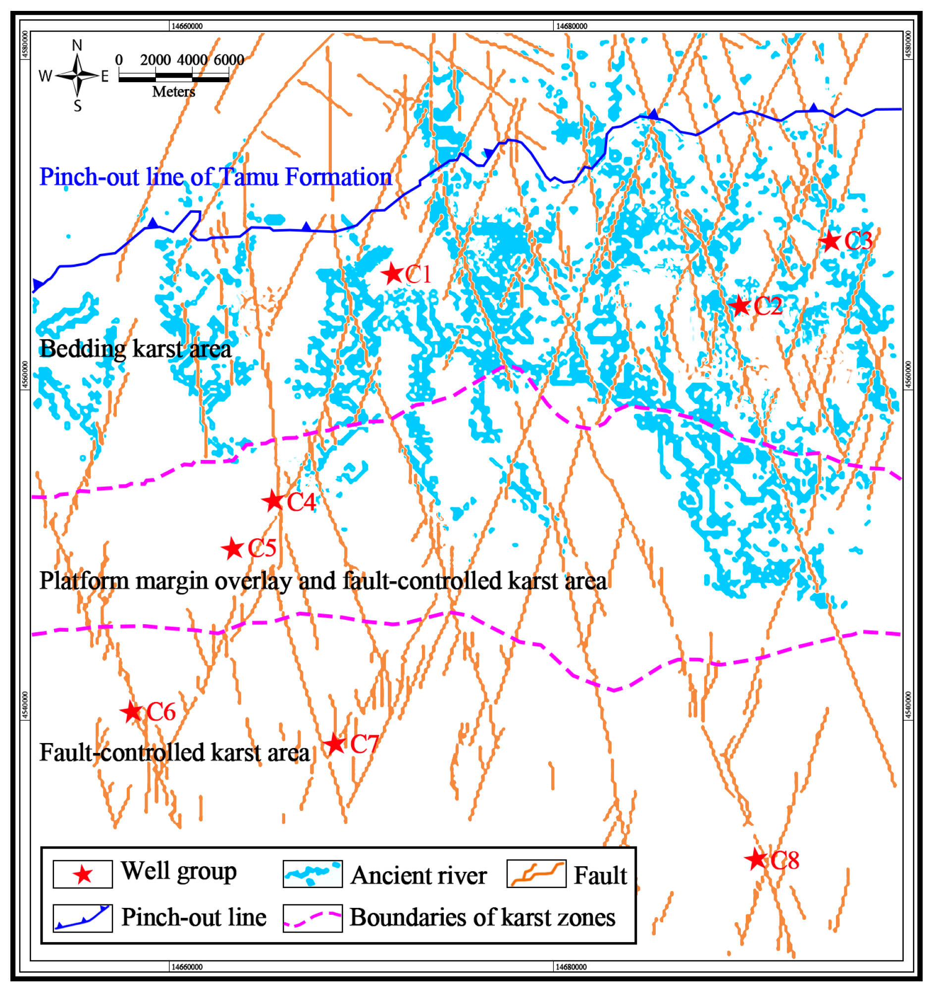
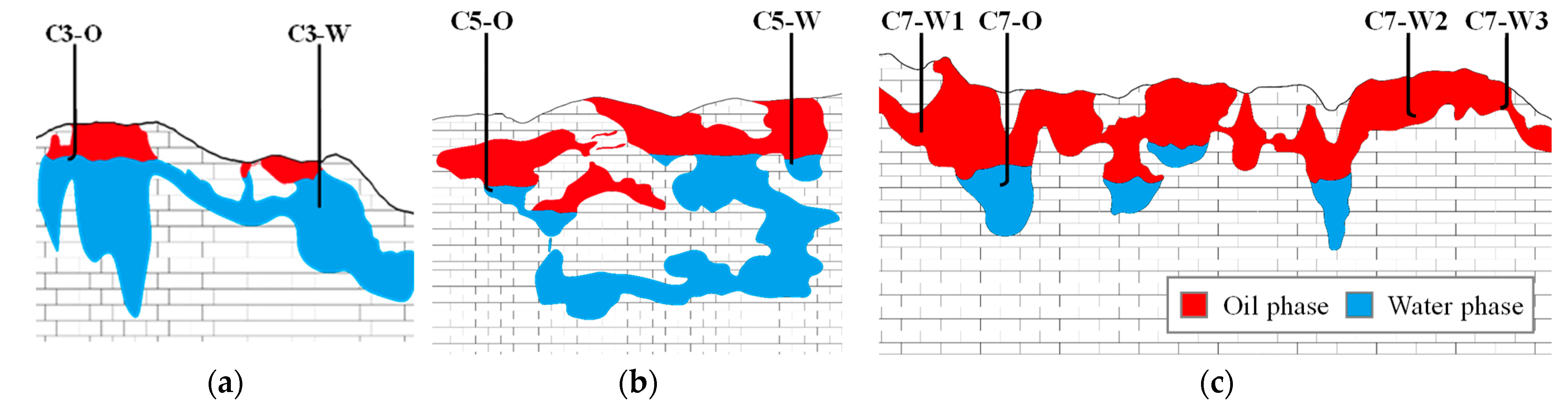
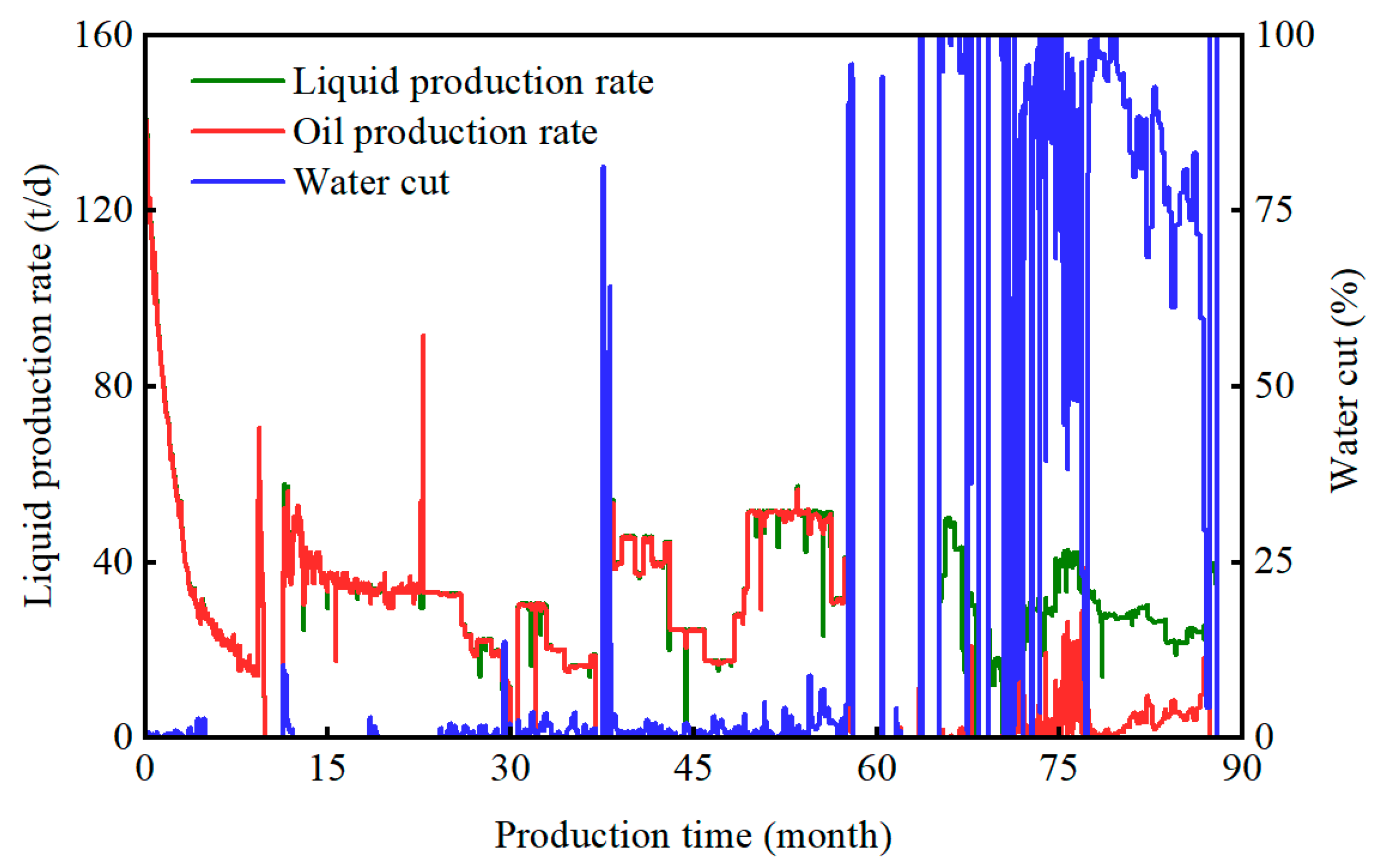
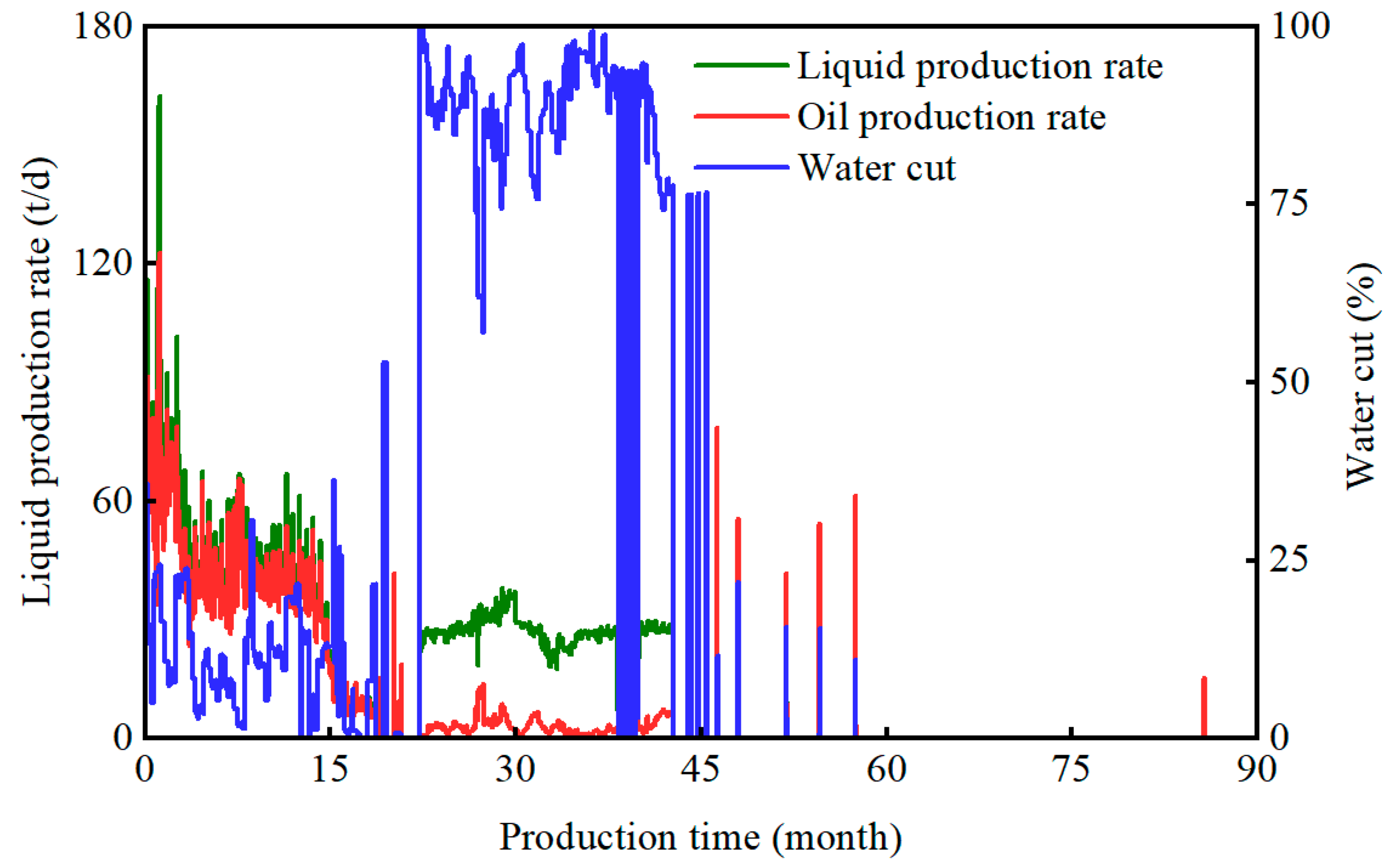
2. Production Dynamics of Different Karst-Controlled Fractured-Vuggy Units

The study area is located in C oilfield, in the Tarim Basin of China. It is an ultra-deep (6000–8000 m), ultra-high pressure (>100 MPa) marine fractured-vuggy carbonate reservoir, and the major producing layers are the Ordovician Lianglitage Formation, Yijsianfang Formation, and Yingshan Formation, respectively. After multi-stage karstification in the middle Caledonian, early Hercynian, and late Hercynian, three types of karst-controlled fractured-vuggy formations developed from north to south: bedding karst zone, platform margin overlay and fault-controlled karst zone, and fault-controlled karst zone. These three types of karst zones are vertically located in the upper karst gentle slope, lower karst gentle slope, and karst basin formed during the karstification stage of the Lianglitage Formation. They are the runoff and drainage areas of the paleo-karst basin. The planar distribution of karst-controlled zones is shown in Figure 1, and the vertical distribution of typical fractured-vuggy units under different karst patterns is shown in Figure 2. The early development stage of the target reservoir was dominated by elastic energy and natural water flooding, with a primary recovery of only 6~8%. In order to inhibit the high decline rate in oil production caused by the formation of energy deficit and the rapid rise in water cut, water or gas injection has been explored for the efficient exploitation of multi-well fractured-vuggy units in practice. However, despite a limited understanding of the spatial structure of fractured-vuggy units, it is clear that the production dynamic characteristics of different karst-controlled fractured-vuggy units differ significantly.
C3 is a typical bedding karst-controlled fractured-vuggy unit in the northern area; its seismic profile shows a strong reflection characteristic of “beading”, indicating that the major reservoir spaces of this unit are large-scale cavities. There were two wells drilled through the C3 fractured-vuggy unit: C3-W and C3-O, both of which were in flowing production during the early stage of development. C3-W well had low natural energy and was shut down due to low production after 30 days; it was later converted to a water injector. Figure 3 shows the production dynamic curve of C3-O producer. It can be seen that in the water-free stage, the formation energy was rapidly depleted, and the oil production rate decreased sharply. After two rounds of water injection, the value of water cut increased slightly. In addition, after well C3-W was converted to an injector, the production performance of well C3-O was effectively improved. After five years of continuous production, the water cut increased from 5.71% to 94.6%, and the oil production rate decreased from 33 t/d to 2.9 t/d. The analysis showed that serious water channeling occurred during water injection. Using rate transient analysis, the dynamic geological reserve of the C3 fractured-vuggy unit is 9.3 × 10⁴ t; the cumulative oil production is 5.9 × 10⁴ t, and the oil recovery degree is 63.5%.
C5 is a typical fractured-vuggy unit located in a central platform margin overlay and fault-controlled karst zone. Its seismic profile shows strong characteristics of “beads + sheet”, indicating that this unit mainly consists of fractured-vuggy reservoir bodies. There were two wells drilled through the C5 fractured-vuggy unit: C5-W and C5-O. The C5-W well was first put into operation with an electric pump, and water cut was about 80% when it was opened. After operating for a period, a second electric pump was added; the water cut jumped to more than 90%, and it was then converted to an injector. Figure 4 shows the production dynamic curve of well C5-O. It can be seen that the water cut of well C5-O is about 30% in the flowing production stage, and it quickly jumps to more than 90% after mining. After almost 50 months of continuous production, the well C5-O was shut down due to little productivity. Using rate transient analysis, the dynamic geological reserve of C5 fractured-vuggy unit is 76.2 × 10⁴ t; the cumulative oil production is 3.9 × 10⁴ t, and the recovery degree is only 5.1%.
C7 is a typical fault-controlled fractured-vuggy unit located in the south karst area. Large amounts of fractures are well distributed, and karst fractured-vuggy bodies typically occur along the faults. The seismic profile shows a reflection characteristic of “beading”, and the karst indicators are scattered and massive, indicating that the C7 unit is mainly occupied by fractured-vuggy reservoir bodies. The C7 unit consists of four wells: C7-W1, C7-W2, C7-W3, and C7-O. The first three wells have been converted to injectors since production. Thus, there are currently three injectors and one producer. Figure 5 exhibits the production dynamic curve of well C7-O. It can be seen that the liquid production rate decreased slowly in the early stage, but almost remained unchanged after the nozzle was enlarged. There is little water produced from C7-O, indicating that the bottom water is not active. Based on rate transient analysis, the dynamic geological reserve of C7 fractured-vuggy unit is 304.6 × 10⁴ t; the cumulative oil production is 21.4 × 10⁴ t, and the recovery degree is about 7%.
In accordance with the above methodology, the dynamic and static characteristics of the other five fractured-vuggy units under different karst patterns are analyzed. The results show that the large-scale cavities mainly occur in the northern bedding karst zone, and the water-free oil production period is long, but the natural water energy is insufficient, which leads to a serious formation pressure deficit in the early production stage of depletion. Well shut-in induced by high water cut is becoming the greatest challenge to hinder increasing oil production. Fractured-vuggy reservoir bodies mainly occur in the central platform margin overlay and fault-controlled karst zone, with strong liquid supply capacity, but the bottom water breakthrough is quick, typically leading to a relatively short water-free production period and a recovery degree of less than 10%. Water control to achieve high oil production should be considered in the follow-up stage. The karst fractured-vuggy reservoir bodies usually occur along the faults in the southern fault-controlled zone, whose heterogeneity is significant. With regard to different fault-controlled fractured-vuggy units, the production dynamic characteristics differ greatly, and the adjustment strategies should be systematically determined based on the configuration of fractured-vuggy bodies, water energy, well-storage allocation, and other influential factors of each unit. Considering factors such as reservoir types, aquifer size, and production dynamic characteristics, three typical well groups, C3, C5, and C7, have been selected for further research.

3. Numerical Simulation Method for Fractured-Vuggy Reservoirs Considering the Vertical Equilibrium Mechanism

The distribution patterns of fractures and cavities in fractured-vuggy carbonate reservoirs differ greatly, and the connectivity between cavities and fractures is extremely complex. During the development of fractured-vuggy reservoirs, the oil and water spontaneously diverge gravitationally in the vertical direction, and the water will spontaneously sink to the bottom without any external power, and the oil will float to the top, so the vertical equilibrium phenomenon is very prominent. In a published paper [44], the author established an equivalent numerical simulation method for fractured-vuggy reservoirs considering the vertical equilibrium mechanism, and the comparison between the experimental and simulation results shows that the method is highly accurate and is very useful for revealing the remaining oil distribution and fluid flow characteristics of karst fractured-vuggy reservoirs.
For karst fractured-vuggy carbonate reservoirs, the mathematical model of oil-water flow considering the vertical equilibrium mechanism mainly includes the continuity equation, the equation of motion, and the auxiliary equation, which can be described as follows:
t ( ρ w ϕ s w ) + ( ρ w u w ) = ρ w q w
t ( ρ o ϕ s o ) + ( ρ o u o ) = ρ o q o
u o = k k r o μ o ( p o ρ o g Δ z )
u w = k k r w μ w ( p w ρ w g Δ z )
s w + s o = 1
p o = p w + p c ( s w )
k r o = k r o ( s w )
k r w = k r w ( s w )
When a numerical simulation grid is vertically equilibrated, the saturation distribution and pressure distribution in the grid need not be solved numerically, and the oil and water phase distributions in the grid can be calculated according to the material conservation equation.
According to the vertical equilibrium assumption, the fluid pressure satisfies the hydrodynamic static equilibrium relation:
p α ( x , y , z , t ) = P α ( x , y , t ) + ρ α g ( z z B )
The equations below introduce the vertical integration variables:
Φ ( x , y ) = z B z T ϕ ( x , y , z ) d z
S α ( x , y , t ) = 1 Φ z B z T ϕ ( x , y , z ) s α ( x , y , z , t ) d z
U α = z B z T u α , d z
Q α = z B z T q α d z
K = z B z T k d z
Λ α = K 1 z B z T k λ α d z
where α = w; o is the phase; subscripts T and B denote the top and bottom, respectively; p α is the pressure of phase α in a coarse grid equal to the pressure of z B at the bottom of the grid; λ α = k r α μ α is the fluency of α phase; is the (x, y) plane.
By substituting the above integral variables into the continuity equation and the equation of motion, it is organized as
( Φ S α ) t + c α Φ S α P α t + U α = Q α ( u α , T u α , B ) = Ψ α
U α = K Λ α ( P α ρ α g Δ z )
where c α = 1 ρ α d ρ α d P α is the fluid compressibility.
The saturation S α and pressure P α at the coarse grid scale are estimated by solving a system of vertically integrated equations, and then the saturation and pressure at the fine grid scale are reconstructed based on the vertical equilibrium calculation. The vertical equilibrium model assumes that the fluid reaches gravitational equilibrium instantaneously, and the application effect depends on the relationship between the vertical equilibrium time t s e g and the simulation step size T ; if t s e g is much smaller than T , then the vertical equilibrium model approximation works well; otherwise, the vertical equilibrium model is not applicable.
The author used a 3D-printed fractured-vuggy physical simulation model, conducted a large number of vertical equilibrium time test experiments, used multiple nonlinear regression methods, and established a vertical equilibrium time prediction model applicable to karst fractured-vuggy media; the application effect is remarkable, and the expression is as follows:
y = 0.0573 0.0152 x 1 + 0.0644 x 2 + 0.0289 x 3 0.0006 x 1 x 2 0.0007 x 1 x 3 + 0.002 x 2 x 3 + 0.0003 x 1 2 0.0038 x 2 2 + 0.0005 x 3 2
where y is the vertical equilibrium time, in hours; x1 is the fracture width, in μm; x2 is the crude oil viscosity, in mPa·s; x3 is the model height, in cm.

4. Determination of the Optimal Development Strategies

As mentioned above, the dynamic characteristics of fractured-vuggy units in different karst formations are quite different. In order to further reveal the influence of karst patterns on the development potential of fractured-vuggy carbonate reservoirs, the numerical simulation models reflecting the reservoir connectivity were established based on the three karst patterns, bedding karst, platform margin overlay and fault-controlled karst, and fault-controlled karst. The physical properties of rock and fluid are summarized in Table 1. Oil-water two-phase relative permeability curve, permeability, porosity, and other sensitive parameters were adjusted to achieve production history matching and reveal the spatial distribution of remaining oil. Then, using reservoir numerical simulation, the effects of water flooding, periodic water injection, gas flooding, periodic gas injection, water alternating gas injection, and cyclic N2 huff-n-puff injection were compared in order to determine the reasonable development strategies by considering the influence of different karst patterns.

4.1. Bedding Karst Fractured-Vuggy Unit

The reservoir numerical simulation model of C3 fractured-vuggy unit in the bedding karst zone takes O3t and O1-2y2 as the top and bottom; the grid step size is 25 × 25 × 3 m, and the total grid number is 68 × 61 × 150 = 622,200. The three-dimensional distribution of oil and water after production history matching is shown in Figure 6. Affected by the surface and underground river and interwell filling, there is attic remaining oil in the upper part of producer C3-O, and there is a large amount of well-spacing type remaining oil along interwell flow channels. Based on analysis of fractured-vuggy spatial structure and dynamic evolution of fluid saturation field, it can be concluded that the well-spacing type remaining oil is dominant in C3 bedding karst fractured-vuggy unit.
During the numerical simulation, the total injected pore volume was 0.4 PV, and the cumulative simulation time was 5 years. Figure 7 reflects the incremental oil recovery performance obtained by six gas or water injection methods. It can be seen that the water alternating gas (WAG) injection achieves the best oil increase effect. Figure 8 shows the dynamic evolution of oil, gas, and water saturation distribution in the process of WAG injection. The comparison shows that the injected gas first forms a secondary gas cap at the top of C3-W well, and the remaining oil at the top is displaced downward. After the remaining oil at the top of C3-W well reaches the fractured-vuggy joint, driven by the pressure drop and bottom water, it flows through the joint into the fractured-vuggy system of C3-O well, causing the oil-water interface around C3-O well to move down, and the remaining oil at the top can be effectively recovered. Once the gas-liquid interface of C3-W well reaches the joint, gas channeling flows to the fractured-vuggy system of C3-O well due to density differences, forms a gas cap, and then continues to drive the remaining oil at the top downward. After 3 years of production, injected N2 escapes from the wellhead of C3-O, resulting in a decrease in liquid production rate and poor oil increase effect.
In order to reveal the underlying EOR mechanism of gas or water injection to C3 karst fractured-vuggy unit, dynamic curves of different injection methods were further compared, as shown in Figure 9. It can be seen that when water alternating gas injection is implemented, the water cut of C3-O well decreases first and then increases, and the oil replacement ratio increases first and then decreases gradually, and the incremental oil recovery degree increases first and then stabilizes. The inflection points of these three curves all occurred around the 36th month, and the curve trend changes were consistent with the evolution of saturation field. The analysis shows that in the early stage of development the injected gas forms the secondary gas top to displace the remaining oil at the top, reduces the oil-water interface, and slows down the coning of bottom water. The main mechanisms of WAG injection are to supply the bottom water energy and increase the driving force of the remaining oil. Both water cut and oil replacement ratio during waterflooding and periodic water injection increased slowly, indicating that the oil-water interface had risen to the bottom of well C3-O and an invalid circulation of injected water had occurred. During periodic gas injection, it is difficult to control water effectively, resulting in a generally high water cut and low incremental oil recovery degree. In the process of N2 huff-n-puff, the oil replacement ratio is high, but due to the influence of the complicated fractured-vuggy connectivity, serious gas channeling occurs in the later stages, and only part of the remaining oil at the top can be recovered. In the late stage of gas flooding, liquid production rate drops sharply due to severe gas channeling, and the EOR is lower than that of WAG injection.
It can be seen that the fractured-vuggy units in the bedding karst zone typically has good physical properties and great oil-increasing potential. A large amount of remaining oil has formed at the top of fractured-vuggy bodies due to the influence of complicated reservoir connectivity, filling degree, and well-storage configuration relationship. In later stages of water flooding, the bottom water coning is severe, the oil replacement ratio of water flooding is relatively low, and the incremental oil recovery effect is poor. The oil replacement ratio of gas injection is high, but inevitable gas channeling usually leads to limited incremental oil recovery. WAG injection can effectively slow down the speed of gas channeling, and injected water can increase driving force of bottom water, which shows the most significant EOR effect, and is selected as the optimal development strategy.

4.2. Platform Margin Overlay and Fault-Controlled Karst Fractured-Vuggy Unit

O3t Yijianfang Formation and O1-2y2 are taken as the top and bottom in the numerical simulation model of the C5 fractured-vuggy unit located in the platform edge overlay and fault-controlled karst zone. The grid step size is 20 × 20 × 3.0 m, and the total grid number is 40 × 74 × 150 = 444,000. From the oil-water distribution after production history matching (see Figure 10), it can be seen that due to the local low-permeability blocking effect, there is a large amount of remaining oil at the top of two vugs, which is defined as local blocking type remaining oil. The oil-water interface near well C5-O is already higher than that at the perforation, with abrupt water rising in the late stage of water flooding. To effectively displace the remaining oil, the C5-O well was first drilled for sidetracking.
In the numerical simulation process, the total pore volume injected was 0.2 PV, and the numerical simulation lasted for 5 years. Figure 11 reflects the incremental oil recovery performance obtained by six gas or water injection methods. It can be seen that N2 huff-n-puff achieves the greatest EOR effect. The dynamic change in fluid saturation distribution is shown in Figure 12. The analysis shows that the injected N2 preferentially forms a secondary gas top at the top of well C5-O, affected by local blocking to displace the remaining oil at the top downward, depresses the oil-water dynamic interface, and inhibits bottom water coning. As N2 injection continues, the gas-liquid interface gradually decreases, and N2 flows into the adjacent fractured-vuggy system. The gas cap at the top of C5-O well no longer changes, and N2 injection mainly exploits the remaining oil at the top of the intermediate fractured-vuggy system.
In order to reveal the underlying EOR mechanism of gas or water injection in C5 fractured-vuggy unit, the dynamic curves obtained using different injection methods are further compared, as shown in Figure 13. It can be seen that in the process of N2 huff-n-puff, the water cut decreases slightly after N2 injection and then rises slowly. The water cut achieved by N2 huff-n-puff is lower than that of other injection methods, indicating that N2 injection significantly inhibits bottom water coning. The oil displacement ratio decreases gradually as cycles of N2 huff-n-puff increase, indicating that the EOR effect of N2 huff-n-puff mainly occurs in the first few cycles. The water cut, replacement ratio, and incremental oil recovery degree of other injection methods are consistent because the injected fluid is only retained around the C5-W well, and the adjacent fractured-vuggy system is unexploited due to the influence of local blocking, regardless of whether gas injection or water injection is used. The main mechanism of increasing oil production is to expand the volume of bottom water or gas cap, supplement the formation energy around the injector, and drive the remaining oil to flow into the producer. The energy loss is great in the process of pressure wave propagation, and the EOR effect via the other five injection methods is lower than that of N2 huff-n-puff.
Studies show that due to the existence of multiple types of fractures in the platform margin overlay and fault-controlled karst zone, the flow rate of injected fluid is fast, but local blocking hinders the connectivity between producers and injectors, which renders the oil increase effect of gas or water injection from well C5–W, while the oil replacement ratio of N2 huff-n-puff from well C5-O is relatively high. For C5 karst fractured-vuggy unit, N2 huff-n-puff is ultimately identified as the optimal development strategy.

4.3. Fault-Controlled Karst Fractured-Vuggy Unit

O3T and O3T + 120 m are taken as the top and the bottom in the numerical simulation model of C7 fracture-vuggy unit located in the fault-controlled karst zone. The grid step size is 25 × 25 × 2.5 m, and the total grid number is 151 × 216 × 150 = 4,892,400. The 3D distribution of oil and water after production history matching is shown in Figure 14. The analysis shows that the remaining oil is continuously distributed along the upper part of the fault zone, which is defined as the upper continuous type.
In the numerical simulation process, the total pore volume injected is set to 0.1 PV, and the cumulative simulation time is 5 years. Figure 15 reflects the incremental oil recovery performance obtained using six gas or water injection methods. It can be seen that the best EOR effect is achieved by periodic gas injection. The dynamic change in saturation distribution during periodic gas injection is shown in Figure 16. It can be seen that nitrogen accumulates at the top of each injector to form a secondary gas cap, and the remaining oil at the top is driven to the C7-O well under pressure drop. After 1 year of production, the bottom water around the C7-O well is recovered.
In order to reveal the underlying mechanism of gas or water injection in C7 fractured-vuggy unit, the dynamic curves of different injection methods are further compared, as shown in Figure 17. It can be seen that under periodic gas injection, the water cut decreases rapidly and the oil replacement ratio equals nearly 100%, and the EOR effect of remaining oil is the most significant. Periodic water injection also exhibits similar production dynamic characteristics, while the oil replacement ratio and EOR degree of water flooding, gas flooding, and WAG injection are lower than those of periodic gas or water injection. The analysis shows that due to the large-scale dynamic geological reserves and underdeveloped bottom water, injection intensity is a key factor affecting development effect, and the existence of fractures further improves the reservoir connectivity. Compared with those of gas or water flooding, a larger injection intensity usually occurs in periodic injection, resulting in a better development effect. In the process of N2 huff-n-puff, the existence of fractures will allow the injected N2 to easily escape to the surrounding areas, and a secondary gas cap is not easily formed. This makes it difficult to recover the remaining oil at the top, and the overall driving effect of N2 huff-n-puff is relatively poor.
This study shows that the fracture system is well distributed in the fault-controlled karst zone, and large amounts of corrosion vugs exist along the fractures. Due to the significant energy loss of pressure wave propagation between injectors and producers, injection intensity is the main influential factor for EOR effect. Compared with gas or water flooding, periodic injection with higher injection intensity is more effective to improve the production performance of fault-controlled karst fractured-vuggy units.

5. Optimization of Injection-Production Parameters

For different karst-controlled fractured-vuggy carbonate reservoirs, the dynamic evolution of characteristic parameters such as oil replacement ratio, water cut, and incremental oil recovery degree under different gas or water injection methods all differ significantly. In order to further improve production performance, once the optimal development strategy is determined, reservoir numerical simulation is performed to optimize the key injection-production parameters such as total pore volume injected, injection-production ratio, gas-water ratio, and injection mode to clarify the underlying influence of different fractured-vuggy karst patterns.

5.1. Bedding Karst Fractured-Vuggy Unit

The optimal development strategy of C3 fractured-vuggy unit in the bedding karst zone is water alternating gas injection as concluded above. The basic injection-production parameters are as follows: the total pore volume (PV) injected is 0.4 PV; the injection-production ratio is one; the gas-water ratio is one, and the WAG injection duration is 60 days. In this study, the above-mentioned four key injection-production parameters are changed, and each parameter takes five levels. Numerical simulation is performed to investigate the influence of different key parameters on oil-increasing effect during WAG injection, as shown in Figure 18. As seen from Figure 18a, with the increase in PV injected, the recovery first increases and then decreases, which is mainly because of the low injection intensity and heavy formation deficit, resulting in poor fluid supply capacity and low incremental oil recovery degree of producers. As injection intensity becomes larger, gas is easily expelled, water cut rises rapidly, and liquid production rate gradually decreases, which affects the oil-increasing effect. Figure 18b indicates that when the injection-production ratio is less than 0.7, the incremental oil recovery degree almost remains unchanged; When the injection-production ratio is greater than 0.7, the oil recovery increases slowly with the increase in injection-production ratio. This is because when the injection-production ratio increases but the total PV injected remains unchanged, the cumulative liquid production decreases, and the oil recovery tends to be stable. From Figure 18c, it can be seen that with the increase in gas-water ratio, the increases in oil recovery degree first drops and then rise gradually. It demonstrates that the injected gas is more likely to escape with a larger gas-water ratio. As the gas-water ratio decreases, the cumulative gas injection reduces, and the EOR effect of gas flooding on crude oil is weakened, resulting in a smaller increase in oil recovery. Once the gas-water ratio is less than 1:2, injected water will become the major driving force to effectively recovers the well-spacing type remaining oil. In Figure 18d, it can be observed that the WAG injection duration has little effect on the EOR effect of C3 bedding karst fractured-vuggy unit. In summary, the optimal injection-production parameters of WAG injection to C3 fractured-vuggy unit are described as follows: the total PV injected is 0.61 PV; the injection-production ratio is 0.7, and the gas-water ratio is 2:1.

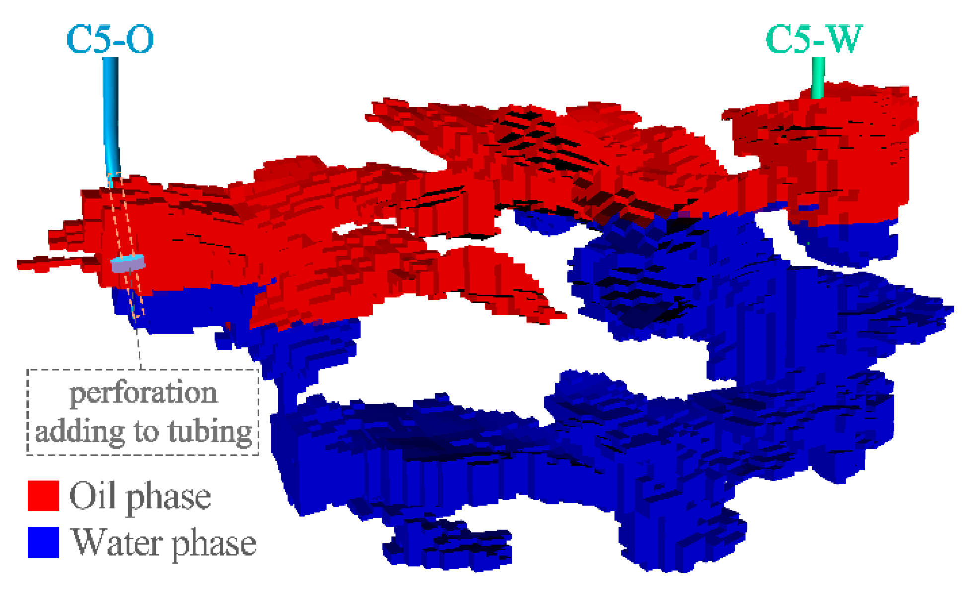
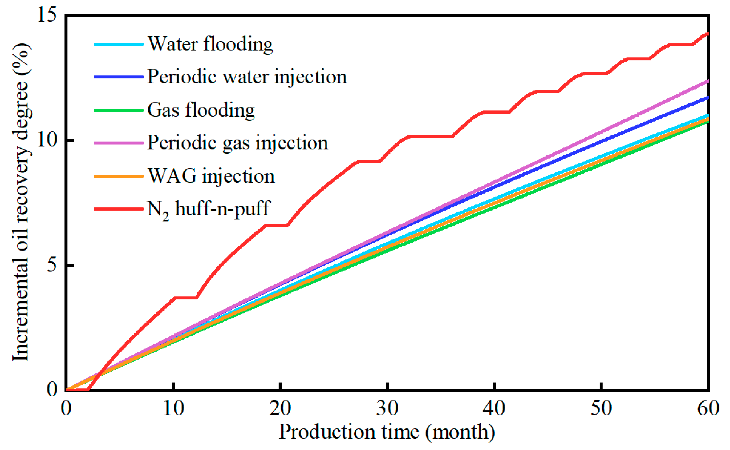
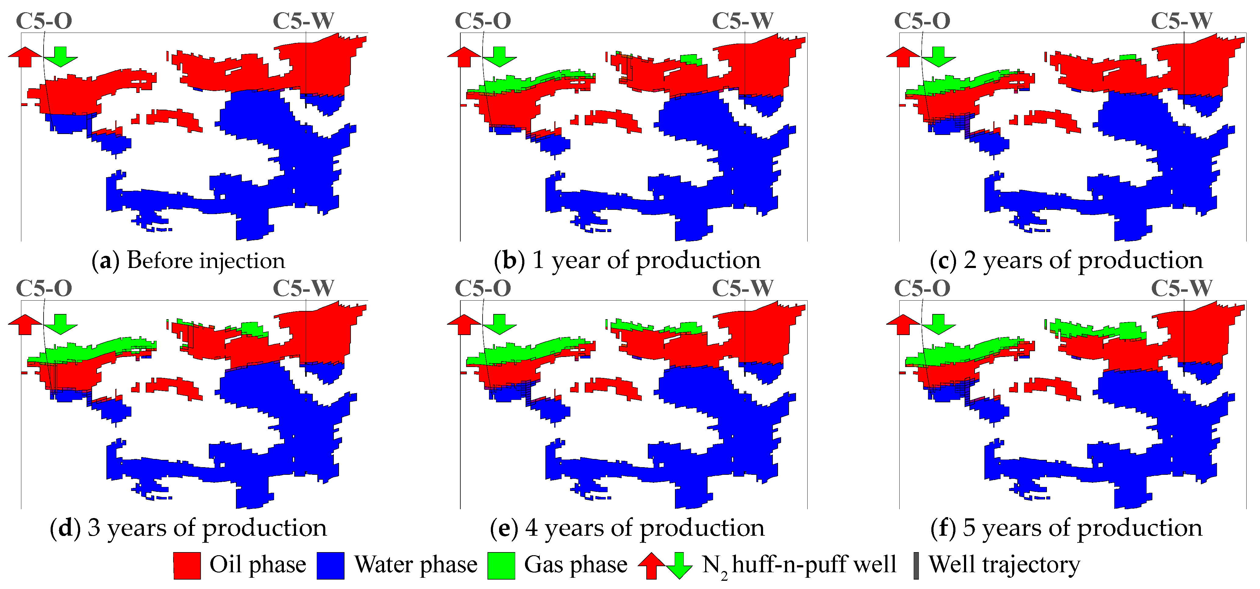
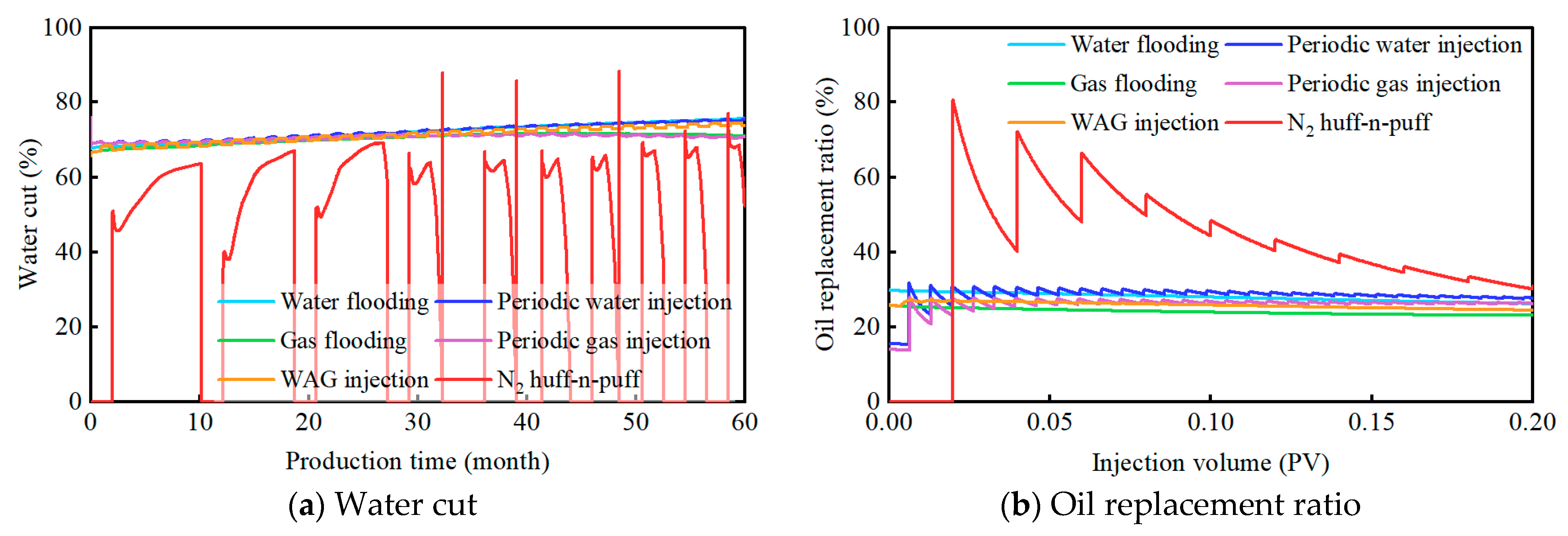
5.2. Platform Margin Overlay and Fault-Controlled Karst Fractured-Vuggy Unit

As can be concluded, the optimal development strategy of C5 fractured-vuggy unit in the platform margin overlay and fault-controlled karst zone is cyclic N2 huff-n-puff. The basic injection-production parameters are summarized as follows: the total PV injected is 0.2 PV; the injection-production ratio is one; the soaking time is 30 days, and the cycle of huff-n-puff is 10. In this study, four key parameters including total PV injected, injection-production ratio, soaking time, and cycle of huff-n-puff are changed, and each parameter is taken at five levels. Numerical simulation is used to investigate the effects of different injection-production parameters on the oil-increasing effect of C5 fractured-vuggy unit by N2 huff-n-puff, as shown in Figure 19. It can be seen from Figure 19a that the incremental oil recovery degree grows with a higher PV injected, and the recovery increase tends to be stable once the total PV injected is larger than 0.4 PV. It also shows that more remaining oil can be effectively recovered from the top of the fractured-vuggy unit with a larger PV injected with the process of N2 huff-n-puff. As shown in Figure 19b, with the increase in the injection-production ratio, oil recovery increases steadily at first and then decreases; this is because the formation energy is severely depleted under a low injection-production ratio (<0.4), which leads to a failure in continuous increase in liquid production. When injection-production ratio is larger than 0.4, liquid production rate is relatively low, and the incremental oil recovery degree gradually drops. It can be seen from Figure 19c that the oil-increasing effect first rises and then falls with a longer soaking time. The soaking time mainly affects the replacement of oil, gas, and water in reservoir. A short soaking time implies insufficient fluid replacement and a limited incremental oil recovery degree. If the soaking time is too long, N2 is prone to escape along fractures in the process of oil–gas–water replacement, indicating that there is an optimal soaking time for cyclic N2 huff-n-puff. As shown in Figure 19d, the oil-increasing effect rises first and then drops as cycle of huff-n-puff becomes larger. This is because in a given production period, the larger the cycles of huff-n-puff, the longer the cumulative time of gas injection and well soaking and the shorter the actual production time, and the oil-increasing effect will be affected. With fewer cycles of N2 huff-n-puff, the injection intensity of each cycle increases, and N2 injection more easily escapes along fractures, thus resulting in a decrease in EOR effect. This implies that there is an optimal cycle of N2 huff-n-puff. In summary, the optimal injection-production parameters of cyclic N2 huff-n-puff in C5 fractured-vuggy unit are described as follows: the total PV injected is 0.4 PV; the injection-production ratio is 0.4; the soaking time is 20 days, and the cycle of huff-n-puff is 10.

5.3. Fault-Controlled Karst Fractured-Vuggy Unit

As concluded above, the optimal development strategy of C7 fractured-vuggy unit in the fault-controlled karst zone is periodic gas injection. The basic parameters of periodic gas injection are as follows: the total PV injected is 0.1 PV; the injection-production ratio is 1.0; the periodic injection duration is 60 days, and the equivalent injection mode is used. In this study, four key parameters, i.e., total PV injected, injection-production ratio, periodic injection duration, and injection mode, are changed. Here, three injection modes including “long injection and short stop”, “equivalent injection”, and “short injection and long stop” are considered. Other influential parameters are taken at five levels, and numerical simulation is used to investigate the influence of different injection-production parameters on the oil-increasing effect of C7 fractured-vuggy unit with periodic gas injection, which is shown in Figure 20. It can be seen from Figure 20a that with the increase in total gas injection, the incremental oil recovery degree first rises and then tends to be stable. If total gas injection is too small, the insufficient replenishment of formation energy deficit typically results in a limited oil-increasing effect. When total gas injection reaches a certain value, gas preferentially migrates along the top of a targeted reservoir body due to gravity overlap. Once the displacement front reaches the bottom of producer, the ineffective circulation of injected gas will occur, and the oil-increasing effect is stabilized. As shown in Figure 20b, if the injection-production ratio exceeds a certain critical value, a low liquid production rate will lead to a fall in the oil-increasing effect of cyclic gas injection. As seen from Figure 20c,d, periodic injection duration has little effect on recovering the remaining oil in C7 fault-controlled fractured-vuggy unit. Compared with the two methods, “long injection and short stop” and “equivalent injection”, the “short injection and long stop” process can achieve a better oil-increasing effect due to higher gas injection intensity and longer oil and gas replacement period. In summary, the optimal injection-production parameters for periodic gas injection in C7 fractured-vuggy unit are described as follows: the total PV injected is 0.1 PV; the injection-production ratio is one; the periodic injection duration is 50 days, and the injection mode of “short injection and long stop” is recommended.
The optimal injection-production parameters of the other five fractured-vuggy units are studied, and the relationships between karst fractured-vuggy pattern, remaining oil distribution, and reasonable development strategies are summarized in Table 2. It demonstrates that, for typical fractured-vuggy units with the same karst patterns, the type of reservoir space is nearly consistent, the development strategies, and the underlying effect of injection-production parameters are also similar. However, due to strong heterogeneity, complicated fluid dynamic, and oil-water allocation relationship in actual karst fractured-vuggy carbonate reservoir, studies on reasonable development strategy and optimal injection-production parameters of specific karst-controlled fractured-vuggy unit should also be performed using static and dynamic analysis.

6. Conclusions

Taking the eight typical fracture-vuggy units under three types of karst patterns in C oilfield in the Tarim Basin of China as an example, based on the newly proposed numerical simulation method of fluid vertical equilibrium and the influence of karst pattern on production dynamic characteristics, the remaining oil morphology pattern, reasonable development strategy, and key injection-production parameters are analyzed. The conclusions are as follows:
For typical fractured-vuggy units with different karst patterns, the complexity of key factors such as spatial structure, reserve scale, and oil-water allocation relationship aggravates the heterogeneity of reservoirs, leading to a great difference in development dynamic patterns. In the northern bedding karst-controlled zone, the major reservoir space is the large-scale cavity, and the water-free production period is relatively long. Fractured-vuggy reservoir bodies are mainly distributed in the central platform margin overlay and fault-controlled karst zone, with strong liquid supply capacity, but the breakthrough of bottom water is rapid, and the water-free period is very short. In the southern fault-controlled karst zone, fractured-vuggy bodies occur along the faults; the bottom water is underdeveloped, and a rapid decline of oil production usually occurs in the depletion-drive stage, and the well produces almost no water.
After water flooding, well-spacing type and local blocking type of remaining oil mainly occur in the northern bedding karst-controlled zone. The remaining oil is widely distributed in the platform margin overlay, and fault-controlled karst zone is attic type, while the upper continuous-type remaining oil occurs mainly in the southern fault-controlled karst zone.
For the northern bedding karst zone, the optimal development strategy to improve the effect of water or gas injection is influenced by a combination of spatial structure of fractured-vuggy bodies and reservoir connectivity structural patterns. Among which, cyclic N2 huff-n-puff is recommended for the C1 fractured-vuggy unit; WAG injection is more suitable for the C3 fractured-vuggy unit, and periodic water injection is recommended for the C2 fractured-vuggy unit. For the southern fault-controlled karst zone, periodic gas injection or cyclic N2 huff-n-puff is preferred to exploit the upper continuous-type remaining oil. The fractured-vuggy karst patterns also have an important effect on the optimal level of injection-production parameters for water or gas injection development strategies.

Author Contributions

Methodology, Q.W. (Qi Wang); Software, J.Z.; Resources, C.Y.; Data curation, F.C.; Project administration, M.L.; Funding acquisition, Q.W. (Qinghong Wang) All authors have read and agreed to the published version of the manuscript.

Funding

This work is funded by the National Natural Science Foundation of China (Grant No. 52074344), and PetroChina Science and Technology Project (2024DJ1004 and 2023ZZ16YJ02).

Data Availability Statement

The original contributions presented in the study are included in the article; further inquiries can be directed to the corresponding author.

Acknowledgments

The authors thank all the anonymous reviewers for their insight comments which have greatly improved the quality of this paper. The authors thank Chen Jin and Wang Daigang from China University of Petroleum (Beijing) for their contributions in this work.

Conflicts of Interest

The authors declare no conflicts of interest.

References

  1. Garland, J.; Neilson, J.; Laubach, S.E.; Whidden, K.J. Advances in carbonate exploration and reservoir analysis. In Advances in Carbonate Exploration and Reservoir Analysis; Geological Society, London, Special Publications: London, UK, 2012; Volume 370, pp. 1–5. [Google Scholar]
  2. Zhao, W.; Shen, A.; Qiao, Z.; Zheng, J.; Wang, X. Carbonate karst reservoirs of the Tarim Basin, northwest China: Types, features, origins, and implications for hydrocarbon exploration. Interpretation 2014, 2, SF65–SF90. [Google Scholar] [CrossRef]
  3. Li, Y.; Kang, Z.; Xue, Z.; Zheng, S. Theories and practices of carbonate reservoirs development in China. Pet. Explor. Dev. 2018, 45, 712–722. [Google Scholar] [CrossRef]
  4. Sheng, S.; Duan, Y.; Wei, M.; Yue, T.; Wu, Z.; Tan, L. Analysis of Interwell Connectivity of Tracer Monitoring in Carbonate Fractured-vuggy Reservoir: Taking T-Well Group of Tahe Oilfield as an Example. Geofluids 2021, 2021, 5572902. [Google Scholar] [CrossRef]
  5. Ahmatjan, A.; Zhong, J.; Li, Y.; Zhong, F.; Gao, Y. Study on Effect between karstification and Fracture in Carbonate Rocks. Geol. Rev. 2008, 54, 485–493. (In Chinese) [Google Scholar]
  6. Ni, X.F.; Zhang, L.J.; Shen, A.J.; Qiao, Z.F.; Han, L.J. Diagenesis and pore evolution of the Ordovician karst reservoir in Yengimahalla Hanilcatam region of Tarim Basin. J. Palaeogeogr. 2010, 12, 467–479. [Google Scholar]
  7. Wang, K.; Teng, J.; Deng, H.; Fu, M.; Lu, H. Classification of Void Space Types in Fractured-Vuggy Carbonate Reservoir Using Geophysical Logging: A Case Study on the Sinian Dengying Formation of the Sichuan Basin, Southwest China. Energies 2021, 14, 5087. [Google Scholar] [CrossRef]
  8. Li, Y. The theory and method for development of carbonate fractured-cavity reservoirs in Tahe oilfield. Acta Pet. Sin. 2013, 34, 115–121. [Google Scholar]
  9. Wang, Q.; Jiang, H.; Han, J.; Wang, D.; Li, J. Adaptive Prediction of Enhanced Oil Recovery by N2 huff-n-puff in Fractured-Cavity Reservoir Using an FNN-FDS Hybrid Model. Appl. Sci. 2021, 11, 8871. [Google Scholar] [CrossRef]
  10. Zhou, J.; Lyu, H.; Lin, Z.; Wu, C. Karstification models of the Ordovician carbonates and their influetial factors in the Tahe oilfield, the Tarim basin. Pet. Geol. Exp. 2009, 31, 547–550. [Google Scholar]
  11. Ni, X.; Zhang, L.; Shen, A. Characteristics and genesis of Ordovician carbonate karst reservoir in Yingmaili-Halahatang Area, Tarim Basin. Acta Sedimentol. Sin. 2011, 29, 465–474. [Google Scholar]
  12. Ni, X.; Zhang, L.; Shen, A.; Qiao, Z.; Zhao, K. Characteristics and karstification of the Ordovician carbonate reservoir, Halahatang area, northern Tarim Basin. Acta Petrol. Sin. 2012, 28, 815–826. [Google Scholar]
  13. You, X.; Sana, W.; Fan, X. The characteristics and main control factors of hydrocarbon accumulation of ultra-deep marine carbonates in the Tarim Basin, NW China—A review. Carpathian J. Earth Environ. Sci. 2018, 13, 135–144. [Google Scholar] [CrossRef]
  14. Zhang, Q. Development Mechanism of Ordovician Carbonate Paleokarst in the Halahatang Area of the Tarim Basin. Ph.D. Dissertation, China University of Geosciences, Wuhan, China, 2018. [Google Scholar]
  15. Firme, P.A.L.P.; Quevedo, R.J.; Roehl, D.; Pereira, L.C.; Cazarin, C.L. Mechanical behavior of carbonate reservoirs with single karst cavities. Geomech. Energy Environ. 2021, 25, 100209. [Google Scholar] [CrossRef]
  16. Wu, Y.-S.; Di, Y.; Kang, Z.; Fakcharoenphol, P. A multiple-continuum model for simulating single-phase and multiphase flow in naturally fractured vuggy reservoirs. J. Pet. Sci. Eng. 2011, 78, 13–22. [Google Scholar] [CrossRef]
  17. Liao, T.; Hou, J.; Chen, L.; Ma, K.; Yang, W.; Dong, Y. Evolutionary model of the Ordovician karst reservoir in Halahatang oilfield, northern Tarim Basin. Acta Pet. Sin. 2015, 36, 1380–1391. [Google Scholar]
  18. Wang, D.; Sun, J. Oil recovery for fractured-vuggy carbonate reservoirs by cyclic water huff and puff: Performance analysis and prediction. Sci. Rep. 2019, 9, 15231. [Google Scholar] [CrossRef]
  19. Wang, Y.; Jiang, H.; Li, J. Study on Water Injection Indicator Curve Model in Fractured Vuggy Carbonate Reservoir. Geofluids 2021, 2021, 5624642. [Google Scholar]
  20. Rong, Y.; Liu, X.; Yang, M. A Discussion on water flooding in the multi-well fractured-vuggy units of carbonate reservoirs in Tahe oilfield. Oil Gas Geol. 2010, 31, 28–32. [Google Scholar]
  21. Ma, X.; Liu, P.; He, C. Waterflooding Pattern for Fractured-Vuggy Reservoir in Tahe Oilfield, Tarim Basin. Xinjiang Pet. Geol. 2011, 32, 63–65. [Google Scholar]
  22. Ren, W.; Chen, X. Research on Asymmetric Unstable Water Injection in Fractured Carbonate Reservoirs. Sci. Technol. Eng. 2013, 13, 8120–8125. [Google Scholar]
  23. Rong, Y.; Li, X.; Liu, X.; Li, X. Discussion about pattern of water flooding development in multi-well fractured-vuggy units of carbonate fractured-vuggy reservoir in Tahe oilfield. Pet. Geol. Recovery Effic. 2013, 20, 58–61. [Google Scholar]
  24. Hu, G. Technological Policy Research of Cyclic Waterflooding in Fracture Cavity Carbonate Reservoir in Tahe Oilfield. Xinjiang Pet. Geol. 2014, 35, 59–62. [Google Scholar]
  25. Geng, J.; Xiao, L.; Yue, P.; Xiao, Y.; Yang, H.; Qu, S.; Wang, X. Evaluation Method of Water Injection Development Effects in Fractured Vuggy Carbonate Reservoirs: Case Study of FI7 Strike-Slip Fault Zone. Energies 2024, 17, 5611. [Google Scholar] [CrossRef]
  26. Chen, L.; Jia, C.; Zhang, R.; Yue, P.; Jiang, X.; Wang, J.; Su, Z.; Xiao, Y.; Lv, Y. High-pressure capacity expansion and water injection mechanism and indicator curve model for fractured-vuggy carbonate reservoirs. Petroleum 2024, 10, 511–519. [Google Scholar] [CrossRef]
  27. Hou, J.; LI, H.; Jiang, Y.; Luo, M.; Zheng, Z.; Zhang, L.; Yuan, D. Macroscopic three-dimensional physical simulation of water flooding in multi-well fractured-vuggy unit. Pet. Explor. Dev. 2014, 41, 717–722. [Google Scholar] [CrossRef]
  28. Zheng, S.; Liu, Z.; Qiu, L. Evaluation of Injected Water Utilization for Fractured-Vuggy Reservoirs in Tahe Oilfield. Xinjiang Pet. Geol. 2017, 38, 452–454. [Google Scholar]
  29. Wang, J.; Liu, H.; Ning, Z.; Zhang, H.; Hong, C. Experiments on water flooding in fractured-vuggy cells in fractured-vuggy reservoirs. Pet. Explor. Dev. 2014, 41, 74–81. [Google Scholar] [CrossRef]
  30. He, J.; Li, A.; Wu, S.; Tang, R.; Lv, D.; Li, Y.; Li, X. Experimental Investigation on Injection and Production Pattern in Fractured-Vuggy Carbonate Reservoirs. Energies 2020, 13, 603. [Google Scholar] [CrossRef]
  31. Zhao, Y.; Lu, G.; Zhang, L.; Yang, K.; Li, X.; Luo, J. Physical simulation of waterflooding development in large-scale fractured-vuggy reservoir considering filling characteristics. J. Pet. Sci. Eng. 2020, 191, 107328. [Google Scholar] [CrossRef]
  32. Hou, J.-R.; Zheng, Z.-Y.; Song, Z.-J.; Luo, M.; Li, H.-B.; Zhang, L.; Yuan, D.-Y. Three-dimensional physical simulation and optimization of water injection of a multi-well fractured-vuggy unit. Pet. Sci. 2016, 13, 259–271. [Google Scholar] [CrossRef]
  33. Lyu, X.; Liu, Z.; Hou, J.; Lyu, T. Mechanism and influencing factors of EOR by N2 injection in fractured-vuggy carbonate reservoirs. J. Nat. Gas Sci. Eng. 2017, 40, 226–235. [Google Scholar] [CrossRef]
  34. Yang, J.; Hou, J.; Qu, M.; Liang, T.; Wen, Y. Experimental study the flow behaviors and mechanisms of nitrogen and foam assisted nitrogen gas flooding in 2-D visualized fractured-vuggy model. J. Pet. Sci. Eng. 2020, 194, 107501. [Google Scholar] [CrossRef]
  35. Yue, P.; Xie, Z.; Huang, S.; Liu, H.; Liang, S.; Chen, X. The application of N2 huff and puff for IOR in fractured-vuggy carbonate reservoir. Fuel 2018, 234, 1507–1517. [Google Scholar] [CrossRef]
  36. Belazreg, L.; Mahmood, S.M. Water alternating gas incremental recovery factor prediction and WAG pilot lessons learned. J. Pet. Explor. Prod. Technol. 2019, 10, 249–269. [Google Scholar] [CrossRef]
  37. Afzali, S.; Rezaei, N.; Zendehboudi, S. A comprehensive review on Enhanced Oil Recovery by Water Alternating Gas (WAG) injection. Fuel 2018, 227, 218–246. [Google Scholar] [CrossRef]
  38. Qu, M.; Hou, J.; Qi, P.; Zhao, F.; Ma, S.; Churchwell, L.; Wang, Q.; Li, H.; Yang, T. Experimental study of fluid behaviors from water and nitrogen floods on a 3-D visual fractured-vuggy model. J. Pet. Sci. Eng. 2018, 166, 871–879. [Google Scholar] [CrossRef]
  39. Akbari Aghdam, K.; Moghaddas, J.S.; Moradi, B.; Dabiri, M.; Hassanzadeh, M. Maximizing the Oil Recovery Through Miscible Water Alternating Gas (WAG) Injection in an Iranian Oil Reservoir. Pet. Sci. Technol. 2013, 31, 2431–2440. [Google Scholar] [CrossRef]
  40. Tafty, M.F.; Masihi, M.; Momeni, A. Recovery improvement using water and gas injection scenarios. Pet. Sci. Technol. 2011, 29, 290–300. [Google Scholar] [CrossRef]
  41. Panjalizadeh, H.; Alizadeh, A.; Ghazanfari, M.; Alizadeh, N. Optimization of the WAG injection process. Pet. Sci. Technol. 2015, 33, 294–301. [Google Scholar] [CrossRef]
  42. Sadeghnejad, S.; Manteghian, M.; Ruzsaz, H. Simulation Optimization of Water Alternating Gas (WAG) Process under Operational Constraints: A Case Study in the Persian Gulf. Sci. Iran. 2019, 26, 3431–3446. [Google Scholar] [CrossRef]
  43. Bu, X.; Wang, L.; Zhu, L.; Huang, C.; Zhu, X. Characteristics and reservoir accumulation model of Ordovician fault-controlled fractured-vuggy reservoirs in Shunbei oil and gas field. Tarim Basin Lithol. Reserv. 2023, 35, 152–160. [Google Scholar]
  44. Wang, Q.; Jiang, H.; Shuoliang, W.; Wang, D.; Bao, R.; Zhang, J.; Li, J. A novel method for modeling oil-water two-phase flow in fractured-vuggy carbonate reservoirs considering fluid vertical equilibrium mechanism. J. Pet. Sci. Eng. 2022, 216, 110753. [Google Scholar] [CrossRef]
Figure 1. Planar distribution karst zone of Lianglitage Formation in C oilfield.
Energies 18 00319 g001
Figure 2. Vertical distribution of typical fractured-vuggy units under different karst patterns: (a) bedding karst; (b) platform margin overlay and fault-controlled karst; (c) fault-controlled karst.
Energies 18 00319 g002
Figure 3. Dynamic curves of C3-O producer in bedding karst fractured-vuggy unit.
Energies 18 00319 g003
Figure 4. Dynamic curve of C5-O producer in platform margin overlay-controlled fractured-vuggy unit.
Energies 18 00319 g004
Figure 5. Dynamic curve of C7-O producer in fault-controlled fractured-vuggy unit.
Energies 18 00319 g005
Figure 6. Fluid distribution of C3 fractured-vuggy unit after production history matching.
Energies 18 00319 g006
Figure 7. Incremental oil recovery of C3 fractured-vuggy unit by gas or water injection.
Energies 18 00319 g007
Figure 8. Fluid distribution evolution during WAG injection in C3 fractured-vuggy unit.
Energies 18 00319 g008
Figure 9. Dynamic responses of C3 fractured-vuggy unit via gas or water injection.
Energies 18 00319 g009
Figure 10. Fluid distribution of C5 fractured-vuggy unit after production history matching.
Energies 18 00319 g010
Figure 11. Incremental oil recovery of C5 fractured-vuggy unit by gas or water injection.
Energies 18 00319 g011
Figure 12. Fluid distribution evolution during N2 huff-n-puff in C5 fractured-vuggy unit.
Energies 18 00319 g012
Figure 13. Dynamic responses of C5 fractured-vuggy unit by gas or water injection.
Energies 18 00319 g013
Figure 14. Fluid distribution of C7 fractured-vuggy unit after production history matching.
Energies 18 00319 g014
Figure 15. Incremental oil recovery of C7 fractured-vuggy unit by gas or water injection.
Energies 18 00319 g015
Figure 16. Fluid distribution evolution during periodic gas injection in C7 fractured-vuggy unit.
Energies 18 00319 g016
Figure 17. Dynamic responses of C7 fractured-vuggy unit by gas or water injection.
Energies 18 00319 g017
Figure 18. Influence of different injection-production parameters on incremental oil recovery of WAG injection in C3 fractured-vuggy unit.
Energies 18 00319 g018
Figure 19. Influence of different injection-production parameters on incremental oil recovery by N2 huff-n-puff in C5 fractured-vuggy unit.
Energies 18 00319 g019
Figure 20. Influence of different injection-production parameters on incremental oil recovery of periodic gas injection in C7 fractured-vuggy unit.
Energies 18 00319 g020
Table 1. Rock and fluid properties of typical karst fractured-vuggy units.
ParameterC3 Fractured-Vuggy UnitC5 Fractured-Vuggy UnitC7 Fractured-Vuggy Unit
Geological reserves/m3106,140870,4423,480,383
Current reservoir pressure/MPa616243
Rock compressibility/kPa−14.5 × 10−74.5 × 10−74.5 × 10⁻⁷
Average oil saturation0.0980.4400.904
Vug porosity0.12260.19680.1524
Fracture porosity0.03120.02200.0412
Vug permeability/mD10,000500500
Fracture permeability/mD59.17500125.83
Table 2. Relation between karst pattern, remaining oil, and exploitation of typical fractured-vuggy units.
Remaining Oil
Distribution
Karst PatternDevelopment StrategyTypical Fractured-Vuggy UnitRemaining Oil
Distribution
Karst PatternDevelopment StrategyTypical Fractured-Vuggy Unit
Interwell oil trap typeBedding karstN2 huff-n-puffC1Attic typePlatform margin overlay and fault- controlled karstPeriodic gas injectionC4
Bedding karstWAG injectionC3Fault-controlled karstN2 huff-n-puffC8
Local blocking typeBedding karstPeriodic water injectionC2Upper Continuous typeFault-controlled karstPeriodic water injectionC6
Platform margin overlay and fault-controlled karstN2 huff-n-puffC5Fault-controlled karstPeriodic water or gas injectionC7
Disclaimer/Publisher’s Note: The statements, opinions and data contained in all publications are solely those of the individual author(s) and contributor(s) and not of MDPI and/or the editor(s). MDPI and/or the editor(s) disclaim responsibility for any injury to people or property resulting from any ideas, methods, instructions or products referred to in the content.

