Abstract
In the design of a rotary-type magnetic refrigerator, a high field of a coaxial magnet is desired. Typically, a high-field design can be achieved with a small duty cycle, which might not be optimized from the viewpoint of the thermal hydraulics of a magnetic refrigerator. In this work, a numerical simulation analysis of a graded coaxial magnet designed using a COMSOL program for a rotary-type active magnetic refrigeration (AMR) system was performed. The magnet structures are based on neodymium–iron–boron permanent magnets with thin gadolinium (Gd) and gadolinium-terbium alloy (Gd-Tb) plates as AMR materials. For a rotary-type magnetic cooling system, from the thermal–hydraulic point of view, the best duty cycle of a coaxial magnet should be 50% if the magnetic field can be kept constant during the period of duty cycles. However, the simulation calculation shows a serious reduction in the magnetic field strength at higher duty cycles, resulting in lower magnetic cooling efficiency. After considering the thermos-hydraulic part, the optimized duty cycle is around 30% in the case of a temperature span of 8 K between the hot and cold ends on a rotary-type magnetic cooling system. By applying graded Gd-Tb alloy along the flow direction, the performance of magnetic refrigeration improves significantly. Compared to a pure Gd AMR system, it is demonstrated that more than three times the increase in the cooling capacity can be achieved.
1. Introduction
Refrigerators and air conditioners are the most significant energy-consuming appliances in a typical household. To save energy, a high-efficiency refrigerator is needed to be developed. Magnetic refrigeration (MR) [1] at room temperature could be a good alternative to replace a gas compression refrigeration system [2] because it is environmentally friendly without using the global warm coolant gases, and much higher thermal efficiency can be achieved. The MR technology uses the magnetocaloric effect (MCE) to generate cooling capacity through a regenerative process via active magnetic refrigeration (AMR) materials [3,4,5,6,7]. Although active magnetic refrigeration provides high energy efficiency without using gaseous refrigerant, the components, especially the magnet field source and the magnetocaloric regenerator, are still very expensive at present [1,2,7,8,9,10,11,12]. During the thermal cycle, if a higher magnetic field can be applied to AMR material, a higher cooling power can be achieved. Two parts of magnetic materials in the MR design should be considered: the magnetic field generator and the AMR materials. For generating an applied magnetic field, a permanent magnet using Nd-Fe-B, which possesses a strong M-H loop, is the best choice. However, it is an expensive material. Thus, it is of the utmost importance to carefully optimize the design of the device to minimize the waste of these magnetic materials. There are many magnetocaloric regenerator materials that can be operated around room temperature [7,8,9,10,11,12]; most of them are compounds and are developing cracks due to millions of fatigue cycles. In practice, gadolinium (Gd) and its metallic alloy are one the most reliable AMR materials with a reasonable MCE coefficient at room temperature. In this study, we select Gd as AMR material as our model to optimize the duty cycle of the magnetic configuration to achieve the highest cooling power. Then, we select GdxTb1-x as graded multiple AMR material in order to further maximize the cooling power. Two types of MR machines, namely, the reciprocal type and the rotary type, are commonly used today. Usually, the rotary type is more energy-saving due to its continuous mass flow without stopping and reversing the flow direction at the ends. Therefore, in this work, only the rotary type is considered here. The basic configuration of the rotary-type magnetic refrigeration follows the design of R. Bjork et al. and T. Okamura et al. [1,4,12].
In the past few years, J.F. Beltran-Lopez et al. [13] optimized the magnetic strength by arranging the design of the magnetic poles. However, the thermal–hydraulic dynamics were not considered at the same time. The research group of D. Eriksen et al. [14] took the heat transfer of the fluid flow into consideration and optimized the magnetic design. However, the design with the dynamics of the duty cycle in each magnetization/demagnetization was not thoroughly studied. Recently, Karpenkova et al. [15] performed a simulation of the operation of nested Halbach cylinder arrays in regenerative magnetic cooling cycles to maximize the thermal span. In our work, instead of using Halbach cylinder arrays, we adapt the concept of graded regenerator material along the flow direction to expand the thermal span of MR. In addition, the Halbach-type cylinder array is more complex to understand the magnetic duty cycle compared to our simple two-pole rotary MR design [1,4,12,16].
In the rotating cooling refrigeration system, understanding the magnetic field distribution in each cycle is important. Since cooling water is circulated adjacent to the AMR material during the magnetization and demagnetization interval in each cycle, the flow pattern must match this cycle to achieve the highest cooling power. For an ideal case of rotary-type MR, the best duty cycle should be 50% from a thermo-hydraulic point of view alone. However, to design a rotating cylindrical magnet with a 50% magnetization and 50% demagnetization cycle without loss of magnetic field is difficult to achieve. Magnetic field loss at high duty cycle in a typical rotary-type MR is inevitable. An optimal duty cycle to gain the highest cooling power is needed to be investigated, which is the major focus of this work.
In addition, it has been demonstrated experimentally that grading the AMR along the flow direction with multiple magnetocaloric materials with varying Curie temperatures improves the performance of MR significantly [17]. The optimization of the graded AMR is a multi-physics problem, which is crucial to the realization of room-temperature magnetic refrigeration. Until now, only a few models have been built [6,18,19,20], and further work to understand the grading effects is urgently needed.
2. Materials and Design of the Regenerator Material System
In this study of optimizing the magnetic duty cycle, we choose Gd as the magnetocaloric material to begin with, and then an optimal procedure using graded AMR materials along the flow direction is also studied to compare the performance of Gd AMR solely. We compare three models: (i) Gd alone, (ii) a two-segment configuration including Gd and GdxTb1-x alloy, and (iii) a three-segment configuration, Ge, Gdx/2Tb1-x/2, and GdxTb1-x. In this simulation work, we adapt the two-pole rotary type magnetic refrigeration following the basic design of T. Okamura et al. [12]. A cylindrical magnet with a stationary outer iron yoke and a rotating inner pole is used in the rotary type MR. A pile of equally spaced thin AMR sheets is inserted into the gap between the rotating inner rotor and static yoke (stator). Between the gaps of AMR sheets, the coolant flows through and transfers the heat from or to AMR materials. The AMR device is designed so that the magnet must provide two magnetization regions and two demagnetization regions in each circle (see Figure 1). During the rotation, heat-transferring fluid flowing between the plates runs in alternating directions to the inlet or outlet of the flow control system. The time of fluid flowing in and out is arranged so that the flow is in phase with the magnetization and demagnetization cycle of the AMR plates in the different regions of the magnet [9].
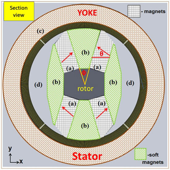
Figure 1.
The cross-section of a rotary cylindrical magnet. The red arrows are the directions of magnetization of permanent magnets.
Figure 1 shows the cross-section of the modeling cylindrical magnet in detail. In this figure, the light gray meshed regions (a) are Nd-Fe-B magnets; the light green hatched regions (b) are steel poles (made of steel AISI 1008); the light brown region (c) is the iron yoke (AISI 1008); the gray regions (d) are air; the dark gray area at the center is the shaft of the rotor made of non-magnetic steel; the black stripe set between the iron yoke and the steel pole is AMR materials. The dimension of the cylindrical magnet studied here is 291 mm in diameter and 10 cm in length in the axial direction to mimic the original design of T. Okamura et al. [12]. The rotating core consists of Nd-Fe-B (N52) magnets around the steel poles. The width of Nd-Fe-B is around 30 mm. The directions of the regenerator Gd plates are placed axially, and the gap between the iron yoke and the inner magnet is 15 mm. The magnetization directions of Nd-Fe-B magnets are indicated by red arrows in the figure. In Figure 1, the AMR material is separated into four parts, defined as Gdup, Gddown, Gdleft, and Gdright, around the circumference of the cylindrical magnet. In this configuration, when the Gdup and Gddown are magnetized, the Gdleft and Gdright are demagnetized. The cooling fluid (water) is flowing in the gap of Gd plates along the direction parallel to the axis of the cylindrical magnet. The rotation frequencies of the rotor we studied are 1–0.125 Hz, and the water flow direction is switched every 0.5–4 s. The rotation speed will affect the time to reach thermal equilibrium. However, it will not change the result of the magnetic duty cycle in this study. In the first half part of the cycle, the hot water flows in the gap of the Gd plates when the Gd is in the demagnetization stage, while the cold water flows into the gap during the magnetization at the other part of the cycle. A study of maximum magnetic field strength with the best magnetization time in a cycle is carried out to maximize the cooling power of this magnetic cooling system. As shown in Figure 1, the magnetization directions of Nd-Fe-B magnets are labeled by arrows. We define θ as the magnetization angle and ϕ as the pole face angle, which is the included angle of two surfaces of a pole face. In three-dimensional cylindrical geometries, the ϕ is the included angle between the two interface planes of Nd-Fe-B magnets and pole faces. A study of magnetic field strength as a function of magnetization angles, θ, and pole face angles, ϕ, is carried out in order to achieve the best magnetic field applied on the AMR material.
3. The Setting of Simulation
The numerical three-dimensional calculation of the magnetic field of the rotary magnet structure is carried out by the software COMSOL(version 4.4) [21]. In this calculation, the magnetic field distribution in each domain is determined by solving the Maxwell equations for the structure with proper magnetic properties. The operation point of Nd-Fe-B magnets is determined by a temperature-dependent load in the magnetic circuit. During the magnetic field analysis, the cylindrical magnet is placed in a three-dimensional air box. The boundary condition of this air box is to make the magnetic flux conservative. A typical calculating result based on the schematic configuration of Figure 1 is shown in Figure 2. Furthermore, the magnetic field distributions as functions of θ and ϕ are determined.
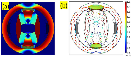
Figure 2.
The magnetic field distribution calculated by the COMSOL program on the schematic configuration in Figure 1. (a) magnetic field strength, and (b) magnetic field vector.
The thermal–hydraulic analysis of the system is also conducted using the COMSOL software. The geometry and heat transfer boundary conditions are illustrated in Figure 3. Figure 3a shows the simplified two-dimensional geometry considered in this study. The structure is axisymmetric, with the bottom boundary representing the centerline of the water channel. HHEX and CHEX refer to the heat exchangers on the hot and cold sides, respectively. Figure 3b,c show the geometries of the simplified 2-segment AMR along the flow direction and the simplified 3-segment AMR along the flow direction, respectively, employed in the thermal–hydraulic COMSOL simulation. This is a time-dependent analysis that involves the coupling of (1) the magnetocaloric effects in the AMR materials, (2) the heat transfer between the AMR materials and the water in the channel, (3) the flow of water in the channel, and (4) the heat transfer between the water in the channel and the heat exchangers. All steps of the AMR refrigeration cycle are simulated, and the thermodynamic performance is evaluated in terms of cooling capacity and the temperature span between two heat exchangers. The simulation process begins with the velocity profile of the water in the channel, followed by modeling the magnetization and demagnetization effects in the AMR materials. Next, the heat transfers between the AMR regenerator and the water in the channel, as well as the heat transfer between the water and the heat exchangers, are analyzed. Finally, the thermodynamic performance of the AMR refrigeration cycles is calculated. The velocity profile of the water in the channel is determined by solving the momentum and continuity equations for an incompressible fluid with constant properties. The volume of water flowing past the AMR regenerator during both the magnetization and demagnetization steps remains the same. Meanwhile, the temperature distribution in the channel is determined by solving the coupled heat transfer equations. For a detailed simulation process of the thermal–hydraulic analysis, please refer to the work of T. F. Petersen et al. [22]. Prior to the study of two- and three-segment graded AMR regenerators, the case of pure Gd AMR regenerators is investigated first. The simulated result is almost the same as our previously published work [6].
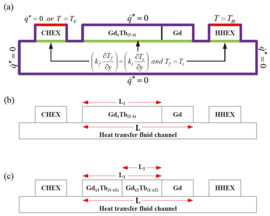
Figure 3.
(a) The heat transfer boundary conditions used in the thermal–hydraulic analysis of the magnetic refrigerator. There is no thermal flux at the purple boundary; the thermal flux and temperature are continuously smooth at the green boundaries. (b) The simplified 2-segment AMR along the flow direction; (c) The simplified 3-segment AMR along the flow direction employed in the COMSOL simulation.
4. Results and Discussion
4.1. Optimize the Magnetic Duty Cycle
Table 1 summarizes the results of the maximum magnetic field applied to the AMR materials and the magnetic duty cycles achieved. Here, the magnetic duty cycle is defined as the time interval that the magnetic field on AMR materials reaches 90% of the maximum magnetic field. The duty cycle is related to the pole face angle ϕ in Figure 1. At the beginning of the calculation, we keep the amount of Nd-Fe-B material fixed to find the maximum magnetic field as functions of ϕ and θ. A typical result of magnetic field strength under the configuration of Figure 1 is shown in Figure 4. In this figure, the magnetic field distribution in the middle of the gap is plotted out as functions of rotation angles around the circumference under four different ϕ angles at 37.8°, 52.2°, 64.8°, and 90° at θ = 45°. If the rotation speed is 1 Hz, the horizontal axis of Figure 4 rotates 360 degrees in 1 s. Figure 5 shows a summary of maximum magnetic fields as functions of θ under the fixed amount of Nd-Fe-B. The result indicates that for the magnet design with larger pole face angles, to achieve a higher magnetization strength, smaller magnetization angles are typically needed. However, with the fixed amount of Nd-Fe-B material, only when the magnet duty cycle is smaller than 20% can the maximum magnetic field be larger than 1 T. The magnetic field decreases significantly as the magnetic duty cycle approaches 50% (see Table 1). In order to increase the magnetization strength of AMR material as much as possible, more Nd-Fe-B is added with a sacrifice of the steel pole material, as shown in the schematic drawing in Figure 6, and the corresponding magnetic field is shown in Figure 7. Although the magnetic field in Figure 7 is stronger than the one in Figure 4 owing to the addition of 29% and more Nd-Fe-B materials, the maximum magnetic field decreases significantly as the duty cycle of magnetization increases. Figure 8 is a summary of the calculation result of the maximum magnetic field as a function of the magnetic duty cycles. In order to achieve the best 50% magnetic duty cycle to match the best thermo-hydraulic period, the maximum magnetic field is only 0.67 T, which gives rise to a serious reduction in the magnetic cooling capability.

Table 1.
The calculation of the maximum magnetic field on Gd, Bmax, and magnetic duty cycles at different configurations of magnetization angles, θ, and pole face angles, ϕ.
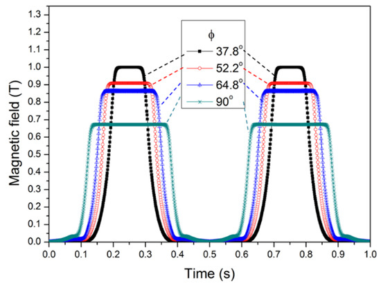
Figure 4.
The magnetic field distribution on Gd as a function of rotating time with the magnetization angle at θ = 45 degrees.
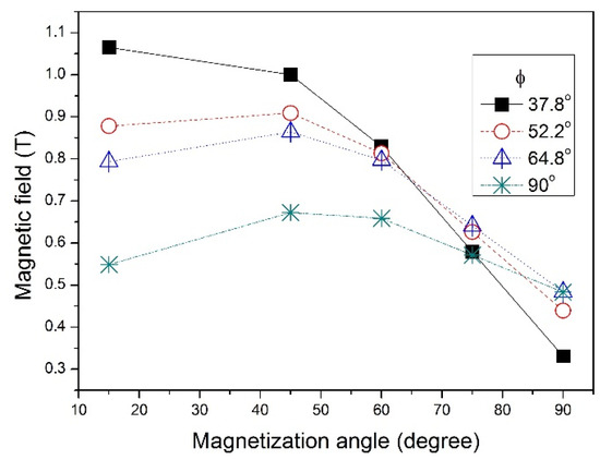
Figure 5.
The maximum magnetic field on Gd under four different pole face angles, ϕ, as functions of magnetization angles, θ.
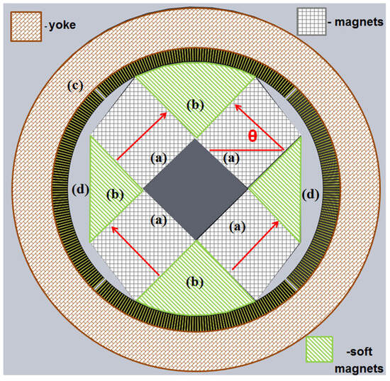
Figure 6.
The cross-section of a rotary-type cylindrical magnet with a pole face angle of 90 degrees and magnetization angle of 45 degrees. The amount of Nd-Fe-B immaterial used is increased significantly compared to Figure 1.
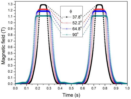
Figure 7.
The magnetic field distribution on Gd as a function of rotating time under four different pole face angles with a magnetization angle of 45 degrees is shown in Figure 6.
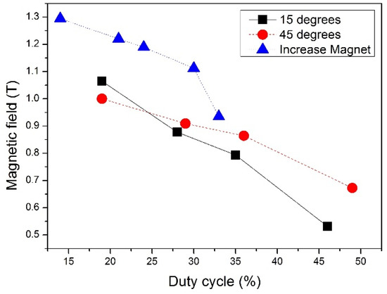
Figure 8.
The maximum magnetic field applied on Gd under different magnetic duty cycles operated at different magnetization angles of 15 degrees (black squares) and 45 degrees (red circles). The blue curve is the maximum magnetic field if more than 29% of the amount of Nd-Fe-B is used in the rotator (see Table 1).
By taking the highest magnetic field in each duty cycle as the input to do the thermo-hydraulic calculation, Figure 9 shows the average temperature on the cold side as time goes under different duty cycles of magnetization and demagnetization. It seems that the temperature on the cold side decreases faster when the duty cycle is around 21–36%. The cooling power obtained as a function of duty cycles is shown in Figure 10. In this thermo-hydraulic calculation, two cases with different temperatures (290 K and 293 K) at the cooling side (Tc in Figure 3b) are performed. In both cases, the initial system temperatures and the temperatures at the hot side (TH in Figure 3b) are kept at 298 K. In general, the cooling power increases as the temperature on the cooling side decreases. By selecting the highest cooling power and lowering the magnetic duty cycle for less magnetic materials needed, the best duty cycle is about 49% when the temperature on the cold side is at 293 K (with a temperature span of 5 K), while the best duty cycle is around 30% for the case of Tc = 290 K (with a temperature span of 8 K). The lower duty cycle can significantly reduce the amount of magnetic materials (Nd-Fe-B and Gd) to cut down the cost while still keeping the cooling power high.
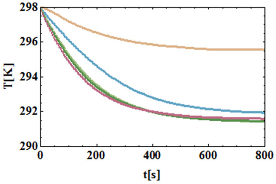
Figure 9.
A typical temperature change at the cold side as a function of time with hot ends at 298 K at the beginning and no thermal load at the boundary of the cold side. The duty cycles of magnetization-demagnetization are 15% (orange), 21% (red), 29% (green), 36% (light green), and 50% (blue), respectively.
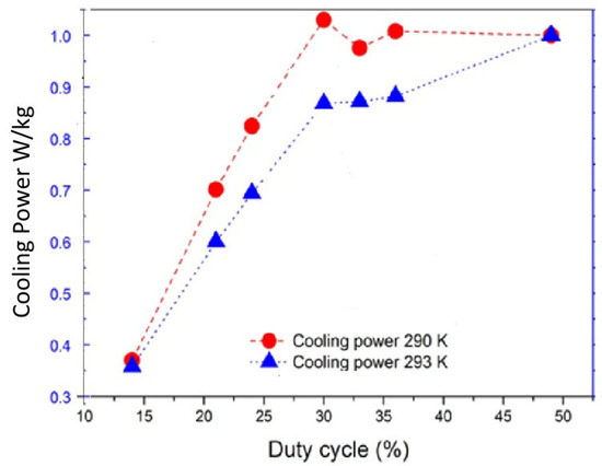
Figure 10.
The cooling power of a rotary magnetic refrigeration system with the 290 K (red circles) and 293 K (blue triangles) fixed at the cold end.
4.2. The Graded AMR Simulation
Figure 11 shows the simulated temperature variation in the cold heat exchanger over time for a fixed hot heat exchanger temperature of 298 K. At the beginning, the temperature variation rate of a pure Gd AMR regenerator is higher. The equilibrium cold heat-exchanger temperature of a pure Gd AMR regenerator is about 276.8 K. Meanwhile, the equilibrium cold heat-exchanger temperature of a two-segment Gd-Tb alloy AMR regenerator is found to be 4.6 K lower than that of the pure Gd regenerator. The cooling capacity (Qc) of the cold heat exchanger is employed to evaluate the performance of a regenerator. For two-segment AMR regenerators, x and r (=L2/L1) are used as the parameters to describe the composition and geometry of the AMR regenerators, and its cooling capacity (Qc2) is compared with that (Qc1) of a pure Gd regenerator (i.e., cooling capacity ratio = Qc2/Qc1). Figure 12 shows the relationship between the cooling capacity ratio (Qc2/Qc1) and composition (x), while cases with the same geometry (r) are grouped as curves. It is found that the cases of x are about 0.83, which results in Curie temperatures close to the cold heat-exchanger temperature, having the highest cooling capacity ratios. The decrease in Gd composition below 0.83 is unable to further increase the cooling capacity ratio. Figure 13 shows the relationship between the cooling capacity ratio and geometry, while cases with the same composition are grouped as curves. It is found that the cases of r about 0.6 have either the highest or the lowest cooling capacity ratios. In total, 26 cases of two-segment regenerators are simulated. All the resulting cooling capacity ratios are higher than 1, while the highest one is found to be 3.69 at r = 0.6 and x = 0.83. With the same length of 10 cm for both 2- and 3-segmented graded AMR materials along the flow direction, it is found that there is a 1.5~2 times increase in cooling capacity following the increase in segment number from 2 to 3. Meanwhile, the time required to reach the desired cold heat exchanger temperature decreases as the number of segments increases. Figure 14 compares the simulated temperature variation in two- and three-segment regenerators. Relatively, a three-segment AMR regenerator can cool a space faster, down to a lower temperature, and be more efficient than a two-segment one.
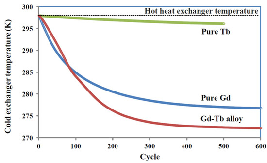
Figure 11.
Simulated temperature variations in the cold heat exchangers over cycles when AMR regenerators made of pure Gd, pure Tb, and Gd-Tb (1:1) alloy are used [6]. (Figure permission from IEEE).
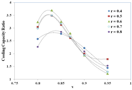
Figure 12.
Relationship between composition (x) and cooling capacity ratio of two-segment regenerators. Cases with the same geometry (r) are grouped as curves [6]. (Figure permission from IEEE).
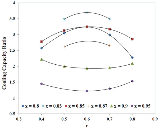
Figure 13.
Relationship between geometry (r) and the cooling capacity ratio of two-segment AMR regenerators. Cases with the same composition (x) are grouped as curves [6]. (Figure permission from IEEE).
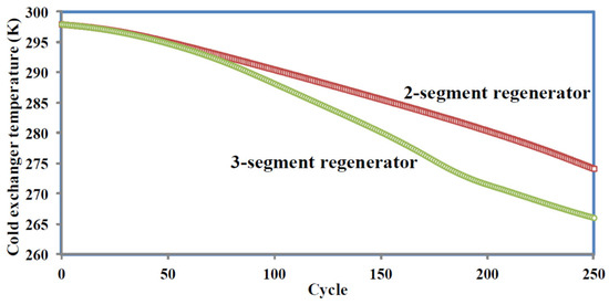
Figure 14.
Simulated temperature variations of the cold heat exchangers over cycles when two- and three-segment AMR regenerators of 10 cm in total length are used [6]. (Figure permission from IEEE).
5. Conclusions
A rotary cylindrical magnet was designed for magnetic refrigerators. For the rotary-type magnetic cooling system, the best duty cycle of this magnet should be 50% if the magnetic field can be kept at a high magnetic field at higher duty cycles. However, the calculation shows a serious reduction in the magnetic field strength at higher duty cycles. The optimized duty cycle of the cylindrical magnet design, which can reduce the amount of permanent magnet AMR materials, is around 30% for the temperature span of 8 K between hot and cold ends of a rotary-type magnetic cooling system after considering a thermos-hydraulic calculation.
Grading the AMR regenerator along the flow direction with multiple magnetocaloric materials improves the performance of magnetic refrigeration significantly. Compared to a pure Gd regenerator, it is demonstrated that a two-segment one can achieve more than a 3-time increase in cooling capacity. It has also been demonstrated that three-segment regenerators can cool a space faster, down to a lower temperature, and be more efficient than two-segment ones. By optimizing both the magnetic configuration in the cross-section view and along the axis direction, the highest cooling capacity for a two-pole rotary MR system can be achieved.
Author Contributions
Conceptualization, C.-H.L. and Y.-C.S.; methodology, K.-C.L.; software, P.-H.C. and C.-M.H.; validation, Y.-C.S., C.-H.L. and K.-C.L.; formal analysis; investigation, K.-C.L., C.-H.L. and Y.-C.S.; resources, K.-C.L.; data curation, P.-H.C. and C.-M.H.; writing—original draft preparation, P.-H.C. and C.-M.H.; writing—review and editing, C.-H.L.; supervision, K.-C.L., C.-H.L. and Y.-C.S.; funding acquisition, C.-H.L., K.-C.L. and Y.-C.S. All authors have read and agreed to the published version of the manuscript.
Funding
This project was supported by the National Science and Technology Council of Taiwan under contract number of NSC102-ET-E007-004-ET. The APC was supported by the C.-H.L. of National Tsing Hua University.
Institutional Review Board Statement
Not applicable.
Informed Consent Statement
Not applicable.
Data Availability Statement
Data are available upon request.
Acknowledgments
Ching-Chang Chieng initiated this magnetic refrigerator project, and part of the financial support from Delta Company (Taiwan) is acknowledged.
Conflicts of Interest
The authors declare no conflicts of interest.
References
- Bjork, R.; Bahl, C.R.H.; Smith, A.; Pryds, N. Review and comparison of magnet designs for magnetic refrigeration. Int. J. Refrig. 2010, 33, 437–448. [Google Scholar] [CrossRef]
- Alahmer, A.; Al-Amayreh, M.; Mostafa, A.O.; Al-Dabbas, M.; Rezk, H. Magnetic Refrigeration Design Technologies: State of the Art and General Perspectives. Energies 2021, 14, 4662–4687. [Google Scholar] [CrossRef]
- Bocanegra, J.A.; Scarpa, F.; Fanghella, P.; Marchitto, A.; Tagliafco, L.A. Optimization and development of a new rotary magnetic refrigerator. In Clean Technologies and Environmental Policy; Springer: Berlin/Heidelberg, Germany, 2024. [Google Scholar] [CrossRef]
- Zheng, Z.G.; Yu, H.Y.; Zhong, X.C.; Zeng, D.C.; Liu, Z.W. Design and Performance Study of the Active Magnetic Refrigerator for Room-Temperature Application. Int. J. Refrig. 2009, 32, 78–86. [Google Scholar] [CrossRef]
- Yu, B.F.; Gao, Q.; Zhang, B.; Meng, X.Z.; Chen, Z. Review on research of room temperature magnetic refrigeration. Int. J. Refrig. 2003, 26, 622–636. [Google Scholar] [CrossRef]
- Hsieh, C.M.; Su, Y.C.; Lee, C.H.; Cheng, P.H.; Leou, K.C. Modeling of graded active magnetic regenerator for room-temperature, energy-efficient refrigeration. IEEE Trans. Magn. 2014, 50, 4002904. [Google Scholar] [CrossRef]
- Ayas, A.O.; Akça, G.O.; Akyol, M.; Ekicibil, A. Magnetic refrigeration: Current progress in magnetocaloric properties of perovskite manganite materials. Mater. Today Comm. 2023, 35, 105988. [Google Scholar] [CrossRef]
- Yu, B.; Liu, M.; Egolf, P.W.; Kitanovski, A. A review of magnetic refrigerator and heat pump prototypes built before the year 2010. Int. J. Refrig. 2010, 33, 1029–1060. [Google Scholar] [CrossRef]
- Bahl, C.R.H.; Engelbrecht, K.; Bjork, R.; Eriksen, D.; Smith, A.; Pryds, N. Design concepts for a continuously rotating active magnetic regenerator. In Proceedings of the International Conference on Magnetic Refrigeration at Room Temperature, Baotou, China, 23–28 August 2010; pp. 1–7. [Google Scholar]
- Xia, D.; Xia, L. A novel permanent magnet system for magnetic refrigerator and its magnetic field analysis. In Proceedings of the International Conference on Electrical and Control Engineering, Wuhan, China, 25–27 June 2010; pp. 4928–4931. [Google Scholar]
- Bjork, R.; Bahl, C.R.H.; Smith, A.; Christensen, D.V.; Pryds, N. An optimized magnet for magnetic refrigeration. J. Magn. Magn. Mater. 2010, 322, 3324–3328. [Google Scholar] [CrossRef]
- Okamura, T. Improvement of 100 W Class Room Temperature Magnetic Refrigerator. In Proceedings of the 2nd International Conference on Magnetic Refrigeration at Room Temperature, Portoroz, Slovenia, 11–13 April 2007; pp. 377–382. [Google Scholar]
- Beltrán-López, J.F.; Palacios, E.; Velázquez, D.; Burriel, R. Design and optimization of a magnet for magnetocaloric refrigeration. J. Appl. Phys. 2019, 126, 164502. [Google Scholar] [CrossRef]
- Eriksen, D.; Engelbrecht, K.; Bahl, C.R.H.; Bjørk, R.; Nielsen, K.K.; Insinga, A.R.; Pryds, N. Design and experimental tests of a rotary active magnetic regenerator prototype. Int. J. Refrig. 2015, 58, 14–21. [Google Scholar] [CrossRef]
- Karpenkov, A.; Tukmakova, A.; Dunaeva, G.; Dergachev, P.; Karpenkov, D. Simulation of an operation of nested Halbach cylinder arrays in regenerative magnetic cooling cycles: The way to maximum thermal span. Int. J. Refrig. 2024, 168, 29–39. [Google Scholar] [CrossRef]
- Lee, C.H.; Cheng, P.H.; Leou, K.C.; Hsieh, C.M.; Su, Y.C. Study the Optimal Duty Cycle of a Coaxial Magnet for a Rotary Type Magnetic Refrigerator. In Proceedings of the Intermag 2023, Sendai, Japan, 15–19 May 2023. [Google Scholar] [CrossRef]
- Rowe, A.; Tura, A. Experimental investigation of a three-material layered active magnetic regenerator. Int. J. Refrig. 2006, 29, 1286–1293. [Google Scholar] [CrossRef]
- Nielsen, K.K.; Tusek, J.; Engelbrecht, K.; Schopfer, S.; Kitanovski, A.; Bahl, C.R.H.; Smith, A.; Pryds, N.; Poredos, A. Review on numerical modeling of active magnetic regenerators for room temperature applications. Int. J. Refrig. 2011, 34, 603–616. [Google Scholar] [CrossRef]
- Aprea, C.; Greco, A.; Maiorino, A. A numerical analysis of an active magnetic regenerative cascade system. Int. J. Energy Res. 2011, 35, 177–188. [Google Scholar] [CrossRef]
- Aprea, C.; Greco, A.; Maiorino, A. The use of the first and of the second order phase magnetic transition alloys for an AMR refrigerator at room temperature: A numerical analysis of the energy performances. Energy Convers. Manag. 2013, 70, 40–55. [Google Scholar] [CrossRef]
- COMSOL. A Multi-Physics Program, Version 4.4. Available online: https://www.comsol.com/ (accessed on 27 November 2013).
- Petersen, T.F.; Pryds, N.; Smith, A.; Hattel, J.; Schmidt, H.; Knudsen, H.-J.H. Two-dimensional mathematical model of a reciprocating room-temperature active magnetic regenerator. Int. J. Refrig. 2008, 31, 432–443. [Google Scholar] [CrossRef]
Disclaimer/Publisher’s Note: The statements, opinions and data contained in all publications are solely those of the individual author(s) and contributor(s) and not of MDPI and/or the editor(s). MDPI and/or the editor(s) disclaim responsibility for any injury to people or property resulting from any ideas, methods, instructions or products referred to in the content. |
© 2025 by the authors. Licensee MDPI, Basel, Switzerland. This article is an open access article distributed under the terms and conditions of the Creative Commons Attribution (CC BY) license (https://creativecommons.org/licenses/by/4.0/).