Abstract
Unidirectional pulsating heat pipes (PHPs) have been extensively investigated. However, a comprehensive understanding of the mechanism is still lacking. In this study, we analyze the unidirectional flow (distinct from thermosyphon) in closed PHP loops and reveal that the combined effect of the diameter variation and pressure distribution leads to a stable circulatory flow. Analogous to the Carnot thermodynamic cycle, a flow dynamical cycle along the loop is proposed to determine the highest momentum increment rate at the limit of the pressures and tube cross-sections. Furthermore, an effective pressure cycle considering friction resistance is introduced to elucidate the balance between fluid momentum increase and decrease. Experiments with glass PHP tubes are conducted to visualize fluid movements and characterize unidirectional flow PHPs accurately. The results confirm that varying-diameter PHP significantly promotes the circulatory flow, highlighting its potential for PHP development.
1. Introduction
Pulsating heat pipe (PHP) technology holds great promise in heat transfer due to its simple structure and excellent efficiency, particularly for electronic industries [1,2,3,4,5,6]. Compared to open-loop PHPs, closed-loop PHP (CLPHP) without end-striction exhibits superior performance [7]. Its high-frequency oscillation facilitates heat transportation from hot to cold ends. However, the oscillation model also inherently limits PHP advancement as it reduces the mean velocity through frequent alternations and shortens transport length due to the finite oscillation amplitude. Experimental results have already indicated that the thermal performance deteriorates with an increase in adiabatic length [8]. If CLPHPs work in a circulatory model, where all the vapor and liquid insides move clockwise or counterclockwise, it will allow a much longer distance between the cold and hot ends. Moreover, such circulatory flow with an intended direction provides more flexibility in design choices and even triggers the advancement of heat-driven micropumps [9,10].
To date, the circulatory flows have been observed experimentally and through simulations in closed loops. As the heat load increases and crosses a threshold, the oscillatory pattern will spontaneously transition into a circulatory flow [11,12,13,14]. However, this essentially represents a thermosiphon driven by buoyant differences in vertical tubes due to uneven vapor–liquid distribution [11,12,13,15]. As a prerequisite in thermosiphons, gravity directly determines the intensity of the circulatory flow [12,13,16]. In cases where the inclination angle is small or gravity is absent, the circulation flow will subside. Moreover, random vapor–liquid distribution fails to guarantee an intended flow direction and may contradict design requirements. To ensure desired flow directionality, check valves have been employed for controlling flow direction [17,18], while auxiliary heaters/coolers have been used to enhance the thermosiphon effect [19]. Notably, among these approaches are asymmetric PHPs with alternative diameter sizes that presented more efficient and gravity-insensitive circulatory flows [12,13,16,20,21,22,23,24,25,26]. This highlights the prospect of using asymmetric configuration to achieve asymmetric flow patterns. However, the underlying mechanism responsible for the unidirectional flows in asymmetric PHPs remains unclear. Some researchers attributed it to imbalanced capillary force and friction resistance [16,20]. However, a closer examination reveals that this is inadequate. Capillary forces exist on both the heating and cooling ends and somewhat counteract each other. Since surface tension weakens at high temperatures, circulatory flows should disappear at high heat transfer loads. However, experimental evidence contradicts this notion. The postulation that unbalanced friction resistance induces the unidirectional flow incorrectly suggests that circulatory flow is impossible for inviscid fluids. Kwon et al. propose that it is due to the asymmetric expansion of bubbles subjected to diverging tube walls, i.e., a bubble-based micropump [13,27]. However, a clear explanation still eludes us in understanding, designing, and optimizing circulating PHPs. Until now, the only confirmed conclusion is that unidirectional circulatory flow benefits from asymmetric configurations [24].
Aiming to elucidate the underlying mechanism of circulatory flow and optimize the design of CLPHPs, the Theoretical Analysis section develops a theory and investigates the combined impact of pressure distribution and cross-section variation on unidirectional flow. The Experiments and Results section validates the theoretical analysis and reveals some characteristics of unidirectional PHPs, especially the unexpected temperature elevation at cold turns. The Conclusions section summarizes the results and their possible value for future research.
2. Theoretical Analysis
2.1. Ideal Unidirectional Flow
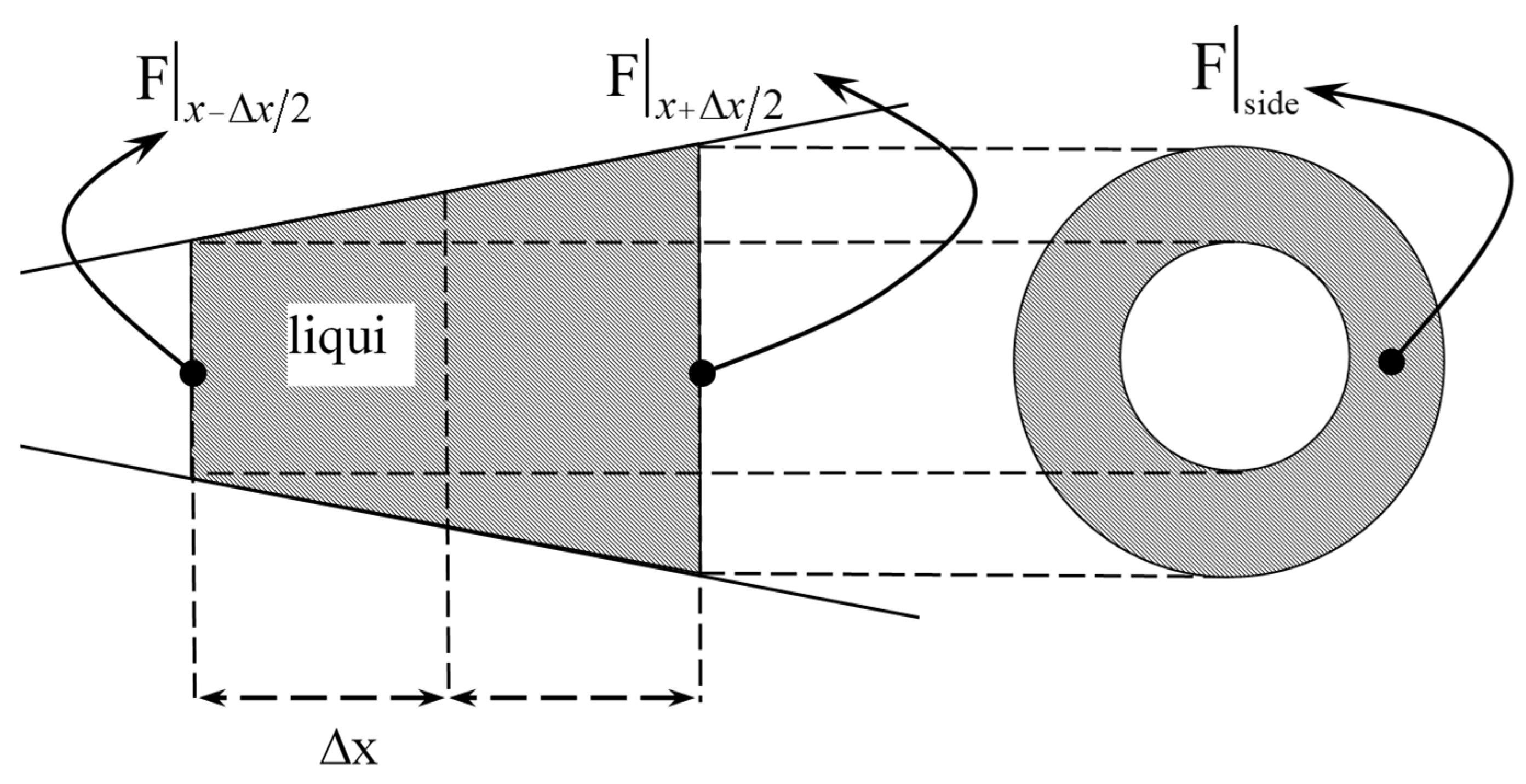
To elucidate the unidirectional flow mechanism, we shall begin by analyzing the net forces exerted by the pressure on the fluid along a loop. To simplify the analysis, an inviscid fluid segment is selected. As illustrated in Figure 1, the distance between two cross sections is denoted as Δx along the axial direction. Based on Talyor’s Therom, the forces on the two cross sections and the wall are thus expressed in terms of Δx as follows:
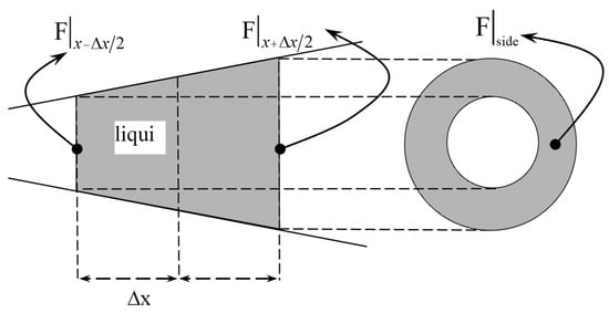
Figure 1.
Schematic of a fluid segment within a pipe.
According to Newton’s second law, the momentum change rate dI/dt of this segment can be expressed as.
where p and A present the pressure and cross-section area, respectively. As revealed in Equation (2), fluid acceleration occurs due to pressure reduction, with larger areas amplifying the acceleration effect. For a closed PHP, the fluid momentum change rate can be expressed as a closed curve integral:
According to Green’s Theorem, Equation (4) represents a rewritten form for the rate of momentum change (i.e., Equation (3)):
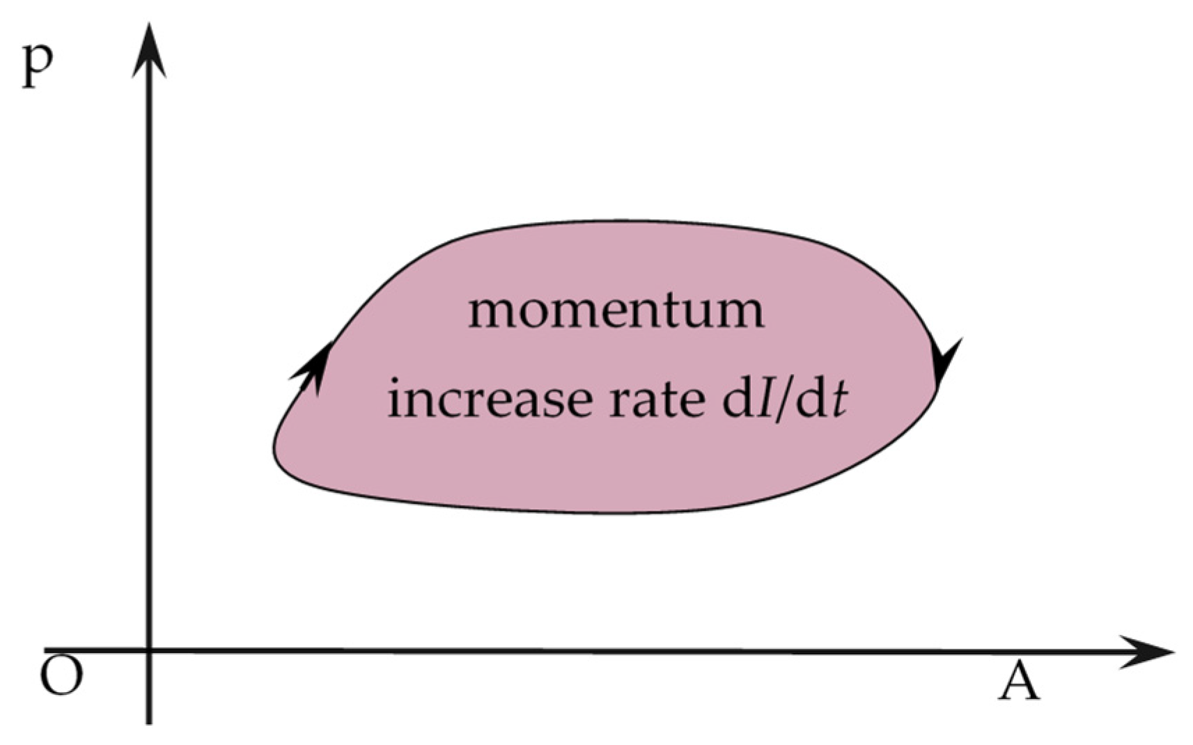
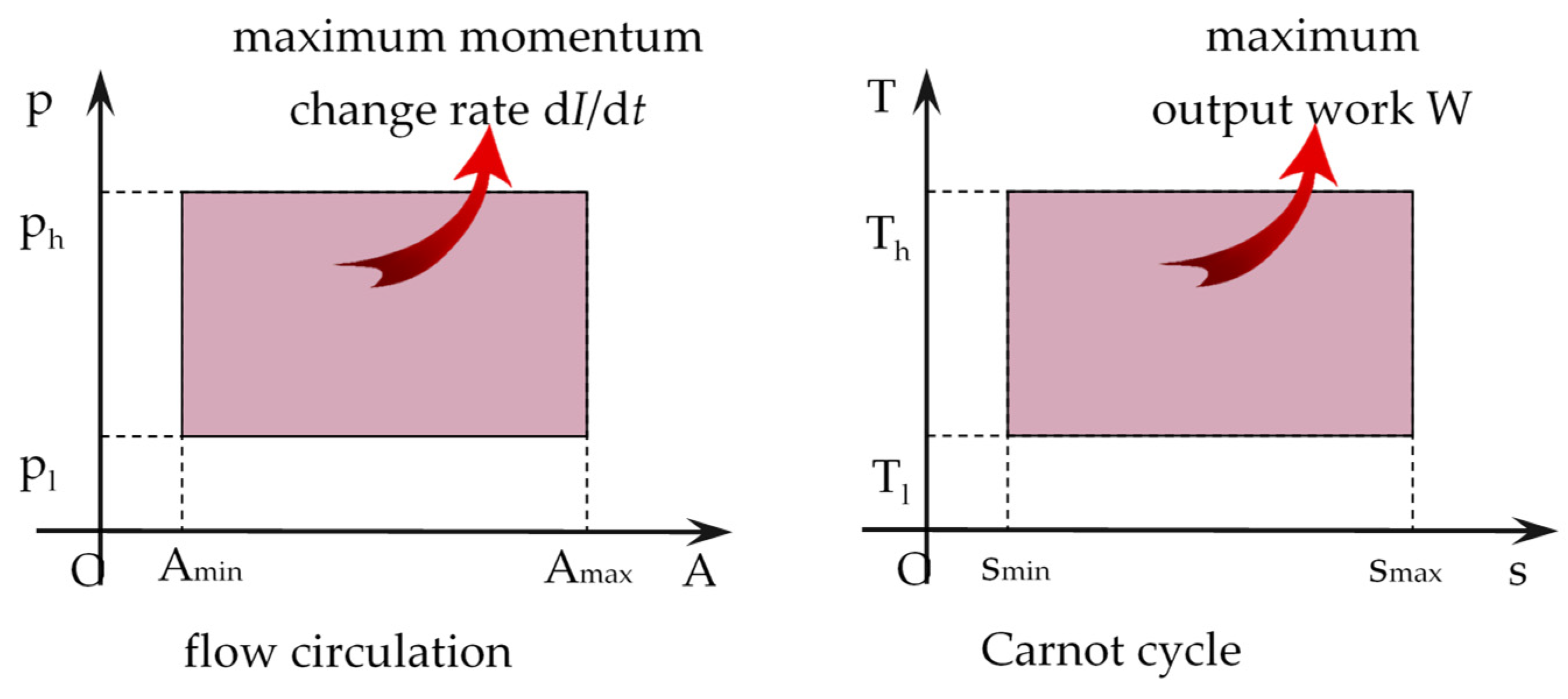
As of Equation (4), the unidirectional flow mechanism is revealed. Diameter variation and pressure distribution together incur a unidirectional circulatory flow within a closed loop. The driving force dI/dt—the rate of increase in momentum along the flow direction—can be expressed as the enclosed area in Figure 2 under consideration. The negative sign before the integral in Equation (4) indicates a clockwise path. In practical applications, the cross-sectional area of tube A is confined between Amax and Amin while the pressure p is constrained between pmax and pmin. Drawing an analogy with Carnot cycle’s maximum output work W in Figure 3, the maximum change rate of momentum dI/dt shall also fall within a rectangle area but bounded by the four lines A = Amin, A = Amax, p = pmin, and p = pmax.

Figure 2.
Momentum increment in a loop tube.

Figure 3.
Comparison between flow circulation and Carnot cycle.
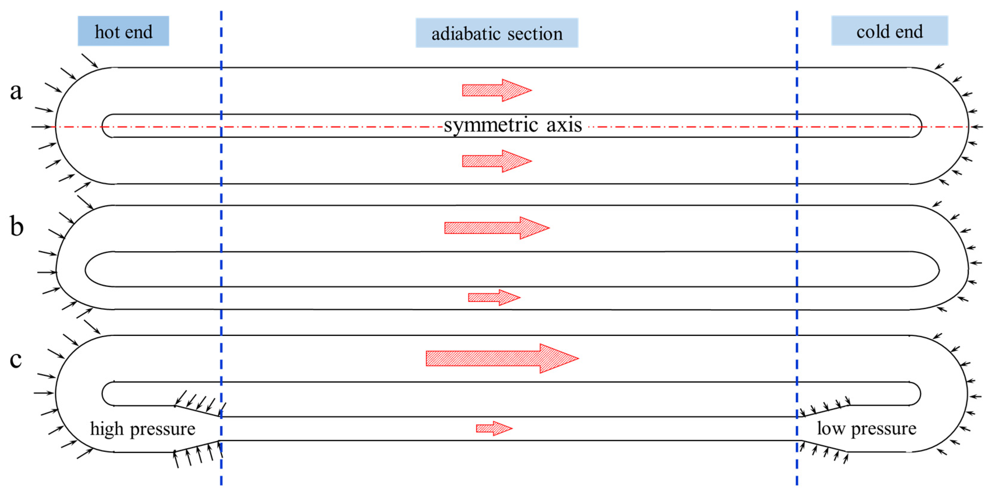
The following section will elucidate the mechanism from a physics perspective. As a kind of asymmetric flow, the unidirectional circulatory flow results from the asymmetric driving force, which is a combined result of tube–diameter variation and pressure distribution. In a uniform PHP (Figure 4a), the pressure profile exhibits high symmetry towards the mid-axis, with the fluid being pushed equally from the hot to the cold end. Consequently, there is no oriented flow there. Although, due to the random and uneven vapor–liquid distribution, expanding and shrinking bubbles can induce asymmetric movement of the liquid slugs, a steady unidirectional flow does not occur. Instead, a pulsating flow without directionality appears, characterized by a sequence of breakdown and reestablishment of uneven liquid–slug distribution. In contrast, the PHP of Figure 4b is composed of two tubes of different diameters. The equal pressure drop will push more fluid rightward in the larger tube and make a net clockwise flow, which was evident in other work [13]. However, it cannot achieve the highest driving efficiency for a circulatory flow because the heat source and sink in the same slender tube produce a reverse force against the clockwise flow. To minimize the counteractive force, both the heat source and sink should be excluded from the slender tube. Finally, a new design of unidirectional PHP comes to us, like in Figure 4c, in which two reducers connect the tubes of different diameters. Note that the pressure at the reducer wall has a tangent component in the flow direction. When the temperatures in these two reducers are different, the opposite tangent components cannot offset each other, and the residual component will drive the flow clockwise.
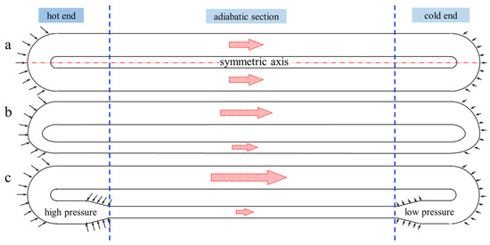
Figure 4.
Schematic of driving force for circulatory flow. ((a): constant-diameter PHP; (b): regular varying-diameter PHP; (c): redesigned varying-diameter PHP).
2.2. Two-Phase Effect
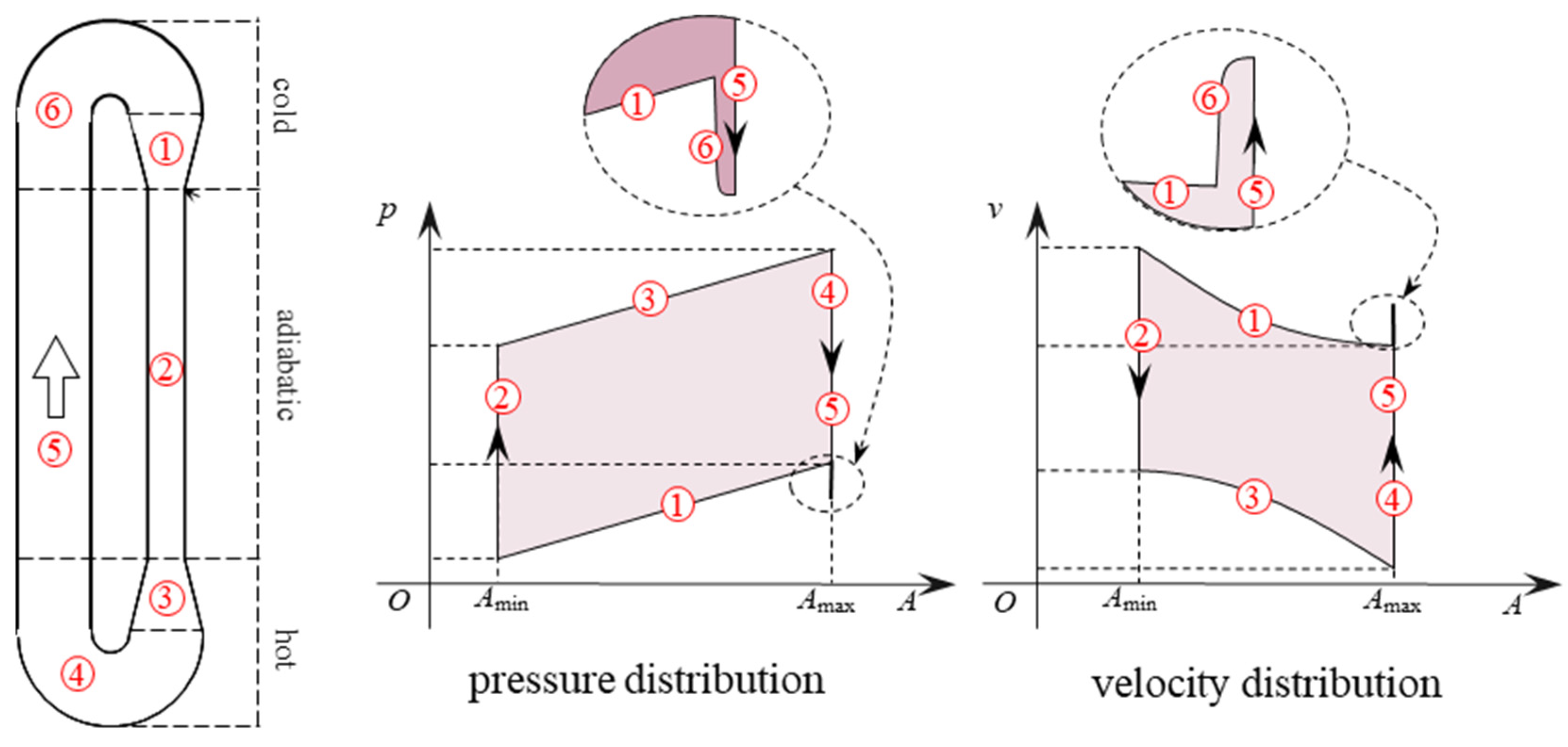
In PHPs, the alternate vapor–liquid distribution is important for the establishment and persistence of pressure difference but makes it impossible to maintain a steady pressure file, like in Figure 3. If a tube is filled only with pure vapor or liquid, the high pressure will be instantaneously transmitted to the other end at sound speed. As a result, the uniform pressure is established, causing no flow. In a partially charged PHP, expanding bubbles have to push the incompressible liquid slugs away rather than squeeze them smaller. Therefore, bubble expansion speed is limited by the high inertia of the liquid slugs, and so is the pressure transfer speed. Consequently, the pressure difference is established in PHPs. However, the significant property difference between moving liquid slugs/vapor plugs also causes periodical pressure fluctuation in the whole region. Since the pressure is almost uniform in vapor, pressure drop mainly appears in liquid. When the two reducers are occupied by vapor at the same time, the PHP circulatory flow achieves its highest efficiency like the first plot in Figure 3. At other times, the pressure file deviates from the ideal distribution. For a PHP of 50% v/v, each reducer is occupied by vapor at about half the time; although the vapor ratio is dependent on the local temperature and pressure. During the other 50% of the time, the reducer is occupied by liquid. Because of the small elasticity and large inertia, the liquid deceleration in the expander will increase the pressure. Similarly, the acceleration of the fluid in the reducer leads to a pressure drop. As a result, the enclosed area is no longer a rectangle but like Figure 5. Different from the pressure drop in sections 4 and 5, the vapor condensation and plug shrink in section 6 leads to a deceleration and pressure rise. To distinguish the change in section 6 from that in section 5, the route of section 6 is left-shifted a bit in the zoomed-in plots, although it theoretically overlaps with section 5. Consequently, the time-averaged pressure and velocity distribution should be like Figure 5, indicating that two-phase flow in a PHP cannot achieve the highest driving efficiency.
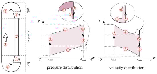
Figure 5.
Schematic of time-averaged pressure and velocity distribution inside a PHP.
2.3. Friction Effect
In reality, the driving force and resistance jointly determine the flow. When the resistance is subordinated to the driving force, the unidirectional flow will be enhanced and vice versa. For a steady unidirectional flow, the driving force will be perfectly balanced by frictional resistance. This study only targets a steady unidirectional flow in PHP. To be universal, the resistance is not specified in terms of dynamical properties or thermodynamical properties but is generalized as the drag force per unit length fres (see Figure 6). When analyzing a specific case, fres can be easily expressed with dynamical parameters. For a segment, the momentum change rate should be calculated as follows:
where peff is the effective pressure considering the resistance. The lower limit of the integral is an arbitrary reference point, which will not influence the results.
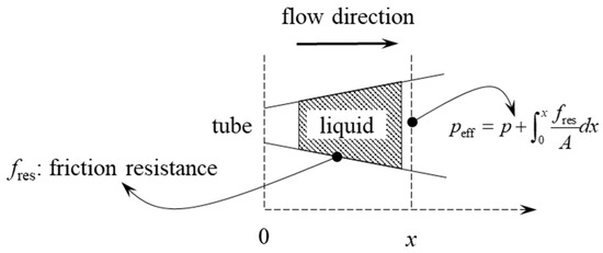
Figure 6.
Schematic of the effective pressure derivation.
Eventually, the flow cycle should be Figure 7 in an A-peff coordinate, considering the resistance effect. The cycle is composed of two smaller parts that are of the same area but go in opposite directions. The momentum gained in the clockwise cycle (shown in blue) is offset by the loss in the counterclockwise cycle (shown in yellow). The opposite directions of the two smaller cycles indicate the different changes of peff in the larger- and smaller-diameter tubes. The equal areas of the two smaller cycles indicate the net changes are equal in value in two tubes of different diameters. Because fres and A are always positive, ∂p/∂x has to be truly negative if ∂peff/∂x < 0. In the large-diameter tubes, the large cross-section makes a weak drag effect there. Also, the large cross-sectional area A itself reduces fres/A. The large saturation pressure drop between the two ends suffices to compensate for the relatively small fres/A, and ∂peff/∂x = ∂p/∂x + fres/A < 0, which leads to an accelerating flow. In the slender tube, the flow direction seems to be against the saturation pressure difference and there should be a deceleration. However, the effective pressure peff also decreases along the flow as in the large tube, which has been explained in the preceding. When the resistance results in a pressure drop along the flow, the vapor in the adiabatic slender tube will expand a little and thus cause an acceleration in the constant-diameter tube. Therefore, ∂peff/∂x = ∂p/∂x + fres/A < 0 in the slender tube, too. In section 6, the fluid is cooled and shrinks, thus there is a deceleration and pressure rise. In the A-peff coordinate, the rise of peff in section 6 overlaps with the reduction in section 5, so the peff rise in the zoomed-in plots is left-shifted a bit for clarity. In the expander and reducer, peff can either increase or decrease, depending on their radial heat transfer. At a low heat load, neither can fluid be well-heated in section 1 nor sufficiently cooled in section 3. The under-expanded fluid will decelerate in the divergent configuration and increase the effective pressure peff in section 3. Meanwhile, the under-shrunk fluid accelerates in the convergent configuration and thus may decrease peff in section 1. Oppositely, at a high heat load, fluid in sections 1 and 3 will be overly heated and cooled, respectively. The exceedingly expanded fluid can accelerate even in the divergent configuration and, thus, reduce peff in section 1. Meanwhile, the overly-shrunk fluid will decelerate even in the convergent configuration, and, thus, peff increases in section 1. As a result, peff variation in sections 1 and 3 changes with different heat loads as shown in Figure 7. Since a decrease in peff indicates an increase in velocity and vice versa. The velocity approaches its peak where peff is at its lowest. The A-peff coordinate, like Figure 7, should be helpful in unidirectional PHP design and optimization.
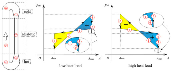
Figure 7.
Schematic of effective pressure distribution in a pulsating heat pipe.
Following is a more in-depth exploration of the resistance effect. Since we mainly focused on the axial flow rather than negligible radial flow in PHP, the momentum equation can be simplified into a one-dimensional form. Moreover, in a steady flow, all parameters are time-independent and their time partial derivatives are zero. Ultimately, the equation should be as follows:
Through mathematical treatment, it arrives at the following:
It indicates at a high velocity the same effective pressure drop can hardly increase the velocity any further. Therefore, peff drop should be assigned to the points where velocity is relatively slow. According to Fanning’s equation [28], the pressure drop is related to flow velocity and pipe diameter.
where λ is a dimensionless coefficient. In light of small Reynold numbers in PHPs, the pressure drop by resistance can be obtained as follows (i.e., Hagen–Poiseuille equation [29]):
where is the mass flow rate. At the same equal mass flow, the pressure drop is inversely proportional to the fourth power of the tube diameter. Thus, the expanding bubbles will push negligible fluid into the slender tube, which facilitates the startup of a unidirectional PHP. On the other hand, when a PHP approaches its stable state, the driving force is mostly counteracted in the slender tubes. Therefore, the slender tube should be shortened to reduce the resistance.
3. Experiments and Results
3.1. Experimental Visualization
To validate the aforementioned theoretical prediction, visualized experiments were conducted to investigate the flow characteristics within the PHPs. As shown in Figure 8, two distinct glass PHPs were fabricated for observation. One of them is of a constant-diameter of d = 2 mm, and the other exhibited varying diameters (d1 = 3 mm and d2 = 1 mm) with two reducers connecting the tubes. Before conducting the experiments, the tubes were filled with acetone 50% v/v. Each evaporation end was wrapped with an electrical resistance heating wire of identical length, whereas the opposite ends were covered by a cooling block through which water at a temperature of 20 °C circulated. The intermediate sections between the heating and cooling ends served as adiabatic regions; however, they remained exposed to air during the experiments to record the flow accurately. Each PHP was tested at 10 W, 20 W, 30 W, and 40 W with thermocouples employed for measuring the temperatures at its six designated points along its structure (see Figure 8). Additionally, high-speed imaging using a Phantom V2012 camera enabled recording the flows at a frame rate of 1000 fps. As there were no tracers seeded in the fluid, the leading edges of liquid slugs were chosen to manifest the flows, which was previously adopted in similar experimental studies [30]. Theoretically, the displacement of these leading edges was primarily attributed to both the motion of the liquid slug and the vapor condensation (or liquid vaporization). However, due to the significant density difference between liquid and vapor, any influence from condensation or vaporization on the leading edge movement was deemed negligible.
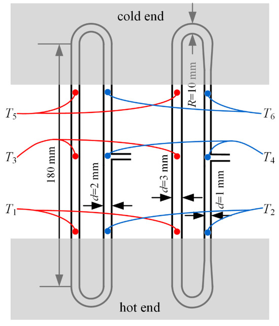
Figure 8.
Configurations of the tested PHPs.
3.2. Results and Analysis
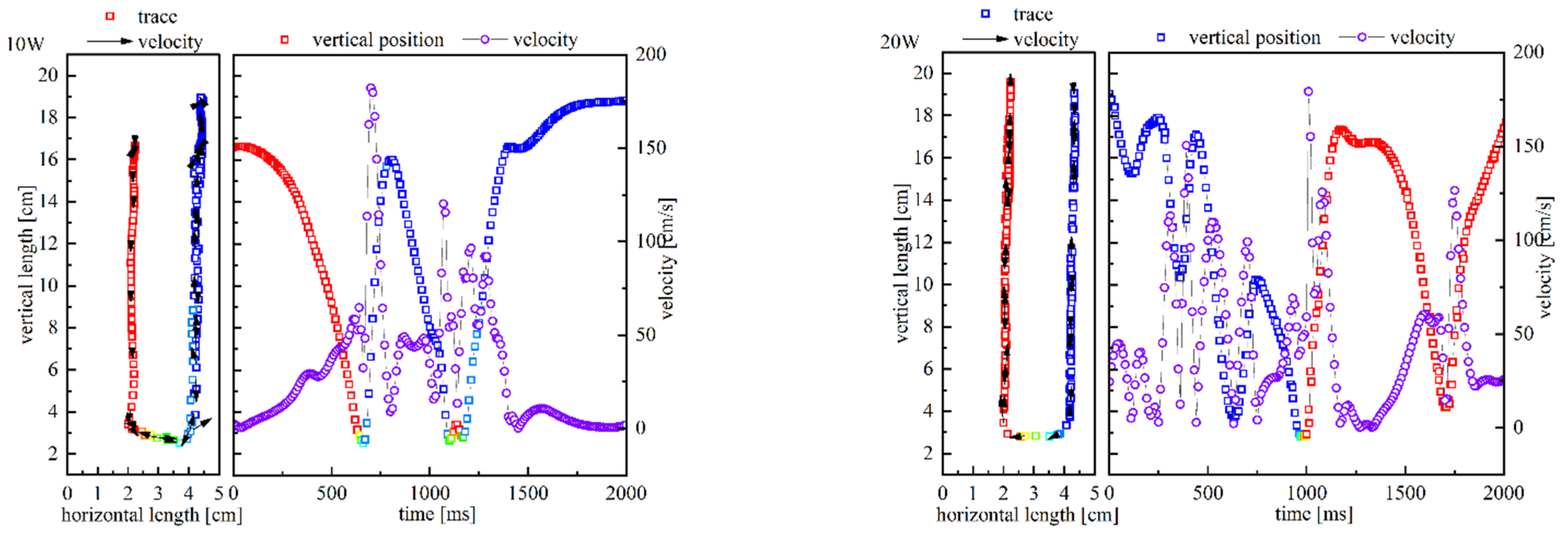
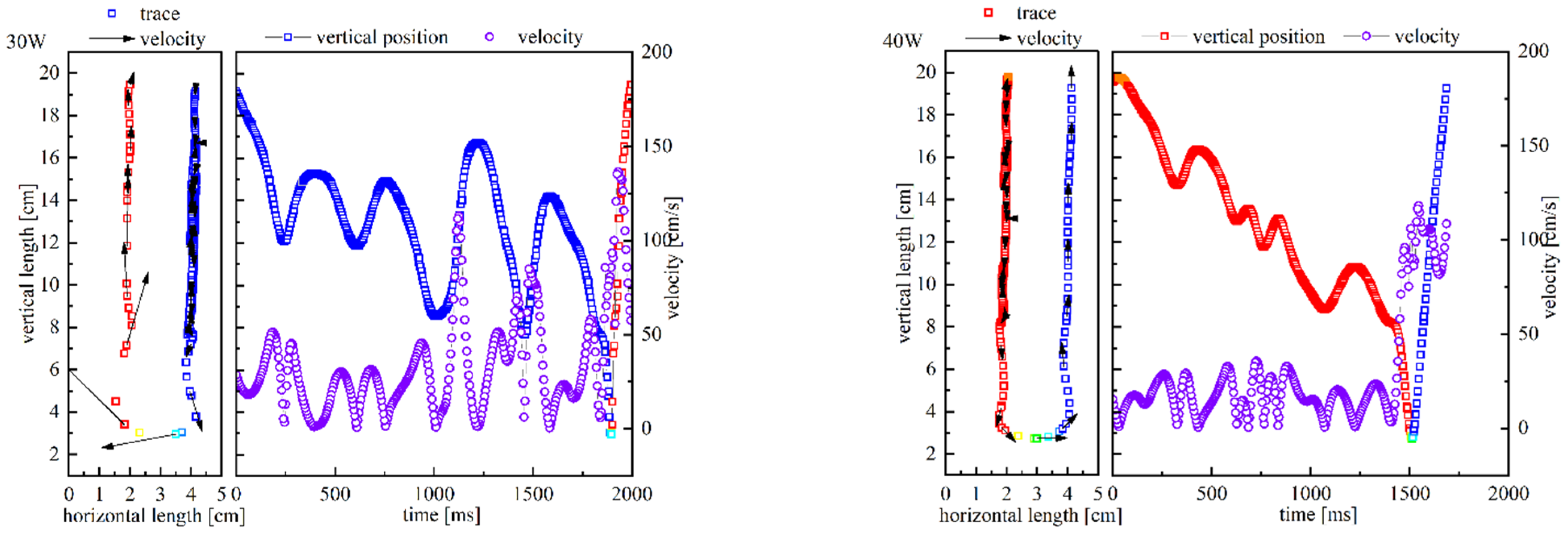
After the PHP stabilized, the positions of the leading edges were recorded and then fitted with the spline function to obtain their velocity except for the constant-diameter PHP at 30 W and 40 W. Figure 9 and Figure 10 present the positions and velocities of the leading edge. To differentiate between horizontal positions, different colors were used to mark their horizontal position values. In the case of the constant-diameter PHP, an oscillatory flow pattern superimposed on a slow circulation was observed, consistent with previous findings [15,31]. However, it should be noted that the direction of circulation appeared random as shown in Figure 9. The fluid exhibited counterclockwise circulation at 10 W and 40 W but clockwise circulation at 20 W and 30 W, indicating no preferred directionality. With increasing heat power input, both the circulation intensity and oscillation frequency increased; however, there was little change in the period of the circulation. Notably, attention should be drawn to the velocity distribution. There appeared a lower velocity when approaching the hot end but a higher velocity when leaving it. This phenomenon can be attributed to greater expansion necessitating a higher velocity of the upward fluid undergoing a longer heating process.


Figure 9.
Oscillatory flows at different heat loads.
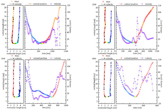
Figure 10.
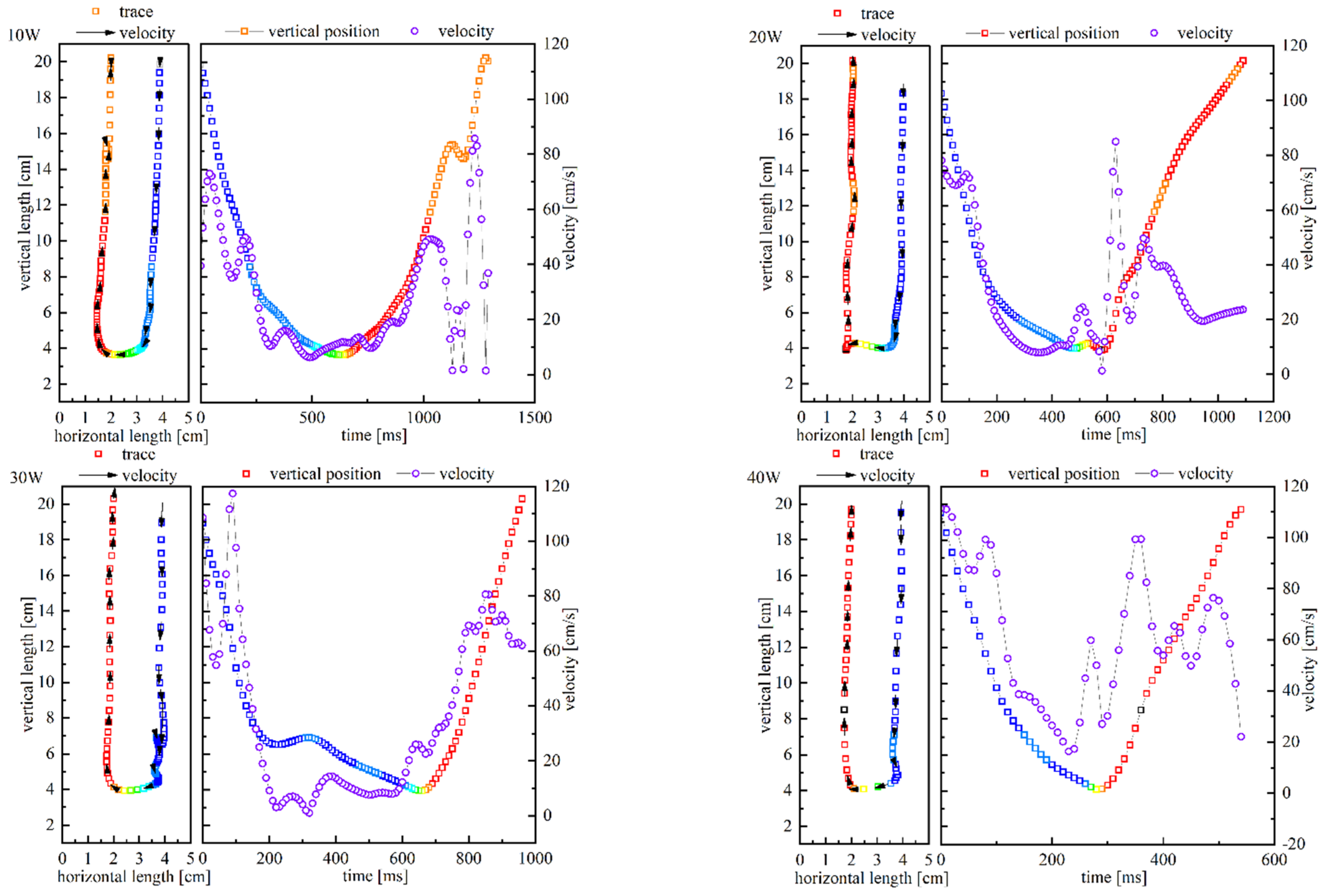
Circulatory flows at different heat loads.
The trace and velocity of the varying-diameter PHP are presented in Figure 10. All the flows at different heat inputs kept a clockwise circulation for a shorter period. As the heating power increased, the period decreased from 1.29 s at 10 W to 0.54 s at 40 W. In contrast to the constant-diameter PHP where the highest velocity was observed at the bottom, in the varying-diameter PHP, the velocity reached its minimum at the same location instead. Furthermore, unlike in the constant-diameter PHP where upward flow exhibited higher velocities than downward flow, in the varying-diameter PHP both directions showed comparable velocities. Compared with its constant-diameter counterpart, a more moderate transition between downward and upward flows was observed in the varying-diameter PHP, indicating a lower pressure at the hot turn region. Theoretically, this lower pressure could facilitate vaporization and radial heat transfer there, thereby enhancing overall heat transfer efficiency.
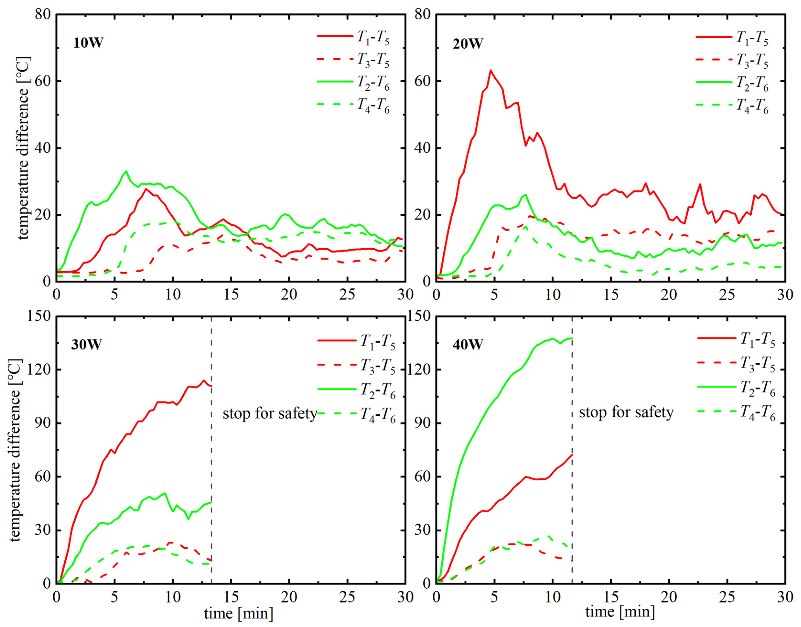
Below is the comparison of temperature distribution between two PHPs at 10~40 W. In Table 1, T1–T5, T2–T6, T3–T5, and T4–T6 are presented to compare heat transfer efficiency and analyze the characteristics of different heat transfer models. Figure 11 and Figure 12 illustrate the temperature variation respectively for the varying-diameter and constant-diameter PHPs. It was observed that the varying-diameter PHP reached a stable state in a shorter time: within one minute. Furthermore, it was found that, with an increase in heat load, the initiation time required became even shorter. In contrast, the constant-diameter PHP failed to stabilize within 100 s and lost its ability for efficient convective heat transfer at 30 W and 40 W, resulting in temperatures exceeding 100 °C. As a safety concern, the overtemperature led to tests being stopped at 80 s for 30 W and at 70 s for 40 W, respectively. In Table 1, T1–T5 and T2–T6 are relatively smaller in the cases of varying-diameter PHPs. The smaller vertical temperature difference indicated the higher heat transfer efficiency of the varying-diameter PHP. In the upward flow, T1–T5 was small, because the consistent direction of heat diffusion and fluid flow enhanced the heat transfer efficiency. In contrast, the heat diffusion was against the fluid flow in the downward flow. Therefore, the temperature difference T1–T5 was supposed much lower than T2–T6. However, compared with that of the constant-diameter PHP, T1–T5 was close to T2–T6 of the varying-diameter PHP. It demonstrated that the circulatory could reduce the difference in the temperature distribution between the two vertical tubes. More interestingly, unlike in a constant-diameter PHP, where T3–T5 > 0 and T4–T6 > 0, in the varying-diameter PHP these values are reversed (T3–T5 < 0 and T4–T6 < 0), revealing an unexpected reverse temperature gradient along heat transfer. Since there is no heat source in the adiabatic section, the temperature rise should be attributed to vapor compression. As it approached the top end, the decelerating flow increased pressure and subsequently temperature. Conversely, in the downward direction where the tube diameter changed from 3 mm to 1 mm causing acceleration, there was a decrease in both pressure and temperature. Ultimately, the fluid acceleration-deceleration-induced temperature crest at the cold turn contributed to an overall enhancement of heat transfer.

Table 1.
Temperature difference in vertical tubes when PHPs stabilized.
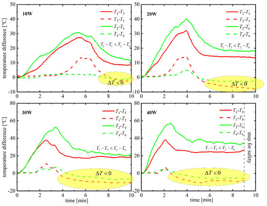
Figure 11.
Temperature distribution of the varying-diameter tube.
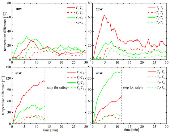
Figure 12.
Temperature distribution of the constant-diameter tube.
4. Conclusions
The impact of an asymmetric configuration was investigated both theoretically and experimentally for unidirectional flows in closed pulsating heat pipes, yielding the following conclusions:
① For inviscid fluids, the power driving a circulatory flow can reach its maximum when the pressure drops and increases respectively appear in the large and slender tubes, analogous to the Carnot cycle where heat is absorbed at the highest temperature and discharged at the lowest temperature. This ideal cycle can serve as a benchmark for the unidirectional driving power of real-world circulating PHPs, developing gravity-insensitive PHPs and improving their efficiency.
② The analysis result based on effective pressure distribution proved the effective pressure decreases by the same amount in different tubes when it reaches a steady state, revealing the common characteristics of circulating PHPs and helping design unidirectional PHPs.
③ The visual experiments confirmed the varying-diameter tubes can enable an intended circulating flow in a closed PHP, resulting in more efficient heat transfer than the constant-diameter configuration. PHPs of varying diameters exhibit a better prospect than conventional PHPs in high heat flux density heat transfer.
④ An unexpected temperature elevation appeared at the cold turn in a unidirectional PHP due to the fluid deceleration before and acceleration after the turn. This unexpected phenomenon can enhance the heat transfer on the cold ends of PHPs, improving their overall performance.
Author Contributions
Conceptualization, L.B.; Methodology, L.B.; Validation, Z.L. and S.W.; Investigation, L.B. and Z.L.; Writing—original draft, L.B.; Writing—review & editing, Y.J.; Supervision, Y.J. All authors have read and agreed to the published version of the manuscript.
Funding
This work was founded by the National Funded Postdoctoral Researchers Program (GZC20230341), the Fundamental Research Funds for the Central Universities (3132023527), the Ministry of Education Innovation Team Project (8091B042204), and the National Natural Science Foundation of China (52376046).
Data Availability Statement
The original contributions presented in this study are included in the article. Further inquiries can be directed to the corresponding author.
Conflicts of Interest
The authors declare no conflict of interest.
References
- Zhao, X.; Su, L.; Jiang, J.; Deng, W.; Zhao, D. A Review of Working Fluids and Flow State Effects on Thermal Performance of Micro-Channel Oscillating Heat Pipe for Aerospace Heat Dissipation. Aerospace 2023, 10, 179. [Google Scholar] [CrossRef]
- Priyadarsini, G.D.; Sankad, G. Microfluidic systems with a pulsating heat pipe. Phys. Fluids 2023, 35, 112001. [Google Scholar] [CrossRef]
- Kumar, A.; Singh, S. On the interaction between liquid slug and vapor bubble in the chaotic operation of pulsating heat pipe. Phys. Fluids 2023, 35, 054113. [Google Scholar] [CrossRef]
- Hota, S.K.; Lee, K.-L.; Leitherer, B.; Elias, G.; Hoeschele, G.; Rokkam, S. Pulsating heat pipe and embedded heat pipe heat spreaders for modular electronics cooling. Case Stud. Therm. Eng. 2023, 49, 103256. [Google Scholar] [CrossRef]
- Weng, Z.; Du, J.; Jiao, F.; Hong, Y.; He, Y.; Wang, C. Experimental investigation on the heat transfer performance of pulsating heat pipe with self-rewetting Fe3O4-nanofluid. Case Stud. Therm. Eng. 2024, 59, 104456. [Google Scholar] [CrossRef]
- Samana, T.; Kiatsiriroat, T.; Nuntaphan, A. Enhancement of fin efficiency of a solid wire fin by oscillating heat pipe under forced convection. Case Stud. Therm. Eng. 2014, 2, 36–41. [Google Scholar] [CrossRef]
- Bastakoti, D.; Zhang, H.; Li, D.; Cai, W.; Li, F. An overview on the developing trend of pulsating heat pipe and its performance. Appl. Therm. Eng. 2018, 141, 305–332. [Google Scholar] [CrossRef]
- Dilawar, M.; Pattamatta, A. A parametric study of oscillatory two-phase flows in a single turn Pulsating Heat Pipe using a non-isothermal vapor model. Appl. Therm. Eng. 2013, 51, 1328–1338. [Google Scholar] [CrossRef]
- Wang, Y.-N. Micropumps and biomedical applications—A review. Microelectron. Eng. 2018, 195, 121–138. [Google Scholar] [CrossRef]
- Luo, X.; Yang, L.; Cui, Y. Micropumps: Mechanisms, fabrication, and biomedical applications. Sens. Actuators A Phys. 2023, 363, 114732. [Google Scholar] [CrossRef]
- Khandekar, S.; Groll, M. An insight into thermo-hydrodynamic coupling in closed loop pulsating heat pipes. Int. J. Therm. Sci. 2004, 43, 13–20. [Google Scholar] [CrossRef]
- Tong, B.Y.; Wong, T.N.; Ooi, K.T. Closed-loop pulsating heat pipe. Appl. Therm. Eng. 2001, 21, 1845–1862. [Google Scholar] [CrossRef]
- Kwon, G.H.; Kim, S.J. Operational characteristics of pulsating heat pipes with a dual-diameter tube. Int. J. Heat Mass Transf. 2014, 75, 184–195. [Google Scholar] [CrossRef]
- Karthikeyan, V.K.; Khandekar, S.; Pillai, B.C.; Sharma, P.K. Infrared thermography of a pulsating heat pipe: Flow regimes and multiple steady states. Appl. Therm. Eng. 2014, 62, 470–480. [Google Scholar] [CrossRef]
- Zhang, Y.; Faghri, A. Advances and Unsolved Issues in Pulsating Heat Pipes. Heat Transf. Eng. 2008, 29, 20–44. [Google Scholar] [CrossRef]
- Chien, K.-H.; Lin, Y.-T.; Chen, Y.-R.; Yang, K.-S.; Wang, C.-C. A novel design of pulsating heat pipe with fewer turns applicable to all orientations. Int. J. Heat Mass Transf. 2012, 55, 5722–5728. [Google Scholar] [CrossRef]
- Thompson, S.M.; Ma, H.B.; Wilson, C. Investigation of a flat-plate oscillating heat pipe with Tesla-type check valves. Exp. Therm. Fluid Sci. 2011, 35, 1265–1273. [Google Scholar] [CrossRef]
- Feng, C.; Wan, Z.; Mo, H.; Tang, H.; Lu, L.; Tang, Y. Heat transfer characteristics of a novel closed-loop pulsating heat pipe with a check valve. Appl. Therm. Eng. 2018, 141, 558–564. [Google Scholar] [CrossRef]
- Abiev, R.S. Hydrodynamics and Heat Transfer of Circulating Two-Phase Taylor Flow in Microchannel Heat Pipe: Experimental Study and Mathematical Model. Ind. Eng. Chem. Res. 2020, 59, 3687–3701. [Google Scholar] [CrossRef]
- Kwon, G.H.; Kim, S.J. Experimental investigation on the thermal performance of a micro pulsating heat pipe with a dual-diameter channel. Int. J. Heat Mass Transf. 2015, 89, 817–828. [Google Scholar] [CrossRef]
- Liu, S.; Li, J.; Dong, X.; Chen, H. Experimental study of flow patterns and improved configurations for pulsating heat pipes. J. Therm. Sci. 2007, 16, 56–62. [Google Scholar] [CrossRef]
- Holley, B.; Faghri, A. Analysis of pulsating heat pipe with capillary wick and varying channel diameter. Int. J. Heat Mass Transf. 2005, 48, 2635–2651. [Google Scholar] [CrossRef]
- Tseng, C.-Y.; Yang, K.-S.; Chien, K.-H.; Jeng, M.-S.; Wang, C.-C. Investigation of the performance of pulsating heat pipe subject to uniform/alternating tube diameters. Exp. Therm. Fluid Sci. 2014, 54, 85–92. [Google Scholar] [CrossRef]
- Lim, J.; Kim, S.J. Effect of a channel layout on the thermal performance of a flat plate micro pulsating heat pipe under the local heating condition. Int. J. Heat Mass Transf. 2019, 137, 1232–1240. [Google Scholar] [CrossRef]
- Wang, J.; Pan, Y.; Liu, X. Investigation on start-up and thermal performance of the single-loop pulsating heat pipe with variable diameter. Int. J. Heat Mass Transf. 2021, 180, 121811. [Google Scholar] [CrossRef]
- Chen, X.; Li, H.; Han, X.; Liu, X. Thermo-hydrodynamic characteristics of a novel flat-plate micro pulsating heat pipe with asymmetric converging-diverging channels. Int. Commun. Heat Mass Transf. 2024, 152, 107282. [Google Scholar] [CrossRef]
- Geng, X.; Yuan, H.; Oguz, H.N.; Prosperetti, A. Bubble-based micropump for electrically conducting liquids. J. Micromech. Microeng. 2001, 11, 270–276. [Google Scholar] [CrossRef]
- Reay, D.A.; Kew, P.A.; McGlen, R.J. Chapter 2—Heat transfer and fluid flow theory. In Heat Pipes, 6th ed.; Reay, D.A., Kew, P.A., McGlen, R.J., Eds.; Butterworth-Heinemann: Oxford, UK, 2014; pp. 15–64. [Google Scholar] [CrossRef]
- Hagen-Poiseuille Equation—An Overview|ScienceDirect Topics. Available online: https://www.sciencedirect.com/topics/engineering/hagen-poiseuille-equation (accessed on 1 December 2024).
- Spinato, G.; Borhani, N.; Thome, J.R. Understanding the self-sustained oscillating two-phase flow motion in a closed loop pulsating heat pipe. Energy 2015, 90, 889–899. [Google Scholar] [CrossRef]
- Spinato, G.; Borhani, N.; d’Entremont, B.P.; Thome, J.R. Time-strip visualization and thermo-hydrodynamics in a Closed Loop Pulsating Heat Pipe. Appl. Therm. Eng. 2015, 78, 364–372. [Google Scholar] [CrossRef]


Disclaimer/Publisher’s Note: The statements, opinions and data contained in all publications are solely those of the individual author(s) and contributor(s) and not of MDPI and/or the editor(s). MDPI and/or the editor(s) disclaim responsibility for any injury to people or property resulting from any ideas, methods, instructions or products referred to in the content. |
© 2025 by the authors. Licensee MDPI, Basel, Switzerland. This article is an open access article distributed under the terms and conditions of the Creative Commons Attribution (CC BY) license (https://creativecommons.org/licenses/by/4.0/).