Article

A Double Resistive–Capacitive Approach for the Analysis of a Hybrid Battery–Ultracapacitor Integration Study

1
Faculty of Automotive and Construction Machinery Engineering, Institute of Vehicles and Construction Machinery Engineering, Warsaw University of Technology, Narbutta 84 Str., 02-524 Warsaw, Poland
2
Faculty of Mechatronics, Institute of Automatic Control and Robotics, Warsaw University of Technology, Sw. A. Boboli 8, 02-525 Warsaw, Poland
3
ETSEIB, ESAII, Universitat Politècnica de Catalunya, Av. Diagonal 647, 08028 Barcelona, Spain
4
Faculty of Electrical Engineering and Computer Science, Department of Cybernetics and Biomedical Engineering, VSB-Technical University of Ostrava, 708 00 Ostrava-Poruba, Czech Republic
*
Authors to whom correspondence should be addressed.
Energies 2025, 18(2), 251; https://doi.org/10.3390/en18020251
Submission received: 29 November 2024 / Revised: 2 January 2025 / Accepted: 7 January 2025 / Published: 8 January 2025

Abstract

:
The development of energy storage systems is significant for solving problems related to climate change. A hybrid energy storage system (HESS), combining batteries with ultracapacitors, may be a feasible way to improve the efficiency of electric vehicles and renewable energy applications. However, most existing research requires comprehensive modelling of HESS components under different operating conditions, hindering optimisation and real-world application. This study proposes a novel approach to analysing the set of differential equations of a substitute model of HESS and validates a model-based approach to investigate the performance of an HESS composed of a Valve-Regulated Lead Acid (VRLA) Absorbent Glass Mat (AGM) battery and a Maxwell ultracapacitor in a parallel configuration. Consequently, the set of differential equations describing the HESS dynamics is provided. The dynamics of this system are modelled with a double resistive–capacitive (2-RC) scheme using data from Hybrid Pulse Power Characterisation (HPPC) and pseudo-random cycles. Parameters are identified using the Levenberg–Marquardt algorithm. The model’s accuracy is analysed, estimated and verified using Mean Square Errors (MSEs) and Normalised Root Mean Square Errors (NRMSEs) in the range of a State of Charge (SoC) from 0.1 to 0.9. Limitations of the proposed models are also discussed. Finally, the main advantages of HESSs are highlighted in terms of energy and open-circuit voltage (OCV) characteristics.

1. Introduction

To combat climate change, 196 countries emitting 99.75% of the world’s greenhouse gases (such as carbon dioxide—CO2) signed the Paris Agreement on 4 November 2016 [1]. The signatories agreed to limit the global temperature increase to 1.5 °C and to reduce greenhouse gas emissions. The European Green Deal [2] aims to achieve these goals for net-zero greenhouse gas emissions by 2050. Transport is responsible for approximately 25% of the EU’s greenhouse gas emissions—71% of which are from road transport (Figure 1).
These goals can be achieved by developing sustainable and intelligent mobility solutions [3], such as deploying at least 30 million zero-emission electric vehicles in the EU by 2030. These vehicles will be supported by three million public charging points, including ultra-fast charging infrastructure compliant with the DC CHAdeMO 3.0 (ChaoJi) standard [4,5], delivering up to 900 kW of power according to IEC 61851-23:2014 [6] and the Alternative Fuels Infrastructure Regulation (AFIR) [7].
In addition to achieving climate neutrality, one of the most critical aspects of the targets is the sustainable development of renewable energy. The countries in the European Union have set specific targets for the overall share of renewable energy in final energy consumption, aiming to reach 32% by 2030 [8] or even up to 45% [9]. These targets include using renewable energy for heating, cooling, transport and electricity generation.
Additionally, EU regulations require member states to develop infrastructure and technologies to store heat and electricity simultaneously. This includes stabilising the power system [9]; promoting prosumer systems [10]; expanding alternative fuel infrastructure for vehicles, especially electric vehicles [7]; and integrating renewable energy sources into the primary power grid [9]. Given the limited predictability and daily variability of renewable energy production, sustainable development must prioritise the development of energy storage such as batteries (BESs) and ultracapacitors (UCs) [11]. These advances would increase the effective annual utilisation of renewable energy installations, thereby increasing the share of alternative, clean energy sources in the overall energy balance.
Electrochemical batteries [12] and ultracapacitors [13] are critical components in the charging stations developed by Gemamex Motion Co., with power ratings of up to 250 kW [14]. Moreover, they are integral to the drive systems of Chariot Motors’ battery electric buses [14] and ultracapacitor buses [15].
In addition, ultracapacitors and batteries are critical for starting large cogeneration systems based on internal combustion engines. Furthermore, ultracapacitors and batteries are used in Heavy-Duty Vehicles (HDVs), including those with conventional powertrains [16], such as trucks and all-electric vehicles [17,18,19,20,21,22,23,24,25,26,27,28].
When used under challenging conditions such as pulsed loads or low ambient temperatures, batteries experience significant performance degradation [29,30,31,32,33,34,35,36,37,38,39,40,41,42,43,44]. This includes increased internal resistance (especially electrolyte resistance), decreased electromotive force and reduced terminal voltage. Additionally, when starting internal combustion engines under these conditions, mechanical resistance increases due to the higher density of engine oil. These factors reduce the power and energy available from the battery, resulting in higher loads and a diminished service life [13].
Higher-capacity starter batteries are used to overcome these challenges and increase the specific energy density and power, or multiple batteries are often connected in parallel, increasing the cost. An alternative solution is a hybrid energy storage system (HESS) based on the parallel combination of an electrochemical battery and an ultracapacitor, whose equivalent circuit model is analysed in this paper.
Advances in electrochemical battery technology have significantly reduced the problems associated with starting internal combustion engines under standard operating conditions. Today’s starter batteries are affordable, efficient and relatively durable. However, high starting currents cause deep voltage drops at the battery terminals under challenging conditions, reducing starter performance and making it difficult to start internal combustion engines. Such conditions include low ambient temperatures, long periods of engine inactivity or high stationary battery loads, such as in vehicles with start–stop systems [22,23]. In start–stop systems, frequent engine starts and short battery charging periods accelerate battery discharge, reducing usable capacity and shortening battery life [22,23]. Other drawbacks include self-discharge and difficulty detecting impending battery discharge, often resulting in sudden, total discharge without warning [28,45,46,47,48,49,50,51,52,53,54,55,56,57,58,59,60,61,62]. These limitations can be mitigated by connecting a battery and an ultracapacitor in parallel, as described in Section 2.
Section 3 describes the test bench and details the employed load cycles, including the Hybrid Pulse Power Characterisation (HPPC) and a pseudo-random cycle. Section 4 introduces the equivalent circuit model for the battery–ultracapacitor system along with its mathematical representation. Section 5 explains the assumptions made for the parameter identification and error analysis, and Section 6 presents the model and experimental data results. The conclusions and recommendations are given in Section 7.

2. General Characteristics of HESSs Based on BES and UC Components

This section presents the open-circuit voltage (OCV) characteristics as a function of the State of Charge (SoC) for a battery (OCVBES), an ultracapacitor (OCVUC) and a hybrid energy storage system (HESS) based on the combination of a battery and ultracapacitor (OCVUC + BES). Additionally, energy characteristics for the battery (EBES), ultracapacitor (EUC) and HESS (EUC + BES) are also presented.

2.1. General Characteristics of BESs

The energy-versus-SoC plot for the example battery shown in Figure 2 has a flat, slightly sloping shape. This characteristic is advantageous, as it maximises the energy stored around the operating point. The energy stored in the battery can be defined as the integral of the OCVBES with respect to the stored charge Q. This is because Q is proportional to the SoC. Therefore, the energy stored in the battery can be expressed as follows:
E B E S = O C V d Q | S o C = Q Q n o m 1 d Q = Q n o m d S o C = Q n o m O C V d S o C
Since the OCV is nearly constant over the entire SoC range, the stored energy increases almost linearly with the increasing SoC. However, the slight variation in OCV with SoC means that even a small measurement error in the OCV can result in a significant error in SoC estimation (dOCV/dSoC ≈ 0 implies dSoC→∞). When estimating the OCV under load, the following relationship can be used:
O C V = U R i
It is important to note that SoC estimation errors are significant because dynamic processes such as voltage relaxation are not considered. More accurate methods, such as electrochemical impedance spectroscopy [63] and Kalman filtering [12,64,65], estimate the SoC by simultaneously measuring voltage and charge Q simultaneously, where Q is determined as the integral of the load current. Despite the superiority of adaptive methods in terms of better SoC estimation accuracy, they are not immune to error [66].

2.2. General Characteristics of UCs

As demonstrated in Figure 3, the energy stored in an ultracapacitor is equivalent to the integral of the OCV to the stored charge Q. Given that Q is proportional to the SoC and the OCV increases almost linearly with increases in the SoC, a quadratic function of the SoC approximates the stored energy. The stored energy equation therefore is given by
E U C = Q n o m O C V d S o C = Q n o m Q C 1 d S o C Q n o m C 1 S o C Q n o m d S o C = 1 2 S o C 2 Q n o m U n o m = 1 2 S o C 2 C U n o m 2
In contradistinction to batteries, ultracapacitors have the capacity to store energy even at low voltages (close to 0 V) [13,62]. Nevertheless, the total energy stored is less than that of batteries. The linear increase in the OCVUC with the SoC is advantageous for estimating the SoC and assessing the stored energy. In the simplest case, the SoC of an ultracapacitor can be evaluated by measuring the OCV and using the function OCV = f(SoC), as demonstrated in Figure 3. It should be noted that the OCV varies significantly with the SoC; even substantial OCV measurement errors will result in minimal SoC estimation errors, expressed as follows:
d O C V / d S o C U n o m d O C V   U n o m d S o C
As with batteries, the OCVUC of an ultracapacitor under load can be estimated using Equation (4). However, significant SoC estimation errors remain significant due to dynamic processes such as voltage relaxation. To achieve more accurate SoC estimation, even under load, the utilisation of tools such as Kalman filters [12,67,68,69,70] or predictive methods [71,72] based on recursive neural networks [39,40,73,74] is recommended.

2.3. HESSs Based on BESs and UCs

The characteristics of ultracapacitors and batteries are often complementary, especially when connected in parallel, thus creating a system that takes advantage of both energy storage solutions (see Figure 4a). A parallel configuration of ultracapacitors allows the system to simultaneously achieve both high energy density (battery effect) and high power density (ultracapacitor effect) [75,76]. This configuration maintains performance even at low ambient temperatures (ultracapacitor effect) and low SoC levels, as discussed in [12,13,21,77]. The relationship between the energy stored in the battery (EBES), the ultracapacitor (EUC) and the HESS (EUC+BES) as a function of voltage is presented in Figure 4a.
These graphs demonstrate the advantages of combining these components in parallel. On the one hand, the system provides substantial energy in the higher voltage range (supplied by the battery). At the same time, it retains the ability to store energy at lower voltages (ultracapacitor effect). With an acceptable large ultracapacitor capacity, the stored energy may be sufficient to start an internal combustion engine (ICE) [75], even when the battery is discharged (i.e., at very low system voltages). Battery discharge can occur due to low ambient temperatures or high currents from electrical equipment onboard.
As illustrated in Figure 4b, the OCVUC+BES of the ultracapacitor–battery system exhibits a substantial curvature for SoC < 0.2, indicating a notable relationship between the two parameters. A low SoC is the cause of a more intense battery OCV drop. This behaviour enables earlier detection of an approaching SoC = 0, reducing the risk of sudden power unavailability and improving system reliability.

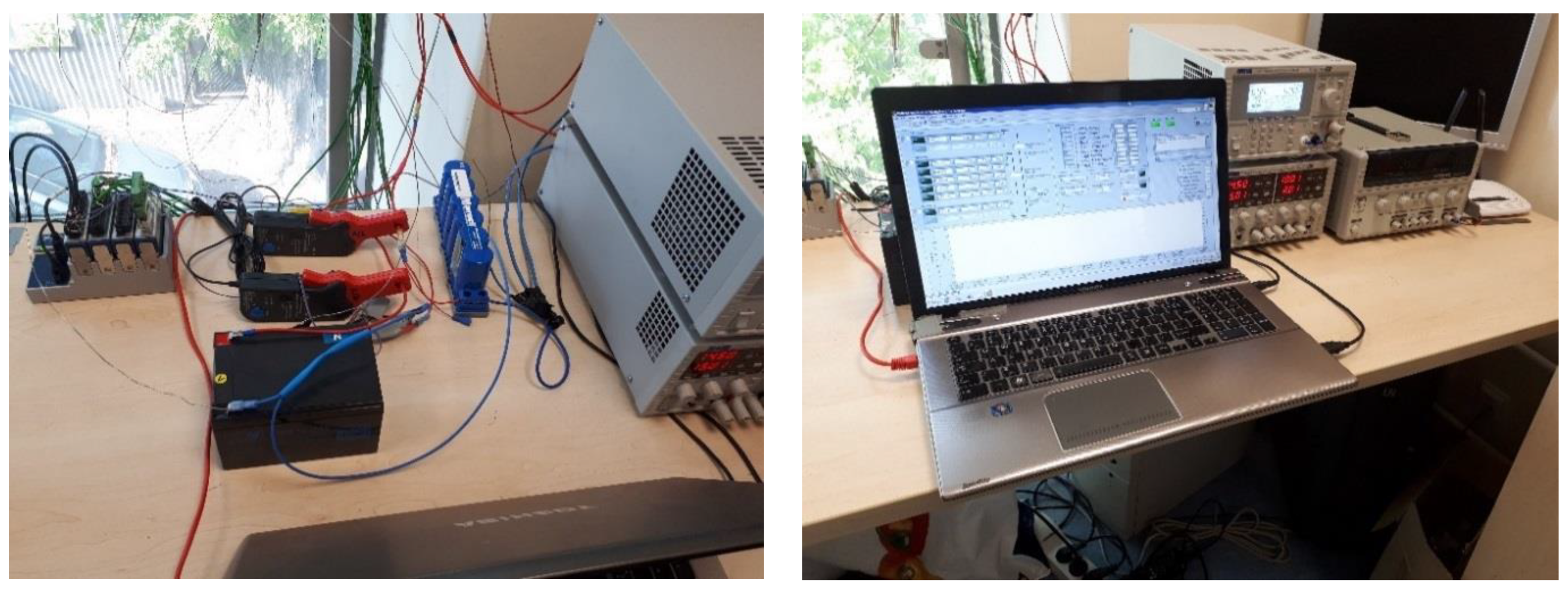
3. Description of the Test Stand

A special test bench was developed to test the battery and the ultracapacitor. The technical specifications of the battery and ultracapacitor are presented in Table 1.
The selected components are reference objects for 6 V low-voltage installation tests. The measurement track included the following components:
  • PC with LabVIEW 2018 software: Used to develop an application for recording selected experimental data. The application cooperated with National Instruments measurement modules:
    • NI 9206: Voltage acquisition at battery terminals.
    • NI 9213: Temperature measurement at terminals, battery housing and ambient temperature using K-type thermocouples.
    • NI 9401: TTL digital I/O module for controlling relays in charge and load (discharge) circuits.
  • TA018 PICO current clamps: Acquired current values for both components.
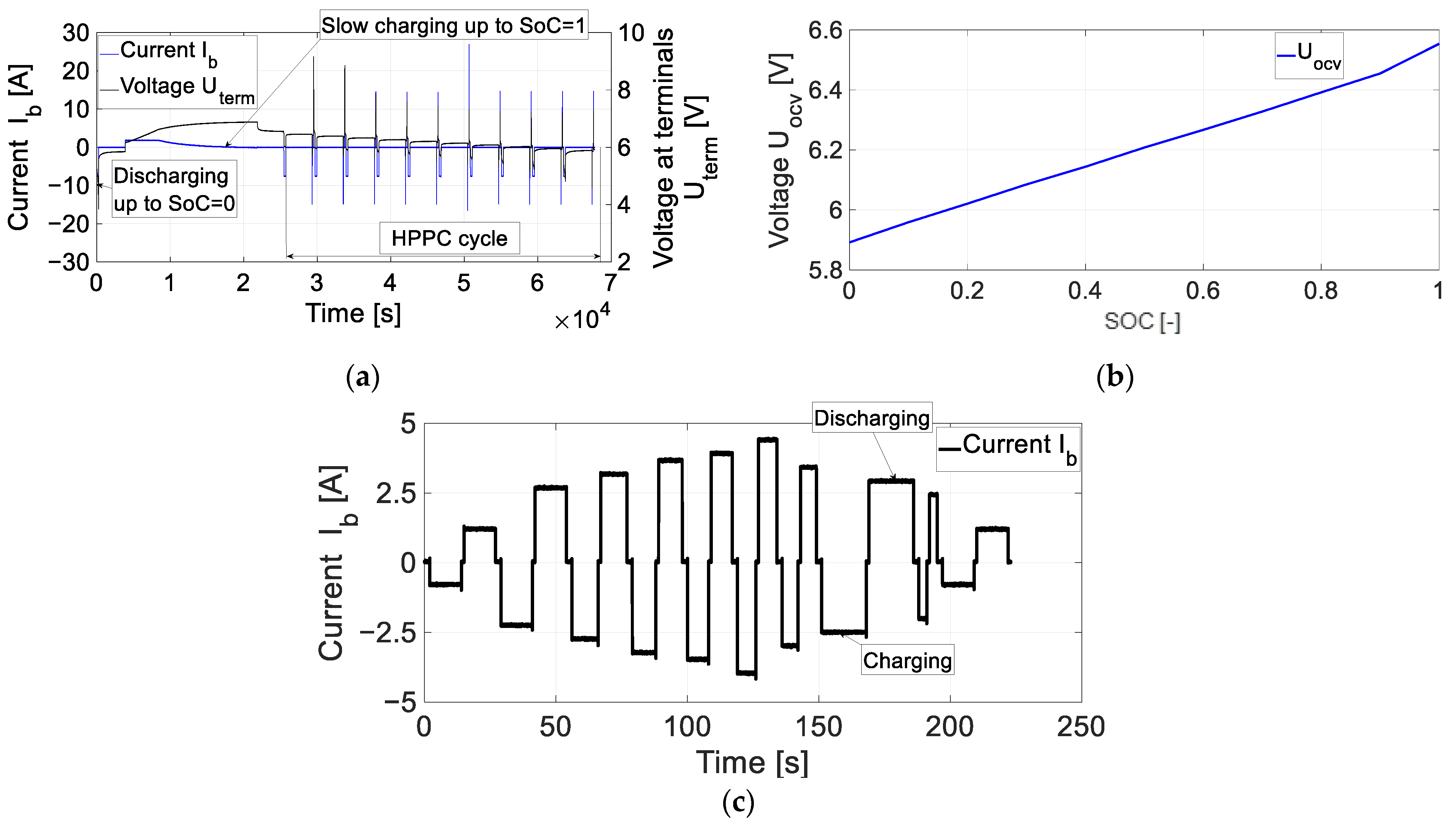
The test stand (Figure 5) allowed for the programming of charge and discharge cycles for the energy storage components. Charge and load current values were controlled via an Ethernet connection to a programmable power supply (TTI CPX400DP) and programmable load (TTI LD400P).
The measurement track was protected from damage by pre-set current and temperature limits. If these limits were exceeded, the system automatically disconnected components to prevent damage, especially during long-term operational testing. In addition, a notification system kept the user informed via a TCP/IP network (e.g., a “warning status” when temperature or current thresholds were exceeded), and the programme had reporting capabilities for mobile devices.
The battery and the ultracapacitor (Figure 5) were connected in a passive topology, i.e., physically connected in parallel.

Adopted Load Cycles

The Hybrid Pulse Power Characterisation (HPPC) cycle was performed at the beginning of the study (Figure 6a). The open-circuit voltage (OCV) was determined from the HPPC cycle, as shown in Figure 6b. The Uocv value ranged from 5.89 V (SoC = 0) to 6.55 V (SoC = 1).
A pseudo-random cycle (Figure 6c) was designed to run the experiment at constant values of SoC = const., transitioning from full battery charge (SoC = 1) to full battery discharge (SoC = 0) in steps of dSoC = 10%. However, due to strongly nonlinear processes at SoC = 1 (instantaneous overload) and SoC = 0 (total discharge), these limits were excluded when identifying the battery parameters.

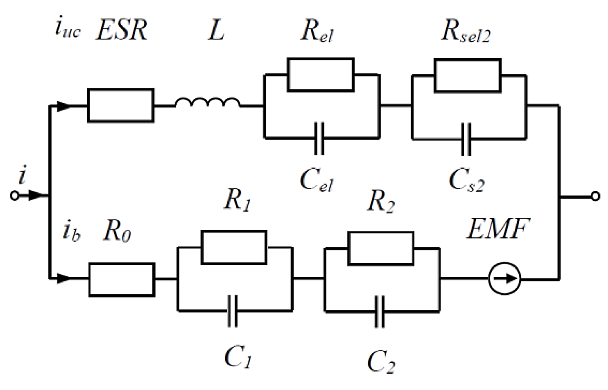
4. Mathematical Models of the BES-UC System Based on a Replacement Double RC Loop Diagram

This section presents an equivalent circuit of the battery–ultracapacitor module, using a passive parallel connection between the battery and the ultracapacitor (Figure 7). The equivalent diagram of the battery–ultracapacitor module can be divided into two parts: the first, through which the current iuc flows—this part is related to the ultracapacitor—and the second, through which the current ib flows—this part is related to the battery.
Based on the analysis of the current distribution and according to Kirchhoff’s first law, it can be written for Figure 7 as follows:
i = i b + i u c i b = i i u c
Respectively, the voltage changes for the battery and the ultracapacitor can be written as a system of equations:
u = U t = U O C V U 1 U 2 U 0 u = u c u L u E S R = u c L d i u c d t i u c E S R
In Equation (6), the voltages U1, U2 and U0 are unknown. They can be determined from the following system of equations:
U ˙ 1 = R 1 C 1 1 U 1 + C 1 1 I b U 1 = R 1 C 1 C 1 1 I b U ˙ 1 U ˙ 2 = R 2 C 2 1 U 2 + C 2 1 I b U 2 = R 2 C 2 C 2 1 I b U ˙ 2 0 = R 0 1 U 0 + I b U 0 = I b R 0
Another unknown parameter in dependency (7) is the voltage, uc, which can be calculated based on the diagram analysis from Figure 7:
u c = u c 1 + u c 2 u ˙ c 1 = R 1 C 1 u c 1 u c 1 + C 1 u c 1 i u c u c 1 = R 1 C 1 u c C 1 u c 1 i u c u ˙ c 1 u ˙ c 2 = R 2 C 2 u c 1 u c 2 + C 2 u c 1 i u c u c 2 = R 2 C 2 u c C 2 u c 1 i u c u ˙ c 2
We know that for the ultracapacitor, the relationship between current iuc and voltage uc can be written as
i u c = C d u c d t = C 1 u c d u c 1 d t + C 2 u c d u c 2 d t = C 1 u c u ˙ c 1 + C 2 u c u ˙ c 2
Inserting Equation (5) into Equation (6) results in
u R 1 i u c R 2 C 2 C 1 i u c R 0 i u c = U O C V R 1 i + R 1 C 1 u ˙ 1 R 2 C 2 C 1 i + R 2 C 2 u ˙ 2 R 0 i
By inserting u1c and uc2 from Equation (8) into Equation (6), we obtain
u = u c 1 + u c 2 u L u E S R = u c L d i u c d t i u c E S R = R 1 C 1 u c C 1 u c 1 i u c u ˙ c 1 + R 2 C 2 u c C 2 u c 1 i u c u ˙ c 2 L d i u c d t i u c E S R
Replacing iuc in Equation (12) gives
u = R 1 C 1 u c C 1 u c 1 C 1 u c u ˙ c 1 + C 2 u c u ˙ c 2 u ˙ c 1 + R 2 C 2 u c C 2 u c 1 C 1 u c u ˙ c 1 + C 2 u c u ˙ c 2 u ˙ c 2 + L C 1 u c u ¨ c 1 + C 2 u c u ¨ c 2 C 1 u c u ˙ c 1 + C 2 u c u ˙ c 2 E S R
Solving Equation (10) with Equation (12), we obtain the final form of the relationship in the battery–ultracapacitor module with two RC loops:
U O C V R 1 i + R 1 i u c + R 1 C 1 u ˙ 1 R 2 C 2 C 1 i + R 2 C 2 C 1 i u c + R 2 C 2 u ˙ 2 R 0 i + R 0 i u c = u + L C 1 u c u ¨ c 1 + C 2 u c u ¨ c 2 + C 1 u c u ˙ c 1 + C 2 u c u ˙ c 2 E S R + R 1 C 1 u c C 1 u c 1 C 1 u c u ˙ c 1 + C 2 u c u ˙ c 2 u ˙ c 1 R 2 C 2 u c C 2 u c 1 C 1 u c u ˙ c 1 + C 2 u c u ˙ c 2 u ˙ c 2
Reordering relationship (13), we obtain
U O C V R 1 + C 1 1 C 2 R 2 R 0   i + R 1 C 1 u ˙ 1 + R 2 C 2 u ˙ 2 = u + R 1 + C 2 1 C 1 R 2 + R 0   i u c + L C 1 u c u ¨ c 1 + C 2 u c u ¨ c 2 + E S R C 1 u c u ˙ c 1 + C 2 u c u ˙ c 2
Equations (5)–(14) were implemented in MATLAB and Simulink programmes to identify the parameters of the battery–ultracapacitor module model in Section 5.

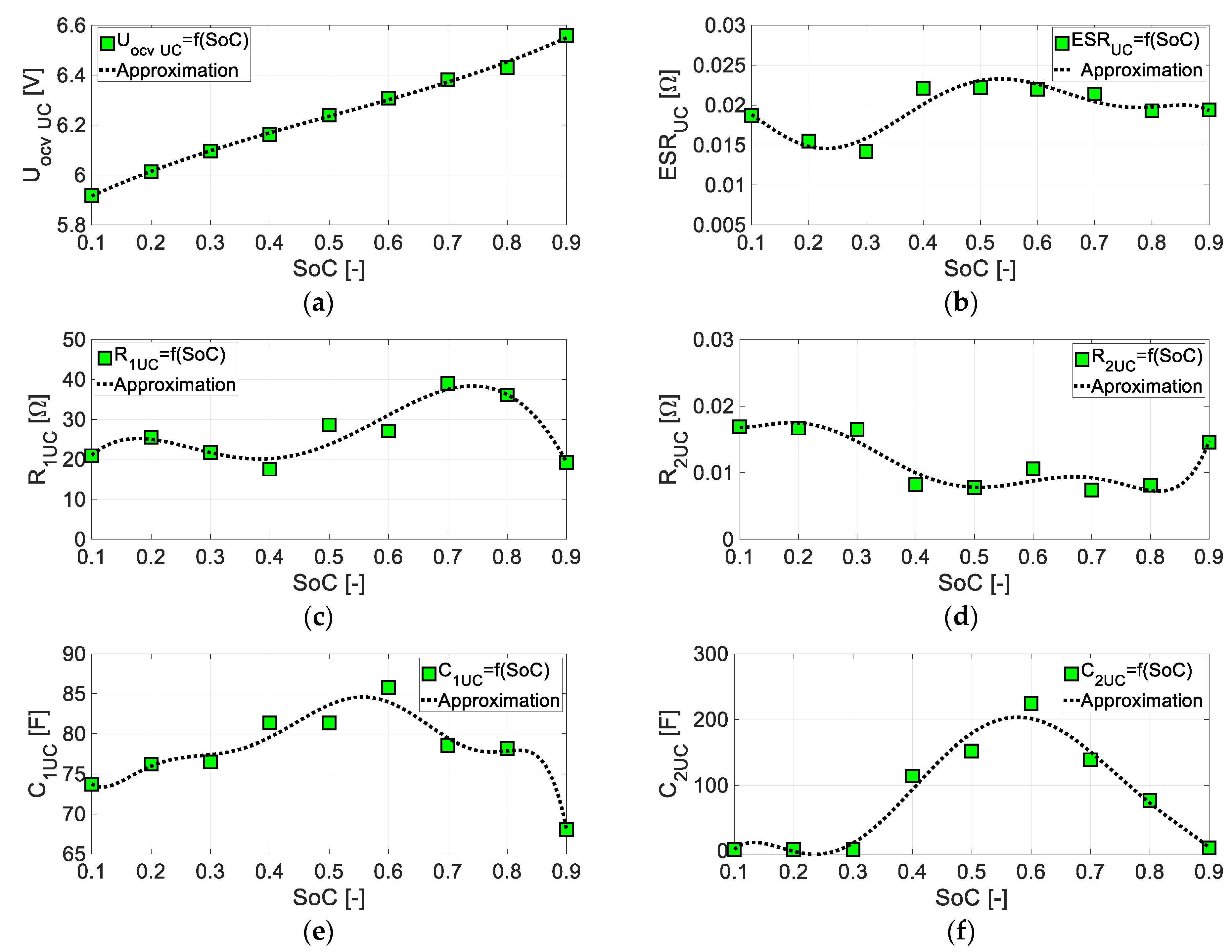
5. The Process of BES-UC Parameter Identification and Error Analysis

5.1. Identification of BES-UC Model Parameters

This subsection outlines the methods for identifying parameters of the components of the parallel-connected battery–ultracapacitor module, an equivalent circuit with two RC loops.
In the system of differential equations that serves as the mathematical model of the hybrid energy storage system (Figure 8) with a parallel connection of a BES and UC, each element consists of two RC loops (2-RC), a series ESR resistor and an electromotive force source. The complete model includes six battery parameters (R1_BES, R2_BES, C1_BES, C2_BES, R0_BES and UOCV_BES) and six ultracapacitor parameters (R1_UC, R2_UC, C1_UC, C2_UC, ESR_UC and EMF_UC). Differential equations describing the system are automatically generated by the MATLAB 2020a SimScape software (a system fragment is shown in Figure 8) but can be provided manually.
The input signal to the loop model is the total current signal obtained from experimental research. This is similar to the method for identifying individual battery and ultracapacitor parameters. Since the battery and the ultracapacitor currents were measured independently during the bench tests, their parameters were identified separately. This approach reduced the number of identified parameters from six to twelve, significantly speeding up the identification process.
By solving the system of differential equations, the voltage waveform across the common terminals of the battery and ultracapacitor (connected in parallel) is estimated as a function of time. The voltage waveform depends on the values assigned to the battery parameters (R1_BES, R2_BES, C1_BES, C2_BES, R0_BES and UOCV_BES) and the ultracapacitor parameters (R1_UC, R2_UC, C1_UC, C2_UC, ESR_UC and EMF_UC). The identification process minimises the difference between the simulated and measured voltage waveform obtained during laboratory tests.
The identification task is to find a set of six battery parameters (R1_BES, R2_BES, C1_BES, C2_BES, R0_BES and UOCV_BES) and six ultracapacitor parameters (R1_UC, R2_UC, C1_UC, C2_UC, ESR_UC and EMF_UC), such that the simulated voltage waveforms and the measured voltage waveforms during testing differ as little as possible. The measure of the identification error is the integral of the squared error e2 = (yEy(Ξ,x,u))2, where y(Ξ,x,u) is the calculated function and yE is the measured value from the tests. The identification process was performed using a “nonlinear data-fitting” procedure that minimised the value of the integral J of the squared error e2 by iteratively modifying the values of the parameter vector Ξ = [R1, R2, C1, C2, ESR/R0, EMF/UOCV]. This was achieved by applying increments ΔΞ = [ΔR1, ΔR2, ΔC1, ΔC2, ΔESR/ΔR0, ΔEMF/ΔUOCV] (for the battery and ultracapacitor, respectively) using the values of the gradient (∇J) and Hessian (H) values, as described by Equations (15)–(17).
J = t 0 t e n d e 2 d t = t 0 t e n d y E y ( Ξ , x , u ) 2 d t
Knowing that
J Ξ = t 0 t e n d 2 e y ( Ξ , x , u ) Ξ d t = t 0 t e n d y E y ( Ξ , x , u ) 2 d t
The Jacobian function J reaches a minimum under the following condition:
J = min J ( Ξ + Δ Ξ ) J ( Ξ ) Δ Ξ = J Ξ Δ Ξ + 1 2 2 J Ξ 2 Δ Ξ 2 = 0 Δ Ξ = 2 J Ξ 2 J Ξ 2 = 2 J H
To modify the parameter values Ξ = [R1, R2, C1, C2, ESR/R0, EMF/UOCV] (for the battery and ultracapacitor, respectively), the Levenberg–Marquardt error backpropagation method was used. This method uses appropriately weighted gradient approximations of the minimised function (∇J) and its Hessian (H), with the Jacobian being recalculated at the end of each iteration. The Jacobian was determined based on the obtained error change Δe, related to the parameter vector change ΔΞ.
The adaptation of parameter vector values Ξ = [R1, R2, C1, C2, ESR/R0, EMF/UOCV], through successive increments ΔΞ = [ΔR1, ΔR2, ΔC1, ΔC2, ΔESR/ΔR0, ΔEMF/ΔUOCV], was carried out iteratively until the stationary value of the integral J of the square error e2 was achieved. This indicated that a local minimum had been reached. Stationarity was defined as changes in the relative value |ΔJ/J| < εps, where εps = 1 × 10⁻¹⁰ was assumed in the performed tests.
The correct assumption of the initial values for the parameters Ξ0 = [R10, R20, C10, C20, ESR0/R0, EMF0/UOCV0] was crucial. Converging to a sub-optimal local solution in gradient-based methods is risky rather than using the global optimum. Therefore, the initial parameter values were set to typical orders of magnitude for the tested battery and ultracapacitor. The following initial conditions were adopted:
  • Battery: Ξ0_BES = [R10_BES = 1.0 × 10, R20_BES = 1.0 × 10⁻², C10_BES = 1.0 × 10, C20_BES = 1.0, R0_BES = 1.0 × 10⁻², UOCV0_BES = 6.0];
  • Ultracapacitor: Ξ0_UC = [R10_UC = 1.0, R20_UC = 1.0 × 10⁻³, C10_UC = 1.0 × 10⁻³, C20_UC = 1.0 × 10, ESR0_UC = 1.0 × 10⁻³, EMF0_UC/UOCV0_UC = 6.0].
Additionally, all parameter values were constrained to be positive during the identification process.
The identified parameters of the 2RC/DP model of the VRLA battery operating in a hybrid module with an ultracapacitor were expressed as polynomial functions of the SoC (0.1 ≤ SoC ≤ 0.9). The general forms are as follows:
R i n t B E S S o C = A R i n t B E S S o C 6 + B R i n t B E S S o C 5 + C R i n t B E S S o C 4 + D R i n t B E S S o C 3 + E R i n t B E S S o C 2 + F R i n t B E S S o C + G R i n t B E S R 1 B E S S o C = A R 1 B E S S o C 6 + B R 1 B E S S o C 5 + C R 1 B E S S o C 4 + D R 1 B E S S o C 3 + E R 1 B E S S o C 2 + F R 1 B E S S o C + G R 1 B E S R 2 B E S S o C = A R 2 B E S S o C 7 + B R 2 B E S S o C 6 + C R 2 B E S S o C 5 + D R 2 B E S S o C 4 + E R 2 B E S S o C 3 + F R 2 B E S S o C 2 + G R 2 B E S S o C + H R 2 B E S C 1 B E S S o C = A C 1 B E S S o C 5 + B C 1 B E S S o C 4 + D C 1 B E S S o C 3 + E C 1 B E S S o C 2 + F C 1 B E S S o C + G C 1 B E S C 2 B E S S o C = A C 2 B E S S o C 5 + B C 2 B E S S o C 4 + D C 2 B E S S o C 3 + E C 2 B E S S o C 2 + F C 2 B E S S o C + G C 2 B E S U O C V B E S ( S o C ) = A U O C V B E S S o C 2 + B U O C V B E S S o C + D U O C V B E S
Table 2 presents the values of the polynomial coefficients for the identified parameters, R1BES(SoC), R2BES(SoC), C1BES(SoC), C2BES(SoC), ESRBES(SoC) and UOCVBES(SoC), as shown in Equation (18).
Figure 9 shows graphs of the identified parameters of the battery: (a) UOCV BES = f(SoC), (b) Rint BES = f(SoC), (c) R1 BES = f(SoC), (d) R2 BES = f(SoC), (e) C1 BES = f(SoC) and (f) C2 BES = f(SoC).
The identified parameters of the 2RC/DP model of the ultracapacitor in a hybrid module with a battery over the SoC range from 0.1 to 0.9 are described by polynomial functions in the following form:
E S R U C ( S o C ) = A E S R U C S o C 6 + B E S R U C S o C 5 + C E S R U C S o C 4 + D E S R U C S o C 3 + E E S R U C S o C 2 + F E S R U C S o C + G E S R U C R 1 UC S o C = A 1 UC S o C 5 + B 1 UC S o C 4 + C 1 UC S o C 3 + D 1 UC S o C 2 + E 1 UC S o C + F 1 UC R 2 UC S o C = A R 2 UC S o C 5 + B R 2 UC S o C 4 + D R 2 UC S o C 3 + E R 2 UC S o C 2 + F R 2 UC S o C + G R 2 UC C 1 UC S o C = A C 1 UC S o C 6 + B C 1 UC S o C 5 + D C 1 UC S o C 4 + E C 1 UC S o C 3 + F C 1 UC S o C 2 + G C 1 UC S o C + H C 1 UC C 2 UC S o C = A C 2 UC S o C 5 + B C 2 UC S o C 4 + D C 2 UC S o C 3 + E C 2 UC S o C 2 + F C 2 UC S o C + G C 2 UC U O C V UC S o C = A U O C V UC S o C 2 + B U O C V UC S o C + D U O C V U C
Table 3 presents the values of the polynomial coefficients of the identified parameters, R1 UC(SoC), R2 UC(SoC), C1 UC(SoC), C2 UC(SoC), ESRUC(SoC) and UOCV UC(SoC), as shown in Equation (19).
Figure 10 shows graphs of the identified parameters of the ultracapacitor: (a) UOCV UC = f(SoC), (b) ESRUC = f(SoC), (c) R1 UC = f(SoC), (d) R2 UC = f(SoC), (e) C1 UC = f(SoC) and (f) C2 UC = f(SoC).

5.2. Error Analysis

This section describes the indicators used to assess the identification accuracy of parameter identification. The BES voltage estimation error is defined as follows:
e r r ( k ) = y D P ( j ) y ( j )
where y(j) = Uz experiment(j) is the experimental voltage, yDP(j) = Uz model DP(j) is the model voltage and j is the number of samples.
The Mean Square Error (MSE) is calculated as follows:
M S E = 1 N k = 1 N [ e r r ( j ) ] 2
The quality of a single resistive–capacitive model (DP) with two RC loops for the battery and the ultracapacitor was evaluated using the MSE, while the goodness of fit between the model-estimated data from the model and the experimental data were evaluated using the Normalised Root Mean Square Error (NRMSE) against 1 [77]:
N R M S E ( j ) = 1 e r r ( j ) y ( j ) y ¯
where y ¯ is the average value of the modelled signal. The NRSME value ranges from –∞ to 1, where a value close to 1 indicates a good fit.
The summary tables in Section 6 present the MSE and NRMSE values for the considered SoC values during pseudo-random cycles for the hybrid BES-UC systems.

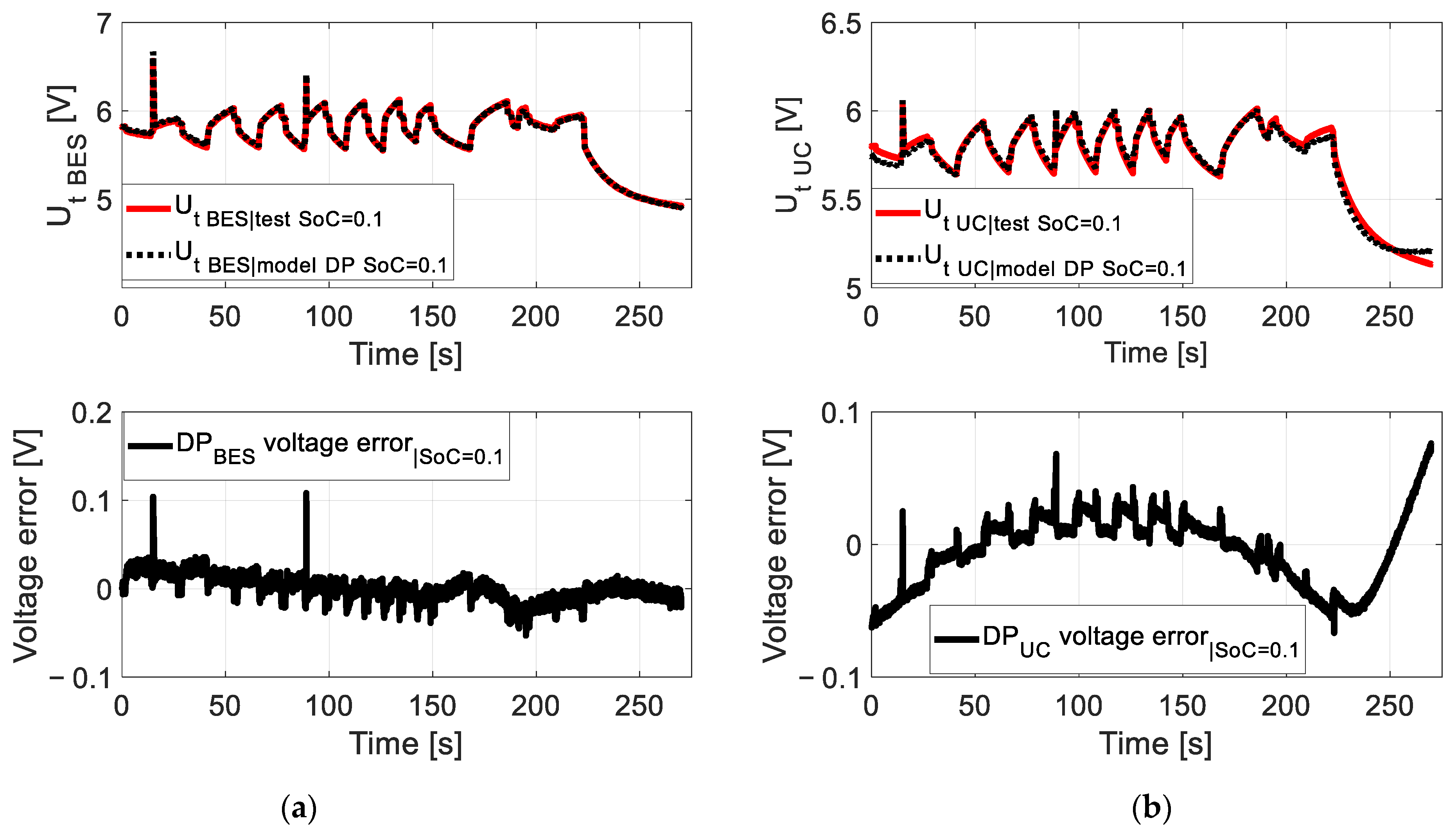
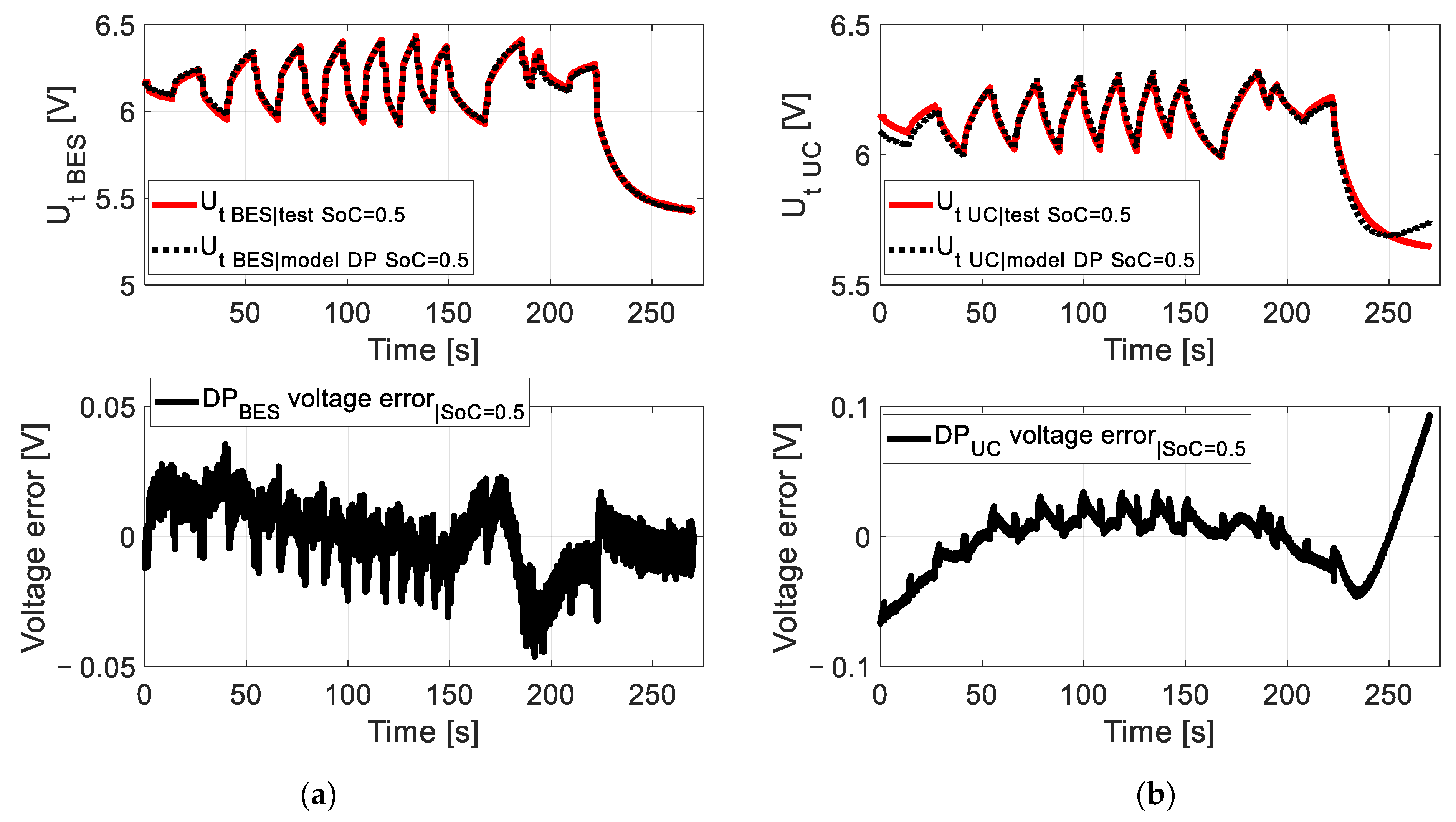
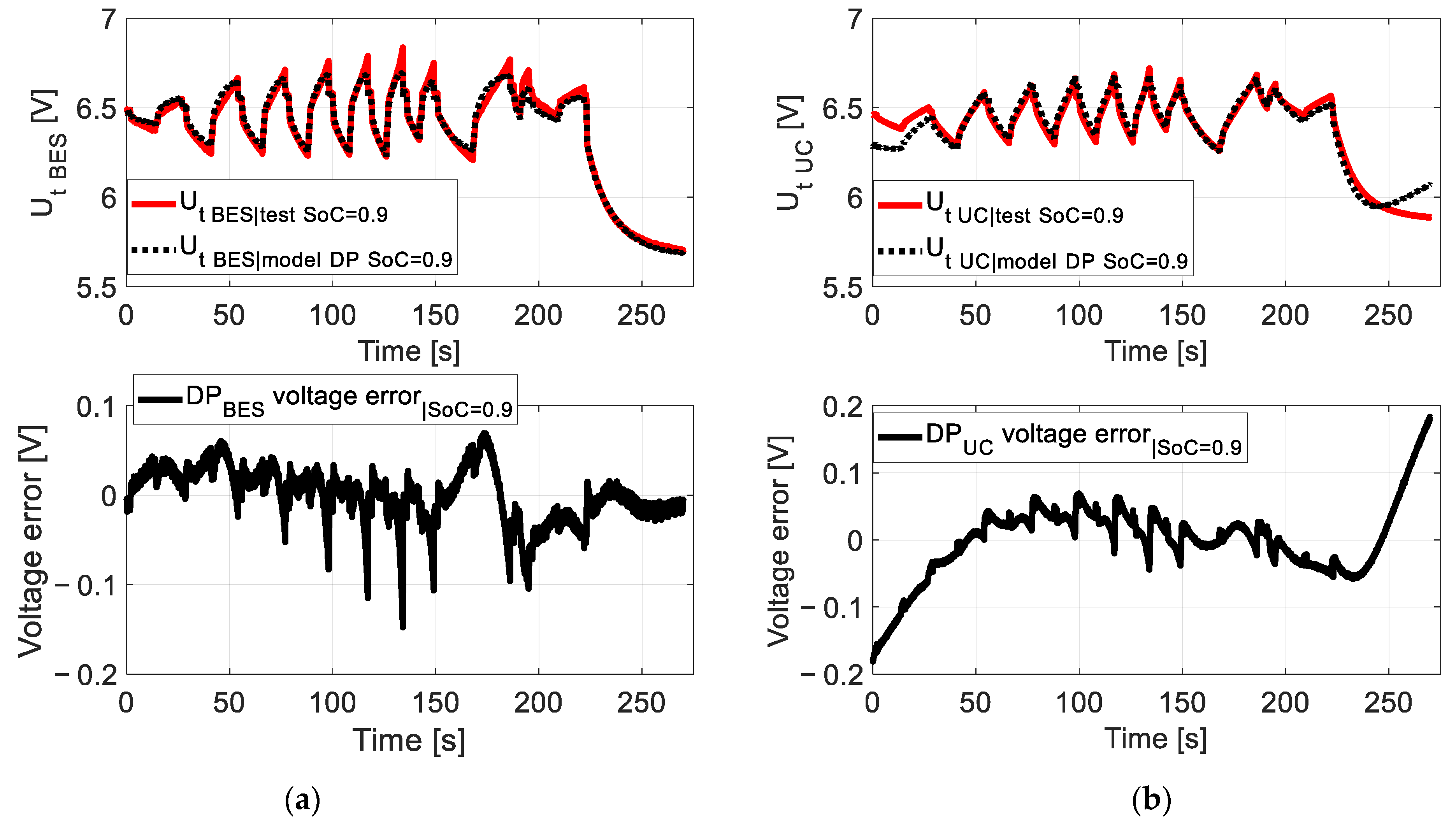
6. Comparison of Results Obtained from the Experiment and the Model for the HESS

This section presents validation results of voltage waveforms in the hybrid system, incorporating the battery (BES) and an ultracapacitor (UC) using the 2-RC model. The results cover SoC values from 0.1 to 0.9. Selected results for SoC = 0.1, 0.5 and 0.9 are shown in the following figures:
SoC = 0.1: Figure 11a (BES) and Figure 11b (UC);
SoC = 0.5: Figure 12a (BES) and Figure 12b (UC);
SoC = 0.9: Figure 13a (BES) and Figure 13b (UC).
All of the examples are shown for a pseudo-random pulse loading cycle.
The maximum voltage error for the battery and ultracapacitor occurred at SoC = 0.9:
For the battery, the maximum error was 0.15 V (Figure 13a);
For the ultracapacitor, the maximum voltage error was 0.19 V (Figure 13b).
In other cases, for both the battery and the ultracapacitor, within the SoC range from 0.1 to 0.8, the voltage error did not exceed 0.12 V. The results obtained are considered satisfactory.
Table 4 includes a comparison of the results obtained from the experiment and the model presented in papers [47,54,55,57,78] and the HESS presented in this paper.
Table 5 summarises the MSE and NRMSE values for SoC values ranging from 0.1 to 0.9. The MSE values are low:
-
For the battery, they do not exceed 1.1 × 10⁻³ (at SoC = 0.9).
-
For the ultracapacitor, they do not exceed 2.4 × 10⁻³ (at SoC = 0.9).
The lowest NRMSE value for the battery is 0.7597 at SoC = 0.9, while for the ultracapacitor, it is 0.4468 at SoC = 0.4. Adding more RC loops could increase the model’s accuracy, as shown in [47,48,49,50,51,52,53,54,55,79] and in Table 4. However, this comes at the cost of significantly longer parameter identification times. The approach presented in this paper represents a compromise between achieving high accuracy in estimating unmeasurable parameters, minimising parameter identification time and maintaining the accuracy of the identified parameters.
For a 1-RC loop, it is necessary to identify four parameters for the battery (R1_BES, C1_BES, R0_BES and UOCV_BES) and four for the ultracapacitor (R1 UC, C1 UC, ESRUC and UOCV UC), for a total of eight parameters. For a 2-RC loop (as used in this work), twelve parameters need to be identified for both components. For a 3-RC loop, the number increases to sixteen parameters, while for a 4-RC loop, it increases to twenty parameters.
As shown in [79], using more than two 2-RC loops does not significantly improve the accuracy of voltage estimation. However, it significantly increases the time required to identify the model parameters, even by a factor of several times.

7. Conclusions and Recommendations

This study presents experimental and modelling research on energy storage using a battery–ultracapacitor module in a passive parallel connection. These energy storage systems have potential applications in various transport and infrastructure segments, including electric vehicles, plug-in hybrid vehicles, machines, wheelchairs and mobile robots, considering scalability. Table 6 summarises the potential applications of BES, UC and HESS energy storage technologies and recommendations for their use in the transportation and infrastructure sectors.
The main advantages, disadvantages and limitations of the HESS study based on the 2-RC model are presented in Table 7. The HESS module has several advantages in mobile applications, including limiting currents, smoothing voltage variations in the system, and achieving high energy density (battery effect) and high power density (ultracapacitor effect), which are included in Table 7. However, the main disadvantages of such a module in mobile applications are higher cost, increased system mass and the need to monitor the voltage of each component in the system through the BMS.
Another significant advantage of hybrid energy storage in stationary applications is its potential for the start-up of massive gas engine-powered systems, particularly those transported by gas engine systems used at temporary events such as concerts. These stores can also be used with wind turbines and other renewable energy sources to increase flexibility. Their use in zero-emission buildings and off-grid installations is recommended, considering households’ and prosumer farms’ daily energy demand cycles equipped with micro-renewable energy systems. Hybrid energy storage can contribute to developing sustainable infrastructure for electric vehicles using only renewable energy. This could accelerate their development, particularly on intercity routes and in low-density areas.
This work highlights the usefulness of a novel analysis method using models based on replacement diagrams with a 2-RC loop for modelling HESSs in the form of a battery and an ultracapacitor connected in a passive parallel topology. The MSE values for the battery and the ultracapacitor did not exceed 0.0024, while the NRMSE values were not lower than 0.7597 for the battery and 0.4468 for the ultracapacitor, respectively, at SoC = 0.9. These results confirm that the developed simulation models based on equivalent schemes provide highly accurate results and can be used for model-based estimation of non-measurable parameters for the battery–ultracapacitor module. The obtained results can assist in the component selection process for HESSs in EV propulsion systems and distributed generation devices.
To foster future perspectives and the study’s limitations, we suggest the following:
-
The exploration of advanced battery management systems (BMSs) for real-time monitoring and balancing is recommended.
-
Integrating hybrid energy storage with smart grids is recommended to optimise energy flow and improve grid stability.
-
Exploration of the 2-RC loop modelling process is recommended to ensure the maintenance of accuracy whilst reducing computational intensity for real-time applications.
-
The research should be extended beyond VRLA-AGM batteries and Maxwell ultracapacitors to enhance the generalisability of findings to other energy storage technologies.

Author Contributions

Conceptualization: A.C.; Data curation: A.C. and K.B.; Formal analysis: A.C.; Investigation: A.C. and K.B.; Methodology: A.C. and P.P.; Software: A.C. and K.B.; Supervision: A.C. and P.P.; Visualisation: A.C. and P.P.; Writing—original draft: A.C. and K.B.; Writing—review and editing: A.C., P.P., K.B., J.M., A.K., P.K., J.L., S.O. and R.C.-C. All authors have read and agreed to the published version of the manuscript.

Funding

Studies were funded by the ENERGYTECHDEMO project grant by Warsaw University of Technology under the programme Excellence Initiative: Research University (IDUB), No. CPR-IDUB/118/Z01/POB7/2024.

Data Availability Statement

The authors will make the raw data supporting this study’s findings available upon reasonable request.

Conflicts of Interest

The authors declare no conflicts of interest.

Abbreviations

The following abbreviations are used in this manuscript:
Acronyms
AGMAbsorbent Glass Mat
BESBattery Energy Storage
BEV/EVBattery Electric Vehicle/Electric Vehicle
BMSBattery Management System
DP/2RCDual Polarisation/2-Resistive-Capacitance
DSTDynamic Stress Test
EKFExtended Kalman Filter
EUEuropean Union
FCFuel Cell
FTP-75Federal Test Procedure
GHGGreenhouse Gas Emission
HPPCHybrid Pulse Power Characterisation
HESSHybrid Energy Storage System
MAEMean Absolute Error
MSEMean Square Error [–]
n.a.not applicable
NRMSENormalised Root Mean Square Error [–]
OCVOpen-Circuit Voltage [V]
PVPhotovoltaic
RCResistive–Capacitive
RESRenewable Energy Source
RLSRecursive Least Square
RMSERoot Mean Square Error
SoCState of Charge
SoHState of Health
TEN-TTrans-European Transport Network
UCUltracapacitor
UDDSUrban Dynamometer Driving Schedule
UKFUnscented Kalman Filter
VRLAValve-Regulated Lead Acid
Greek symbols/subscripts/superscripts
C,C1,C2,
Cel, Cs2
Capacitances [F]
EBESThe energy stored in the battery [J]
EUC + BESThe energy stored in the HESS based on the battery and ultracapacitor [J]
EUCThe energy stored in the ultracapacitor [J]
errError
EMFElectromotive force [V]
ESREquivalent series resistance [Ω]
HHessian
iTotal pulse current [A]
ibTotal loading current flow battery elements [A]
ib1,ib2Currents flowing through battery elements [A]
iucCurrent flowing through ultracapacitor elements [A]
jSample number [–]
JJacobian
LInductance [H]
NNumber of data samples [–]
UOCV/
OCVBES/
OCVUC
Open-circuit voltage of battery (BES) and ultracapacitor (UC) [V]
R0 (Rint) Ohmic resistance [Ω]
R1Activation polarisation resistance [Ω]
R2Concentration polarisation resistance [Ω]
Rel, Rsel2Resistances [Ω]
QbatEffective capacity [Ah]
QnNominal capacity [Ah]
QmaxMaximum battery capacity [Ah]
QminMinimum battery capacity [Ah]
TambientAmbient temperature [K]
TbodyBody temperature [K]
TtermTemperature at terminals [K]
U1,U2Voltage drops [V]
UchCharging/discharging voltage [V]
UdchDischarging voltage [V]
V2Variance [-]
JGradient
ΞParameter vector [-]
εpsStationarity condition [-]

References

  1. Paris Agreement, United Nations, 2015 (art. 2 par. 1a & art. 4 par. 4). Available online: https://unfccc.int/sites/default/files/resource/parisagreement_publication.pdf (accessed on 20 November 2024).
  2. European Green Deal, Communication from the Commission to the European Parliament, the European Council, the Council, the European Economic and Social Committee and the Committee of the Regions The European Green Deal (COM (2019) 640 Final). Available online: https://eur-lex.europa.eu/resource.html?uri=cellar:b828d165-1c22-11ea-8c1f-01aa75ed71a1.0002.02/DOC_1&format=PDF (accessed on 21 October 2024).
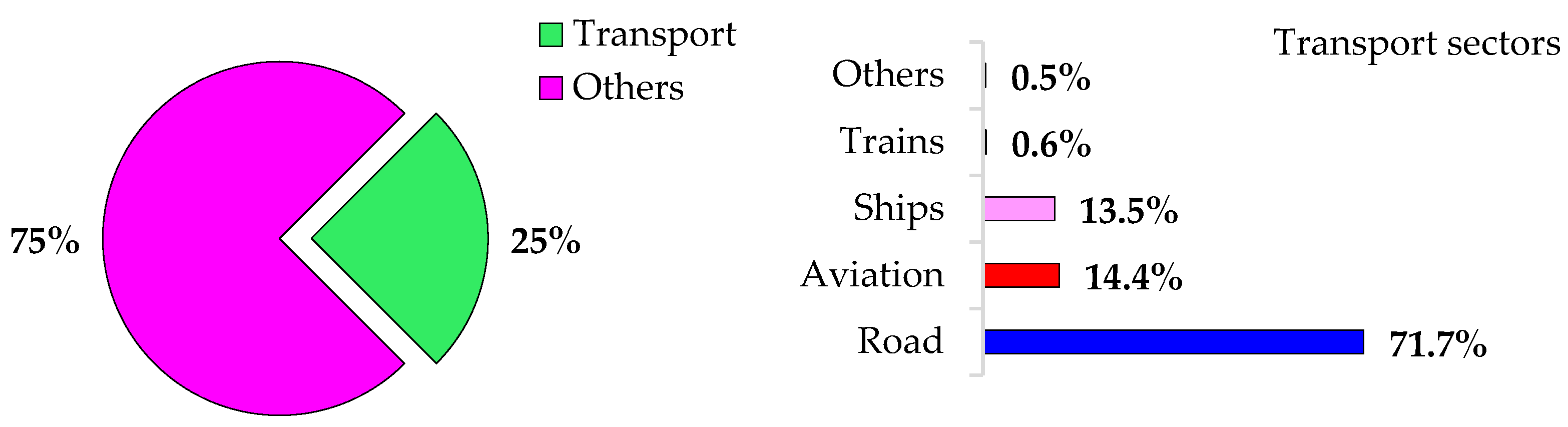
  3. Transport GHG Emission in EU. Available online: https://www.consilium.europa.eu/en/infographics/fit-for-55-afir-alternative-fuels-infrastructure-regulation/ (accessed on 20 November 2024).
  4. ChaoJi 3.0 Standard. Available online: https://www.vector.com/int/en/know-how/protocols/gbt-27930/#c204146 (accessed on 22 November 2024).
  5. White Paper of ChaoJi EV Charging Technology, State Grid Corporation of China Electricity Council Jointly Released June 2020. Available online: https://www.chademo.com/chaoji-gbt-standards-released (accessed on 20 October 2024).
  6. IEC 61851-23:2014; Electric Vehicle Conductive Charging System—Part 23: DC Electric Vehicle Charging Station. IEC: Geneva, Switzerland, 2014. Available online: https://www.iecee.org/certification/iec-standards/iec-61851-232014 (accessed on 22 November 2024).
  7. Regulation of The European Parliament and of the Council on the Deployment of Alternative Fuels Infrastructure, and Repealing Directive 2014/94/EU of the European Parliament and of the Council. Available online: https://eur-lex.europa.eu/resource.html?uri=cellar:dbb134db-e575-11eb-a1a5-01aa75ed71a1.0001.02/DOC_1&format=PDF (accessed on 22 November 2024).
  8. Directives Directive (EU) 2018/2001 of the European Parliament and of the Council of 11 December 2018 on the Promotion of the Use of Energy from Renewable Sources. Available online: https://eur-lex.europa.eu/legal-content/EN/TXT/PDF/?uri=CELEX:32018L2001&from=EN (accessed on 23 November 2024).
  9. Revision of the Renewable Energy Directive: Fit for 55 Package. Available online: https://www.europarl.europa.eu/RegData/etudes/BRIE/2021/698781/EPRS_BRI(2021)698781_EN.pdf (accessed on 22 November 2024).
  10. Chmielewski, A.; Gumiński, R.; Mączak, J.; Radkowski, S.; Szulim, P. Aspects of balanced development of RES and distributed micro-cogeneration use in Poland: Case study of muCHP with Stirling engine. Renew. Sustain. Energy Rev. 2016, 60, 930–952. [Google Scholar] [CrossRef]
  11. Wasim, M.S.; Habib, S.; Amjad, M.; Bhatti, A.R.; Ahmed, E.M.; Qureshi, M.A. Battery-Ultracapacitor Hybrid Energy Storage System to Increase Battery Life Under Pulse Loads. IEEE Access 2022, 10, 62173–62182. [Google Scholar] [CrossRef]
  12. Jankowska, E.; Kopciuch, K.; Błażejczyk, M.; Majchrzycki, W.; Piórkowski, P.; Chmielewski, A.; Bogdziński, K. Hybrid energy storage based on ultracapacitor and lead acid battery: Case study. In Automation 2018: Advances in Intelligent Systems and Computing; Szewczyk, R., Zieliński, C., Kaliczyńska, M., Eds.; Springer: Cham, Switzerland, 2018; Volume 743, pp. 339–349. [Google Scholar]
  13. Piórkowski, P.; Chmielewski, A.; Bogdziński, K.; Możaryn, J.; Mydłowski, T. Research on Ultracapacitors in Hybrid systems: Case Study. Energies 2018, 11, 2551. [Google Scholar] [CrossRef]
  14. Chariot, Electric Buses. Available online: https://chariot-electricbus.com/cmproduct/battery-electric-buses/ (accessed on 22 November 2024).
  15. Chariot, Ultracapacitor e-Bus. Available online: https://chariot-electricbus.com/cmproduct/12m-ultracapacitor-chariot-e-bus/ (accessed on 22 November 2024).
  16. Maxwell. Available online: https://maxwell.com/products/ultracapacitors/ (accessed on 22 November 2024).
  17. Hannan, M.A.; Lipu, M.S.H.; Hussain, A.; Mohamed, A. A review of lithium–ion battery state of charge estimation and management system in electric vehicle applications: Challenges and recommendations. Renew. Sustain. Energy Rev. 2017, 78, 834–854. [Google Scholar] [CrossRef]
  18. Chmielewski, A.; Szulim, P.; Gregorczyk, M.; Gumiński, R.; Mydłowski, T.; Mączak, J. Model of an electric vehicle powered by a PV cell—A case study. In Proceedings of the 2017 22nd International Conference on Methods and Models in Automation and Robotics (MMAR), Miedzyzdroje, Poland, 28–31 August 2017; pp. 1009–1014. [Google Scholar]
  19. Naresh, P.; Sai Vinay Kishore, N.; Seshadri Sravan Kumar, V. A new configuration for enhanced integration of a battery–ultracapacitor system. Renew. Energy 2024, 229, 120708. [Google Scholar]
  20. Chien–Hsing, L.; Shih–Hsien, H. Prediction of Equivalent–Circuit Parameters for Double–Layer Capacitors Module. IEEE Trans. Energy Convers. 2013, 28, 913–920. [Google Scholar]
  21. Kopczyński, A.; Piórkowski, P.; Roszczyk, P. Parameters selection of extended-range electric vehicle powered from supercapacitor pack based on laboratory and simulation tests. IOP Conf. Ser. Mater. Sci. Eng. 2016, 421, 022016. [Google Scholar]
  22. Esfandyaria, A.; Nortona, B.; Conlona, M.; McCormack, S.J. Performance of a campus photovoltaic electric vehicle charging station in a temperate climate. Sol. Energy 2019, 177, 762–771. [Google Scholar] [CrossRef]
  23. Akar, F.; Tavlasoglu, Y.; Vural, B. An Energy Management Strategy for a Concept Battery/Ultracapacitor Electric Vehicle with Improved Battery Life. IEEE Trans. Transp. Electrif. 2017, 3, 191–200. [Google Scholar] [CrossRef]
  24. Demircalı, A.; Sergeant, P.; Koroglu, S.; Kesler, S.; Oztürk, E.; Tumbek, M. Influence of the temperature on energy management in battery–ultracapacitor electric vehicles. J. Clean. Prod. 2018, 176, 716–725. [Google Scholar] [CrossRef]
  25. Hung, N.B.; Jaewon, S.; Lim, O. A study of the effects of input parameters on the dynamics and required power of an electric bicycle. Appl. Energy 2017, 204, 1347–1362. [Google Scholar] [CrossRef]
  26. Jia–Sheng, H.; Fei, L.; Chong, Z.; Chang–Yi, C.; Sin–Li, C.; Tsai–Jiun, R.; Chunting, C.M. Hybrid Energy Storage System of an Electric Scooter Based on Wireless Power Transfer. IEEE Trans. Ind. Inform. 2018, 14, 4169–4178. [Google Scholar]
  27. Hsu, Y.C.; Kao, S.C.; Ho, C.Y.; Jhou, P.H.; Lu, M.Z.; Liaw, C.M. On an Electric Scooter With G2V/V2H/V2G and Energy Harvesting Functions. IEEE Trans. Power Electron. 2018, 33, 6910–6925. [Google Scholar] [CrossRef]
  28. Chmielewski, A.; Piórkowski, P.; Bogdzinski, K.; Szulim, P.; Guminski, R. Test bench and model research of hybrid energy storage. J. Power Technol. 2017, 97, 406–415. [Google Scholar]
  29. Chmielewski, A.; Bogdziński, K.; Gumiński, R.; Szulim, P.; Piórkowski, P.; Możaryn, J.; Mączak, J. Operational research of VRLA battery. In Automation 2018: Advances in Intelligent Systems and Computing; Szewczyk, R., Zieliński, C., Kaliczyńska, M., Eds.; Springer: Cham, Switzerland, 2018; Volume 743, pp. 783–791. [Google Scholar]
  30. Czerwiński, A. Akumulatory, Baterie, Ogniwa; Wyd. WKŁ: Sulejówek, Poland, 2012. [Google Scholar]
  31. Kollmeyer, P.K.; Jahns, T.M. Aging and performance comparison of absorbed glass matte, enhanced flooded, PbC, NiZn, and LiFePO4 12V start stop vehicle batteries. J. Power Sources 2019, 441, 227139. [Google Scholar] [CrossRef]
  32. Park, J.; Appiah, W.A.; Byun, S.; Jin, D.; Ryou, M.-H.; Lee, Y.M. Semi-empirical long-term cycle life model coupled with an electrolyte depletion function for large-format graphite/LiFePO4 lithium-ion batteries. J. Power Sources 2017, 365, 257–265. [Google Scholar] [CrossRef]
  33. Sarasketa-Zabala, E.; Gandiaga, I.; Martinez-Laserna, E.; Rodriguez-Martinez, L.M.; Villarreal, I. Cycle ageing analysis of a LiFePO4/graphite cell with dynamic model validations: Towards realistic lifetime predictions. J. Power Sources 2015, 275, 573–587. [Google Scholar] [CrossRef]
  34. Wang, J.; Liu, P.; Hicks-Garner, J.; Sherman, E.; Soukiazian, S.; Verbrugge, M.; Tataria, H.; Musser, J.; Finamore, P. Cycle-life model for graphite-LiFePO4 cells. J. Power Sources 2011, 196, 3942–3948. [Google Scholar] [CrossRef]
  35. Liang, J.; Gan, Y.; Yao, M.; Li, Y. Numerical analysis of capacity fading for a LiFePO4 battery under different current rates and ambient temperatures. Int. J. Heat Mass Transf. 2021, 165, 120615. [Google Scholar] [CrossRef]
  36. Li, J.; Adewuyi, K.; Lotfi, N.; Landers, R.; Park, J. A single particle model with chemical/mechanical degradation physics for lithium ion battery State of Health (SOH) estimation. Appl. Energy 2018, 212, 1178–1190. [Google Scholar] [CrossRef]
  37. Xiong, R.; Li, L.; Tian, J. Towards a smarter battery management system: A critical review on battery state of health monitoring methods. J. Power Sources 2018, 405, 18–29. [Google Scholar] [CrossRef]
  38. Tian, J.; Xiong, R.; Shen, W.; Lu, J.; Sun, F. Flexible battery state of health and state of charge estimation using partial charging data and deep learning. Energy Storage Mater. 2022, 51, 372–381. [Google Scholar] [CrossRef]
  39. Lu, J.; Xiong, R.; Tian, J.; Wang, C.; Hsu, C.W.; Tsou, N.T.; Sun, F.; Li, J. Battery degradation prediction against uncertain future conditions with recurrent neural network enabled deep learning. Energy Storage Mater. 2022, 50, 139–151. [Google Scholar] [CrossRef]
  40. Tian, J.; Xiong, R.; Lu, J.; Chen, C.; Shen, W. Battery state-of-charge estimation amid dynamic usage with physics-informed deep learning. Energy Storage Mater. 2022, 50, 718–729. [Google Scholar] [CrossRef]
  41. Tian, J.; Xiong, R.; Shen, W. State-of-Health Estimation Based on Differential Temperature for Lithium Ion Batteries. IEEE Trans. Power Electron. 2020, 35, 10363–10373. [Google Scholar] [CrossRef]
  42. Yang, R.; Xiong, R.; Ma, S.; Lin, X. Characterization of external short circuit faults in electric vehicle Li-ion battery packs and prediction using artificial neural networks. Appl. Energy 2020, 260, 114253. [Google Scholar] [CrossRef]
  43. Wu, S.; Xiong, R.; Li, H.; Nian, V.; Ma, S. The state of the art on preheating lithium-ion batteries in cold weather. J. Energy Storage 2020, 27, 101059. [Google Scholar] [CrossRef]
  44. Chen, C.; Xiong, R.; Yang, R.; Shen, W.; Sun, F. State-of-charge estimation of lithium-ion battery using an improved neural network model and extended Kalman filter. J. Clean. Prod. 2019, 234, 1153–1164. [Google Scholar] [CrossRef]
  45. Hossain Lipu, M.S.; Hannan, M.A.; Hussain, A.; Hoque, M.M.; Ker, P.J.; Saad, M.H.M.; Ayob, A. A review of state of health and remaining useful life estimation methods for lithium–ion battery in electric vehicles: Challenges and recommendations. J. Clean. Prod. 2018, 205, 115–133. [Google Scholar] [CrossRef]
  46. Linxiao, G.; Denecke, M.E.; Foley, S.B.; Dong, H.; Qi, Z.; Koenig, G.M., Jr. Electrochemical characterization of lithium cobalt oxide within aqueous flow suspensions as an indicator of rate capability in lithiumion battery electrodes. Electrochim. Acta 2018, 281, 822–830. [Google Scholar]
  47. He, H.; Xiong, R.; Fan, J. Evaluation of Lithium–Ion Battery Equivalent Circuit Models for State of Charge Estimation by an Experimental Approach. Energies 2011, 4, 582–598. [Google Scholar] [CrossRef]
  48. Yao, L.W.; Aziz, J.A.; Ramli, N. Detail analysis of RC parallel network–based model for high capacity lithium ferro phosphates battery. In Proceedings of the 6th IET International Conference on Power Electronics, Machines and Drives (PEMD 2012), Bristol, UK, 27–29 March 2012; pp. 1–6. [Google Scholar]
  49. Li, S.; Cheng, X. A comparative study on RC models of lithium–ion battery. In Proceedings of the 2014 IEEE Conference and Expo Transportation Electrification Asia–Pacific (ITEC Asia–Pacific), Beijing, China, 31 August–3 September 2014; pp. 1–4. [Google Scholar]
  50. Piao, C.; Yang, X. An improved model based on artificial neural networks and Thevenin model for nickel metal hydride power battery. In Proceedings of the International Conference on Optics, Photonics and Energy Engineering (OPEE), Wuhan, China, 10–11 May 2010; pp. 115–118. [Google Scholar]
  51. Putra, W.S.; Dewangga, B.R.; Cahyadi, A.; Wahyunggoro, O. Current Estimation Using Thevenin Battery Model. In Proceedings of the Joint International Conference on Electric Vehicular Technology and Industrial, Mechanical, Electrical and Chemical Engineering (ICEVT & IMECE), Surakarta, Indonesia, 4–5 November 2015; pp. 5–9. [Google Scholar]
  52. Gao, W.; Jiang, M. Research on PNGV Model Parameter Identification of LiFePO4 Li–ion Battery Based on FMRLS. In Proceedings of the 6th IEEE Conference on Industrial Electronics and Applications, Beijing, China, 21–23 June 2011; pp. 2294–2297. [Google Scholar]
  53. Han, Y.; Wang, X. WPT Charging System for Lithium Battery Based on PNGV Model. In Proceedings of the IEEE Transportation Electrification Conference and Expo, Asia–Pacific (ITEC Asia–Pacific), Harbin, China, 7–10 August 2017; pp. 1–5. [Google Scholar]
  54. Liu, X.; Li, W.; Zhou, A. PNGV Equivalent Circuit Model and SOC Estimation Algorithm for Lithium Battery Pack Adopted in AGV Vehicle. IEEE Access 2018, 6, 23639–23647. [Google Scholar] [CrossRef]
  55. Bottinger, M.; Paulitschke, M.; Bocklisch, T. Systematic Experimental Pulse Test Investigation for Parameter Identification of an Equivalent Circuit Based Lithium–Ion Battery Model. Energy Procedia 2017, 135, 337–346. [Google Scholar] [CrossRef]
  56. Cheng, P.; Zhou, Y.; Song, Z.; Ou, Y. Modeling and SOC Estimation of LiFePO4 Battery. In Proceedings of the IEEE International Conference on Robotics and Biomimetics, Qingdao, China, 3–7 December 2016; pp. 2140–2144. [Google Scholar]
  57. Sepasi, S.; Ghorbani, R.; Liaw, B.Y. Inline State of Health Estimation of Lithium–Ion Batteries Using State of Charge Calculation. J. Power Sources 2015, 299, 246–254. [Google Scholar] [CrossRef]
  58. Zhang, C.; Allafi, W.; Dinh, Q.; Ascencio, P.; Marco, J. Online Estimation of Battery Equivalent Circuit Model Parameters and State of Charge Using Decoupled Least Squares Technique. Energy 2018, 142, 678–688. [Google Scholar] [CrossRef]
  59. Ke, M.Y.; Chiu, Y.H.; Wu, C.Y. Battery Modelling and SOC Estimation of a LiFePO4 Battery. In Proceedings of the 2016 International Symposium on Computer, Consumer and Control, Xi’an, China, 4–6 July 2016; pp. 208–211. [Google Scholar]
  60. Pattipati, B.; Balasingam, B.; Avvari, G.V.; Pattipati, K.R.; Bar–Shalom, Y. Open circuit voltage characterization of lithium–ion batteries. J. Power Sources 2014, 269, 317–333. [Google Scholar] [CrossRef]
  61. Dusonchet, L.; Favuzza, S.; Massaro, F.; Telaretti, E.; Zizzo, G. Technological and legislative status point of stationary energy storages in the EU. Renew. Sustain. Energy Rev. 2019, 101, 158–167. [Google Scholar] [CrossRef]
  62. Xiong, R.; Chen, H.; Wang, C.; Sun, F. Towards a smarter hybrid energy storage system based on battery and ultracapacitor—A critical review on topology and energy management. J. Clean. Prod. 2018, 202, 1228–1240. [Google Scholar] [CrossRef]
  63. Eddahech, A.; Briat, O.; Bertrand, N.; Delétage, J.Y.; Vinassa, J.M. Behavior and State–of–Health Monitoring of Li–ion Batteries Using Impedance Spectroscopy and Recurrent Neural Networks. Int. J. Electr. Power Energy Syst. 2012, 42, 487–494. [Google Scholar] [CrossRef]
  64. Lai, Y.; Du, S.; Ai, L.; Cheng, L.Y.; Ji, M. Insight Into Heat Generation Of Lithium–Ion Batteries Based On The Electrochemical–Thermal Model At High Discharge Rates. Int. J. Hydrogen Energy 2015, 40, 13039–13049. [Google Scholar] [CrossRef]
  65. Li, J.; Cheng, Y.; Jia, M.; Tang, Y.; Lin, Y.; Zhian, Z.; Liu, Y. An Electrochemical– Thermal Model Based on Dynamic Responses for Lithium Iron Phosphate Battery. J. Power Sources 2014, 255, 130–143. [Google Scholar] [CrossRef]
  66. Saito, Y.; Shikano, M.; Kobayashi, H. Heat Generation Behavior During Charging and Discharging of Lithium– Ion Batteries After Long– Time Storage. J. Power Sources 2013, 244, 294–299. [Google Scholar] [CrossRef]
  67. Buller, S.; Karden, E.; Kok, D.; De Doncker, W.R. Modeling the dynamic behavior of supercapacitors using impedance spectroscopy. IEEE Trans. Ind. Appl. 2002, 38, 1622–1626. [Google Scholar] [CrossRef]
  68. Ramadan, H.S.; Becherif, M.; Claude, F. Extended kalman filter for accurate state of charge estimation of lithium-based batteries: A comparative analysis. Int. J. Hydrogen Energy 2017, 42, 29033–29046. [Google Scholar] [CrossRef]
  69. Mohamed, A.H.; Schwarz, K.P. Adaptive Kalman Filtering for INS/GPS. J. Geod. 1999, 73, 193–203. [Google Scholar] [CrossRef]
  70. He, H.; Xiong, R.; Zhang, X.; Sun, F.; Fan, J.X. State-of-Charge Estimation of the Lithium-Ion, Battery Using an Adaptive Extended Kalman Filter Based on an Improved Thevenin Model. IEEE Trans. Veh. Technol. 2011, 60, 1461–1469. [Google Scholar]
  71. Chia, Y.Y.; Lee, L.H.; Shafiabady, N. A load predictive energy management system for supercapacitor –battery hybrid energy storage system in solar application using the Support Vector Machine. Appl. Energy 2015, 137, 588–602. [Google Scholar] [CrossRef]
  72. Hredzak, B.; Agelidis, V.G.; Demetriades, G. Application of explicit model predictive control to a hybrid battery ultracapacitor power source. J. Power Sources 2015, 277, 84–94. [Google Scholar] [CrossRef]
  73. Gu, R.; Malysz, P.; Emadi, A. A Novel Battery/Ultracapacitor Hybrid Energy Storage System Analysis based on Physics-Based Lithium-Ion Battery Modeling. In Proceedings of the 2015 IEEE Transportation Electrification Conference and Expo (ITEC), Dearborn, MI, USA, 14–17 June 2015. [Google Scholar]
  74. Rafik, F.; Gualous, H.; Gallay, R.; Crausaz, A.; Berthon, A. Frequency, thermal and voltage supercapacitor characterization and modeling. J. Power Sources 2007, 165, 928–934. [Google Scholar] [CrossRef]
  75. Kalogirou, S.A.; Mellit, A. Artificial intelligence techniques for photovoltaic applications: A review. Prog. Energy Combust. Sci. 2008, 34, 574–632. [Google Scholar]
  76. Szumanowski, A.; Piórkowski, P.; Chang, Y. Batteries and Ultracapacitors Set in Hybrid Propulsion System. In Proceedings of the 2007 International Conference on Power Engineering, Energy and Electrical Drives, Setubal, Portugal, 12–14 April 2007; pp. 122–127. [Google Scholar]
  77. Hyndman, R.J.; Koehler, A.B. Another Look at Measures of Forecast Accuracy. Int. J. Forecast. 2006, 22, 679–688. [Google Scholar] [CrossRef]
  78. Wang, Y.; Liu, C.; Pan, R.; Chen, Z. Modeling and state-of-charge prediction of lithium-ion battery and ultracapacitor hybrids with a co-estimator. Energy 2017, 121, 739–750. [Google Scholar] [CrossRef]
  79. Jackey, R.; Saginaw, M.; Sanghvi, P.; Gazzarri, J.; Huria, T.; Ceraolo, M. Battery Model Parameter Estimation Using a Layered Technique: An Example Using a Lithium Iron Phosphate Cell; SAE Technical Paper 2013 01–1547; Detroit: Michigan, MI, USA, 2013; pp. 1–14. [Google Scholar]
Figure 1. Transport GHG emissions in the EU [3].
Energies 18 00251 g001
Figure 2. Battery graph of open-circuit voltage (OCVBES) and stored energy (EBES).
Energies 18 00251 g002
Figure 3. Ultracapacitor graph of open-circuit voltage (OCVUC) and stored energy (EUC).
Energies 18 00251 g003
Figure 4. Graphs: (a) energy stored in battery (EBES), ultracapacitor (EUC) and HESS (EUC+BES); (b) open-circuit voltage OCVBES+UC for HESS.
Energies 18 00251 g004
Figure 5. Test stand for battery–ultracapacitor module research in passive parallel connection, equipped with LD400 electronic load.
Energies 18 00251 g005
Figure 6. Graphs of (a) HPPC cycle, (b) open-circuit voltage from HPPC cycle for BES, (c) current in the pseudo-random pulse load cycle.
Energies 18 00251 g006
Figure 7. Replacement diagram of a battery–ultracapacitor system (HESS) for the 2-RC/DP model.
Energies 18 00251 g007
Figure 8. Replacement diagram for hybrid energy storage, battery–ultracapacitor module.
Energies 18 00251 g008
Figure 9. Graphs of identified parameters for a battery operating in a hybrid module with an ultracapacitor for the 2RC/DP model: (a) UOCV BES, (b) Rint BES, (c) R1 BES, (d) R2 BES, (e) C1 BES and (f) C2 BES, all in the SoC range from 0.1 to 0.9, under a pseudo-random load cycle.
Energies 18 00251 g009aEnergies 18 00251 g009b
Figure 10. Graphs of the identified parameters of an ultracapacitor operating in a hybrid battery–ultracapacitor module for the 2RC/DP model: (a) UOCV UC, (b) ESR UC, (c) R1 UC, (d) R2 UC, (e) C1 UC, (f) and C2 UC, all in the SoC range from 0.1 to 0.9, under a pseudo-random load cycle.
Energies 18 00251 g010
Figure 11. Comparison graphs of voltages in hybrid system for (a) battery (BES) and (b) ultracapacitor, all for 2-RC model and experimental research, with presented voltage error for SoC = 0.1, in pseudo-random cycle.
Energies 18 00251 g011
Figure 12. Comparison graphs of voltages in hybrid system for (a) battery (BES) and (b) ultracapacitor, all for 2-RC model and experimental research, with presented voltage error for SoC = 0.5, in pseudo-random cycle.
Energies 18 00251 g012
Figure 13. Comparison graphs of voltages in hybrid system for (a) battery (BES) and (b) ultracapacitor, all for 2-RC model and experimental research, with presented voltage error for SoC = 0.9, in pseudo-random cycle.
Energies 18 00251 g013
Table 1. Technical data of the BES and UC components.
Battery (VRLA AGM)Ultracapacitor (Maxwell BMOD0058 E016 B02)
ParameterValueParameterValue
Nominal voltage6 VMaximum rated voltage16 V
Minimum voltage4.5 VMinimum voltage0 V
Maximum voltage7.5 VMaximum voltage17 V
Capacity12 AhCapacity58 F
Internal resistance10 mΩInitial ESR22 mΩ
Maximum discharge current135 AContinuous/peak discharge current23 A 190 A
Dimensions (L × W × H)151 mm × 50 mm × 94 mmDimensions (L × W × H)226.5 mm × 49.5 mm × 75.9 mm
Service life6–9 yearsService life10 years
Weight1.9 kgWeight0.63 kg
Table 2. Values of the polynomial coefficients for the VRLA battery (BES) operating in a hybrid module with an ultracapacitor, derived from Equation (18) for the 2RC/DP model.
Parameter NameRint BESR1 BESR2 BESC1 BESC2 BESUOCV BES
A−114.2 × 10−3261.8 × 10−41.3 × 10−41.1
B34−1.3 × 10⁻⁴−84−4.1 × 10⁻⁴−3.1 × 10⁻⁴−1.7
C−431.4 × 10−41.1 × 10−23.4 × 10−42.8 × 10−45.7
D26−8.1 × 10⁻³−74−1.2 × 10⁻⁴−9.1 × 10⁻³
E−7.52.4 × 10−3271.6 × 10−31.2 × 10⁻³
F0.91−3.7 × 10⁻²−5.572–46
G0.033550.53
H0.01
Table 3. Values of the polynomial coefficients for an ultracapacitor operating in a hybrid module with a VRLA battery, as derived from Equation (19) for the DP model.
Parameter NameESRUCR1UCR2UCC1UCC2UCUOCV UC
A−5.21 × 10−38.6−5 × 10⁻⁴−8.4 × 10−40.87
B15−3.9 × 10⁻³−241.6 × 10−52.7 × 10−5−1.3
C−174.8 × 10−324−2.2 × 10⁻⁵−3.4 × 10−51.3
D8.3−2.3 × 10⁻³−121.5 × 10−52 × 10−55.8
E−1.84.6 × 10−22.7−5.6 × 10⁻⁴−5.8 × 10⁻⁴
F0.12−6.2−0.271.2 × 10−47.4 × 10⁻³
G0.0180.027−1.2 × 10⁻³−3.3 × 10⁻²
H1.2 × 10−2
Table 4. Comparison of Results Obtained from the Experiment and the Model presented in papers [47,54,55,57,78] and HESS presented in this paper.
ParameterBES in [47]BES in [54]BES in [55]BES in [57]HESS in [78]This Paper
BES equivalent scheme1-RC (Thevenin), PNGV,
2-RC (DP),
PNGV2-RC (DP)2-RC (DP)1-RC2-RC (DP)
UC equivalent schemen.an.a.n.a.n.a.1-RC2-RC (DP)
HESS equivalent schemen.a.n.a.n.a.n.a.1-RC2-RC (DP)
Parameter identification methodGenetic algorithmKalman filter algorithmLevenberg–Marquardt algorithmExtended Kalman filter algorithmEKF, UKF, RLSLevenberg–Marquardt algorithm
Error indicator nameV2ErrorRMSEErrorRMSE, MAEMSE, NRMSE
Error indicator accuracy1-RC, PNGV: Medium-high
2-RC (DP): High
PNGV: medium-high2-RC (DP): high2-RC (DP): highHigh: MAE,
Medium-high: RMSE
High for MSE,
Medium-high for NRMSE
Experimental validation testHPPC, DSTDynamic testPulse testNormalised FTP-75 testDST, UDDSHPPC, Pseudo-random
Usability in practical applicationsYesYesYesYesYesYes
ScalabilityYesYesYesYesYesYes
Objects in practical applicationsEVEVEVEVEVEV, RES integration
Table 5. Error indicator values for HESS components (BES-UC) using the 2-RC/DP model.
State of Charge (SoC)DP ModelBES–UC
MSEDP–UCNRMSEDP–UCMSEDP–BESNRMSEDP–BES
0.10.00060.73860.00020.8978
0.20.00090.62320.00010.9111
0.30.00160.48100.00010.9113
0.40.00170.44680.00020.9046
0.50.00040.72450.00020.8931
0.60.00100.57300.00020.8778
0.70.00070.65180.00030.8623
0.80.00070.66860.00040.8416
0.90.00240.46110.00110.7597
Table 6. Summary of applications and recommendations for BES, UC and HESS energy storage technologies.
RoleApplicationDescription/RecommendationHESSBESUC
Transportation and InfrastructureElectromobility operationFlexible operation of primary energy sources and RES
  • Limiting the value of pulsating loads of primary energy sources (e.g., ICE, FC) and RES.
  • Reducing ICE start-up time in extreme ambient conditions (e.g., low temperature) by increasing volumetric power density.
+ +
EV recharging process
  • Reduction of charging time through the use of higher charging power.
  • Reduction of the risk of thermal instability.
  • Increase in the reliability of charging at low temperatures by providing energy from the low-voltage system to start the high-voltage system in the drive system of an electric vehicle.
  • Extension of battery durability.
+ +
Sustainable development of EV infrastructureSustainable development of charging points
  • Addressing areas with low population density and lack of electrification by providing access to autonomous RES-based charging points.
  • Ensuring the sustainable development of charging points along communication routes (e.g., TEN-T).
  • Facilitating bi-directional energy flow at charging points in urban areas.
+++
Table 7. Advantages and limitations of the 2-RC model-based HESS study.
AspectProsCons
Hybrid energy storage systemDemonstrates efficient integration of battery and ultracapacitor for energy density and power density.Higher cost and increased system mass due to additional ultracapacitor components.
2-RC circuit modelProvides high accuracy for voltage and parameter estimation.Accuracy decreases slightly at SoC extremes (e.g., SoC = 0.1 or 0.9).
Parameter identificationEffective use of the Levenberg–Marquardt algorithm ensures rapid and accurate parameter optimisation.Requires careful selection of initial parameters to avoid local minima during optimisation.
Error metricsLow MSE (<0.0024) and reasonable NRMSE values indicate good model reliability.Lower NRMSE for ultracapacitors compared to batteries suggests scope for further refinement.
Experimental validationReal-world testing using pseudo-random and HPPC cycles validates the model’s accuracy.Requires specialised equipment and significant computational resources for parameter fitting.
Practical applicationApplicable for EVs, renewable energy systems and other transport applications.Increased complexity requires advanced battery management systems for real-world use.
Sustainability impactSupports renewable energy integration and EV infrastructure development.Limited immediate scalability for cost-sensitive or lightweight applications.
Disclaimer/Publisher’s Note: The statements, opinions and data contained in all publications are solely those of the individual author(s) and contributor(s) and not of MDPI and/or the editor(s). MDPI and/or the editor(s) disclaim responsibility for any injury to people or property resulting from any ideas, methods, instructions or products referred to in the content.

