
Hierarchical Energy Management and Energy Saving Potential Analysis for Fuel Cell Hybrid Electric Tractors

 , ,
, ,
Abstract
1. Introduction
- Addressing the high-frequency non-stationary load characteristics during tractor movement and the characteristics of different energy storage devices, this paper proposes an FC+B+SC type FCHET configuration and establishes a system model, aiming to leverage the advantages of each energy storage device while mitigating their drawbacks;
- To effectively manage system energy, this paper proposes a HIO-based EMS. The upper-layer strategy employs a low-pass filter method for energy allocation, utilizing the high-power density of supercapacitors to handle the dynamic power demands of the system. The lower-layer strategy optimizes the instantaneous power distribution between the battery and the fuel cell based on minimizing equivalent fuel consumption;
- To address the multi-state and control variable characteristics of multi-energy source fuel cell hybrid power systems, this paper proposes an MDDP-FSC-based EMS. This strategy employs backward iteration and parallel computation on spatial boundaries, effectively avoiding the extensive debugging efforts required to achieve final state equilibrium.
2. Modeling
2.1. FCHET Configuration
2.2. Vehicle Models
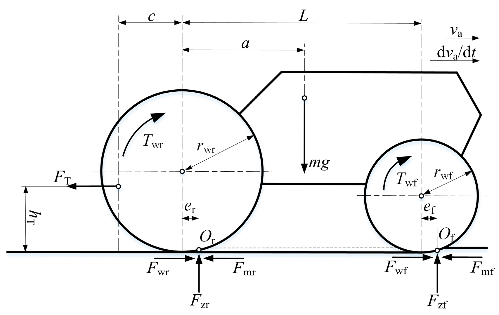
2.2.1. Traction Dynamics Model
2.2.2. Four-Wheel Drive Wheel–Soil Interaction Model
2.3. Drive Motor Model
2.4. Fuel Cell Model
2.5. Battery Model
2.6. Supercapacitor Model
3. EMSs
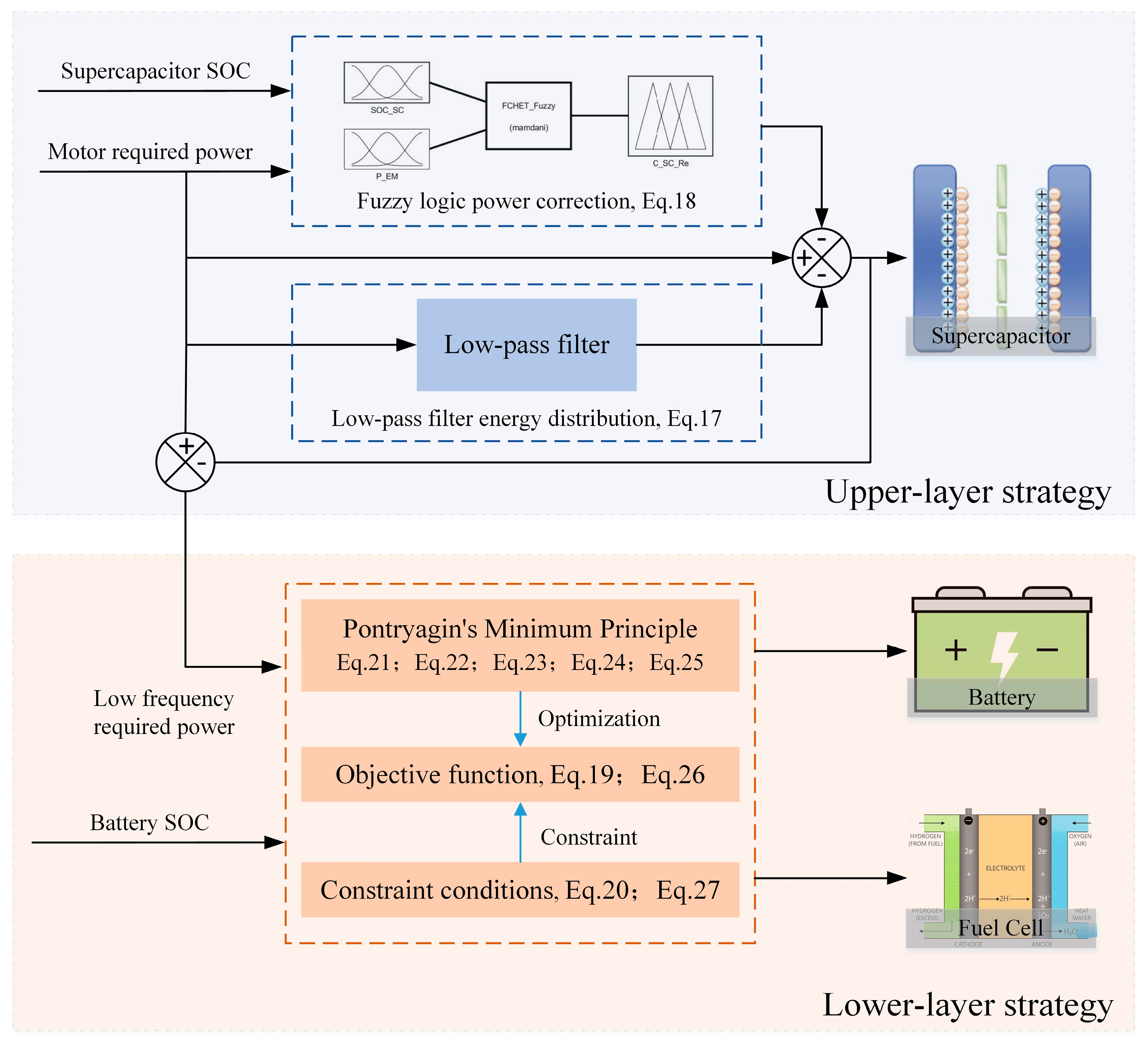
3.1. HIO
3.1.1. Upper-Layer Strategy
3.1.2. Lower-Layer Strategy
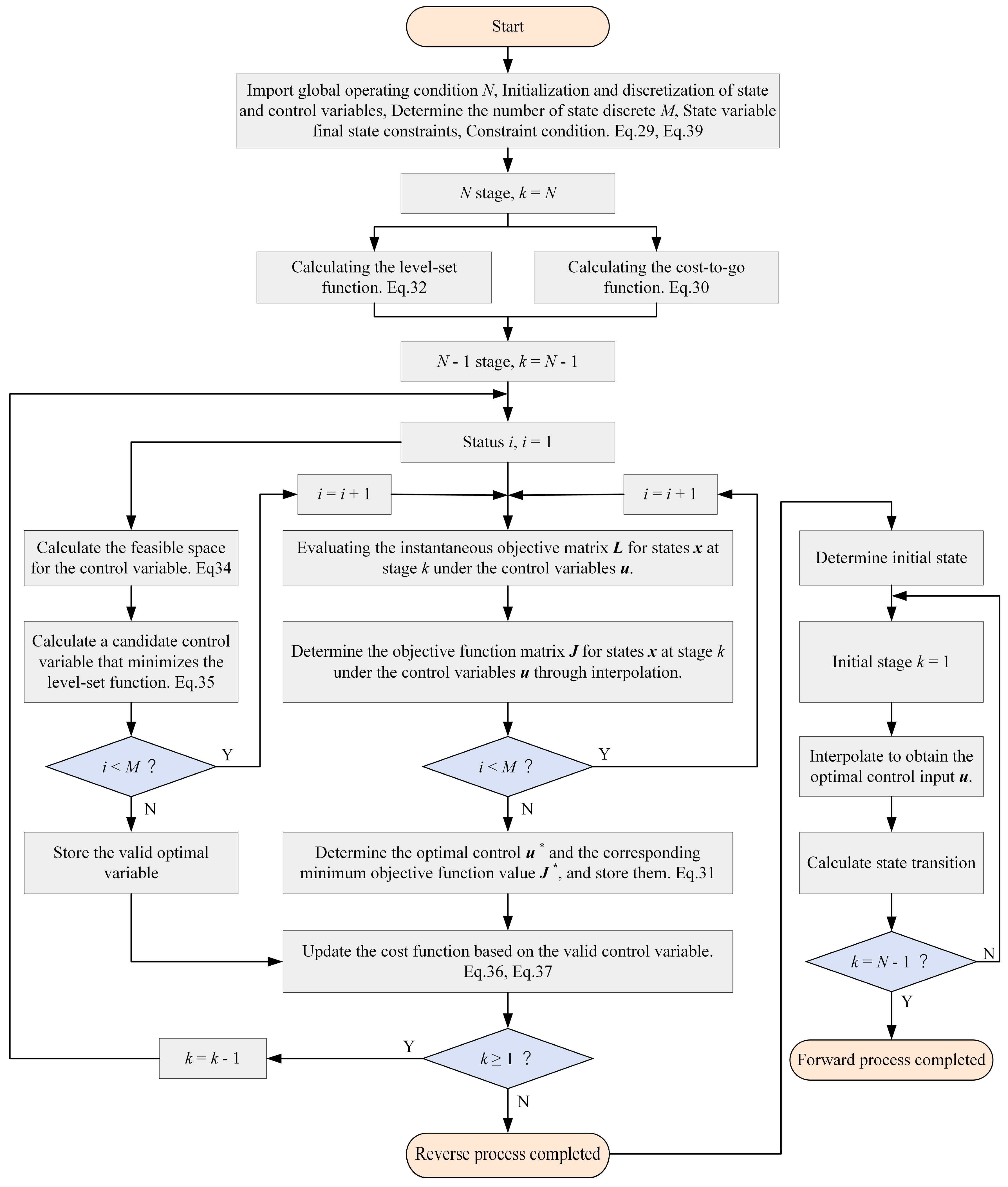
3.2. MDDP-FSC
- The cost-to-go function J at the final time step N:
- The cost function is computed recursively for each time step k from N − 1 to 0.
- The level set function I at the final time step N:where h(x) is represented by the target set T.
- The level set function is computed recursively for each time step k from N − 1 to 1.
- For each grid point xi, find a set of control variables such that the system’s iterative trajectory at the next time step will be located within the feasible space of the control variables calculated using backward iteration.And find a candidate control variable that minimizes the level set function.
- Calculate the optimal cost based on the optimal candidate control variable. Update the optimal cost according to the following rule if and only if there is at least one valid candidate control variable .
4. Simulation and Validation
4.1. HIL Test Platform
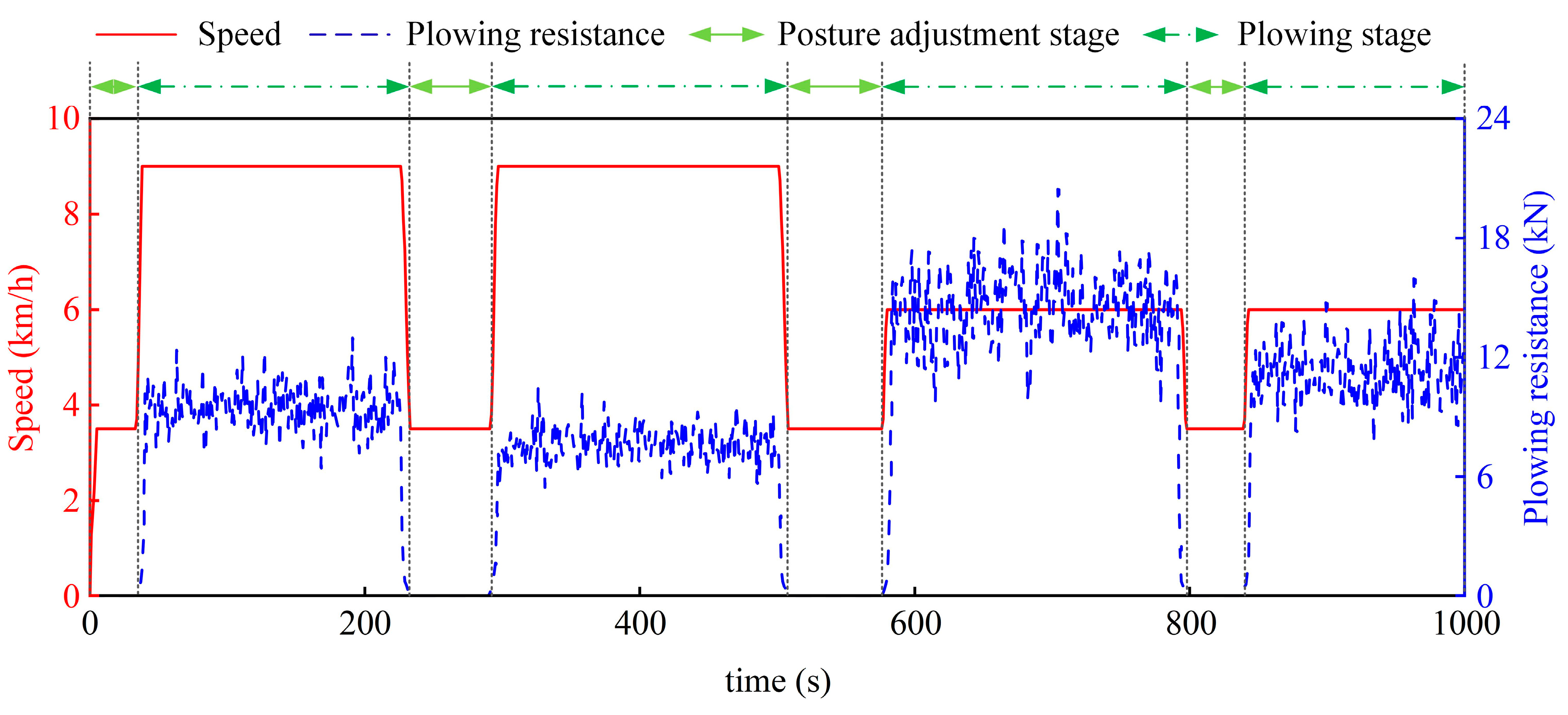
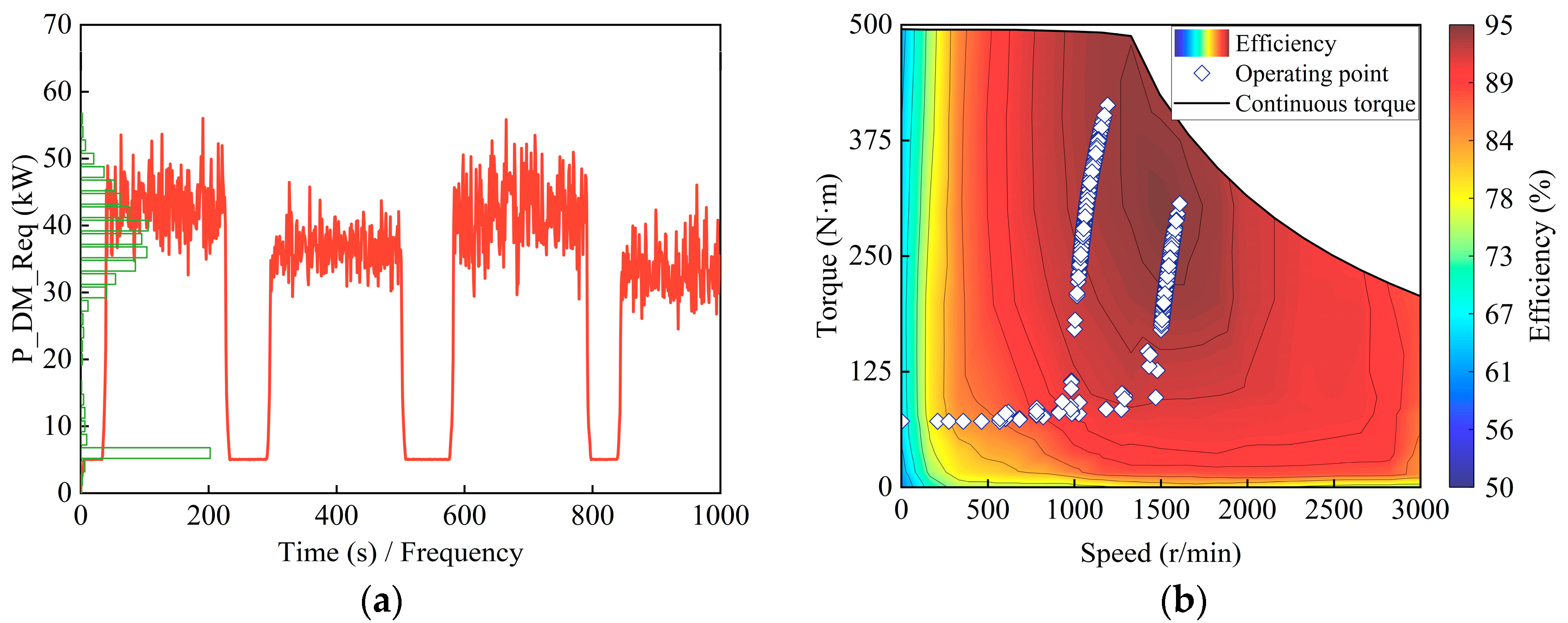
4.2. Operation Load
4.3. Feasibility Analysis
4.4. Robustness Analysis
4.5. Assessment and Potential Analysis
5. Conclusions
- Based on the tractor’s operational load characteristics, this paper designs an FCHET energy source configuration that utilizes the fuel cell for stable power, the supercapacitor for dynamic power, and the battery as an auxiliary energy source to improve fuel cell efficiency. Additionally, models for longitudinal dynamics and the energy source system were developed.
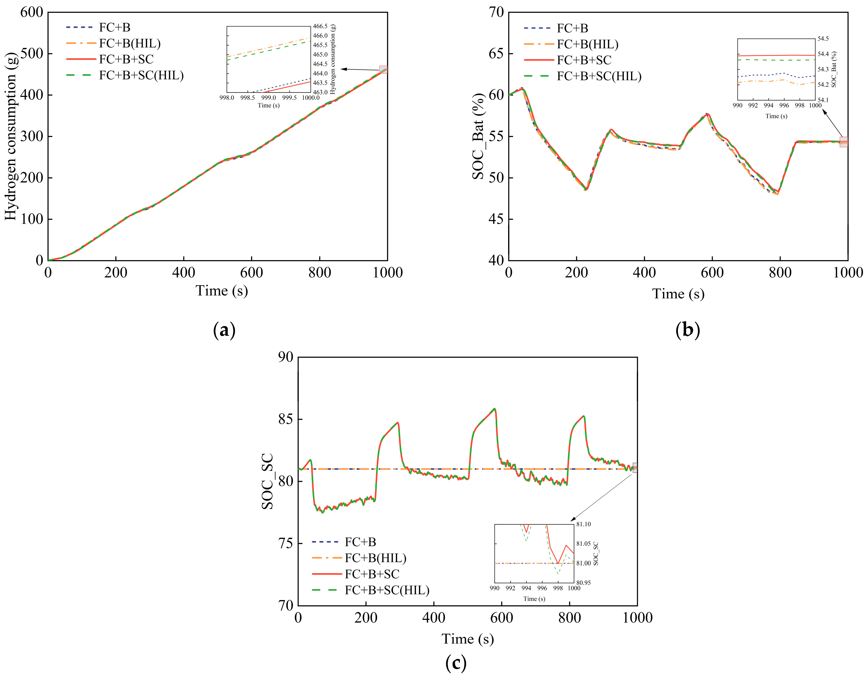
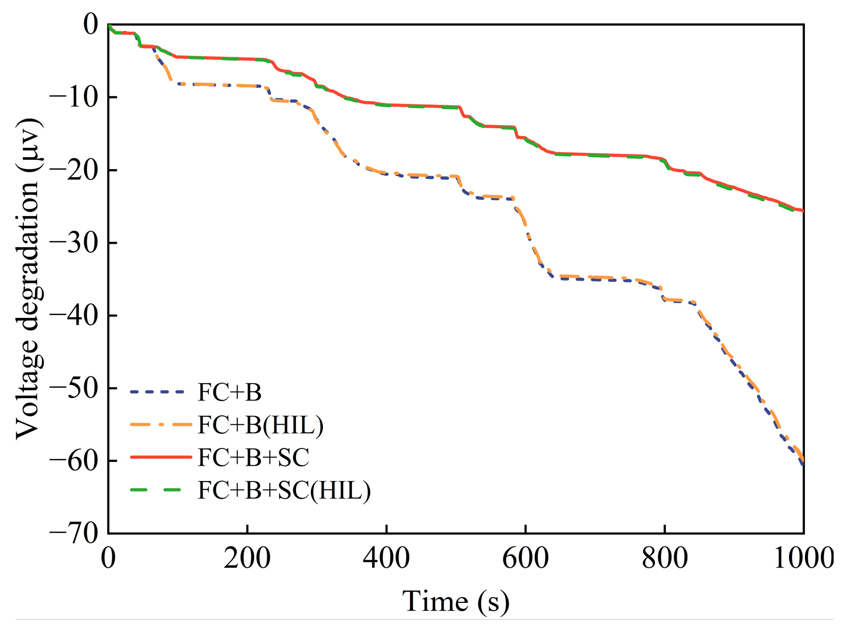
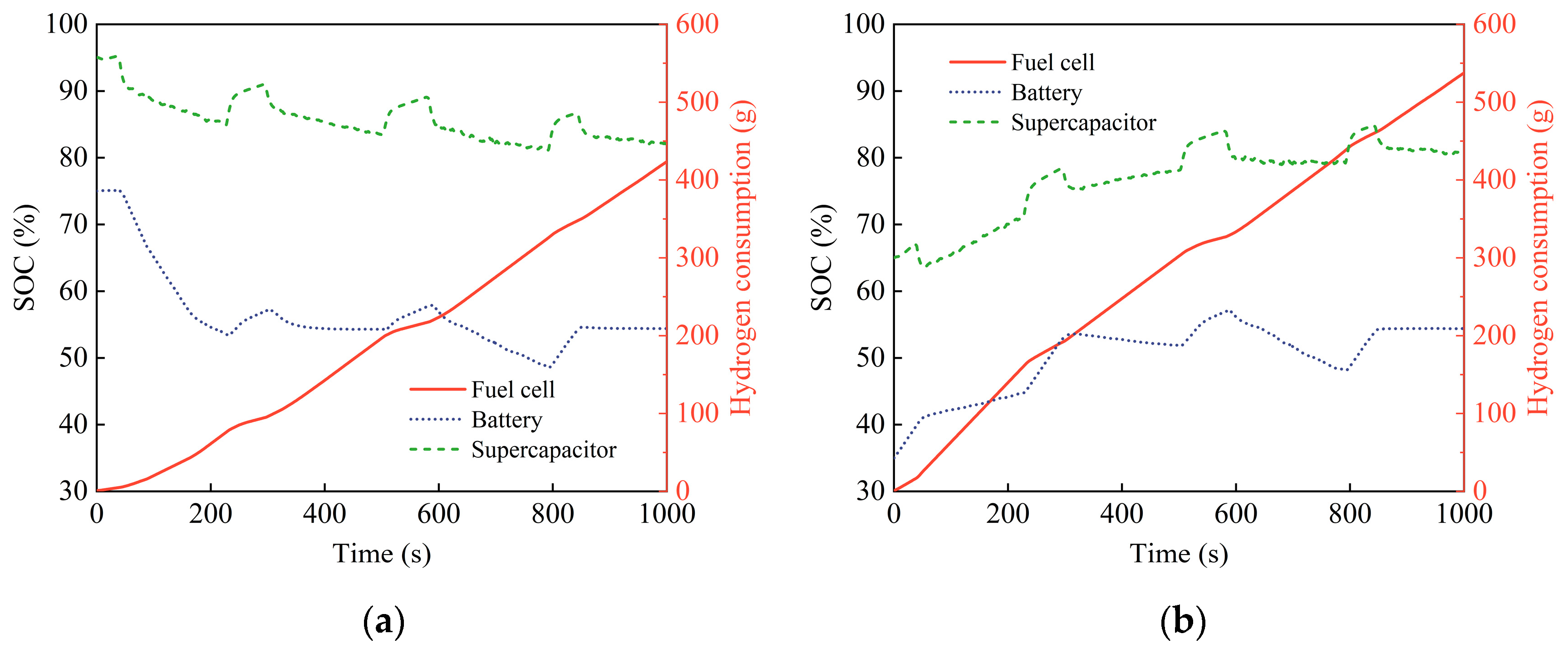
- To overcome the challenges of coordinating multi-energy source characteristics and suboptimal power distribution efficiency, this paper proposes an HIO-based EMS. The upper-layer strategy utilizes a low-pass filter to split the drive motor power into high- and low-frequency components, employing the supercapacitor to handle the high-frequency dynamic power. A fuzzy logic-based supercapacitor power regulator is implemented to ensure that the supercapacitor’s SOC remains within an appropriate range during different stages of tractor operation. The lower-layer strategy allocates low-frequency stable power based on the principle of minimizing equivalent consumption. A HIL simulation platform is developed to validate the feasibility of the proposed EMS. Simulations were conducted on different FCHET configurations under plowing conditions. Simulation results show that the addition of supercapacitors effectively mitigates the load change cycling stress on the fuel cell and the charge–discharge cycling stress on the battery, thereby improving their lifespans. Additionally, the average efficiency of fuel cell power distribution is enhanced, resulting in improved energy consumption. Moreover, the system maintains reasonable charge levels for both the battery and supercapacitor under different initial SOC conditions.
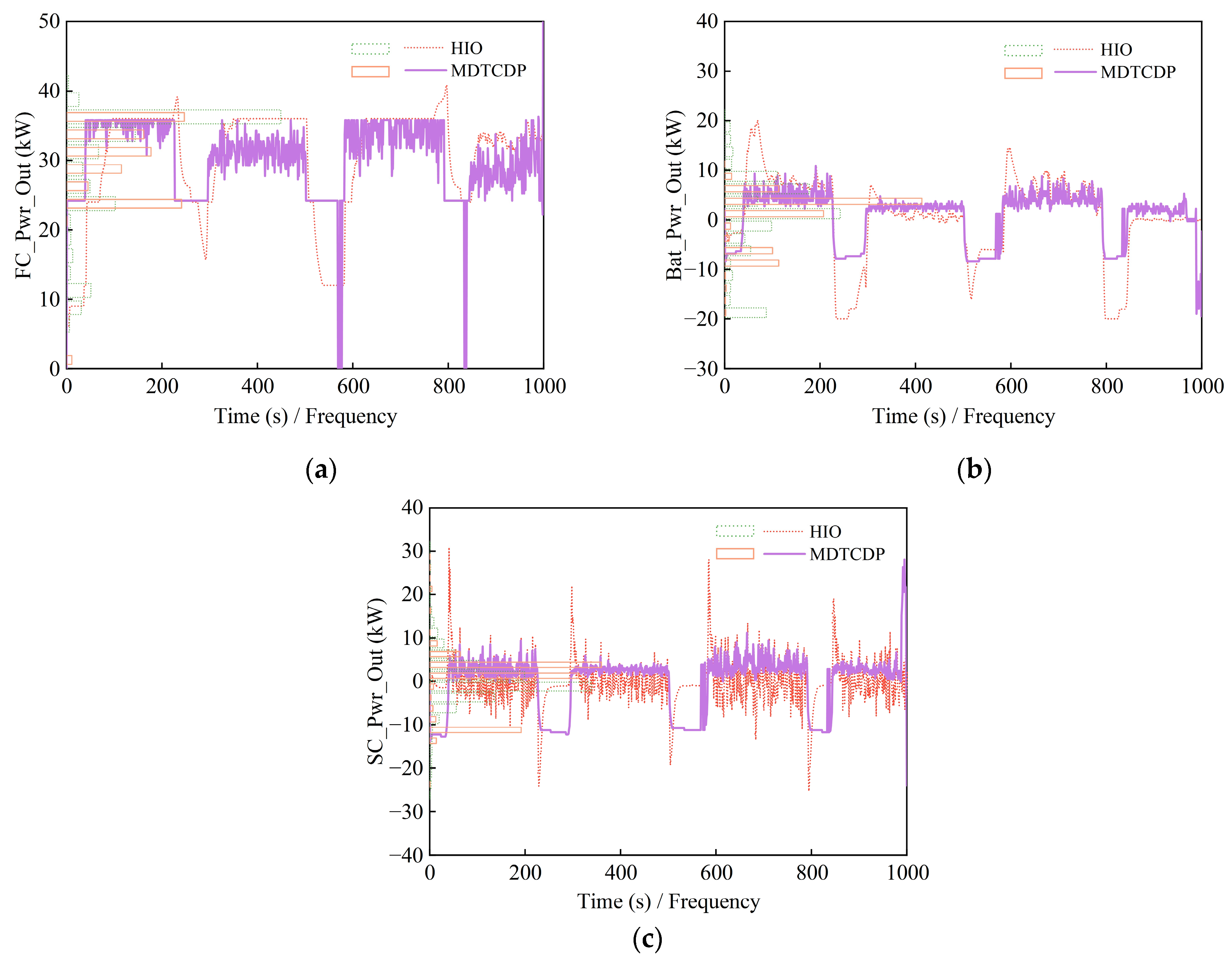
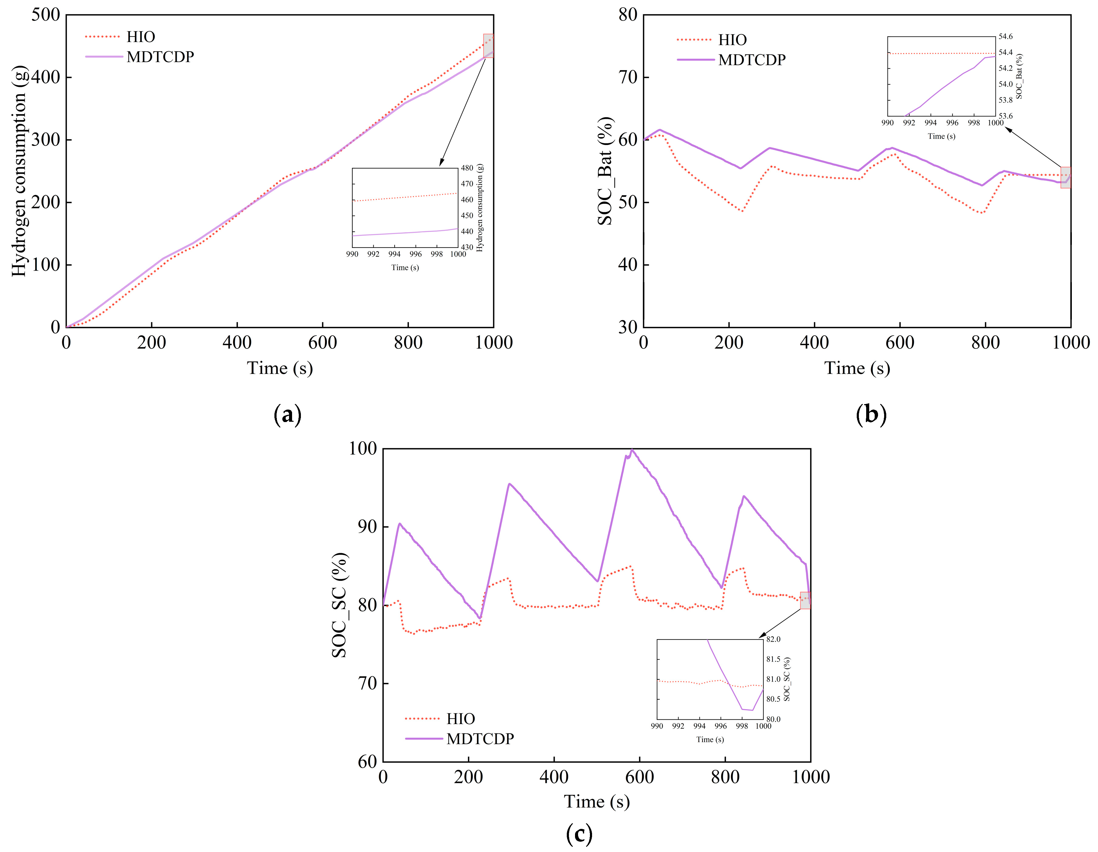
- To further evaluate the superiority of the proposed EMS and explore the global optimal energy consumption of multi-energy source FCHETs, this paper proposes an MDDP-FSC-based EMS. Simulation results indicate that, with identical initial SOC values and negligible final SOC differences between the two EMSs, the proposed EMS achieves a hydrogen consumption level of 95.20% compared to the MDDP-FSC-based EMS. This approach employs a constrained terminal state boundary solution method, effectively reducing the impact of terminal SOC differences on the comparative evaluation of control strategy superiority. Additionally, the results from the MDDP-FSC-based EMS provide new insights for future research on FCHET EMS.
Author Contributions
Funding
Data Availability Statement
Acknowledgments
Conflicts of Interest
References
- Mocera, F.; Somà, A.; Martelli, S.; Martini, V. Trends and Future Perspective of Electrification in Agricultural Tractor-Implement Applications. Energies 2023, 16, 6601. [Google Scholar] [CrossRef]
- Ali, D.; de Castro, R.; Ehsani, R.; Vougioukas, S.; Wei, P. Unlocking the Potential of Electric and Hybrid Tractors via Sensitivity and Techno-Economic Analysis. Appl. Energy 2024, 377, 124545. [Google Scholar] [CrossRef]
- Gonzalez-de-Soto, M.; Emmi, L.; Benavides, C.; Garcia, I.; Gonzalez-de-Santos, P. Reducing Air Pollution with Hybrid-Powered Robotic Tractors for Precision Agriculture. Biosyst. Eng. 2016, 143, 79–94. [Google Scholar] [CrossRef]
- Pascuzzi, S.; Łyp-Wrońska, K.; Gdowska, K.; Paciolla, F. Sustainability Evaluation of Hybrid Agriculture-Tractor Powertrains. Sustainability 2024, 16, 1184. [Google Scholar] [CrossRef]
- Liu, W.; Yang, R.; Li, L.; Zhao, C.; Li, G. Energy and Environmental Evaluation and Comparison of a Diesel-Electric Hybrid Tractor, a Conventional Tractor, and a Hillside Mini-Tiller Using the Life Cycle Assessment Method. J. Cleaner Prod. 2024, 469, 143232. [Google Scholar] [CrossRef]
- Jeon, H.-H.; Baek, S.-Y.; Baek, S.-M.; Choi, J.-Y.; Kim, Y.-S.; Kim, W.-S.; Kim, Y.-J. Efficiency Analysis of Powertrain for Internal Combustion Engine and Hydrogen Fuel Cell Tractor According to Agricultural Operations. Sensors 2024, 24, 5494. [Google Scholar] [CrossRef] [PubMed]
- Oladosu, T.L.; Pasupuleti, J.; Kiong, T.S.; Koh, S.P.J.; Yusaf, T. Energy Management Strategies, Control Systems, and Artificial Intelligence-Based Algorithms Development for Hydrogen Fuel Cell-Powered Vehicles: A Review. Int. J. Hydrogen Energy 2024, 61, 1380–1404. [Google Scholar] [CrossRef]
- Zhao, X.; Wang, L.; Zhou, Y.; Pan, B.; Wang, R.; Wang, L.; Yan, X. Energy Management Strategies for Fuel Cell Hybrid Electric Vehicles: Classification, Comparison, and Outlook. Energy Convers. Manag. 2022, 270, 116179. [Google Scholar] [CrossRef]
- Li, X.; Ye, T.; Meng, X.; He, D.; Li, L.; Song, K.; Jiang, J.; Sun, C. Advances in the Application of Sulfonated Poly(Ether Ether Ketone) (SPEEK) and Its Organic Composite Membranes for Proton Exchange Membrane Fuel Cells (PEMFCs). Polymers 2024, 16, 2840. [Google Scholar] [CrossRef] [PubMed]
- Liu, M.; Li, Y.; Xu, L.; Wang, Y.; Zhao, J. General Modeling and Energy Management Optimization for the Fuel Cell Electric Tractor with Mechanical Shunt Type. Comput. Electron. Agric. 2023, 288, 129874. [Google Scholar] [CrossRef]
- Li, X.; Zhang, M.; Yan, X.; Liu, M.; Xu, L. Power Allocation Strategy for Fuel Cell Distributed Drive Electric Tractor Based on Adaptive Multi-Resolution Analysis Theory. Energy 2023, 284, 129350. [Google Scholar] [CrossRef]
- Li, Q.; Chen, W.; Zhang, N.; Luo, Z.; Chen, B. Dynamic Response Characteristics of Proton Exchange Membrane Fuel Cell During Transient Loading: An Experiment Study. Int. J. Hydrogen Energy 2024, 92, 1–13. [Google Scholar] [CrossRef]
- Yang, Q.; Gao, B.; Xiao, G.; Jin, D. Dynamic Response Characteristics and Water-Gas-Heat Synergistic Transport Mechanism of Proton Exchange Membrane Fuel Cell During Transient Loading. Energy 2024, 302, 131852. [Google Scholar] [CrossRef]
- Das, H.S.; Tan, C.W.; Yatim, A.H.M. Fuel Cell Hybrid Electric Vehicles: A Review on Power Conditioning Units and Topologies. Renew. Sustain. Energy Rev. 2017, 76, 268–291. [Google Scholar] [CrossRef]
- Teng, T.; Zhang, X.; Dong, H.; Xue, Q. A Comprehensive Review of Energy Management Optimization Strategies for Fuel Cell Passenger Vehicle. Int. J. Hydrogen Energy 2020, 45, 20293–20303. [Google Scholar] [CrossRef]
- Berriri, M.; Chevrel, P.; Lefebvre, D.; Yagoubi, M. The Influence of Soil Physical Properties on the Load Factor for Agricultural Tractors in Different Paddy Fields. Agriculture 2023, 13, 2073. [Google Scholar] [CrossRef]
- Yang, M.; Sun, X.; Deng, X.; Lu, Z.; Wang, T. Extrapolation of Tractor Traction Resistance Load Spectrum and Compilation of Loading Spectrum Based on Optimal Threshold Selection Using a Genetic Algorithm. Agriculture 2023, 13, 1133. [Google Scholar] [CrossRef]
- Ortopan, M.; Simonović, V.; Tasić, N.; Veg, E.; Zlatanović, I.; Gubeljak, N. Analyzing Site-Specific Tractor Draft Force in Different Passes During Plowing. Teh. Vjesn. 2024, 31, 228–232. [Google Scholar] [CrossRef]
- Mattetti, M.; Maraldi, M.; Lenzini, N.; Fiorati, S.; Sereni, E.; Molari, G. Outlining the Mission Profile of Agricultural Tractors through CAN-BUS Data Analytics. Comput. Electron. Agric. 2021, 184, 106078. [Google Scholar] [CrossRef]
- Hemmati, R.; Saboori, H. Emergence of Hybrid Energy Storage Systems in Renewable Energy and Transport Applications—A Review. Renew. Sustain. Energy Rev. 2016, 65, 11–23. [Google Scholar] [CrossRef]
- Shen, Y.; Xie, J.; He, T.; Yao, L.; Xiao, Y. CEEMD-Fuzzy Control Energy Management of Hybrid Energy Storage Systems in Electric Vehicles. IEEE Trans. Energy Convers. 2024, 39, 555–566. [Google Scholar] [CrossRef]
- Sun, Y.; Xia, C.; Han, J. Research on Energy Management of Fuel-Cell Electric Tractor Based on Quadratic Utility Function. J. Energy Eng. 2023, 149, 4022044. [Google Scholar] [CrossRef]
- Martini, V.; Mocera, F.; Somà, A. Numerical Investigation of a Fuel Cell-Powered Agricultural Tractor. Energies 2022, 15, 8818. [Google Scholar] [CrossRef]
- Yang, H.; Sun, Y.; Xia, C.; Zhang, H. Research on Energy Management Strategy of Fuel Cell Electric Tractor Based on Multi-Algorithm Fusion and Optimization. Energies 2022, 15, 6389. [Google Scholar] [CrossRef]
- Bao, S.; Sun, P.; Zhu, J.; Ji, Q.; Liu, J. Improved Multi-Dimensional Dynamic Programming Energy Management Strategy for a Vehicle Power-Split Hybrid Powertrain. Energy 2022, 256, 124682. [Google Scholar] [CrossRef]
- Liu, Y.; Liang, J.; Song, J.; Ye, J. Research on Energy Management Strategy of Fuel Cell Vehicle Based on Multi-Dimensional Dynamic Programming. Energies 2022, 15, 5190. [Google Scholar] [CrossRef]
- Quan, R.; Guo, H.; Li, X.; Zhang, J.; Chang, Y. A Real-Time Energy Management Strategy for Fuel Cell Vehicle Based on Pontryagin’s Minimum Principle. iScience 2024, 27, 109473. [Google Scholar] [CrossRef] [PubMed]
- Wang, Z.; Wei, H.; Xiao, G.; Zhang, Y. Real-Time Energy Management Strategy for a Plug-in Hybrid Electric Bus Considering the Battery Degradation. Energy Convers. Manag. 2022, 268, 116053. [Google Scholar] [CrossRef]
- Ding, N.; Prasad, K.; Lie, T.T. Design of a Hybrid Energy Management System Using Designed Rule-Based Control Strategy and Genetic Algorithm for the Series-Parallel Plug-in Hybrid Electric Vehicle. Int. J. Energy Res. 2021, 45, 1627–1644. [Google Scholar] [CrossRef]
- Zhu, Z.; Zhang, Y.; Zhang, H.; Wang, D.; Chen, L. Equivalent Consumption Minimization Strategy Based on Global Optimization of Equivalent Factor for Hybrid Tractor. Sci. Rep. 2024, 14, 12911. [Google Scholar] [CrossRef]
- Zhao, Y.; Xu, L.; Zhao, C.; Xu, H.; Yan, X. Research on Energy Management Strategy for Hybrid Tractors Based on DP-MPC. Energies 2024, 17, 3924. [Google Scholar] [CrossRef]
- Varlese, C.; Ferrara, A.; Hametner, C.; Hofmann, P. Experimental Validation of a Predictive Energy Management Strategy for Agricultural Fuel Cell Electric Tractors. Int. J. Hydrogen Energy 2024, 77, 1–14. [Google Scholar] [CrossRef]
- Zhang, J.; Shi, M.; Liu, M.; Li, H.; Zhao, B.; Yan, X. Dual-Source Cooperative Optimized Energy Management Strategy for Fuel Cell Tractor Considering Drive Efficiency and Power Allocation. Agriculture 2024, 14, 1455. [Google Scholar] [CrossRef]
- Li, Y.; Liu, M.; Wang, Y.; Xu, L.; Lei, S. Energy Management Optimization and Validation of a Hydrogen Fuel Cell-Powered Agricultural Tractor Based on Hierarchical Dynamic Programming. IEEE Access 2024, 288, 21382–21401. [Google Scholar] [CrossRef]
- Martini, V.; Mocera, F.; Somà, A. Design and Experimental Validation of a Scaled Test Bench for the Emulation of a Hybrid Fuel Cell Powertrain for Agricultural Tractors. Appl. Sci. 2023, 13, 8582. [Google Scholar] [CrossRef]
- Lin, X.; Zhou, Q.; Tu, J.; Xu, X.; Xie, L. Self-Learning Markov Prediction Algorithm Based Aging-Oriented Gradient Drop Power Control Strategy for the Transient Modes of Fuel Cell Hybrid Electric Vehicles. Appl. Energy 2024, 376, 124198. [Google Scholar] [CrossRef]
- Wu, J.; Zhang, Y.; Ruan, J.; Liang, Z.; Liu, K. Rule and Optimization Combined Real-Time Energy Management Strategy for Minimizing Cost of Fuel Cell Hybrid Electric Vehicles. Energy 2023, 285, 129442. [Google Scholar] [CrossRef]
- Viji, D.; Dhanka, S.; M.B., B.; Thomas, M. Hybrid STO- IWGAN Method Based Energy Optimization in Fuel Cell Electric Vehicles. Energy Convers. Manag. 2024, 305, 118249. [Google Scholar] [CrossRef]
- Wu, J.; He, H.; Peng, J.; Li, Y.; Li, Z. Continuous Reinforcement Learning of Energy Management with Deep Q Network for a Power Split Hybrid Electric Bus. Appl. Energy 2018, 222, 799–811. [Google Scholar] [CrossRef]
- Ahmadi, P.; Raeesi, M.; Changizian, S.; Teimouri, A.; Khoshnevisan, A. Lifecycle Assessment of Diesel, Diesel-Electric and Hydrogen Fuel Cell Transit Buses with Fuel Cell Degradation and Battery Aging Using Machine Learning Techniques. Energy 2022, 259, 125003. [Google Scholar] [CrossRef]
- Ren, X.; Ye, J.; Xie, L.; Lin, X. Battery Longevity-Conscious Energy Management Predictive Control Strategy Optimized by Using Deep Reinforcement Learning Algorithm for a Fuel Cell Hybrid Electric Vehicle. Energy 2024, 286, 129344. [Google Scholar] [CrossRef]
- Wang, Z.; Zhang, S.; Luo, W.; Xu, S. Deep Reinforcement Learning with Deep-Q-Network Based Energy Management for Fuel Cell Hybrid Electric Truck. Energy 2024, 306, 132531. [Google Scholar] [CrossRef]
- Tiwari, V.K.; Pandey, K.P.; Pranav, P.K. A Review on Traction Prediction Equations. J. Terramech. 2010, 47, 191–199. [Google Scholar] [CrossRef]
- Roşca, R.; Cârlescu, P.; Ţenu, I.; Vlahidis, V.; Perşu, C. The Improvement of a Traction Model for Agricultural Tire–Soil Interaction. Agriculture 2022, 12, 2035. [Google Scholar] [CrossRef]
- Meng, X.; Sun, C.; Mei, J.; Tang, X.; Hasanien, H.M.; Jiang, J.; Fan, F.; Song, K. Fuel Cell Life Prediction Considering the Recovery Phenomenon of Reversible Voltage Loss. J. Power Sources 2024, 625, 235634. [Google Scholar] [CrossRef]
- Tang, X.; Shi, L.; Zhang, Y.; Li, B.; Xu, S.; Song, Z. Degradation Adaptive Energy Management Strategy for FCHEV Based on the Rule-DDPG Method: Tailored to the Current SOH of the Powertrain. IEEE Trans. Transp. Electrific. 2024, 1. early access. [Google Scholar] [CrossRef]
- Tang, X.; Shi, L.; Li, M.; Xu, S.; Sun, C. Health State Estimation and Long-Term Durability Prediction for Vehicular PEM Fuel Cell Stacks Under Dynamic Operational Conditions. IEEE Trans. Power Electron. 2024, 40, 4498–4509. [Google Scholar] [CrossRef]
- Zhang, R.; Li, X.; Sun, C.; Yang, S.; Tian, Y.; Tian, J. State of Charge and Temperature Joint Estimation Based on Ultrasonic Reflection Waves for Lithium-Ion Battery Applications. Batteries 2023, 9, 335. [Google Scholar] [CrossRef]
- Ahmadi, S.; Bathaee, S.M.T.; Hosseinpour, A.H. Improving Fuel Economy and Performance of a Fuel-Cell Hybrid Electric Vehicle (Fuel-Cell, Battery, and Ultra-Capacitor) Using Optimized Energy Management Strategy. Energy Convers. Manag. 2018, 160, 74–84. [Google Scholar] [CrossRef]
- Sundström, O.; Ambühl, D.; Guzzella, L. On Implementation of Dynamic Programming for Optimal Control Problems with Final State Constraints. Oil Gas Sci. Technol. Rev. Inst. Fr. Pét. 2010, 65, 91–102. [Google Scholar] [CrossRef]
- Elbert, P.; Ebbesen, S.; Guzzella, L. Implementation of Dynamic Programming for N-Dimensional Optimal Control Problems with Final State Constraints. IEEE Trans. Control Syst. Technol. 2013, 21, 924–931. [Google Scholar] [CrossRef]
- Liu, M.; Xu, L.; Zhou, Z. Design of a Load Torque Based Control Strategy for Improving Electric Tractor Motor Energy Conversion Efficiency. Math. Probl. Eng. 2016, 2016, 1–14. [Google Scholar] [CrossRef]


| Components | Parameters/Unit | Value |
|---|---|---|
| Vehicle | Tractor mass/kg | 4010 |
| Maximum traction force/kN | 18.8 | |
| Gearbox ratio | [1.8 0.8] | |
| Speed range/(km·h−1) | 0~35 | |
| Fuel cell | Type | PEMFC |
| Net power/kW | 70 | |
| Battery | Rated capacity/Ah | 15 |
| Rated voltage/V | 259 | |
| Supercapacitor | Capacitance/F | 200 |
| Rated voltage/V | 168 | |
| Internal resistance/Ω | 0.05 | |
| Drive motor | Rated power/kW | 66 |
| Rated torque/Nm | 490 | |
| Rated speed/(r·min−1) | 1320 |
| C_SC_Re | SOC_SC | |||||
|---|---|---|---|---|---|---|
| NB | NS | ZE | PS | PB | ||
| P_DM | NB | PB | PB | PS | PS | ZE |
| NS | PB | PB | PS | ZE | ZE | |
| ZE | PB | PS | ZE | ZE | NS | |
| PS | PS | PS | ZE | NS | NS | |
| PB | PS | PS | NS | NS | NB | |
| Variable | Variable Name | Grid Partitioning |
|---|---|---|
| State 1 | Battery SOC | [0.3:0.005:0.8] |
| State 2 | Supercapacitor SOC | [0.6:0.005:1] |
| Control 1 | Fuel cell output power | [0:0.5:60] |
| Control 2 | Battery output power | [−20:0.5:25] |
| Control 3 | Gear number | [1,2] |
| Configuration | FC+B+SC | FC+B | FC+B+SC (HIL) | FC+B (HIL) |
|---|---|---|---|---|
| Hydrogen consumption | 463.57 g | 463.74 g | 465.72 g | 465.91 g |
| Initial battery SOC | 60% | 60% | 60% | 60% |
| Final battery SOC | 54.39% | 54.26% | 54.36% | 54.22% |
| Initial supercapacitor SOC | 81% | 81% | 81% | 81% |
| Final supercapacitor SOC | 81.02% | 81% | 81% | 81% |
| Initial SOC | High-Level | Low-Level |
|---|---|---|
| Hydrogen consumption | 423.66 g | 537.67 g |
| Initial battery SOC | 75% | 35% |
| Final battery SOC | 54.40% | 54.39% |
| Initial supercapacitor SOC | 95% | 65% |
| Final supercapacitor SOC | 82.03% | 80.73% |
| EMS | HIO | MDDP-FSC | Percentage Achieved |
|---|---|---|---|
| Hydrogen consumption | 464.23 g | 441.95 g | 95.20% |
| Initial battery SOC | 60% | 60% | - |
| Final battery SOC | 54.39% | 54.35% | 100.07% |
| Initial supercapacitor SOC | 80% | 80% | - |
| Final supercapacitor SOC | 80.84% | 80.76% | 100.10% |
Disclaimer/Publisher’s Note: The statements, opinions and data contained in all publications are solely those of the individual author(s) and contributor(s) and not of MDPI and/or the editor(s). MDPI and/or the editor(s) disclaim responsibility for any injury to people or property resulting from any ideas, methods, instructions or products referred to in the content. |
© 2025 by the authors. Licensee MDPI, Basel, Switzerland. This article is an open access article distributed under the terms and conditions of the Creative Commons Attribution (CC BY) license (https://creativecommons.org/licenses/by/4.0/).
Share and Cite
Lei, S.; Li, Y.; Liu, M.; Li, W.; Zhao, T.; Hou, S.; Xu, L. Hierarchical Energy Management and Energy Saving Potential Analysis for Fuel Cell Hybrid Electric Tractors. Energies 2025, 18, 247. https://doi.org/10.3390/en18020247
Lei S, Li Y, Liu M, Li W, Zhao T, Hou S, Xu L. Hierarchical Energy Management and Energy Saving Potential Analysis for Fuel Cell Hybrid Electric Tractors. Energies. 2025; 18(2):247. https://doi.org/10.3390/en18020247
Chicago/Turabian StyleLei, Shenghui, Yanying Li, Mengnan Liu, Wenshuo Li, Tenglong Zhao, Shuailong Hou, and Liyou Xu. 2025. "Hierarchical Energy Management and Energy Saving Potential Analysis for Fuel Cell Hybrid Electric Tractors" Energies 18, no. 2: 247. https://doi.org/10.3390/en18020247
APA StyleLei, S., Li, Y., Liu, M., Li, W., Zhao, T., Hou, S., & Xu, L. (2025). Hierarchical Energy Management and Energy Saving Potential Analysis for Fuel Cell Hybrid Electric Tractors. Energies, 18(2), 247. https://doi.org/10.3390/en18020247