Article

Feasibility Study of Flywheel Mitigation Controls Using Hamiltonian-Based Design for E3 High-Altitude Electromagnetic Pulse Events

by
Connor A. Lehman
1,*,
Rush D. Robinett III
2,
David G. Wilson
1 and
Wayne W. Weaver
2
1
Sandia National Labs, 1515 Eubank Blvd. SE, Albuquerque, NM 87122, USA
2
Department of Mechanical and Aerospace Engineering, Michigan Technical University, 1400 Townsend Dr., Houghton, MI 49931, USA
*
Author to whom correspondence should be addressed.
Energies 2025, 18(19), 5294; https://doi.org/10.3390/en18195294
Submission received: 22 August 2025 / Revised: 2 October 2025 / Accepted: 3 October 2025 / Published: 7 October 2025

Abstract

This paper explores the feasibility of implementing a flywheel energy storage system designed to generate voltage for the purpose of mitigating current flow through the transformer neutral path to ground, which is induced by a high-altitude electromagnetic pulse (HEMP) event. The active flywheel system presents the advantage of employing custom optimal control laws, in contrast to the conventional approach of utilizing passive blocking capacitors. A Hamiltonian-based optimal control law for energy storage is derived and integrated into models of both the transformer and the flywheel energy storage system. This Hamiltonian-based feedback control law is subsequently compared against an energy-optimal feedforward control law to validate its optimality. The analysis reveals that the required energy storage capacity is 13 Wh , the necessary power output is less than 5 kW at any given time during the insult, and the required bandwidth for the controller is around 5 Hz . These specifications can be met by commercially available flywheel devices. This methodology can be extended to other energy storage devices to ensure that their specifications adequately address the requirements for HEMP mitigation.

1. Introduction

In recent years, there has been increasing interest in mitigating the effects of high-altitude electromagnetic pulses (HEMPs) on the power grid [1,2]. A HEMP results from the detonation of a high-yield nuclear device in the Earth’s atmosphere [3]. HEMP fields can couple with conductive materials and devices, leading to significant operational challenges due to geomagnetically induced currents (GICs). The HEMP insult is conventionally categorized into three distinct time domains. The first time domain, referred to as the E 1 component, represents the most impulsive and powerful of the three components. According to IEC Standard 61000-2-9, the E 1 portion occurs within the first 0.1 μ s of the total insult waveform, exhibiting a field strength exceeding 10 kV / m [4]. Mitigation strategies for this portion of the insult typically involve the use of trip coils [5,6].
The second time component of the HEMP insult is designated as the E 2 portion, which is agreed upon to occur from the conclusion of the E 1 insult up to 1 s following the detonation of the nuclear device. The potential field strength of the E 2 component is considerably weaker than that of the E 1 portion, ranging from 1 V / m to 100 V / m . The final component, known as the E 3 portion, encompasses the total insult occurring from 1 s to 250 s post-detonation. This component is further divided into blast and heave segments, which will be elaborated upon in the System Models Section of this paper. The focus of this study is on mitigating the late-time, low-frequency portion of the HEMP insult to protect power grid transformers. The threats associated with this segment of the HEMP insult include, but are not limited to, core over-saturation, dielectric material failure, and electrical creep through insulation materials [7].
A common solution for preventing transformer magnetic core saturation during the late-time portion of a HEMP insult is the utilization of neutral path blocking capacitors [8,9]. In the presence of a DC offset, the neutral blocking capacitor behaves as an open circuit, thereby preventing a DC insult from passing through the core and out through the neutral ground. However, it is important to note that the late-time portion of the HEMP insult does not constitute a true DC signal [10]. The recent literature has demonstrated that this late-time component is sufficiently impulsive to generate system oscillations when interacting with blocking capacitors and system inductances [11]. Moreover, since capacitors function as passive integral controllers, they can lead to instability if poorly tuned [12,13].
This paper proposes an alternative approach to the design of neutral blocking devices for HEMP insult mitigation. Instead of employing a blocking capacitor, this paper explores the use of a flywheel energy storage system to generate the necessary voltage for HEMP mitigation along the neutral path of a standalone transformer. Flywheels have demonstrated potential for stabilizing the grid in the context of an increasing number of stochastic energy generation devices [14,15]. The flywheel energy storage system offers several advantages over other potential HEMP mitigation devices. As an actively controlled system, it allows for the development of custom and optimal control laws that enhance overall performance. Additionally, the maintenance costs associated with flywheel energy storage devices are relatively low over their extended lifespan [16,17,18]. Furthermore, many flywheel devices are already integrated into the power grid, facilitating the reuse of existing energy storage systems for grid stabilization, which can further reduce the costs associated with HEMP mitigation.
The flywheel operates by converting electrical power into kinetic energy for later use. Kinetic energy is stored in the form of a rotating mass and typically housed within a vacuum to minimize friction losses. During the charging phase, the flywheel functions as a motor, drawing power to apply torque to the rotor. When energy is required, the flywheel acts as a turbine, and the rotational velocity decreases as power is extracted from the energy storage system. Notably, the flywheel energy storage system offers advantages over chemical batteries, including increased power density, improved lifecycle, and the ability to release energy more rapidly than conventional battery energy storage systems. This paper outlines specifications for the application of flywheel energy storage systems in mitigating HEMP E 3 insults. This is achieved through the development of an optimal control law for energy storage utilizing Hamiltonian feedback control methods [19,20]. It is demonstrated that an energy-optimal control law can effectively prevent any current flow through the neutral path to ground by generating a commanded voltage on a bus connected to the flywheel energy storage system. Early pioneering work on generating flywheel-specific energy storage requirements to support advanced pulsed power weaponry was initially applied to next-generation Navy warships [21].
The use of flywheels provides some additional benefits to grid operators. Additional actively controlled energy storage sources may be used to improve grid stability through voltage and frequency regulation [18,22]. Additionally, flywheel energy storage systems have been shown to facilitate the penetration of renewable energy sources into the grid and provide power in down-times for stochastic energy sources on the grid [23,24]. This is in contrast to supercapacitors, such as the ABB SolidGround system, which are incapable of providing the same responses and controls that active systems, such as flywheels, are capable of providing [25,26]. The flywheel neutral blocking device would be placed along the neutral path of a transformer in lieu of a neutral blocking capacitor, such as SolidGround.
The structure of this paper is organized into six sections. Section 1 serves as the introduction, providing a high-level overview of the paper’s intent and a literature review on the topic. Section 2 introduces the system models employed in the simulations. Section 3 derives control laws and analyzes system stability using Hamiltonian methods. Section 4 presents the results obtained from the simulations. Section 5 offers a discussion and analysis of these results, including the development of an optimal feedforward controller to verify the optimality of the Hamiltonian feedback controller. Finally, Section 6 concludes the paper by summarizing the key findings.

2. System Models

This section presents three models utilized in the simulation. The first subsection introduces the E 3 HEMP insult model. The second subsection describes the per-phase transformer model employed in the analysis. The final subsection presents the flywheel/converter system, which provides the control effort u n to the per-phase transformer. It is assumed that the transformer and flywheel system couple solely with the transformer neutral voltage source u n and the flywheel output voltage bus v B .

2.1. HEMP Insult Model

A HEMP insult is characterized by three distinct time domain components. The first component, referred to as E 1 , exhibits the highest frequency and field strength. The second component, E 2 , has a lower frequency, occurs over a longer duration than the E 1 portion, and possesses a slightly weaker peak field strength. The final time component, E 3 , is further divided into two segments. The first segment is known as the blast, or E 3 A , which is described by Equation [10] as follows:
E 3 A ( t ) = α e t / β ( γ t δ t 2 )
where α = 9.5 , β = 1.4 , γ = 26 , and δ = 8.9 . The second segment is referred to as the heave, or E 3 B , with its field strength defined as
E 3 B ( t ) = α t 2 e t / γ β 3 t 3 β 3 γ + t 4 γ ( β 3 + t 3 ) 2
where α = 1.3 · 10 6 , β = 200 , and γ = 20 . The total field strength is given by
E 3 ( t ) = E 3 A ( t ) + E 3 B ( t ) ,
where E 3 A is defined in (1) and E 3 B is defined in (2).
These parameters are derived from curve fitting conducted during simulation work at Oak Ridge National Labs [10]. The waveform of the insult is depicted in Figure 1. The insult waveform defined in [10] is intentionally designed to be approximately twice the magnitude of what is conventionally defined for HEMP insult waveforms at the request of the US Department of Energy to provide a safety factor in HEMP mitigation design.
The E 3 portion of the HEMP insult is conventionally regarded as a pseudo-DC disturbance; however, this characterization is misleading. As demonstrated by Donnelly et al., the early time component of the E 3 A insult is sufficiently impulsive to induce ringing throughout a system when utilizing blocking capacitors for mitigation [11]. The heave, or E 3 B , portion occurs concurrently with the E 3 A segment and is characterized by a sufficiently low frequency that allows it to be treated as a pseudo-DC source to the grid. The field strength equations are expressed in units of V/km. The effective voltage along a transmission line is given by
V ( t ) = E 3 ( t ) · l · cos ( θ ) ,
where E 3 ( t ) is defined in (3), l is the length of the transmission line, and θ is the angle between the HEMP field and the transmission line. Longer transmission lines that are more parallel to the HEMP field will experience greater power reception from the HEMP compared to shorter lines that are more perpendicular to the insult.

2.2. Per-Phase Transformer Model

The per-phase transformer model incorporates winding losses and energy storage due to the windings, as well as core losses and a saturable magnetic core. A schematic representation of the transformer is shown in Figure 2.
The corresponding dynamic system of equations is expressed as follows in (5):
L 1 i ˙ 1 L 2 i ˙ 2 λ ˙ m = ( R 1 + R c ) R c 0 R c ( R 2 + R c ) 0 R c R c 0 i 1 i 2 λ m + v 1 u n R c i m v 2 u n R c i m R c i m
In (5), L 1 and L 2 represent the primary- and secondary-side energy storage due to winding inductance, R 1 and R 2 denote the primary- and secondary-side winding losses, R c indicates the core losses, u n is the controlled voltage source on the neutral, v 1 is the primary-side voltage, and v 2 is the secondary-side voltage, given by v 2 = i 2 R L , where R L is the resistive load connected to the transformer. The term i m represents a nonlinear current through the core and is approximated as
i m = k 1 tan ( k 2 λ m )
where k 1 = 0.0016 and k 2 = 1.2879 [11]. The corresponding plot of the current is illustrated in Figure 3.
Figure 3 demonstrates that as long as the magnetic core flux of the transformer is prevented from saturating, it operates linearly. Within the linearized (unsaturated) region, the ratio between i m and λ m is approximately 1 / 500 , indicating that L m 500 H [11], where L m represents the linearized inductance of the transformer core.

2.3. Flywheel Model

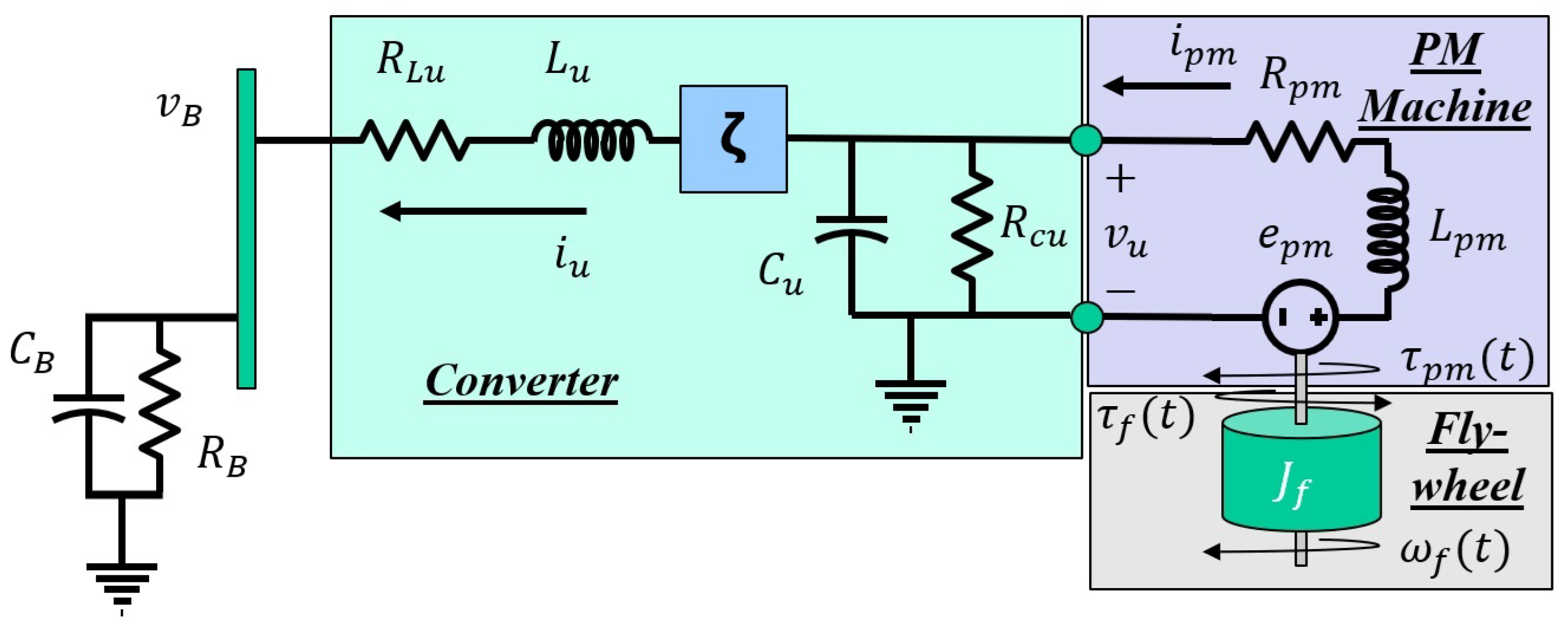
The flywheel free-body diagram, permanent magnetic (PM) machine, and converter circuit are depicted in Figure 4.
In Figure 4, ω f represents the flywheel angular velocity, τ f denotes the torque due to bearing friction in the flywheel, τ p m is the torque produced by the PM machine, v u is the voltage output from the PM machine, i p m is the current output by the PM machine, i u is the current output from the converter, ζ is the variable converter ratio, and v B is the bus voltage that is fed into Figure 2 through the u n term. The remaining parameters for the flywheel are summarized in Table 1.
The flywheel system is governed by five state equations: one for the flywheel dynamics, one for the PM machine dynamics, two for the converter dynamics, and one for the bus dynamics. The flywheel dynamics are described by
J f ω ˙ f = B ω f k t i p m .
The PM machine dynamics are given by
L p m i ˙ p m = k t ω f R p m i p m v u .
The dynamics of the converter are expressed as
C u v ˙ u = v u R c u + i p m ζ i u
and
L u i ˙ u = v B R u i u + ζ v u .
Lastly, the bus dynamics are represented as
C B v ˙ B = i u + i 1 + i 2 v B R B ,
with i 1 and i 2 are the currents through the primary and secondary windings of the per-phase transformer. The converter ratio, ζ , is constrained to 1 ζ 1 and serves as the control variable for the flywheel system. The nature of the control law will be further discussed in the next section.

3. Control Law Development

It has been demonstrated in [19,27,28] that the Hamiltonian framework can be employed to develop energy-minimized control laws and ensure system stability. For system stability, two criteria must be met [19]:
  • The Hamiltonian of the system must be positive definite about the equilibrium point.
  • The time derivative of the Hamiltonian must be negative definite about the equilibrium point.
Hamiltonian controls are developed with these criteria in mind. The Hamiltonian control law is developed here to minimize transformer magnetic core flux and minimize the energy storage requirements for this controller. This is used as a baseline for future development of other control laws that may have different control objectives. The dynamics of the per-phase transformer are described by the equations in (5). Given that the objective of the optimal control law is to maintain the transformer’s magnetic core flux within the unsaturated region, it is reasonable to assume that λ m is linear, allowing for the approximation of i m as i m λ m 500 . Consequently, (5) can be reformulated into a matrix form more conducive to the Hamiltonian construction:
M x ˙ = R x + B u + D v ,
where
M = L 1 0 0 0 L 2 0 0 0 L m , R = ( R 1 + R c ) R c R c R c ( R 2 + R c + R L ) R c R c R c R c , B = 1 1 0 , D = 1 0 0 , x = i 1 i 2 i m , u = u n ( t ) , i m λ m L m , v = v 1 0 0
The controls are developed following the formulation in [29]. The total energy of the system is expressed as
H = 1 2 x T M x .
Upon examination of the terms in M, it is evident that the Hamiltonian of the system satisfies H > 0 x 0 . Thus, the first criterion for asymptotic stability is fulfilled. However, this condition alone is insufficient for establishing stability. The time derivative of the Hamiltonian is given by
H ˙ = x T M x ˙ = x T R x < 0 x 0 .
It can be shown that R is negative definite for all positive and realizable entries. Therefore, to ensure that the second stability criterion is satisfied, the remaining terms must also be negative semi-definite. The remaining terms are set such that
x T ( B u n + D v ) = 0 .
The equation in (16) is expanded so that u n may be solved for.
u n ( i 1 + i 2 ) = v 1 i 1
By solving for u n in (17), the control law commanded by the neutral blocking device is derived as
u n = v 1 i 1 i 1 + i 2 + ϵ ,
where ϵ is a small constant introduced to avoid singularities during implementation. In the case of this paper,
ϵ = 10 3 , i 1 + i 2 0 10 3 , i 1 + i 2 < 0
This control law satisfies the criteria for asymptotic stability while minimizing the energy required to counteract the HEMP insult. The subsequent subsection will address the stability and control law for the flywheel/converter system. This u n is used to command a control output from the flywheel subsystem.
The converter ratio, ζ , shown in Figure 4 is the control variable for the flywheel subsystem. The converter in this paper is a bi-directional dual active bridge converter. This allows power to flow in either direction through the converter (and thus permits a positive or negative converter ratio) [30,31]. The converter ratio ζ is constrained such that
1 ζ 1 .
Following the work of [21], let the converter ratio control law be defined as
ζ ( t ) = K p μ ˜ + K i μ ˜ i ,
where μ ˜ = u n v b and μ ˜ ˙ i = μ ˜ . Consequentially, the system gains a state for μ ˜ i . Therefore, (9) and (10) become
C u v ˙ u = v u R c u + i p m i u ( K i μ ˜ i + K p ( u n v b ) )
and
L u i ˙ u = v B R u i u + v u ( K i μ ˜ i + K p ( u n v b ) ) ,
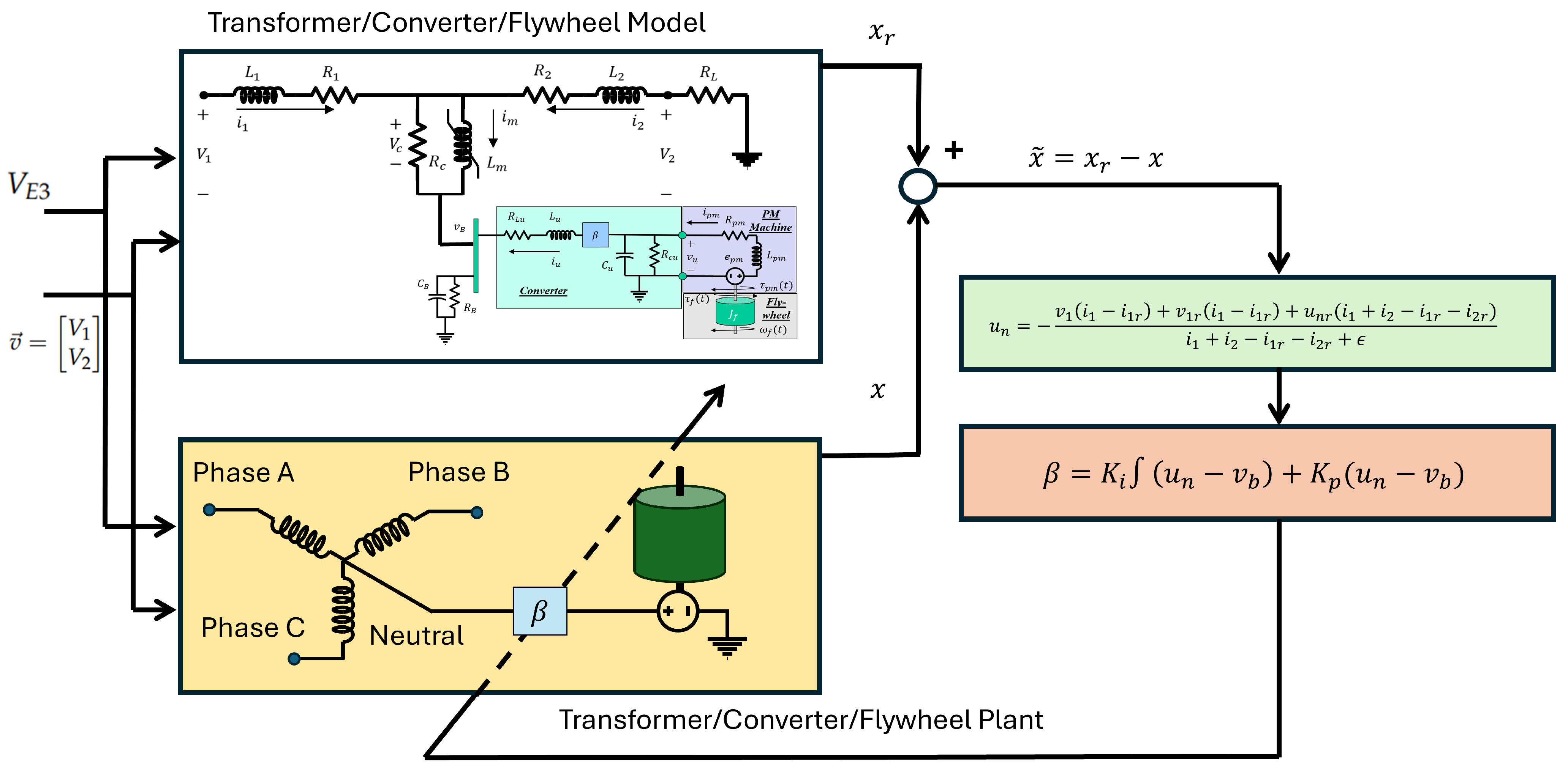
respectively. Through optimization of values, it was determined that K p = 2.5 · 10 3 and K i = 0 . These values were selected to ensure that the flywheel had significant enough bandwidth to properly respond to commanded control efforts. The full flywheel mitigation system block diagram is given in Figure 5.

4. Results

This section presents the specifications required for the neutral-blocking E 3 mitigation device. Table 2 states the required specifications for the flywheel. If the device exceeds the presented specifications, then it is a viable option for neutral path mitigation.
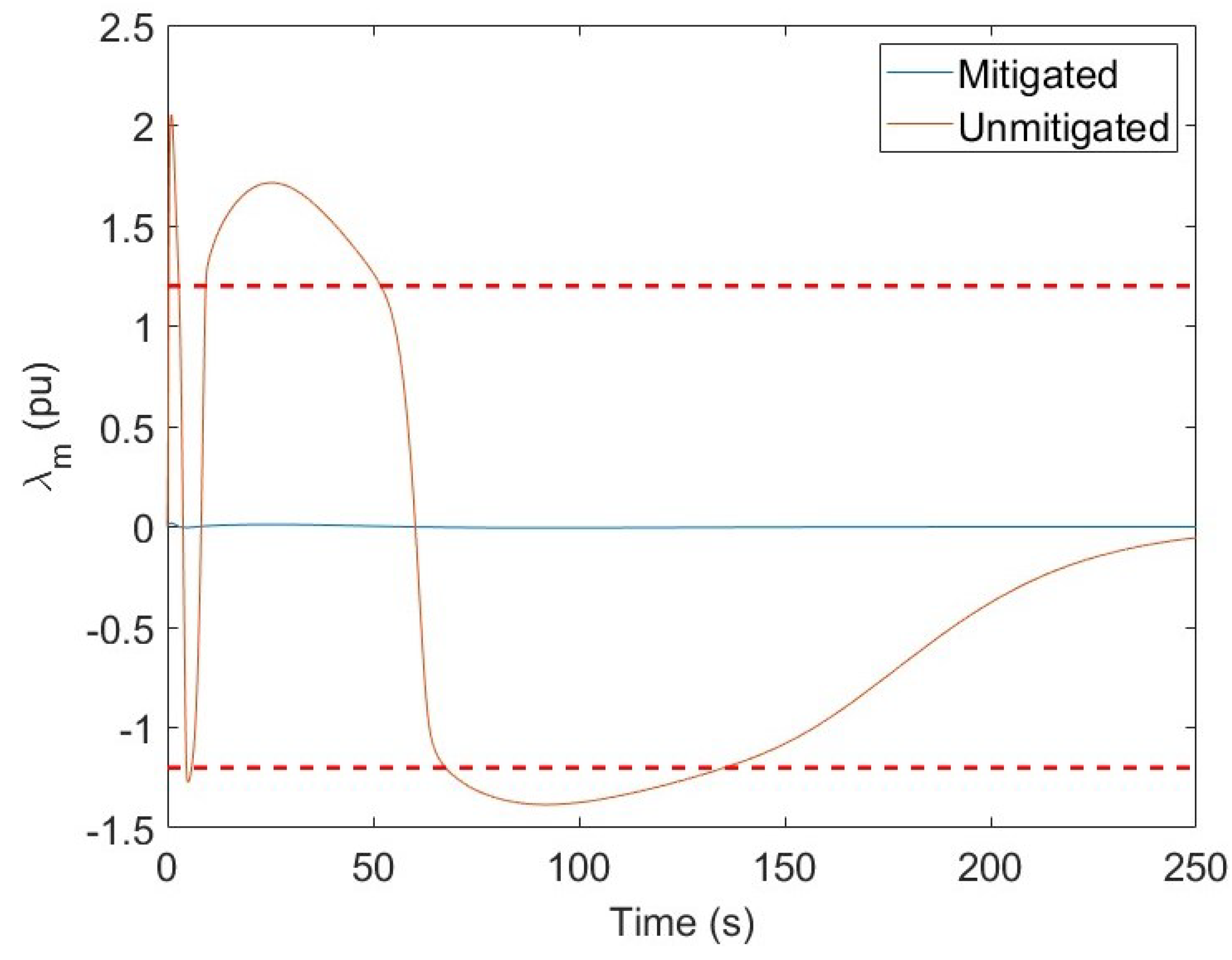
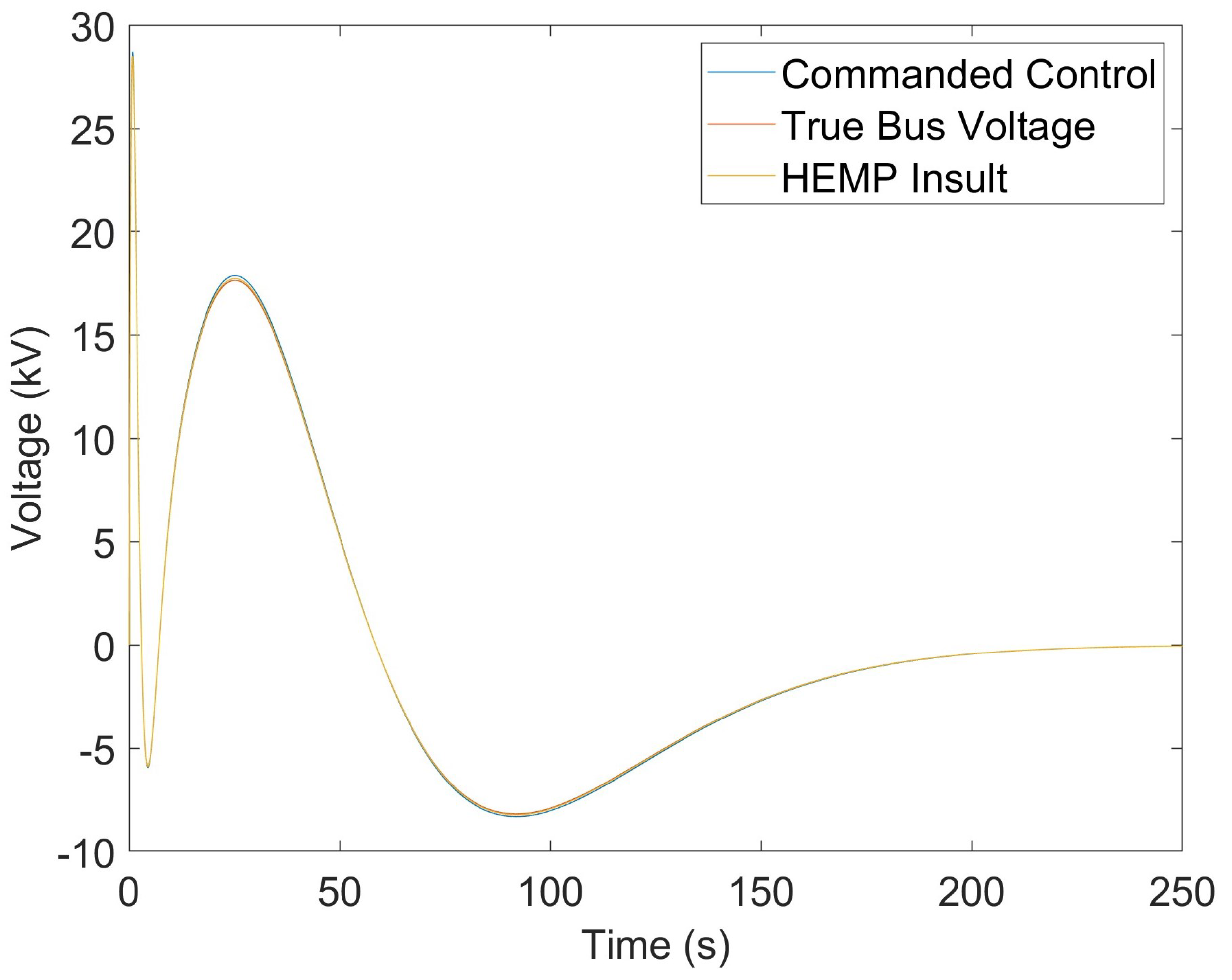
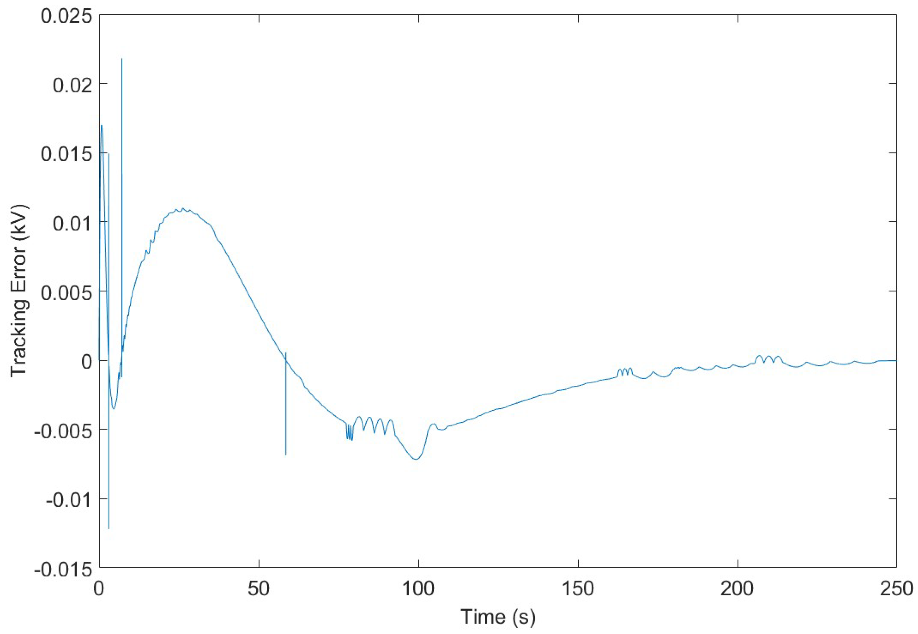
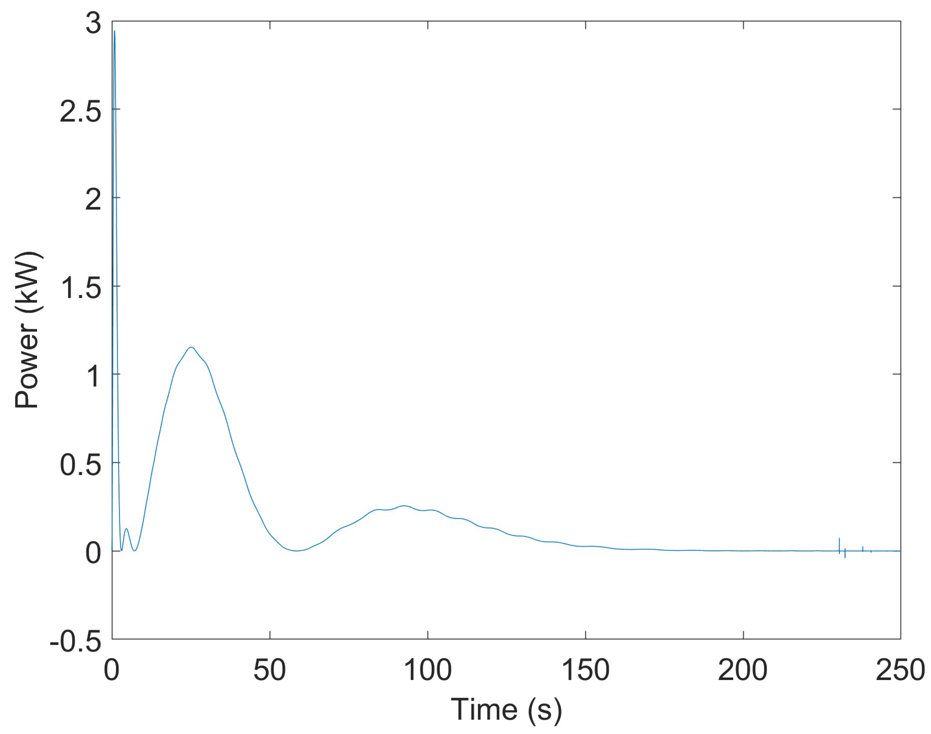
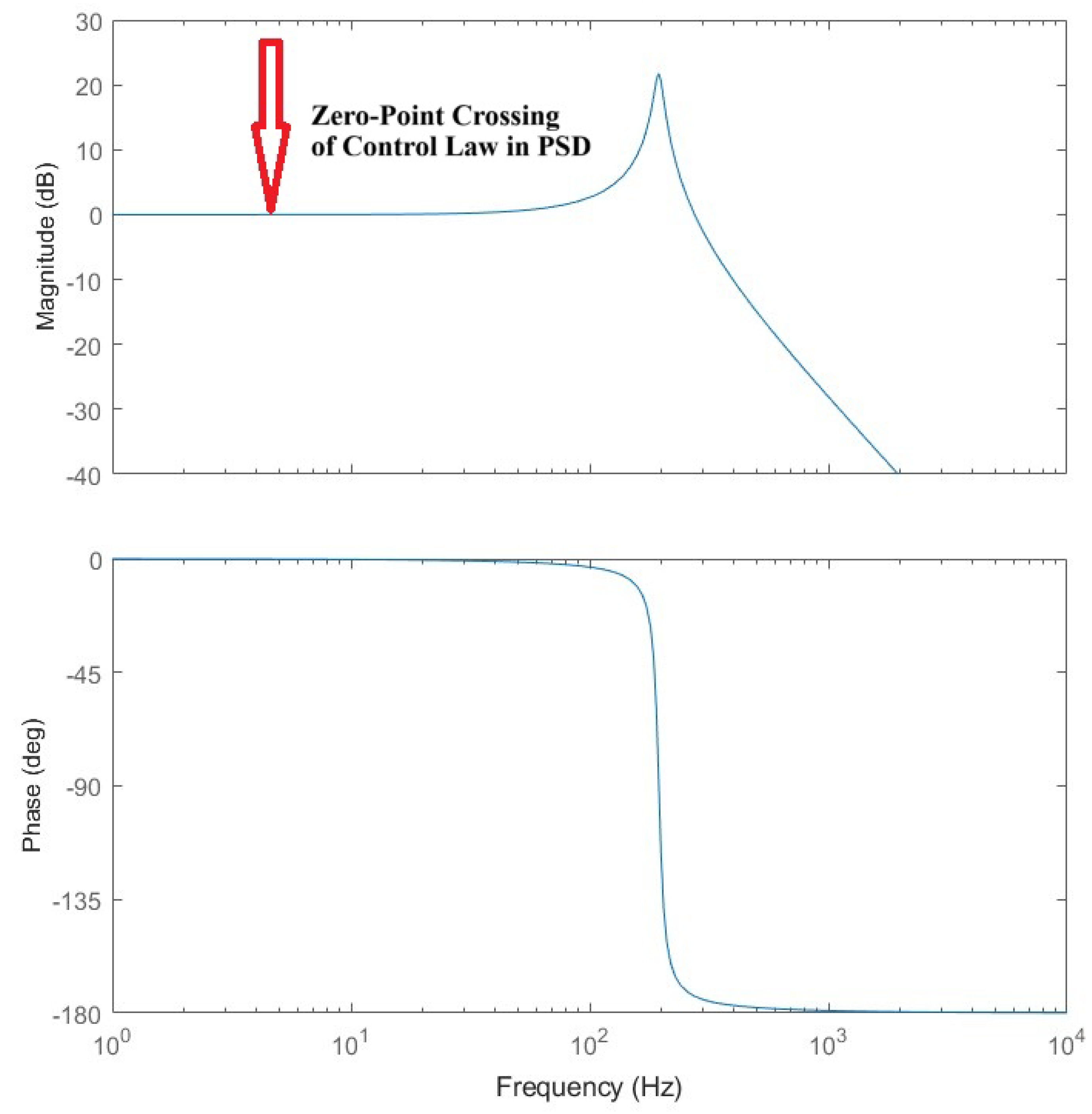
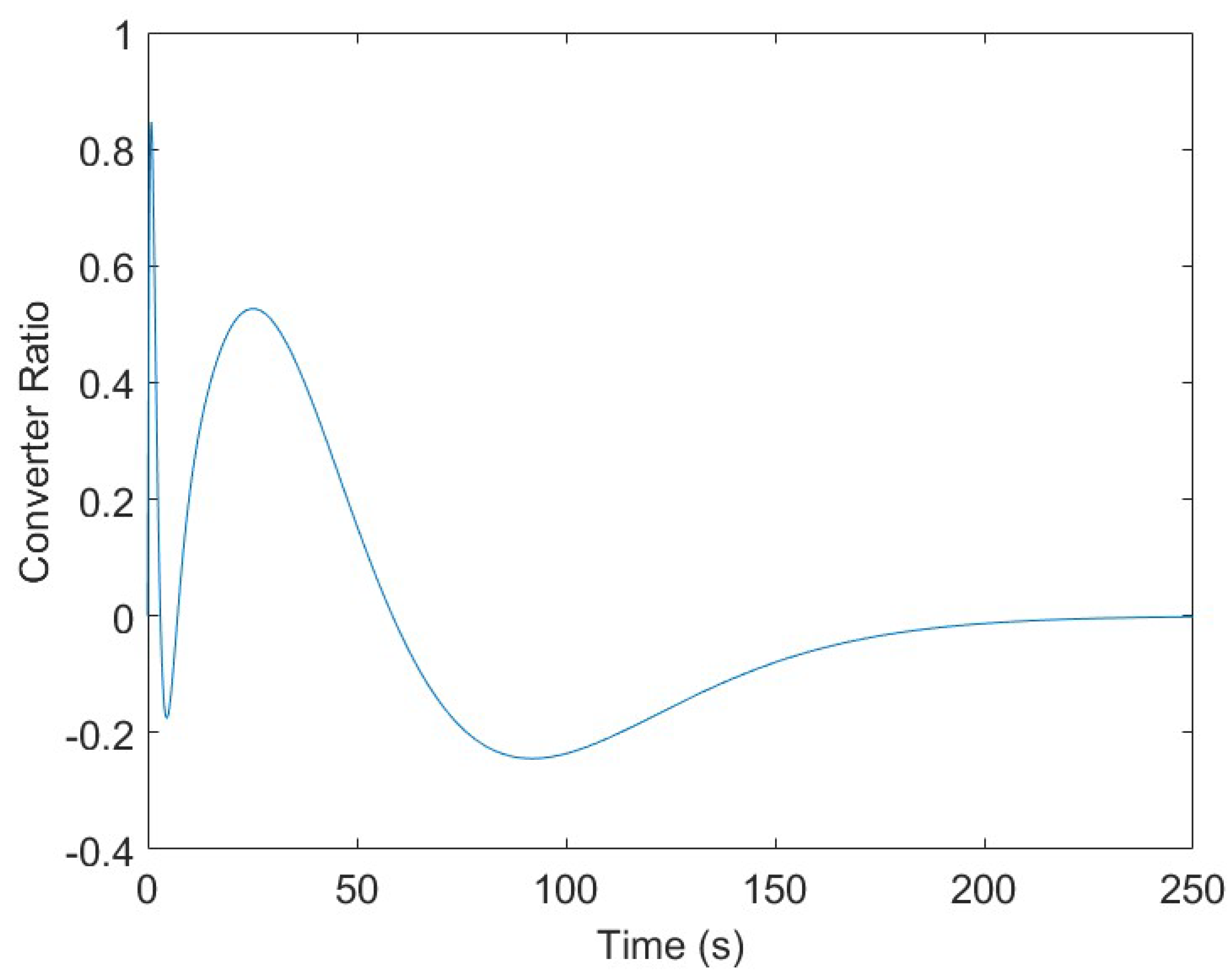
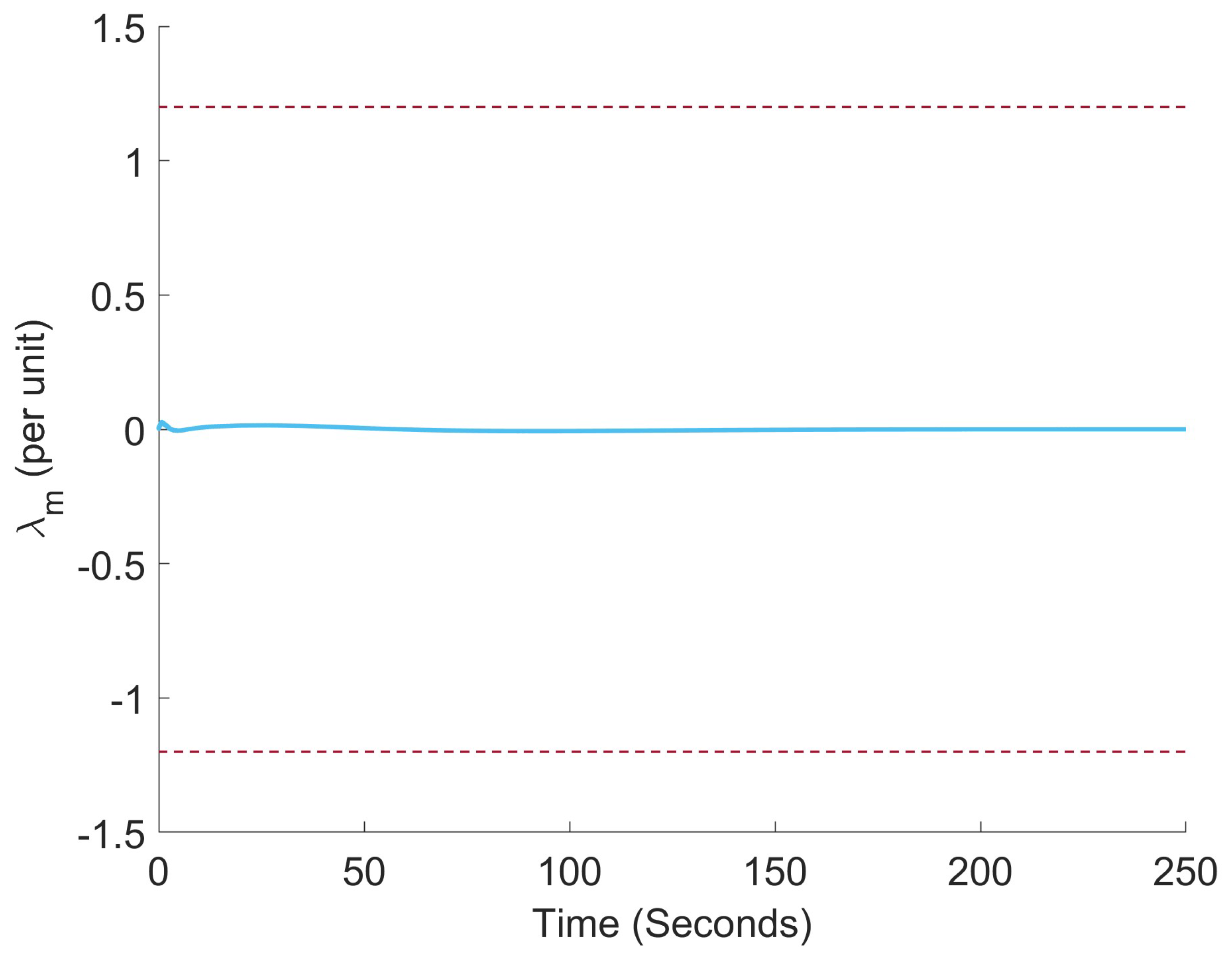
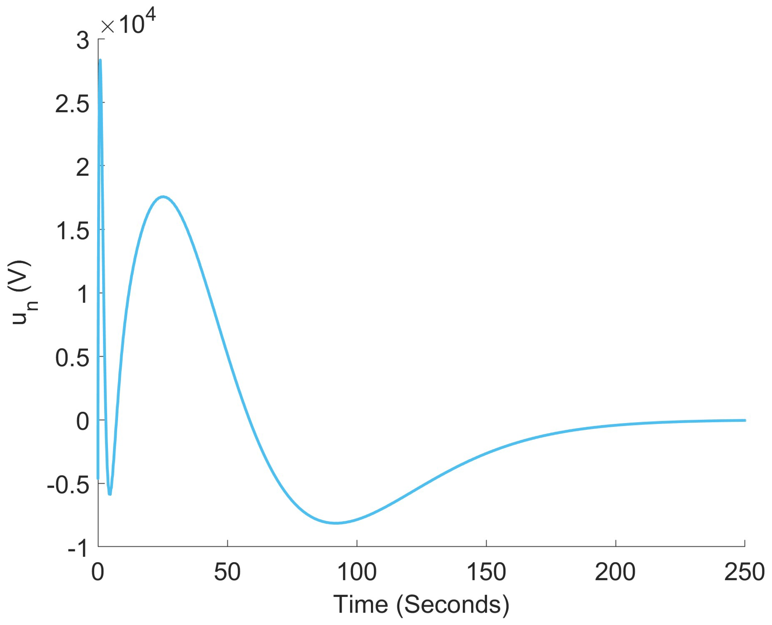
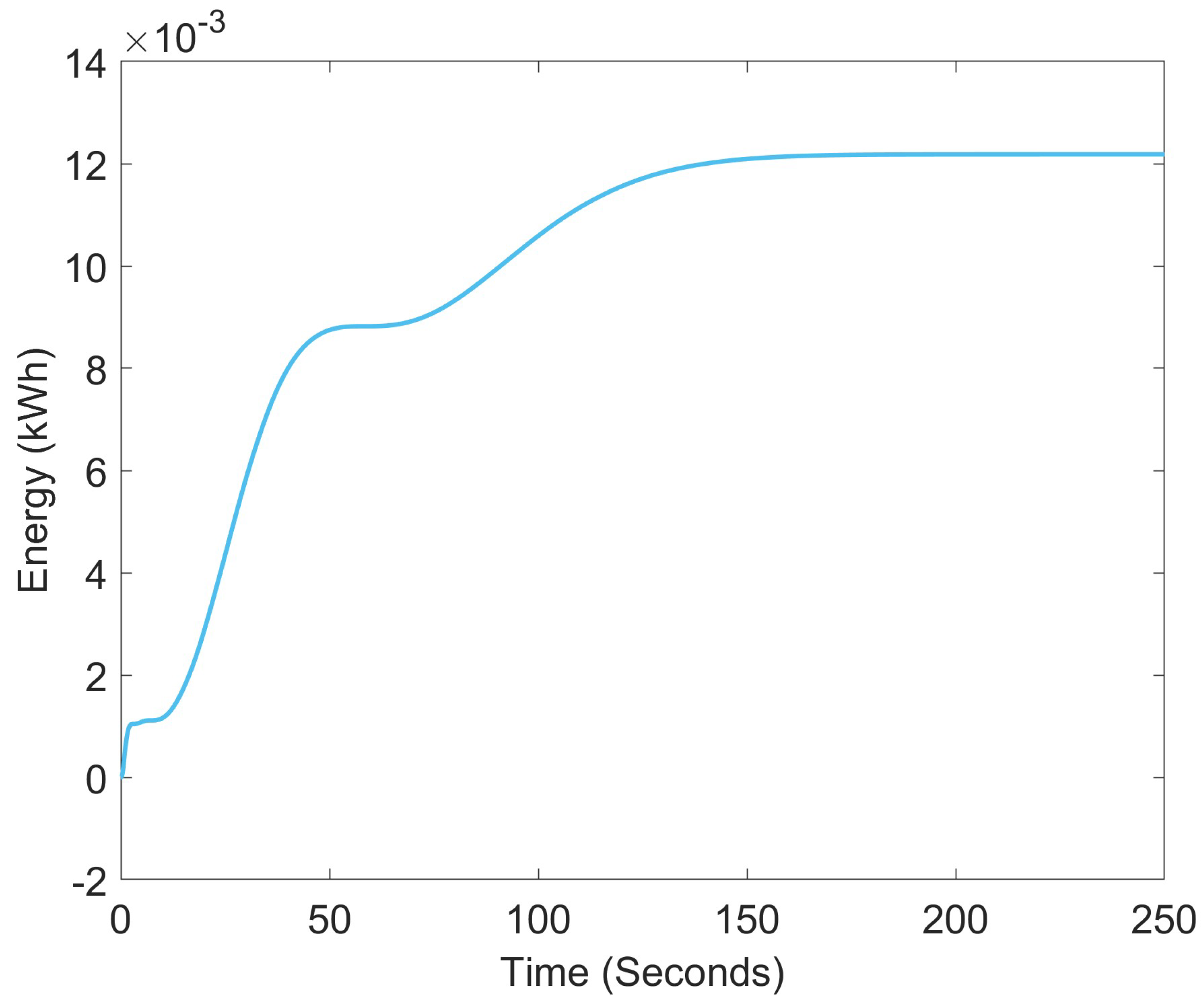
Figure 6, Figure 7, Figure 8, Figure 9, Figure 10 and Figure 11 illustrate the transformer’s magnetic core flux, control effort, error in tracking the commanded voltage, instantaneous power draw, energy storage state, and bandwidth. Additionally, this section details the performance of the flywheel energy system itself, with Figure 12, Figure 13 and Figure 14 depicting the flywheel’s Bode plot, angular velocity over time, and converter ratio to provide sufficient bus voltage.

5. Discussion

Given the specified parameters, the system successfully meets the performance criteria. Throughout the duration of the HEMP E 3 insult, the values of λ m remain consistently near zero, significantly exceeding the required criterion of 1.2 pu λ m 1.2 pu . The neutral blocking device necessary for mitigating the HEMP insult demands a control effort of up to approximately 28 kV . The required angular velocity and actual angular velocity are shown in Figure 13. It can be seen that the actual angular velocity of the spinning mass remains above the required angular velocity at all times during the insult. This suggests that the energy of the energy storage system meets the requirements. The Hamiltonian control law itself requires approximately 13 Wh of energy to operate. Any additional energy loss is due to bearing friction in the flywheel system and from the converter. From Figure 11, the cutoff frequency is at around 5 Hz . An ideal actuator would maintain unity gain to approximately 10 times the required bandwidth from the controller. The flywheel in this paper has approximately 20 times the required bandwidth. Thus, bandwidth requirements are also met. Lastly, the maximum required power output is less than 3 kW . This power output level is also within reason and can be met with today’s devices [32]. An example of a flywheel device that more than exceeds system requirements is the VYCON Flywheel Energy Storage System, Option Level 1. The output voltage would need to be stepped up, but the power output of such a device is 300 kW . This device is capable of storing 1.44 kWh of energy, meeting system specifications by two orders of magnitude. Additionally, these flywheels are rated to last over 20 years, a significant improvement over chemical-based energy storage (i.e., batteries and capacitors). The cost for this flywheel system ranges from USD 65–100 k, depending on the vendor. This is a fraction of the cost of ABB SolidGround, a capacitor neutral blocking device. Adjusted for inflation, the cost of the blocking capacitor is approximately USD 500 k.
A recurring claim throughout this paper has been that the Hamiltonian controller acts as an energy storage optimal controller. To provide evidence for this claim, an additional simulation of a feedforward energy optimal control law, derived following the procedure laid out in [27], was generated for the transformer model. The control law aims to minimize the cost function
J = 1 2 0 t f ( η λ m 2 + W 2 ) d τ ,
where λ m is the transformer core flux, W is the energy stored in the transformers, and η is a weighting constant to weigh both terms equally. Figure 15, Figure 16 and Figure 17 depict the λ m , control effort, and energy state of the transformer, following the energy-storage-optimal feedforward control law. Comparing these figures against Figure 6, Figure 7, and Figure 10 reveals that the Hamiltonian feedback control law in this paper is indeed an energy storage optimal controller.

6. Conclusions

HEMP insults pose significant challenges to the power grids that have yet to be comprehensively addressed. Numerous solutions exist for HEMP mitigation, and it is essential to explore and characterize these options before implementing them at the grid scale. This paper investigates the feasibility of one such mitigation strategy aimed at responding to E 3 HEMP insults. A neutral-blocking Hamiltonian controller was developed, which minimizes the energy storage requirements for mitigation. The optimality of the feedback control law was successfully verified by a feedforward energy optimal controller. The control effort necessary for the controller was generated using a flywheel energy storage system. The optimal control law formulated in this study facilitated the derivation of the specification requirements for the flywheel energy storage system. It was determined that, given the specified parameters for the flywheel energy storage system, effective mitigation of the HEMP insult is achievable. Many devices commercially available today exceed the requirements of the controller presented here. It should be noted that this is just one of many strategies for the mitigation of HEMP E 3 insults on the power grid.
Future research should focus on evaluating other energy storage devices suitable for use in neutral blocking applications. Alternative mitigation strategies, such as transmission line blocking devices and load-side exogenous power drain controllers, should be explored. There may exist devices that offer comparable performance to neutral blocking devices at a lower cost. Other future work on this topic will include hardware in the loop validation and a scaled, system level analysis for minimizing device placement costs. Additionally, further work on redundancy and reliability at a large scale needs to be carried out using the feasibility and specifications analysis provided in this study.

Author Contributions

The authors have all contributed different portions of the research presented here. Contributions are listed as follows: conceptualization, R.D.R.III, W.W.W. and D.G.W.; methodology, C.A.L. and R.D.R.III; software, C.A.L.; validation, C.A.L.; formal analysis, C.A.L.; investigation, C.A.L.; resources, D.G.W.; data curation, C.A.L.; writing—original draft preparation, C.A.L.; writing—review and editing, R.D.R.III, W.W.W. and D.G.W.; visualization, C.A.L.; supervision, D.G.W.; project administration, D.G.W.; and funding acquisition, D.G.W. All authors have read and agreed to the published version of the manuscript.

Funding

This paper was supported by the Laboratory Directed Research and Development program at Sandia National Laboratories, a multi-mission laboratory managed and operated by National Technology and Engineering Solutions of Sandia LLC., a wholly owned subsidiary of Honeywell International Inc. for the U.S. Department of Energy’s National Nuclear Security Administration under contract DE-NA0003525. The views expressed in the article do not necessarily represent the views of the U.S. Department of Energy or the United States Government.

Institutional Review Board Statement

Not applicable.

Informed Consent Statement

Not applicable.

Data Availability Statement

The data presented in this study are available upon request from the corresponding author due to federal guidelines and Sandia National Labs policy and procedure.

Acknowledgments

This article has been authored by an employee of National Technology Engineering Solutions of Sandia, LLC under Contract No. DE-NA0003525 with the U.S. Department of Energy (DOE). The employee owns all right, title, and interest in and to the article and is solely responsible for its contents. The publisher, by accepting the article for publication, acknowledges that the United States Government retains a nonexclusive, paid-up, irrevocable, world-wide license to publish or reproduce the published form of this article or allow others to do so for United States Government purposes. The DOE will provide public access to these results of federally sponsored research in accordance with the DOE Public Access Plan (https://www.energy.gov/doe-public-access-plan (accessed on 2 October 2025). The authors would like to thank Lee J. Rashkin and Steven F. Glover for their technical reviews.

Conflicts of Interest

The authors declare no conflicts of interest.

References

  1. Foster, J.S., Jr.; Gjelde, E.; Graham, W.R.; Hermann, R.J.; Kluepfel, H.M.; Lawson, R.L.; Soper, G.K.; Wood, L.L.; Woodard, J.B. Report of the Commission to Assess the Threat to the United States from Electromagnetic Pulse (emp) Attack: Critical National Infrastructures; Technical Report; Electromagnetic Pulse (EMP) Commission: McLean, VA, USA, 2008. [Google Scholar]
  2. Foster, R.A.; Frickey, S.J. Strategies, Protections and Mitigations for Electric Grid from Electromagnetic Pulse Effects; Technical Report; Idaho National Lab. (INL): Idaho Falls, ID, USA, 2016. [Google Scholar]
  3. Wang, D.; Li, Y.; Dehghanian, P.; Wang, S. Power grid resilience to electromagnetic pulse (EMP) disturbances: A literature review. In Proceedings of the 2019 North American Power Symposium (NAPS), Wichita, KS, USA, 13–15 October 2019; pp. 1–6. [Google Scholar]
  4. IEC 61000-2-9; Electromagnetic Compatibility (EMC)—Part 2: Environment—Section 9: Description of HEMP Environment—Radiated Disturbance. Basic EMC Publication; IEC (International Electrotechnical Commission): Geneva, Switzerland, 1996. Available online: https://webstore.iec.ch/en/publication/4141 (accessed on 17 August 2025).
  5. Sanabria, D.E.; Bowman, T.; Guttromson, R.; Halligan, M.; Le, K.; Lehr, J. Early-Time (E1) High-Altitude Electromagnetic Pulse Effects on Trip Coils; Technical Report SAND2020-12133; Sandia National Labs: Albuquerque, NM, USA, 2020. [Google Scholar]
  6. Savage, E.; Gilbert, J.; Radasky, W. The Early-Time (E1) High-Altitude Electromagnetic Pulse (HEMP) and Its Impact on the U.S. Power Grid; Technical Report Meta-R-320; Metatech: Goleta, CA, USA, 2010. [Google Scholar]
  7. Hansen, C.W.; Catanach, T.A.; Glover, A.M.; Huerta, J.G.; Stuart, Z.; Guttromson, R. Modeling Failure of Electrical Transformers due to Effects of a HEMP Event; Technical Report; Sandia National Laboratories: Albuquerque, NM, USA, 2020. [Google Scholar]
  8. Shetye, K.; Overbye, T. Modeling and Analysis of GMD Effects on Power Systems: An overview of the impact on large-scale power systems. IEEE Electrif. Mag. 2015, 3, 13–21. [Google Scholar] [CrossRef]
  9. Faxvog, F.R.; Jensen, W.; Fuchs, G.; Nordling, G.; Jackson, D.B.; Groh, B.; Ruehl, N.; Vitols, A.P.; Volkmann, T.L.; Rooney, M.R.; et al. Power grid protection against geomagnetic disturbances (GMD). In Proceedings of the 2013 IEEE Electrical Power & Energy Conference, Halifax, NS, Canada, 21–23 August 2013; pp. 1–13. [Google Scholar] [CrossRef]
  10. Brouillette, D. Physical Characteristics of HEMP Waveform Benchmarks for Use in Assessing Susceptibilities of the Power Grid, Electrical Infrastructures, and Other Critical Infrastructure to HEMP Insults; Department of Energy Memo; U.S. Department of Energy: Washington, DC, USA, 2021. [Google Scholar]
  11. Donnelly, T.J.; Wilson, D.G.; Robinett, R.D.; Weaver, W.W. Top-Down Control Design Strategy for Electric Power Grid EMP (E3) Protection. In Proceedings of the 2023 IEEE Texas Power and Energy Conference (TPEC), College Station, TX, USA, 13–14 February 2023; pp. 1–6. [Google Scholar] [CrossRef]
  12. Morari, M. Robust stability of systems with integral control. IEEE Trans. Autom. Control 1985, 30, 574–577. [Google Scholar] [CrossRef]
  13. Nise, N.S. Control Systems Engineering; John Wiley & Sons: Hoboken, NJ, USA, 2020. [Google Scholar]
  14. Amiryar, M.E.; Pullen, K.R. A review of flywheel energy storage system technologies and their applications. Appl. Sci. 2017, 7, 286. [Google Scholar] [CrossRef]
  15. Hadjipaschalis, I.; Poullikkas, A.; Efthimiou, V. Overview of current and future energy storage technologies for electric power applications. Renew. Sustain. Energy Rev. 2009, 13, 1513–1522. [Google Scholar] [CrossRef]
  16. Schoenung, S.M.; Hassenzahl, W.V. Long- vs. Short-Term Energy Storage Technologies Analysis: A Life-Cycle Cost Study: A Study for the DOE Energy Storage Systems Program; Technical Report; Sandia National Laboratories (SNL): Albuquerque, NM, USA; Livermore, CA, USA, 2003. [Google Scholar]
  17. Schoenung, S.M.; Eyer, J. Benefit/Cost Framework for Evaluating Modular Energy Storage; Sandia Report SAND2008-0978; Sandia National Laboratories (SNL): Albuquerque, NM, USA, 2008. [Google Scholar]
  18. Goris, F.; Severson, E.L. A review of flywheel energy storage systems for grid application. In Proceedings of the IECON 2018-44th Annual Conference of the IEEE Industrial Electronics Society, Washington, DC, USA, 21–23 October 2018; pp. 1633–1639. [Google Scholar]
  19. Robinett, R.D., III; Wilson, D.G. Nonlinear Power Flow Control Design: Utilizing Exergy, Entropy, Static and Dynamic Stability, and Lyapunov Analysis; Springer: London, UK, 2011. [Google Scholar]
  20. Crouch, P.E.; van der Schaft, A.J. (Eds.) The variational criterion. In Variational and Hamiltonian Control Systems; Springer: Berlin/Heidelberg, Germany, 1987; pp. 60–84. [Google Scholar] [CrossRef]
  21. Wilson, D.; Weaver, W.; Robinett, R., III; Young, J.; Glover, S.; Cook, M.; Markle, S.; McCoy, T. Nonlinear Power Flow Control Design Methodology for Navy Electric Ship Microgrid Energy Storage Requirements. In Proceedings of the 14th International Naval Engineering Conference, Glasgow, UK, 2–4 October 2018; Volume 2018. [Google Scholar]
  22. Choudhury, S. Flywheel energy storage systems: A critical review on technologies, applications, and future prospects. Int. Trans. Electr. Energy Syst. 2021, 31, e13024. [Google Scholar] [CrossRef]
  23. Bolund, B.; Bernhoff, H.; Leijon, M. Flywheel energy and power storage systems. Renew. Sustain. Energy Rev. 2007, 11, 235–258. [Google Scholar] [CrossRef]
  24. Nguyen, X.P.; Hoang, A.T. The flywheel energy storage system: An effective solution to accumulate renewable energy. In Proceedings of the 2020 6th International Conference on Advanced Computing and Communication Systems (ICACCS), Coimbatore, India, 6–7 March 2020; pp. 1322–1328. [Google Scholar]
  25. Overbye, T.J.; Faxvog, F.R.; Jensen, W.; Fuchs, G.; Nordling, G.; Jackson, D.B.; Groh, B.; Ruehl, N.; Vitols, A.P.; Volkmann, T.L.; et al. Power Grid Geomagnetic Disturbance (GMD) Modeling with Transformer Neutral Blocking and Live Grid Testing Results. In Proceedings of the 2013 Minnesota Power Conference, Minneapolis, MN, USA, October 2013. [Google Scholar]
  26. Gurevich, V. Protection of Power Transformer from High Altitude Electromagnetic Pulse. Int. J. Res. Stud. Electr. Electron. Eng. 2020, 6, 17–24. [Google Scholar] [CrossRef]
  27. Lehman, C.A.; Robinett, R.D., III; Weaver, W.W.; Wilson, D.G. Solid State Transformer Controls for Mitigation of E3a High-Altitude Electromagnetic Pulse Insults. Energies 2025, 18, 1055. [Google Scholar] [CrossRef]
  28. Lehman, C.A.; Weaver, W.W.; Wilson, D.G.; Robinett, R.D. Active Controls of a Multi-Frequency Multi-Bus Microgrid Network Using Hamiltonian-Based Techniques. In Proceedings of the 2024 IEEE Energy Conversion Congress and Exposition (ECCE), Phoenix, AZ, USA, 20–24 October 2024; pp. 1144–1150. [Google Scholar]
  29. Lehman, C.A.; Robinett, R.D., III; Wilson, D.G.; Weaver, W.W. Comparison of Optimal Control Mitigation Techniques for E3 HEMP Insults Utilizing the Transformer Neutral Path. In Proceedings of the IEEE ECCE 2025, Philadelphia, PA, USA, 19–23 October 2025. [Google Scholar]
  30. Segaran, D. Dynamic Modelling and Control of Dual Active Bridge Bi-Directional Dc-Dc Converters for Smart Grid Applications. Ph.D. Thesis, RMIT University, Melbourne, VIC, Australia, 2024. [Google Scholar]
  31. Xue, L.; Mu, M.; Boroyevich, D.; Mattavelli, P. The optimal design of GaN-based dual active bridge for bi-directional plug-in hybrid electric vehicle (PHEV) charger. In Proceedings of the 2015 IEEE Applied Power Electronics Conference and Exposition (APEC), Charlotte, NC, USA, 15–19 March 2015; pp. 602–608. [Google Scholar]
  32. Chen, Y.; Zang, B.; Wang, H.; Liu, H.; Li, H. Research on Composite Rotor of 200 kW Flywheel Energy Storage System High Speed Permanent Magnet Synchronous Motor for UPS. In Proceedings of the 2021 24th International Conference on Electrical Machines and Systems (ICEMS), Gyeongju, Republic of Korea, 31 October–3 November 2021; pp. 398–403. [Google Scholar] [CrossRef]
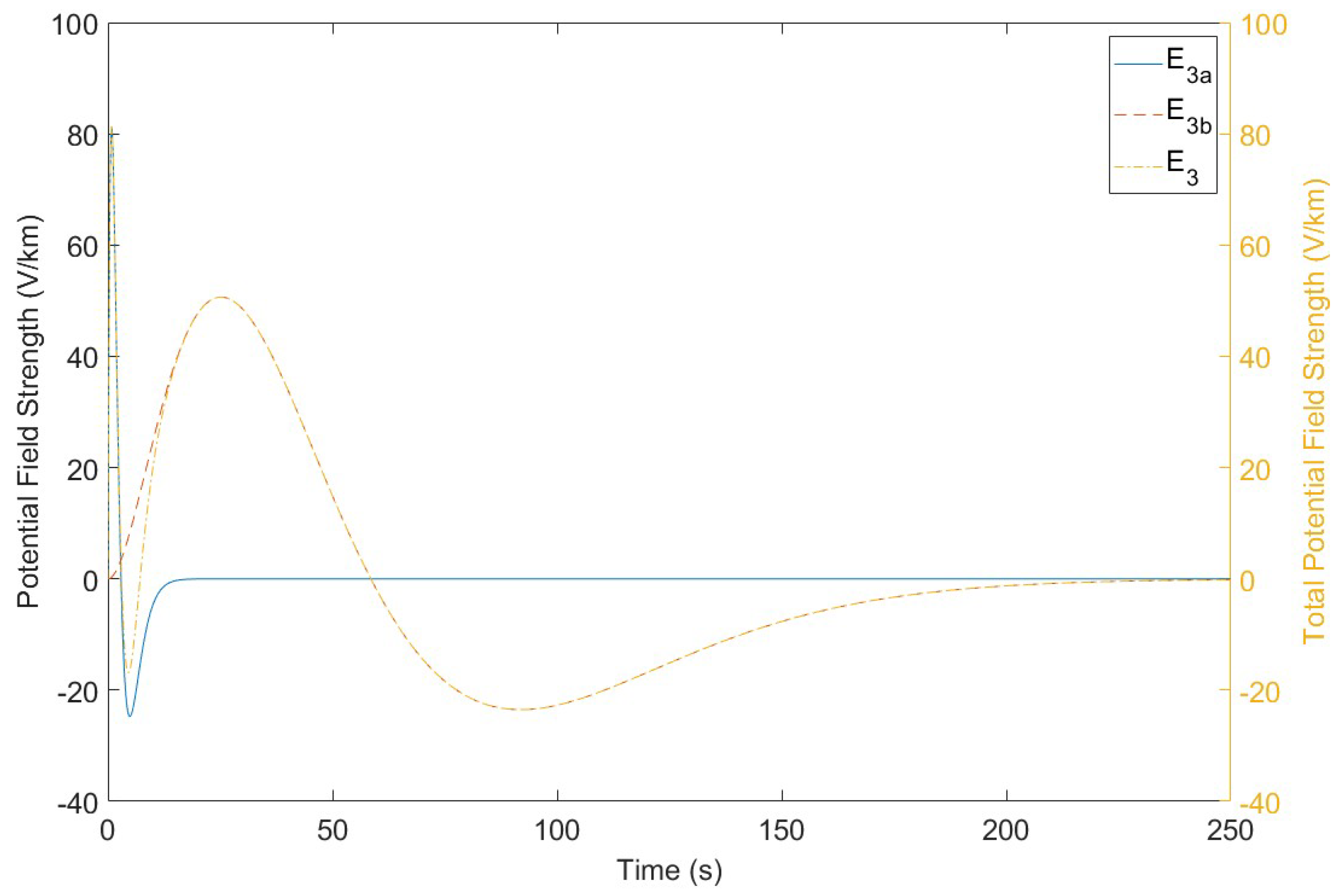
Figure 1. Depiction of the E 3 field waveform magnitude. The equations for the waveforms are given in (1) and (2) [10].
Energies 18 05294 g001
Figure 2. Schematic of the per-phase transformer with a neutral blocking device.
Energies 18 05294 g002
Figure 3. Plot of the curve defined by (6).
Energies 18 05294 g003
Figure 4. Diagram of the flywheel system used in the simulation [21]. The bus voltage v B is fed into the requested control effort u n on the per-phase transformer model in Figure 2. The green box surrounds the converter portion of the systems. The purple box surrounds the permanent magnet machine of the system. The gray box surrounds the flywheel component of the system.
Energies 18 05294 g004
Figure 5. Block diagram of the flywheel feedback mitigation system. The controller tracks a reference state vector of x r = 0 0 0 T . The white box surrounds the plant of the entire system and the orange box represents the recorded measurements of the actuator. The green box is the ideal optimal feedback control law being used as a feedforward command. The red box is the feedback controller used to implement the Hamiltonian control on a non-ideal actuator.
Energies 18 05294 g005
Figure 6. Transformer magnetic core flux in per unit (pu). The red dashed lines indicate the saturation limits of the transformer core ( ± 1.2 pu ). Both the mitigated and unmitigated system responses are shown in this plot for a better comparison.
Energies 18 05294 g006
Figure 7. Required control effort to implement the Hamiltonian control law, compared to the HEMP insult voltage on the connected transmission line.
Energies 18 05294 g007
Figure 8. Error tracking of the flywheel with commanded voltage.
Energies 18 05294 g008
Figure 9. Instantaneous power draw of the controller.
Energies 18 05294 g009
Figure 10. Energy requirements of the Hamiltonian control law.
Energies 18 05294 g010
Figure 11. Power spectral density of the control law implemented to mitigate the HEMP insult, with a roll-off frequency of around 5 Hz.
Energies 18 05294 g011
Figure 12. Bode plot of the linearized flywheel model illustrating the magnitude of v b / ζ . An arrow has been placed to show the frequency at which the control law’s PSD plot falls below 0 dB/Hz. This shows that the frequency response of the flywheel system is more than sufficient for the E 3 insult.
Energies 18 05294 g012
Figure 13. Angular velocity of the flywheel over time compared to the required flywheel angular velocity to maintain the commanded u n ( t ) .
Energies 18 05294 g013
Figure 14. Converter ratio, ζ , of the flywheel system over time.
Energies 18 05294 g014
Figure 15. λ m values over time with the control law minimizing the cost function in (24).
Energies 18 05294 g015
Figure 16. Control effort over time with control law minimizing cost function in (24).
Energies 18 05294 g016
Figure 17. Energy stored in the transformer over time with the control law minimizing the cost function in (24).
Energies 18 05294 g017
Table 1. Parameters with simulation values and associated descriptions.
ParameterDescriptionValue
J f Moment of Inertia of Flywheel25 kg m2
k t Torque Constant20 Nm/A
R p m Armature Resistance0.1 Ω
L p m Armature Inductance0.1 mH
C u Converter Capacitance1 mF
R c u Converter Resistance10 M Ω
L u Line Inductance10 mH
R u Line Resistance0.1 Ω
BShaft Windage 10 6 Nm / rad s
Table 2. Table of flywheel system requirements.
Power DrawEnergy Draw/StorageBandwidth
Control Law Requirement2.93 kW12.3 Wh4.9 Hz
System Flywheel100 kW9.75 kWh80 Hz
Disclaimer/Publisher’s Note: The statements, opinions and data contained in all publications are solely those of the individual author(s) and contributor(s) and not of MDPI and/or the editor(s). MDPI and/or the editor(s) disclaim responsibility for any injury to people or property resulting from any ideas, methods, instructions or products referred to in the content.