1. Introduction
Thermal energy storage systems significantly improve the efficiency, flexibility and life-time of technical systems in which heat supply and demand are shifted over time. This technology is gaining relevance with the increasing electrification of transport and enables new thermal management concepts for air conditioning as well as for temperature stabilization of batteries [
1,
2]. Particularly in battery electric vehicles (BEVs), thermal energy storage systems open up new approaches for saving battery capacities given heating and cooling requirements in extreme cold and warm seasons, avoiding range losses of up to 50% and 30% [
3,
4,
5]. Central prerequisites for this are strongly linked with high storage densities, high thermal output at a constant temperature level and scalability in order to fulfil requirements in terms of compactness and controllability for different BEVs.
During cold seasons different thermal energy storage options based on sensible and phase-change materials (PCMs) as well as on sorption and thermochemical systems were analyzed and compared in [
6]. High utilization potentials are given by sorption [
7] and thermochemical systems [
8,
9] due to their low-loss and long-term storage, but they still require further development in terms of complexity, performance, integration and systemic storage density. PCM-based concepts with organic materials [
10,
11] at moderate temperature levels are particularly suitable for coupling with liquid thermal management systems, but they are limited in performance due to their low thermal conductivity. At higher temperature levels, metallic PCMs [
12] and sensible solid-media storage systems [
13] in particular show great potential for achieving the target values in terms of compactness, performance and scalability. Here, the basic idea is to generate thermal energy electrically before the drive (charging), to conserve it efficiently and to make it available again during the drive (discharging) via a controllable bypass system. Initial experimental results for a ceramic honeycomb-based solid-medium storage system [
14] confirmed high discharge capacities of over 5 kW with systemic storage densities of up to 150 Wh/kg. Such inventory options are also characterized by their high robustness, life-time and cost efficiency and are used as regenerators in industrial applications with higher requirements in terms of temperature and cyclic loads.
For cooling requirements in BEVs during warm seasons, the aforementioned sorption [
7] and thermochemical systems [
8,
9] are suitable options in addition to PCM-based materials whose melting points are above the lower operating temperature of up to −30 °C for today’s compression refrigeration machines. In this field, studies are focusing on the integration of thermal energy storage within the coolant circuit [
15,
16,
17], which allows greater flexibility and increased efficiency during the drive through storage-based air conditioning. In addition to water, alternative PCMs which have melting temperatures of up to −50 °C depending on their application are also being investigated for mobile applications [
18,
19]. Due to the significantly lower temperature difference in thermal energy storage systems for cooling applications, the selection of a suitable heat-transferring structure is crucial for effectively transporting cold from or to the storage medium. In addition to tube- [
20] and plate-based structures [
21], it was shown in [
22] that such challenges can be solved with scalable TPMS (Triply Periodic Minimal Surface)-based geometries, allowing high utilization and high effective storage densities of up to 100 Wh/kg for water-based designs.
Overall, the studies for storage-based air conditioning options in BEVs so far have focused largely on concepts for heat supply in winter or, to a lesser extent, cooling supply in summer. However, the successful implementation of thermal energy storage systems in BEVs requires systemic solutions for all seasons in different air conditioning conditions. In this regard, the first solutions were presented in [
23,
24] with two PCM-based storage systems integrated within a heat pump system achieving battery electric energy savings of 65.9% and 26.2% in summer and winter operations, respectively. Despite these initial investigations, there is still a lack of holistic analyses, particularly with regard to storage density and performance in relation to seasonal air conditioning requirements. In addition, alternative operational uses for thermal energy storage systems are required at times when there is no need for air conditioning in order to improve the total utilization.
For this purpose, a promising approach is presented based on an independent, electrically heated, Brayton process-based cycle. Such systems are currently being investigated in large-scale applications and allow a flexible coupling and decoupling of electrical and thermal energy in a left-hand or right-hand process during charging and discharging [
25,
26]. Transferring this concept to BEV-typical requirements at a kW scale based on compact turbomachinery (e.g., power modules in micro gas turbines [
27]) or turbocharger systems, new thermal management options are being opened. In addition to heat and cold supply, electrical energy output from a thermal storage system at times when there are no air conditioning requirements is possible, and unused recuperated braking energy can be integrated with high load dynamics. The independent Brayton process-based cycle also avoids systemic integration hurdles in existing air conditioning systems, which opens up new paths for retrofitting, especially for larger BEV systems (busses, trucks, trains, and ships).
Overall, the primary aim of this publication is to identify for the first time a holistic, balanced thermal energy storage system with high storage density and performance for winter and summer conditions and to capture its potential for optional electrical energy output at times when there is no need for air conditioning. Detached from the underlying Brayton process, the knowledge on storage solutions can also be transferred directly to today’s air conditioning systems due to comparable interface temperatures, although integration hurdles, particularly with regard to dynamics and control, still need to be addressed.
3. Modeling
Central thermal components in the year-round storage system for BEV air conditioning are the TPMS-based HTES with internal heating and the TPMS-based water/ice LTES. Detailed model descriptions, including validations, can be found in the literature [
13,
14,
22] and are summarized in a compact way below. The HTX was calculated as a stationary component in counterflow based on NTU methods [
30] due to its comparatively low storage capacity. As with the storage components, a TPMS-based geometry was also used here [
28,
29]. The compressor, the adiabatic expansion valve and the optional turboexpander were idealized and described by isentropic states of changes, where isentropic efficiency was taken into account for the compressor and the turbine.
3.1. HTES
The electrically heated TPMS-HTES is based on heating wires integrated within the (electrically non-conductive) ceramic structure, which heat the solid material via radiation and conduction. The heating wires themselves can be formulated stationarily due to their extremely low storage capacity, whereas the ceramic storage inventory can be modeled transiently.
The heat balance equations for a cylindrical storage design are based on a heterogeneous porosity approach, where a distinction is made between the ceramic inventory (index S) and the gaseous HTF (index F)—due to the spatial separation for two media (index i). For a one-dimensional formulation, the axial (z) temperature profiles (T) over time (t) are obtained according to Equations (1) and (2):
Here, the geometric parameters ε
i describe the HTF-dependent void fractions and a
V,i describe the specific surface within the storage structure as well as the thermally insulated casing (index Ins). The heat transport in the TPMS-based structure or to the environment (index U) is captured by the parameter k, where the thermal resistance inside the TPMS structure is taken into account [
31] in addition to the heat transfer coefficient as a function of the flow velocities (w
F) [
32].
The heating wires themselves are implemented here in the channel-shaped structures of the cycle-integrated HTF zone and transfer the electrically generated heat from the heating wires (index P) to the ceramic storage inventory via an effective radiation coefficient (kP). Temperature-averaged material values are used for the density (ρ), the specific heat capacity (c) and the thermal conductivities (λ). In addition, a control algorithm is implemented within the model to limit the heating wire load by adjusting the heating power to a maximum permitted heating wire temperature (TP,max).
3.2. LTES
The model developed for latent thermal energy storage is based on an axial formulation for the storage and fluid phase. Analogous to the HTES, a heterogeneous porosity approach was used, where the storage medium was expressed in an enthalpy-based fashion due to the phase change. In a dimensionless formulation in the axial direction (η
z) and in time (ξ) by normalization over the storage length and charging/discharging duration, as well as by a relation to the melting enthalpy and temperature, the balance Equations (3) and (4), taking into account heat losses, are expressed by the following:
The variables
and
represent the de-dimensionalized enthalpy and temperature, while the parameters Π, Λ and Ψ represent the dimensionless duration, storage length and heat losses. These include material data, mass flow, the latent storage mass, void fractions, the specific surfaces of the internal structure and the thermally insulated casing, the charging/discharging duration, and the internal effective heat transfer coefficient. The latter considers, in addition to the heat transfer coefficient according to [
32], the thermal resistance within the phase-change medium via a dimensionless, parameterized formulation.
4. Results
Initially, investigations were conducted in order to identify systemically efficient design solutions with high storage densities for winter and summer operations. These findings were then used to derive a holistically matched storage system allowing year-round air conditioning for BEVs. Based on this system solution, central transient characteristics are presented for the respective seasons in addition to initial results on electrical energy output during times with no air conditioning demand in the BEV.
4.1. Specifications and Assumptions
In principle, the storage system analyzed here includes a large number of degrees of freedom in terms of component specifications and boundary conditions. Due to the systemic nature of the investigations and in order to limit the solution space, representative air conditioning requirements and geometry specifications were defined. These assumptions represent typical specifications for mid-range vehicles, electrical power supply and geometries. The results can also be transferred to larger BEV vehicles, to adapted air conditioning requirements or to further optimizations due to the good scalability of the system in terms of performance and capacity.
Key specifications for the seasonal system investigations are summarized in
Table 1 and
Table 2. The storage mass of the HTES inventory was kept constant at a mass of 10 kg in order to enable a comparison with the present reference concept [
14] only designed for winter operation. An installed power of 3.5 kW was assumed for the electrical heating wires within the HTES during winter operation.
The values for mass flow rate, pressure ratio and isentropic efficiency used in summer operation during charging are based on typical specifications for compact turbomachinery [
27]. Specifications based on higher performance classes lead to conceptually comparable results, where shorter charging times and higher heating and cooling capacities are achieved.
The TES and HTX have a cylindrical shape with a length-to-diameter ratio of 1 and are based on TPMS geometries (Fischer–Koch S). Within the TES, the volume fractions of the spatially separated media were evenly divided through the inner wall with a certain thickness (s
W). However, in the HTX, the void fractions and the specific surface (a
V) were determined iteratively within the simulation studies in order to identify solutions with the highest gravimetric power density. Efficient, microporous thermal insulation was used, and sufficiently dimensioned wall thicknesses (s
Ins) were specified to maintain a permitted surface temperature. The central specifications used are summarized in
Table 3.
In a critical scenario, the respective ambient conditions were used as initial temperatures for both thermal energy stores. The non-specified mass flow rates were determined iteratively in the transient system simulations in order to ensure constant thermal outputs for BEV air conditioning as defined in
Table 1 and
Table 2. The results shown below include only those solutions whose total relative pressure losses fall below 2% of the respective maximum system pressure.
The studies here focus on investigations into gravimetric storage density as a function of the resulting charging and discharging durations. Volumetric optimizations, also with regard to geometric specifications fixed here (
Table 3), will be the focus of future activities.
4.2. Systemic Results for Heating and Cooling
The results are based on variation studies regarding central input values for system behavior: the constant HTX inlet and outlet temperature inside the TES cycle and the storage mass of the LTES. The storage mass of the HTES itself was kept constant at 10 kg in order to enable a comparison with the present reference concept [
14] only designed for winter operation.
4.2.1. Storage System for Heating
The results in
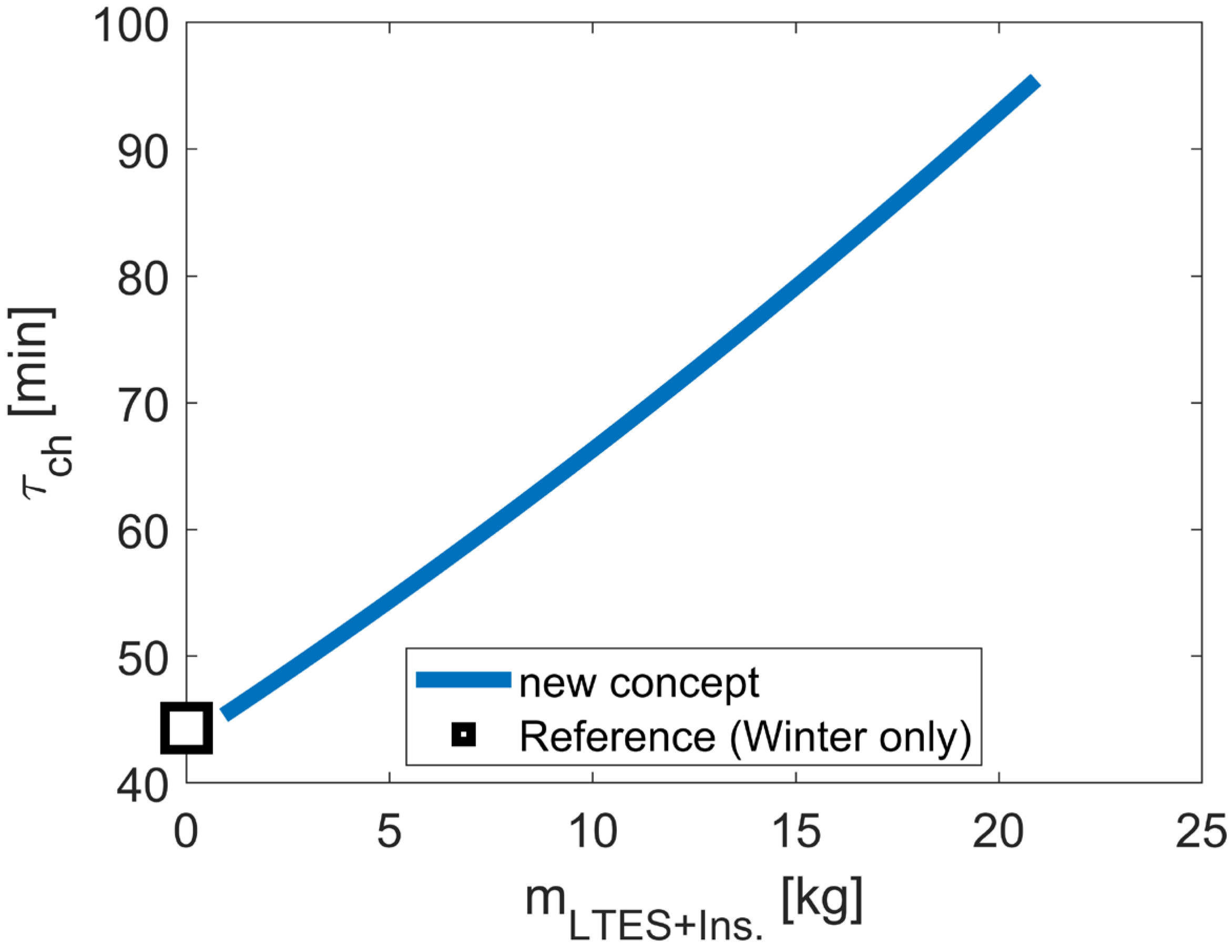
Figure 5 show increasing charging durations with growing LTES storage masses, where the lowest charging period is achieved with the reference concept—the electrically heated HTES only designed for winter operation [
14]. The reason for this is the increasing storage capacities due to the systemically integrated LTES component in the extended concept and the constant electrical heating powers inside the HTES.
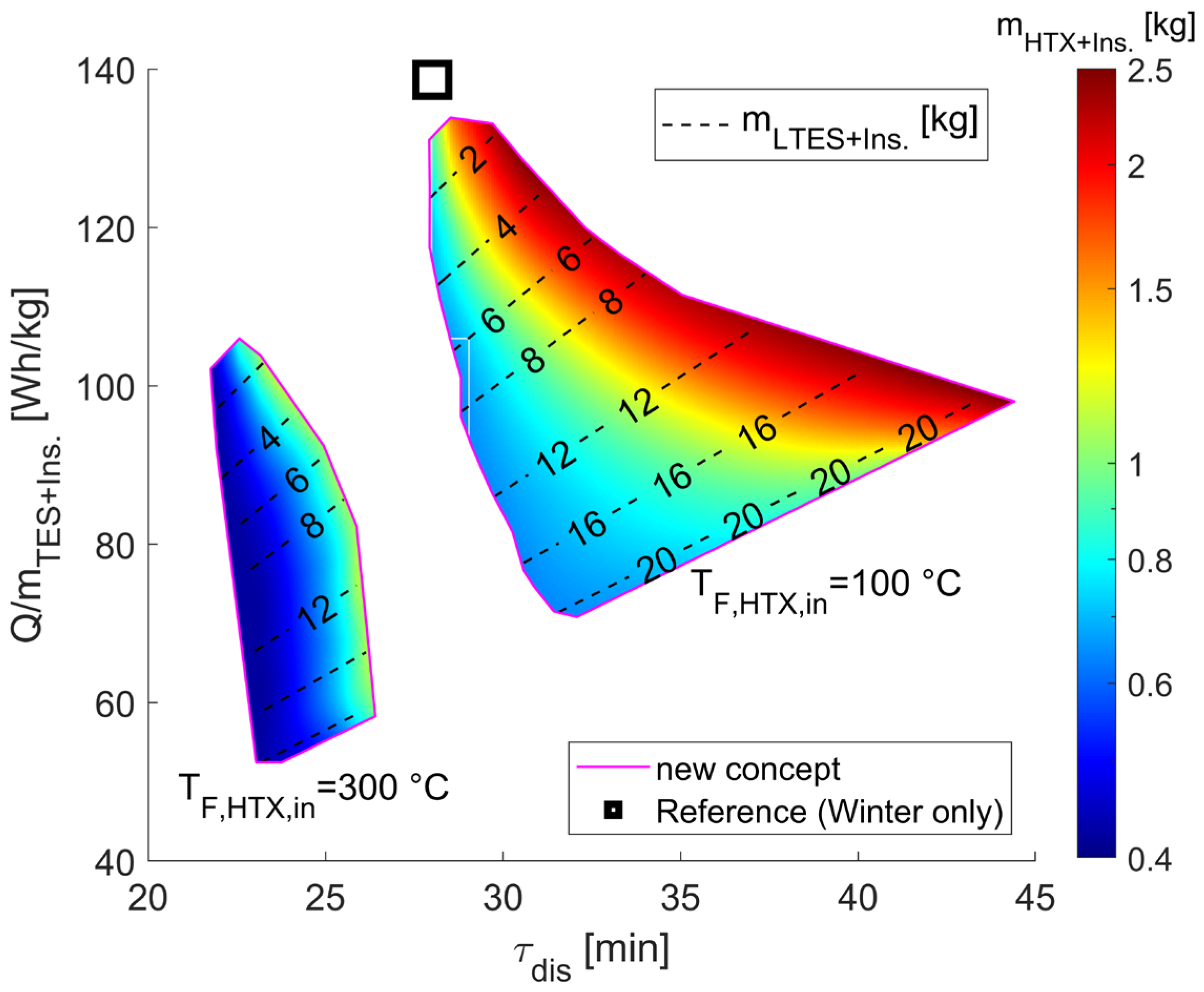
Results on the storage densities and discharge durations as a function of the LTES storage mass, (cycle-internal) HTX inlet temperature and its dimensions, including respective thermal insulations, are shown in
Figure 6.
As visible in the colored solution fields, increasing LTES storage masses leads to decreasing effective storage densities but simultaneously to longer discharge times. This is based on the lower storage densities of the LTES heated to maximal temperatures of 80 °C compared to the 800 °C heated HTES and effectively increasing storage capacities in the system overall. Furthermore, systemic improvement can be achieved with higher heat exchanger sizes and thus more effective heat transport. This effect is linked to increasingly advantageous TES temperature conditions inside the cycle, achieving higher storage utilization of the respective temperature potentials in the LTES and HTES.
Focusing on the two colored solution fields for different HTX inlet temperatures inside the cycle, this contrary relationship between HTX and LTES size is obvious. Here, with the higher HTX inlet temperature of 300 °C, lower HTX masses are needed, but, simultaneously, lower effective storage densities and discharging times are reached due to higher TES requirements. In contrast, lower HTX inlet temperatures significantly improve the solution field in terms of systemic efficiency but require moderately higher HTX masses.
Compared to the present reference concept, an additional LTES component and an indirect heat transfer to the BEV cabin via the HTX results in lower systemic storage densities. However, the results also point out that with suitable configurations in terms of cycle-internal HTX inlet temperatures and HTX dimensions, moderate losses in the systemic storage densities can be compensated by comparable increases in the discharge durations.
4.2.2. Storage System for Cooling
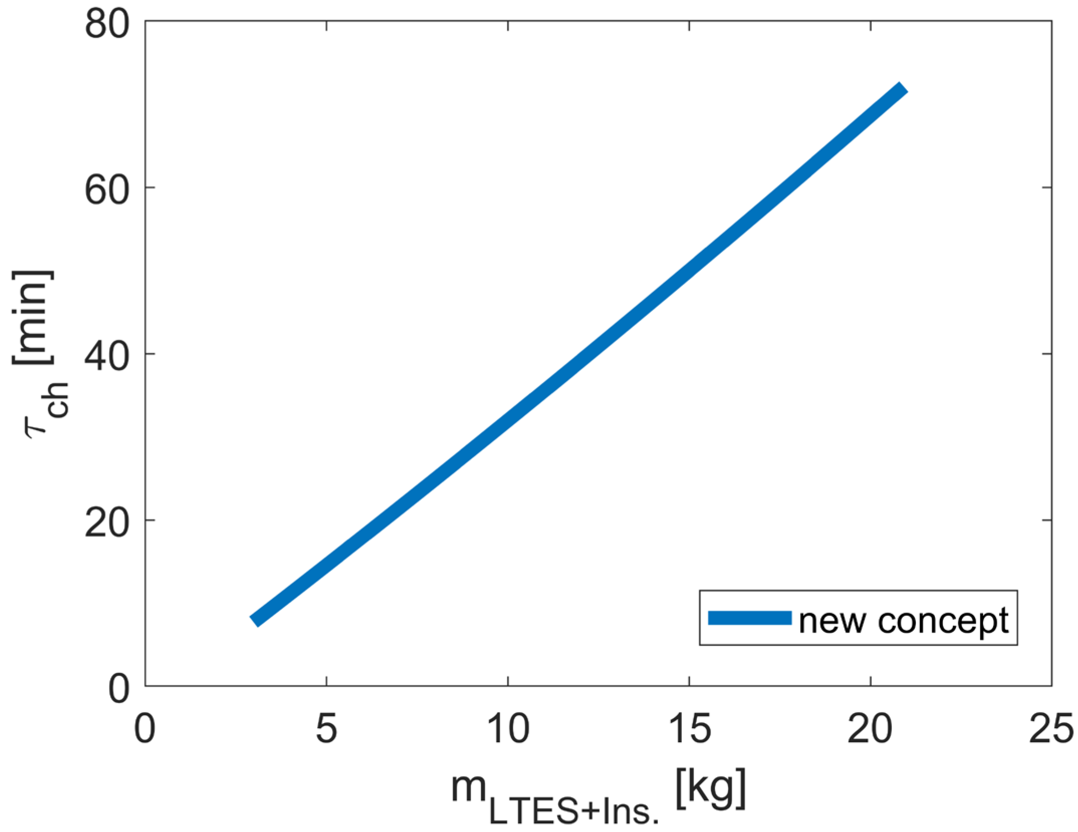
In comparison to winter operation, analogous correlations between charging durations and LTES storage masses can be seen in
Figure 7. With increasing storage capacities, the charging times increase linearly, leading to freezing of the water in the LTES.
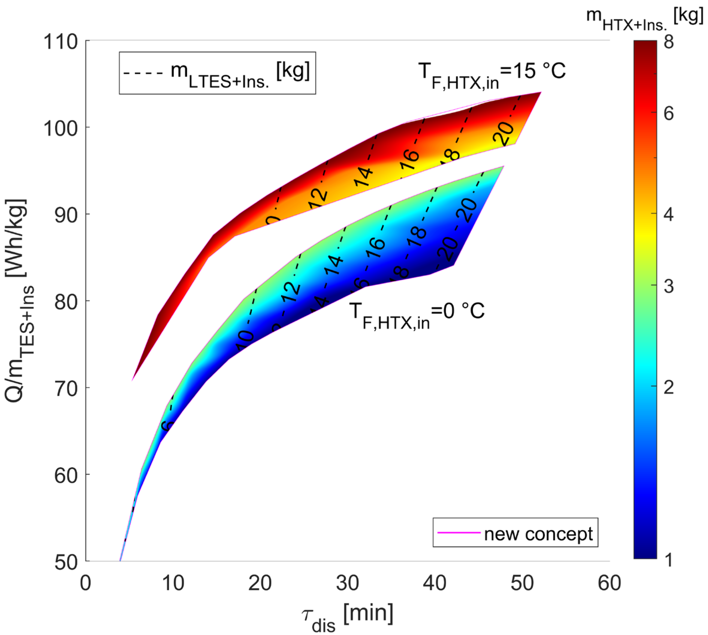
Results on storage density and discharge duration as a function of LTES storage mass, (cyclic-internal) HTX inlet temperature and its dimensions, including thermal insulations, are shown in
Figure 8.
As visible in the colored solution fields, increasing LTES storage masses leads to higher effective storage densities and simultaneously to longer discharge durations. The reason for this is the increase in the residence time of the HTF passing the LTES, thus reaching higher storage utilization. Analogous to the results in winter operation, an improvement in effective storage density and discharge duration can be achieved with increasing HTX dimensions and higher HTX effectiveness, respectively.
This effect can also be seen here in the colored solution fields for the HTX inlet temperature. Higher HTX inlet temperatures—and thus higher requirements for HTX—result in the largest HTX masses but allow, simultaneously, increasing effective storage densities and discharge times. The reason for this is associated with the lower cooling requirements for the LTES, resulting in lower LTES mass flow rates in bypass operation and thus a more effective utilization of the low-temperature potential in the LTES.
4.2.3. Storage System for Heating and Cooling
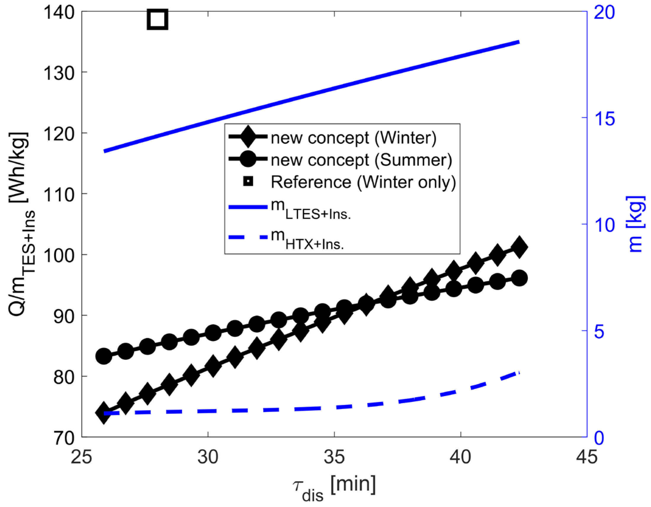
So far, the results for the extended storage system in winter and summer operations show increasing effective storage densities with adequate temperature ratios inside the Brayton cycle and component dimensions. For this, separate studies for winter and summer were conducted in the previous investigations. However, for the selection of a holistic concept for air conditioning throughout the year, solutions with identical component specifications are needed. For this, all-seasonal configurations with maximal storage densities (including thermal insulation) were identified, whereby additional assumptions were defined regarding identical discharging times for winter and summer operations. Key results are shown in
Figure 9.
Across the seasons, the results show comparable storage densities, where higher improvements in winter operation are visible with increasing discharge durations or LTES masses. This is based on higher utilization rates of the parallel operating TES in winter with the additional existing thermal potential of heated water in the LTES. Furthermore, higher effectiveness is associated with increasing HTX masses, resulting basically in the selection of identical component configurations and suitable temperature ratios inside the Brayton cycle. In comparison with the present reference concept only designed for winter operation, the extended concept compensates with a LTES mass of 17 kg lower effective storage densities with comparably longer discharge durations. For a selected configuration solution with an LTES storage mass of 18 kg, central results on component and system levels are summarized in
Table 4 and
Table 5.
As can be seen from
Table 4 and for the scenario considered here, in addition to the 10 kg HTES inventory mass, only 12.7 kg of water is needed in the LTES in order to maintain a constant heat supply of 5 kW (winter) or a constant cold supply of 2.5 kW (summer) over a period of 41 min via the HTX. The geometric configurations of the TPMS-based structures used here (Fischer–Koch S) show an average cell size of 30 mm, and the void fractions between 30 and 50% for each channel path are within a typical range of manufacturability for today’s 3D printers suitable for a wide range of materials. Additionally, the results point to the relatively large thermal insulation effort compared to the storage masses, which significantly reduces the effective storage densities in
Table 5. However, with increasing TES capabilities, as required in busses or trucks, these unfavorable conditions decrease significantly, resulting in higher effective storage densities. For the HTX itself, only low temperature requirements with a maximum of 100 °C are needed, offering alternative materials with low densities as a base for the TPMS structures in addition to aluminum.
The studies focused on design relating to the gravimetric storage density. The resulting volumetric results are also summarized in
Table 4. In addition to the still unused geometric degrees of freedom, holistic optimizations with regard to volumetric storage densities are needed in future works to allow significant reductions in terms of space demand.
4.3. Transient Results for Heating, Cooling and Power Supply
For the selected configuration solution, central transient temperature and mass flow characteristics as well as LTES-phase conditions (water/ice) are presented below for winter and summer operations during charging and discharging. In addition, initial findings on the electrical energy output by the storage system during discharging at times when no air conditioning is required in the BEV are presented.
4.3.1. Storage System for Heating
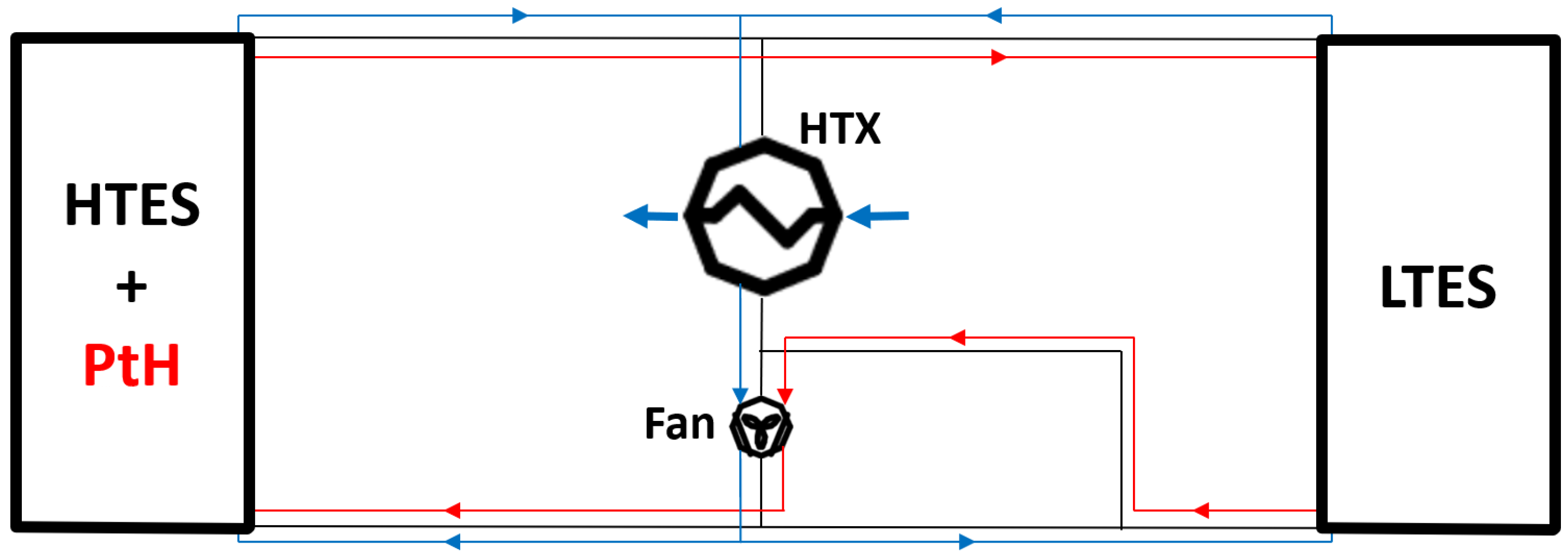
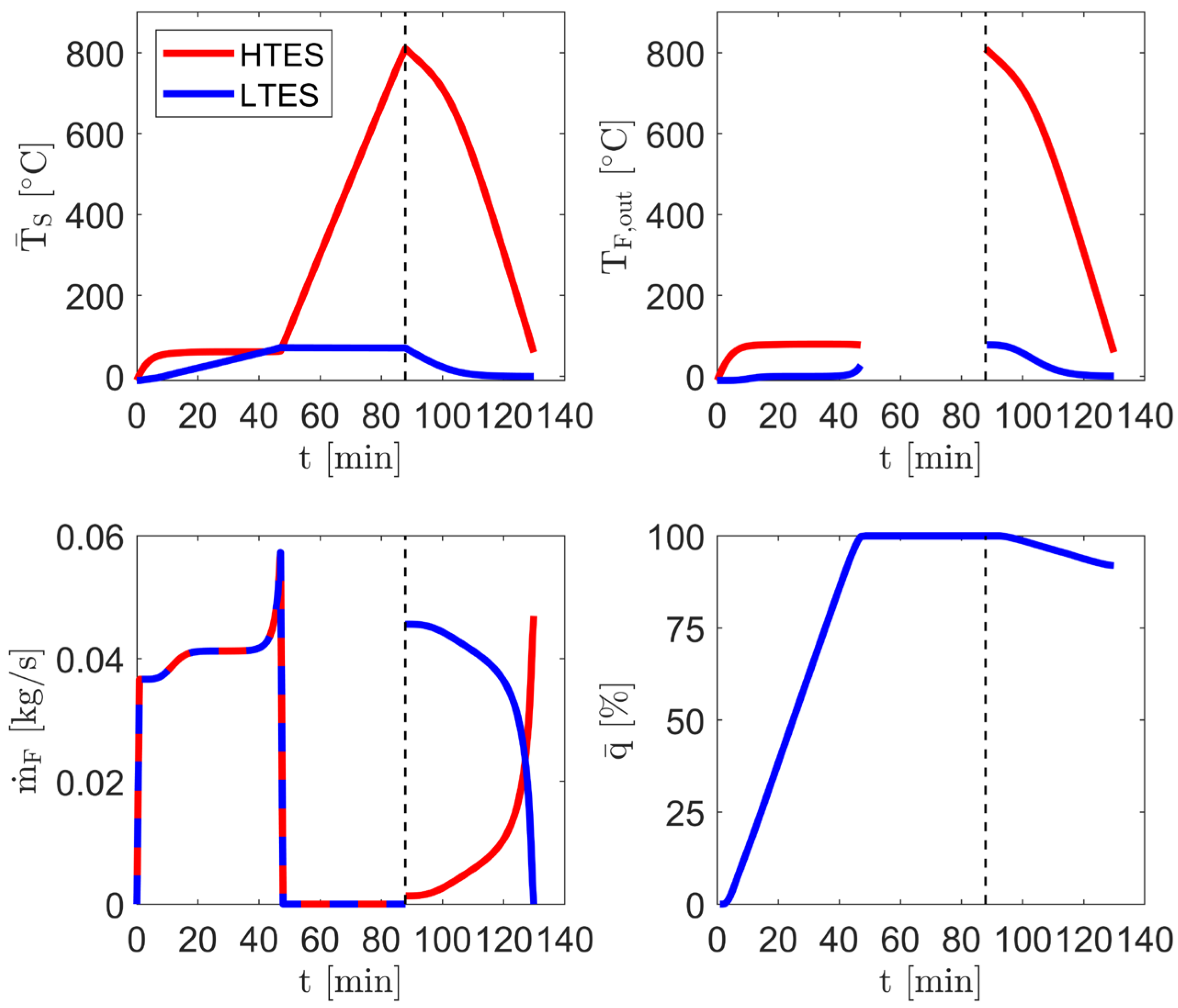
During the charging period in winter (
Figure 10)—as explained in the Introduction—a convective operation takes place first, where the HTES operates in heating mode at a constant power and with maximum HTES outlet temperatures of 80 °C, resulting in the illustrated mass flow rates. Thus, the frozen water in the LTES warms up from its initial state at −10 °C to approx. 70 °C, thereby undergoing a phase change. After charging the LTES (48 min), the mass flow is deactivated and the HTES is heated internally to temperatures of up to 800 °C, maintaining permitted heating wire temperatures of 1000 °C [
14].
During the discharge phase (90 min), the HTF flows exiting the LTES and HTES with elevated temperatures are mixed in a mass flow-controlled fashion in order to achieve the defined constant HTX inlet temperature of 100 °C. The heat provided by the cycle is transferred to the cold ambient air in the HTX and leads to the constant target outlet temperature of 20 °C at 5 kW. At the end of discharging, the thermal energy in the HTES has largely been transferred from the system to the environment, whereas ice formation in the LTES has only just begun. In a directly subsequent charging phase, the resulting time will be reduced, as the initial states have a higher energy content.
In relation to the generated heat during charging and based on initial TES conditions at −10 °C, approx. 72% of the thermal energy was utilized during discharging for BEV air conditioning. This scenario results in heat losses of 1.3% and an available residual heat potential in the TES components of 26.7%.
4.3.2. Storage System for Cooling
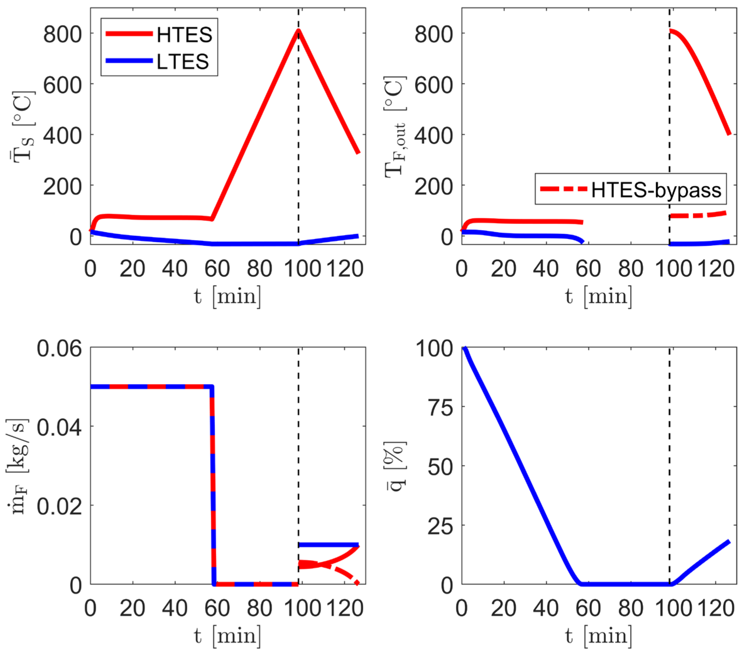
During the charging phase in summer (
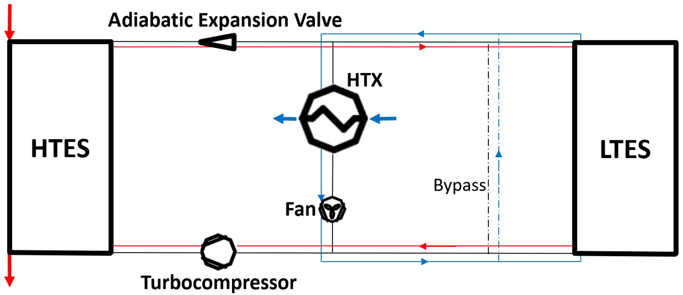
Figure 11), the pressure- and temperature-elevated HTF, at a constant mass flow rate, is cooled down after the turbocompressor to a maximum temperature of 80 °C by the HTES used here as a heat exchanger, whereby the ambient air conducted in the counterflow heats up from 35 °C to a maximum of 95 °C. The cooled compressed HTF is then expanded in the cycle via the adiabatic expansion valve to temperatures of approx. −35 °C, flows through the LTES and leads to a phase change of the initial liquid water. Thus, the constant phase-change temperature plateau at 0 °C is clearly visible in the transient characteristics of the HTF outlet temperature.
Once ice formation in the LTES is completed, the storage system is discharged (60 min). As explained in the Introduction, the LTES is operated in bypass mode and is mass flow-controlled in order to achieve a constant mixing temperature of 5 °C at the inlet of the HTX inside the cycle. During the entire discharging period, the ambient air is thus cooled down from 35 °C to 20 °C constantly with a cooling power of 2.5 kW. At the end, the thermal energy in the LTES has largely been transferred from the system to the environment, and the LTES reaches an average temperature of 22 °C.
In relation to the cold generated during charging and based on initial warm conditions of 35 °C, approx. 89% of the thermal energy is utilized during discharging in summer. This scenario results in heat losses of 0.4% and available residual cold potentials of 10.6%.
4.3.3. Storage System for Power Supply
During the charging period (
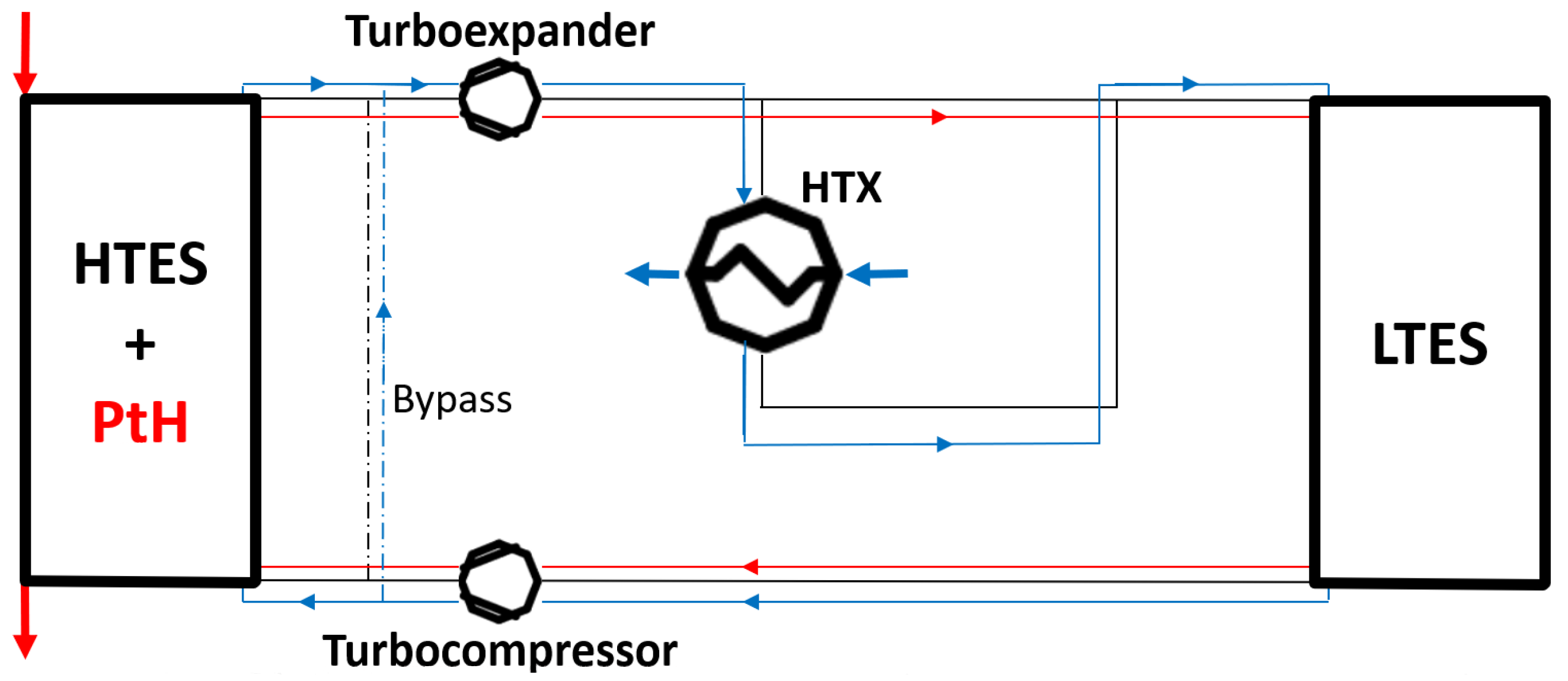
Figure 12), cold is initially generated by the left-handed Brayton cycle process—analogous to summer operation—and stored in the LTES, whereby the initially liquid water freezes and reaches temperatures of approx. −25 °C. Subsequently, the mass flow rate is deactivated and the HTES is heated internally to temperatures of up to 800 °C—analogous to winter operation.
During discharging (95 min), electrical energy is provided via the turboexpander (isentropic efficiency of 80% [
27]) by the right-handed Brayton cycle at the same pressure level (3 bar), whereby a constant turbine inlet temperature of 400 °C is specified for the HTF via the HTES bypass. The HTF leaving the turbine is then cooled by the HTX from 260.4 °C to 75.5 °C, flows through the LTES and reenters the compact turbocompressor at −21 °C on average. Over a discharge period of 28.4 min and at a mass flow rate of 0.01 kg/s, an effective electrical output of 0.34 kW is achieved.
In relation to the thermal energy generated during charging and based on initial conditions of 15 °C, 61% of the thermal energy in the HTES and only 31% in the LTES was utilized for a constant electrical output during discharging. The main reasons for the low TES utilization rates are based on the designed storage system, which was dimensioned for the heating and cooling requirements. However, due to the high thermal energy potential in both TESs, the subsequent charging time would be significantly reduced.
4.4. Discussion
In comparison with operation in winter and summer with effective heating and cooling energies of 3417 Wh (at 5 kW) and 1708 Wh (at 2.5 kW), respectively, it is obvious that a purely electrically driven path with an average discharge work of 166.4 kWh shows significantly lower energy benefits. Although with the same temperature conditions and turbomachinery specifications, higher electrical discharging powers (P) can be reached by increasing mass flow rates (
Table 6), only short-term support in battery electric output is feasible.
With still unused degrees of freedom due to optimized TES geometries or temperature conditions, such a system shows its greatest advantage in storage-supported air conditioning and only limited advantage in short-term electrical support. Despite this, the electrical operation management improves the year-round utilization of the storage system as well as BEV flexibility, particularly through its high dynamic ability and performance, including the integration of previously unused recuperated electrical braking energy.
Due to the very good scalability of the thermal components and the variety of material and manufacturing methods, there is also a large solution space for efficient and cost-effective system configurations for BEV systems with higher performance and capacity requirements. Larger dimensions in particular also improve the performance of such concepts due to lower boundary effects, although there is still potential for optimization in terms of geometry and thermal insulation.
Further development of this technology as a retrofit option or in combination with today’s air conditioning systems is a focus for future activities, particularly for larger BEV systems (busses, trucks, trains, and ships) for efficiency improvements and range increases. Apart from the associated integration options, further simulative and experimental studies are required to address design-critical design aspects. These include questions regarding the durability of the storage components under dynamic loads, techno-economic optimization studies and safety. In addition to the results focused on here with regard to gravimetric storage density, additional studies on volumetric storage density and vehicle system studies will also be necessary to concretize the potential for improvement with regard to BEV range in comparison with conventional HVAC systems.
5. Conclusions
With increasing BEVs, new approaches for improved efficiencies and range extensions are needed. One idea is based on thermal energy storage (TES) systems offering an alternative path for air conditioning and thus conservation of battery capacity. Present TES options have focused widely on heat supply in cold seasons and partially on cold supply in warm seasons. However, holistic concepts for the whole year with high storage densities, performances und utilization rates are required.
To this end, a concept based on a Brayton cycle for a year-round, storage-supported air conditioning system which allows heat and cold supply and, optionally, an electrical energy output was investigated for the first time. Central thermal components include a water/ice-based cold storage (LTES) system, an electrically heated high-temperature solid-media thermal energy storage (HTES) system and a heat exchanger (HTX) whose internal structures are each based on TPMS geometries (Fischer–Koch S). Transient system studies were conducted to identify and evaluate a holistic, matched, storage-supported air conditioning configuration with an HTES mass of 10 kg and an LTES mass of 12.7 kg. The results, considering thermal insulation, show storage densities of up to 100 Wh/kg in winter operation, providing a constant heat supply of 5 kW, with moderately lower storage densities compared to a present reference system designed only for winter (139 Wh/kg), proportionately compensated with a higher discharge time of 41 min (28 min). In summer operation with a constant cooling supply of 2.5 kW, the extended system with identical component specifications and discharge times results in effective storage densities of up to 96 Wh/kg. Due to the underlying Brayton cycle, the system also enables, optionally, an electrical energy output of up to 1.7 kW at times when air conditioning is not required.
Overall, the results show improvements in performance, storage density and operational flexibility in BEVs, which can be realized through multiple use of the thermal central components and the high dynamics of compact turbomachinery. In addition to actual unused optimization potential with regard to TES geometries or temperature ratios, such concepts are particularly suitable for battery electric vehicles with higher capacity, for example, busses, trucks or trains, due to their excellent scalability. Detached from the Brayton cycle taken as a basis here, the knowledge on storage solutions can also be transferred directly to today’s compression air conditioning systems due to comparable interface temperatures. The development of such integration concepts, also as retrofit options, with comparable expected benefits will be focused on in future works and will complement the solution space for the establishment of storage-supported air conditioning paths in BEVs.

