Article

A Direct-Drive Rotary Actuator Based on Modular FSPM Topology for Large-Inertia Payload Transfer

School of Mechanical Engineering, Nanjing University of Science & Technology, Nanjing 210094, China
*
Author to whom correspondence should be addressed.
Energies 2025, 18(19), 5272; https://doi.org/10.3390/en18195272
Submission received: 7 September 2025 / Revised: 29 September 2025 / Accepted: 1 October 2025 / Published: 4 October 2025

Abstract

This paper proposes a novel direct-drive rotary actuator based on a modular five-phase outer-rotor flux-switching permanent magnet (FSPM) machine to overcome the limitations of conventional actuators with gear reducers, such as mechanical complexity and low reliability. The research focused on a synergistic design of a lightweight, high-torque-density motor and a precise control strategy. The methodology involved a structured topology evolution to create a modular stator architecture, followed by finite element analysis-based electromagnetic optimization. To achieve precision control, a multi-vector model predictive current control (MPCC) scheme was developed. This optimization process contributed to a significant performance improvement, increasing the average torque to 13.33 Nm, reducing torque ripple from 9.81% to 2.36% and obtaining a maximum position error under 1 mil. The key result was experimentally validated using an 8 kg inertial load, confirming the actuator’s feasibility for industrial deployment.

1. Introduction

The transition toward large-scale and intelligent manufacturing has established production automation as a crucial strategy for enhancing operational efficiency [1,2,3,4,5,6]. Serving as the core actuating component in automated production and logistics systems, robotic manipulators play a pivotal role in determining overall productivity [7]. However, due to substantial structural dimensions, significant mass, and complex assembly requirements, the design of manipulators for large workpieces should carefully address increased manufacturing complexity, higher maintenance costs, and reduced operational reliability [8,9,10,11]. Consequently, how to balance the performance and the maintenance expenses of large-inertia payload transfer is an essential topic in engineering.
As illustrated in Figure 1, the rotation motion of a conventional large-inertia payload transfer system is achieved by a multi-stage deceleration system. The output power from the high-speed motor is converted to a large output torque by the multi-stage reducer and gearbox. Obviously, such a complex mechanical deceleration device leads to low reliability [12] and increases the mass of the whole system [13]. Fortunately, these limitations can be mitigated by a direct-drive manipulator, as shown in Figure 2. Utilizing an outer-rotor direct-drive machine, the complex mechanical deceleration device can be eliminated to significantly improve systematic integration and position precision.
Extensive research has been conducted in the field of direct-drive systems over the past decade. Heng et al. established direct-drive PMSGs in wind turbines, highlighting key advantages like reduced maintenance and mechanical losses [14]. Dali et al. proposed an improved low-cost controller to enhance the overall viability of direct-drive systems, particularly for small-scale applications [15]. Cai et al. provided a comparative framework for different direct-drive machine topologies, specifically for EV in-wheel applications [16]. Nerg et al. in [17] designed a high-performance direct-drive motor for sports cars, providing valuable insights, such as the handling of cross-saturation effects in inductances and the importance of thermal design for peak torque capability. Although the aforementioned researchers have achieved remarkable progress in direct-drive systems, there is still a lack of studies that address their implementation in industrial settings, where there are strict demands for high integration, exceptional reliability, modular design, and rapid deployment.
To address these design challenges, a novel direct-drive rotary actuator employing a modular five-phase outer-rotor FSPM machine is proposed in this paper. The FSPM machines install both the magnet and armature on the stator, and the robust rotor structure helps to improve the reliability. Moreover, the modular stator has been reconfigured by selectively removing modules to minimize the machine’s weight and accommodate the spatial constraints. All the considerations in the design process are specifically optimized for industrial applications. The following sections are organized as follows: the detailed evolution process of the modular FSPM machine is presented in Section 2, and the electromagnetic optimization is conducted in Section 3 to enhance the output torque characteristics. In Section 4, a multi-vector MPCC strategy is proposed to improve the dynamic performance of the direct-drive system. On this basis, the prototype experiments are carried out in Section 5, and the contributions of this paper are highlighted in Section 6.

2. Machine Topology

In this section, the modular design methodology involves stator reconfiguration of conventional FSPM machines.

2.1. Conventional Five-Phase FSPM Solution

Driven by the requirements of the rotary actuator, the key design parameters of the direct-drive machines are specified in Table 1.
The design selects two slots per pole per phase ( q = 2 ) and one complementary coil group per phase winding ( K = 1 ).
For the C-Core FSPM machine, the number of stator tooth P s c is determined by
  P s c = 2 m K q
where m is the phase number, q refers to the slots per phase and pole, and K denotes the number of complementary coil groups per phase.
To establish the complementarity, the number of rotor poles P r should satisfy [18]
P r = P s c + K
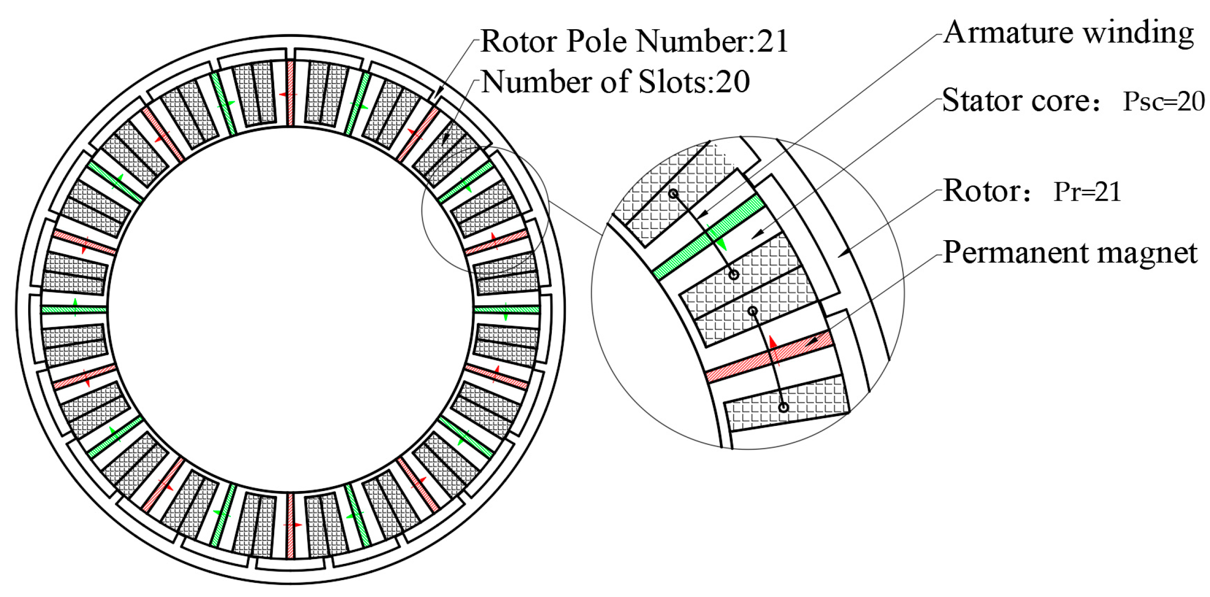
According to (1) and (2), the value of q is set to 2 for the five-phase machine in this paper, P s c is equal to 20, and P r is equal to 21. And the topology of this five-phase 20-slot and 21-pole (20–21) FSPM machine is shown in Figure 3.
The extremely low stack length reduces the structural stiffness of both the stator and rotor, leading to a high risk of mechanical deformation. However, just increasing the stack length is bound to increase the total mass of the manipulator, which then affects the dynamic response of the direct-drive system. Therefore, the design tradeoff must be considered to achieve a synergistic design of stiffness improvement and lightweight through structural innovation while ensuring electromagnetic performance.

2.2. The Stator Module Topology Design of Modular Phase-Unit FSPM

To balance the mass and structural stiffnesses, a modular phase-unit design scheme is proposed in this section. As shown in Figure 4, each phase is independently integrated into one phase-unit to realize the modular design. Through this novel modular phase-unit topology, a modular phase-unit FSPM machine is ultimately constructed. The modular phase-unit FSPM effectively increases the total core length while reducing mass and output torque at the same time per unit thickness. This design strategy significantly enhances the structural stiffness of the motor without substantially increasing its overall mass. This design not only achieves physical isolation and independent maintenance of each phase winding, but also provides greater flexibility for large-scale production and customized applications of the motor [19,20].
Figure 5a illustrates the design process of each modular phase-unit. To optimize the utilization efficiency of permanent magnets, an effective approach is to increase the number of permanent magnets and stator cores within a single module [21], as demonstrated in Figure 5b. However, such a topology exhibits a significant spatial waste, and the slot filling factor is reduced by half.
To address this issue, a modular phase-unit is proposed in this paper by combining the E-shaped and U-shaped stator cores. As shown in Figure 5c, by replacing the central U-shaped stator core with an E-shaped one, the volume of the proposed modular phase-unit is slashed sharply, and the slot area can be completely employed. This hybrid core layout enhances electromagnetic performance while ensuring optimal space utilization of winding slots.
However, the 5–21 pole modular phase-unit FSPM obtained by removing adjacent stator cores from a conventional 20–21 pole conventional FSPM lacks structural complementarity. As a result, it does not retain the advantage of the low-torque ripple characteristic of FSPM. According to the design theory of flux-switching machines, when K = 1 , the number of complementary coil pairs per phase (or per pole pair) is 1. Consequently, each phase must be composed of two modules. To achieve a five-phase modular phase-unit FSPM with complementary characteristics, at least 10 modules are required, meaning that the original E-shaped FSPM must have a stator tooth number P s c of at least 40.

2.3. Topology Design of Modular 5-Phase FSPM

As shown in Figure 6, the design process of the 5-phase modular phase-unit FSPM is as follows:
Design a conventional E-shaped stator core FSPM.
Parameter Transformation After Completion Operation:
  • Number of Phases m = 5 ;
  • Slots per pole per phase q = 4 ;
  • Complementary coil groups per phase K = 1 .
Parameter Calculation Based on E-Core FSPM Design Principle:
The number of stator tooth P s c is
  P s c = 2 m K q = 40
The number of rotor poles P r   of the E-shaped stator cores FSPM is [22]
P r = 2 P s c + K = 81
In the structure shown in Figure 6a, each phase of the motor contains four windings. The stator core and permanent magnets wound by the two middle windings are retained to form one stator module. The removal of the remaining outer parts allows mutual separation between different stator modules.
Replace the E-shaped stator cores at the edges of each module with U-shaped stator cores. Based on the structural characteristics of the motor with P r = 81 rotor poles, each stator module can be theoretically rotated by θ = 360 ° / 81 4.44 ° along the axial direction without altering the fundamental electromagnetic operating principles [23].
As a result, the design procedure for the modular 5-phase FSPM motor is as follows:
(1)
First, obtain the complete topology of a five-phase E-core FSPM motor, as shown in Figure 6a.
(2)
By removing the complementary stator modules, the structure shown in Figure 6b is obtained.
(3)
The final topology in Figure 6c is achieved by substituting E-core configurations with U-cores at modular boundaries, optimizing both structural integrity and magnetic circuit performance.
This paper conducts rotational adjustment of the stator modules, illustrated in Figure 6d, to bring the modules closer together to form two large stator modules. The quality of the motor stator bracket is further reduced, and the structural compactness is improved. The manipulator structure designed based on this motor topology is shown in Figure 7.

3. Optimization of Electromagnetic Performance

3.1. Main Mechanical Size Design

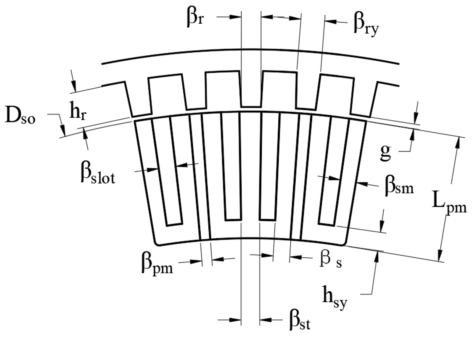
In Figure 8, the main mechanical size of the stator is given. g is the unilateral air-gap length, β r is the rotor tooth width, β r y is the width of the connecting part of the rotor tooth and the rotor yoke, h r is the rotor tooth height, β s is the stator tooth width, β s l o t is the stator slot width, β s t is the auxiliary stator tooth width, β s m is the marginal stator tooth width, β p m is the PM width and lpm is the PM length, and h s y is the height of the stator yoke.
According to the design methodology of E-core FSPM machines, the design parameters are determined as follows:
  β r = β r y = β s = β s l o t = β s t = β s m = β p m = 360 6 P s c
  h s y = h r = Π D r o 6 P s c
Finally, the initial model parameters of the motor are obtained, as shown in Table 2.

3.2. Optimization Procedure

Based on the initial model parameters shown in Table 2, a transient FEA model was established in JMAG 20.0 software for optimization design. The mesh size for both the stator and rotor is set to 2 mm. A sliding mesh interface is applied between them, with the number of mesh elements set to five times the least common multiple of the number of rotor poles and stator teeth, which is 4200. The remaining air regions are meshed with a size of 5 mm. The rotor operates at a speed of 43 rpm. The simulation runs for two electrical cycles, calculated as 2 × 60/43/81 ≈ 0.035 s. The stator and rotor core material is defined as 50CS470H, and the permanent magnets are of grade N35. The mesh and material properties are illustrated in Figure 9. The waveforms of the no-load flux linkage, no-load back electromotive force (EMF), and output torque of the initial motor model are shown in Figure 10. It should be noted that all the waveforms were obtained under a single-turn coil. It can be seen that the back EMF contains fruitful harmonics, and the torque ripple is as high as 9.81%. Obviously, the initial design cannot meet the operational requirement, and the optimization process is necessary.
The optimization objectives are to reduce torque ripple and increase output torque. The optimization parameters include the stator inner diameter Dsi , split ratio k s i o , rotor-side parameters, and stator-side parameters. The rotor-side parameters include the rotor tooth width β r , rotor tooth coefficient kry   ( βry / βr ) , and rotor tooth height h p r . The stator-side parameters include the stator tooth width βs , stator slot width β s l o t , auxiliary stator tooth width β s t , marginal stator tooth width β s m , permanent magnet angle β p m , and stator yoke width h s y . In JMAG, set the optimization range and step size for the aforementioned parameters. The output torque and torque ripple under different parameter values are calculated to determine the optimal value for each parameter. Two optimization runs are performed by adjusting the sequence of the parameters, thereby finalizing the optimal design parameters for the motor. The optimization ranges and step sizes for each parameter are presented in Table 3.
The optimized motor performance parameters are shown in Figure 11, where torque ripple is reduced from 9.81% to 2.36%, and the average output torque increases from 12.02 Nm to 13.33 Nm. The dimensional parameters of the optimized motor are presented in Table 4.

4. The Proposed Control Strategy

This study presents an innovative multi-vector MPCC approach that establishes the mathematical correlation between duty-cycle vectors and virtual voltage vectors across various coordinate systems. As illustrated in Figure 12, the implementation framework comprises five key components: delay compensation, current bias computation, cost function minimization, duty-cycle transformation, and duty-cycle regeneration.

4.1. Modeling of Five-Phase FSPM Motor

Figure 13 illustrates the proposed minimalistic circuit configuration, which employs five full-bridge inverters to control the FSPM machine, considering both fundamental and third-order harmonic subspace [24].
The voltage equation is expressed as follows:
    u d = R s i d + L d d i d d t ω e L q i q                 u q = R s i q + L q d i q d t + ω e L d i d + ω e ψ f u d 3 = R s i d 3 + L d 3 d i d 3 d t 3 ω e L q 3 i q 3   u q 3 = R s i q 3 + L q 3 d i q 3 d t + 3 ω e L d 3 i d 3
And the torque equation is expressed as follows:
T e = 5 2 P n ψ f i q + L d L q i d i q + 3 L d 3 L q 3 i d 3 i q 3
The variables i d ,   i q ,   u d ,   u q ,   L d ,   L q represent the current, voltage, and inductance in fundamental rotating reference frames while i d 3 ,   i q 3 ,   u d 3 ,   u q 3 ,   L d 3 ,   L q 3 represent the current, voltage, and inductance in the third-order harmonic rotating reference frames. The variables R s ,   T e ,   P n ,   ω e ,   ψ f represents stator resistance, electromagnetic torque, pole pair numbers, electrical angular velocity, and permanent magnet flux linkage, respectively.

4.2. Current Bias Computation and Delay Compensation

According to the first-order Euler discretization, the current at ( k + 1 ) sampling period should be
i d k + 1 = 1 R s T s L d i d k + ω e T s L q L d i q k + T s u d k L d   i q k + 1 = 1 R s T s L q i q k ω e T s L d L q i d k ω e T s ψ f L q + T s u q k L q
where T s denotes the sampling duration, with x k indicating the sampled state at time step k and x k + 1 representing its one-step-ahead prediction.
The MPCC approach formulates the state regulation problem as an optimization task that equals to minimize the objective function specified in (10).
  J = i d * i d k + 1 2 + i q i q k + 1 2
By iegrating Equations (9) and (10), the optimization can be transformed as:
J = i d k     | u 0 T s L d u d k 2 + i q k     | u 0 T s L q u q k 2
where i d k     | u 0 and i q k     | u 0 are the current tracking bias when input voltage equals zero, which is shown in Equation (12).
i d k     | u 0 = i d 1 R s T s L d i d k ω e T s L q L d i q k i q k     | u 0 = i q 1 R s T s L q i q k + ω e T s L d L q i d k + ω e T s ψ f L q
There is always have a small time-gap between when a command is given and when the motor acts in control systems. To address this problem, smart control methods use prediction to guess the next act of motor and change the commands ahead of time. The delay compensation equation should be:
J = i d k + 1     | u 0 T s L d u d k 2 + i q k + 1     | u 0 T s L q u q k 2

4.3. Cost Function Minimization

According to the pulse width modulation (PWM) theory, the voltage relationship can be mathematically expressed using α β axis duty cycle d α and d β as:
    u α k u β k = v × d α k d β k
where v represents the magnitude of vectors in virtual voltage vector space.
Combining the Park transformation with Equations (13) and (14), Equation (13) can be rewrite as follows:
J = i d k + 1     | u 0 v T s L d c o s θ e d α k + s i n θ e d β k 2 + i q k + 1     | u 0 v T s L q s i n θ e d α k + c o s θ e d β k 2
Calculate the partial derivatives of the cost function for both d α and d β components [25]:
  J d α k = 0 J d β k = 0
The solution of Equation (16) yields the final expressions for d α and d β :
          d α k = L d i d k + 1     | u 0 c o s θ e L q i q k + 1     | u 0 s i n θ e v T s d β k = L q i q k + 1     | u 0 c o s θ e + L d i d k + 1     | u 0 s i n θ e v T s

4.4. Duty-Cycle Transformation

Despite Clarke transformation matrix shown as Equation (18) is commonly applied to convert voltages, currents and other electrical quantities into α − β coordinates, its use for duty-cycle vector transformation has received limited research attention. This novel application presents significant theoretical benefits.
T C l a r k e = 1 0 c o s δ   s i n δ   c o s 2 δ   s i n 2 δ   c o s 3 δ s i n 3 δ c o s 4 δ   s i n 4 δ
where δ = 2 π / 5 in five phase FSPM motor.
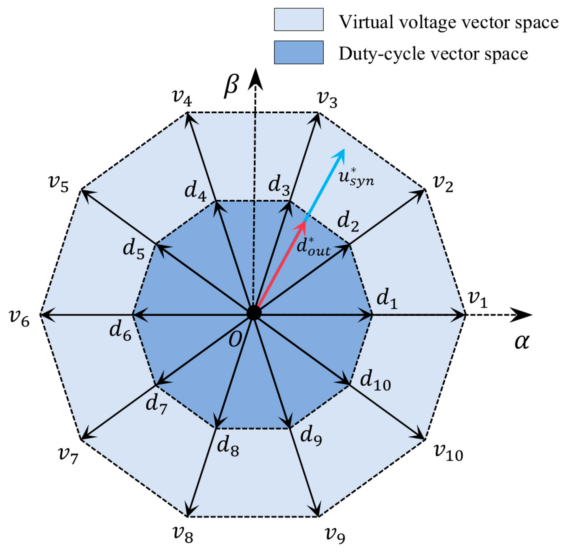
As illustrated in Figure 14, the virtual voltage vector space and duty-cycle vectors lie on the same plane. These vectors keep exactly matching angles and scaled magnitudes. For calculation convenience, the duty-cycle vectors are expressed as:
  d α β = d α d β T d ~ A B C D E = d ~ A d ~ B d ~ C d ~ D d ~ E T
where d ~ A B C D E denotes the virtual duty cycle for regeneration. Based on coordinate transformation and PWM theory, the following formulations hold obviously.
u α β = T C l a r k e u A B C D E
u A B C D E = v d ~ A B C D E
By integrating Equations (14), (20) and (21), the transformation between phase and α β coordinates can be expressed as:
d ~ A B C D E = T C l a r k e 1 d α β

4.5. Duty-Cycle Regeneration

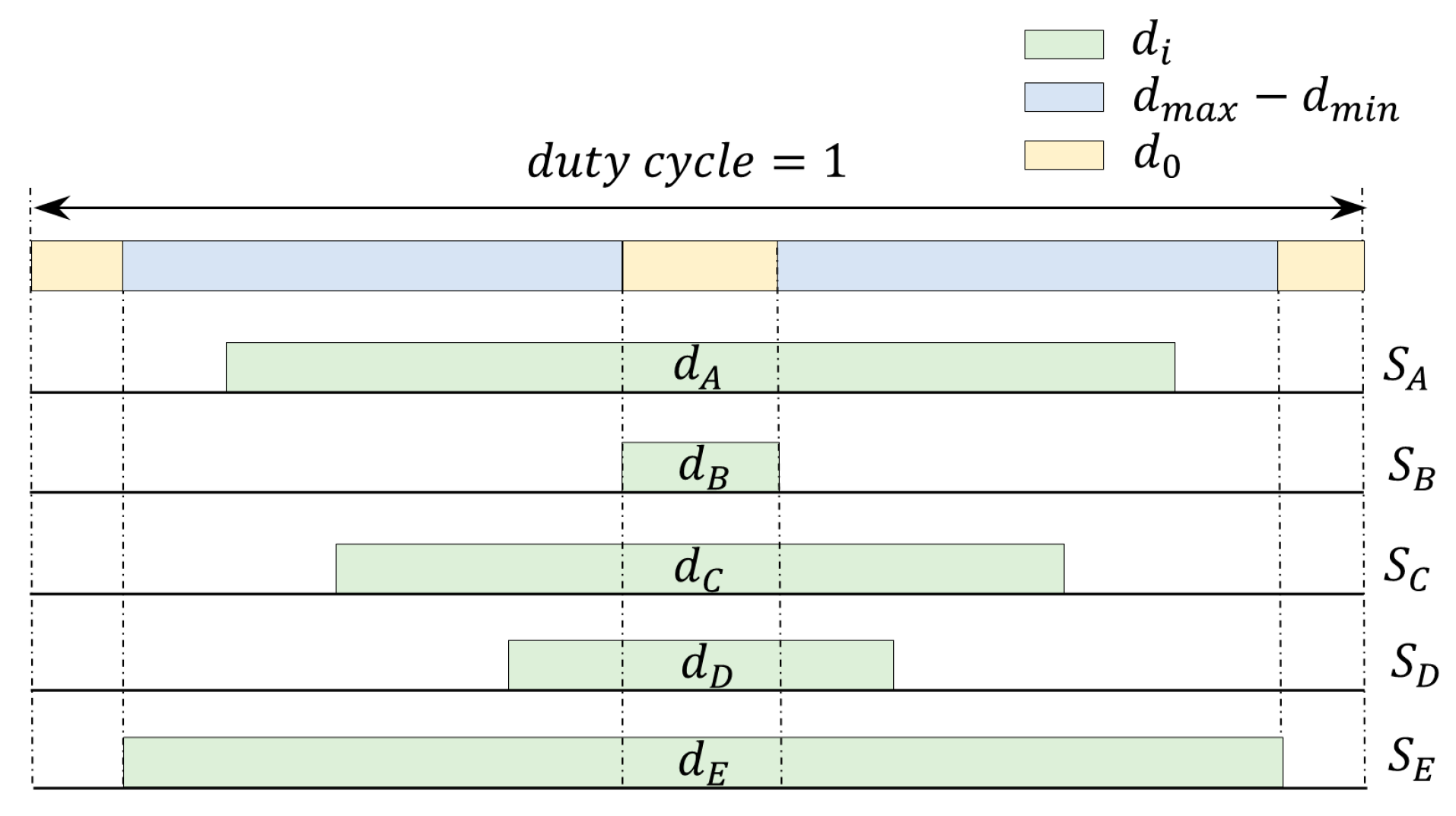
In practical implementations, the multi-vector MPCC requires zero-vector inclusion for precise current regulation. However, the computed duty cycles may exceed valid ranges ( 0     d     1 ) when the synthesized virtual voltage vector magnitude surpasses ‖v‖ or becomes negative, which is an unacceptable condition for high-precision drives. Figure 15 presents the proposed duty-cycle regeneration solution.
Assuming a normalized PWM period (1 s for simplicity), d 0 should be complement to ( d m a x d m i n ). Three invalid cases require correction: (1) when d m a x > 1, (2) when d m i n < 0, and (3) when ( d m a x     d m i n ) > 1. In this paper, a rectified linear unit ( R e L U ) function is applied to enforce d 0 within [0,1] as follows:
d m a x = max d ~ A , d ~ B , d ~ C , d ~ D , d ~ E             d m i n = min d ~ A , d ~ B , d ~ C , d ~ D , d ~ E             d 0 = R e L U 1 d m a x d m i n    
Following zero-vector duty-cycle computation, the remaining switching time is proportionally distributed among all five phases, as follows:
  d i = 1 d 0 d ~ i d m i n d m a x d m i n , i = A , B , C , D , E

5. Experiment Validation

5.1. Machine Manufacturing

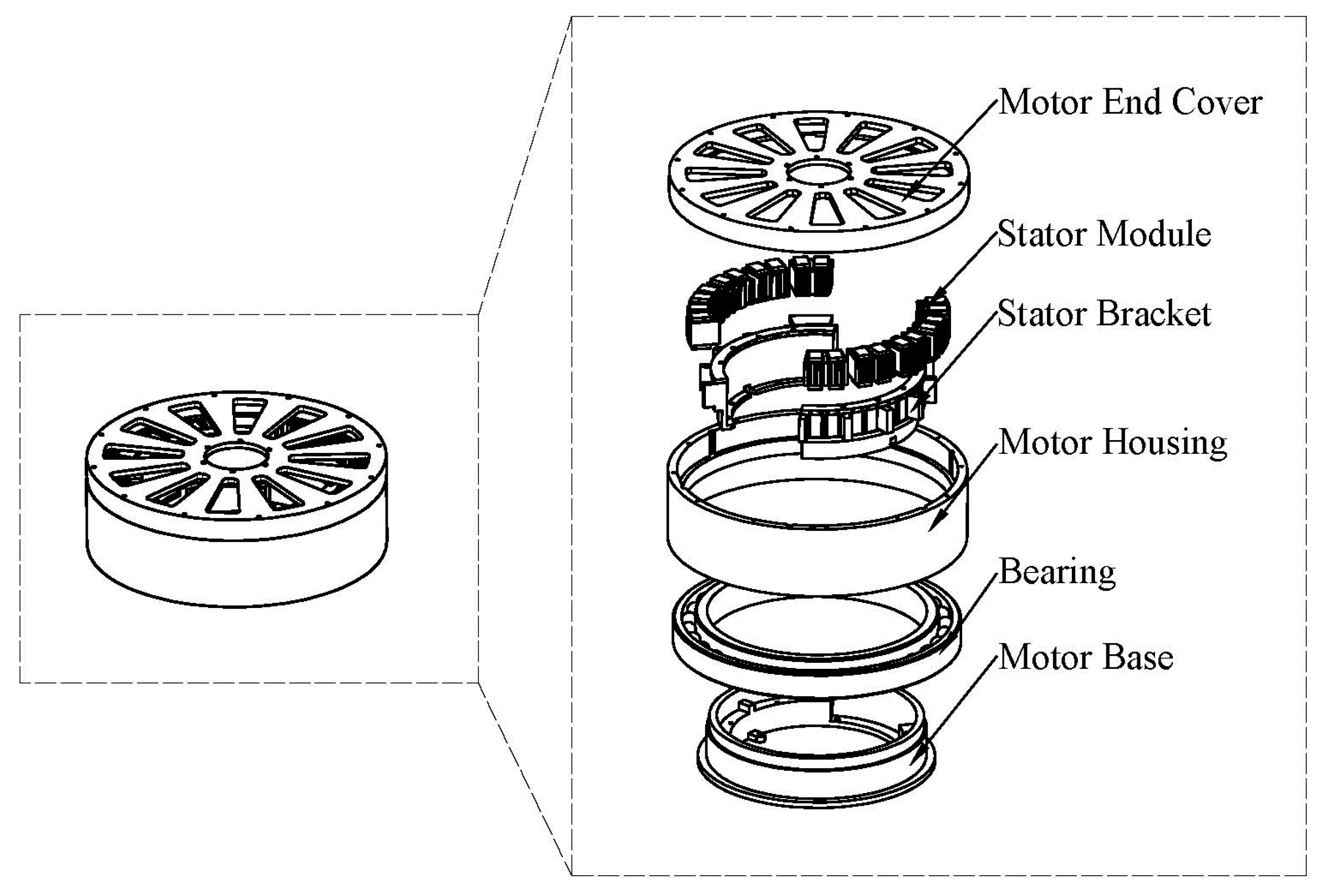
To validate the proposed design and control methods, the prototype of five-phase modular phase-unit FSPM machine is manufactured, as shown in Figure 16. The rotary actuator is primarily composed of key components such as the motor end cover, stator module, stator bracket, motor housing, bearings, and motor base, among these, the motor end cover, stator module, stator bracket, motor housing, and motor base are all precision-machined from 6061 aluminum alloy, a material renowned for its excellent strength-to-weight ratio and machinability [26].
In terms of structural design, a modular layout scheme is adopted, with precisely five stator modules configured on each side. These modules are securely fixed via detachable stator brackets. This innovative modular design enables efficient maintenance or replacement of stator modules even after the complete assembly of the motor unit, as the stator brackets can be quickly disassembled. This approach significantly enhances equipment maintainability while substantially reducing overall system maintenance complexity. Such a design is particularly suitable for industrial applications requiring frequent servicing [27].
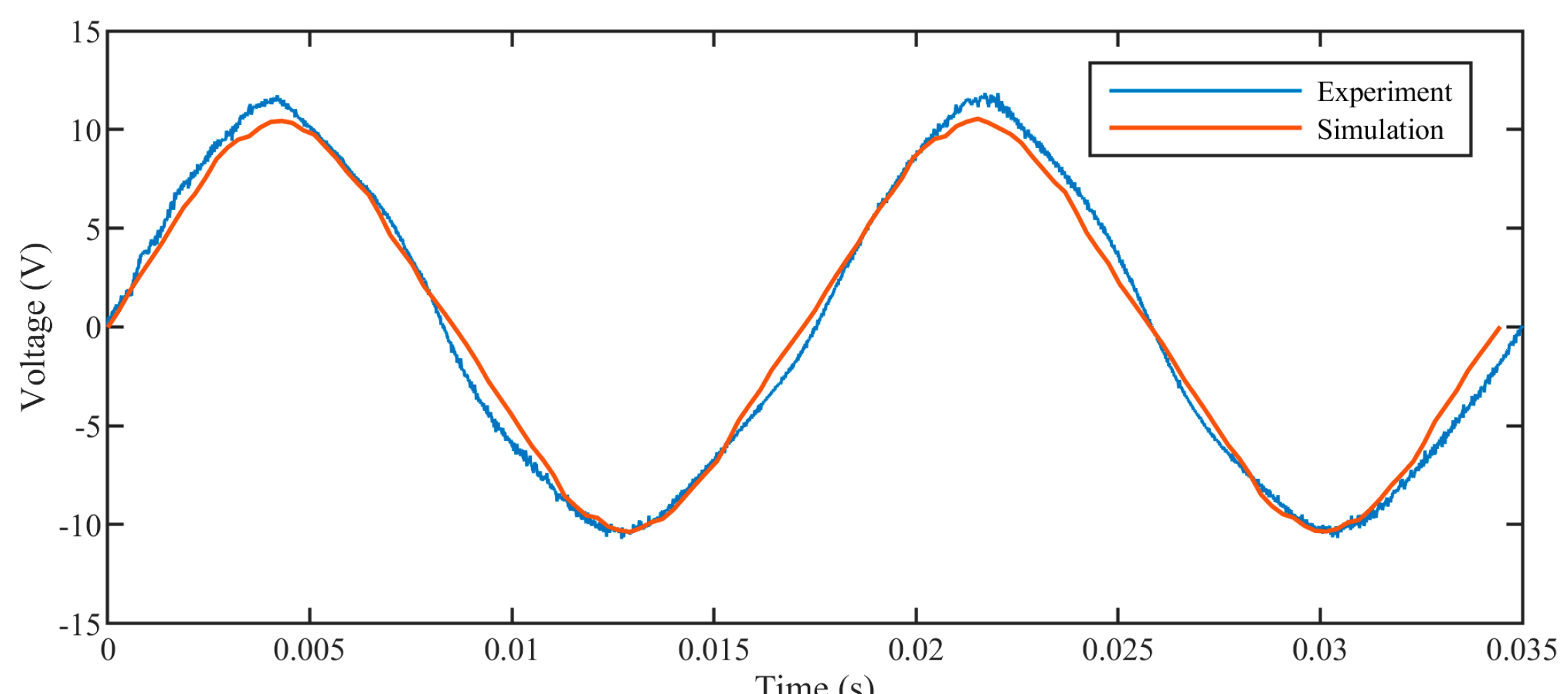
To validate the machine’s manufacturing correctness, back EMF and rated torque load experiments were conducted. As shown in Figure 17, the experimental back EMF waveform has a peak-to-peak value of 22.59 V, which compares well with the simulated value of 20.93 V. Similarly, under rated torque load (Figure 18), the experimental five-phase currents measure 5.42 A peak-to-peak, closely matching the simulation result of 5.26 A. The discrepancy may originate from the design and assembly process. In general, the results fall within an acceptable range.

5.2. Experiment Platform Establishment

The parameters of this five-phase FSPM motor are shown in Table 5 and the test configuration is illustrated in Figure 19, where the motor is mechanically connected to a large-inertia material load, along with control hardware, a multi-phase power converter, and an adjustable DC source. The Implementation utilized a 200 MHz TMS320F28379D dual-core DSP for real-time control, operating at 10 kHz PWM frequency with 24 V bus voltage.
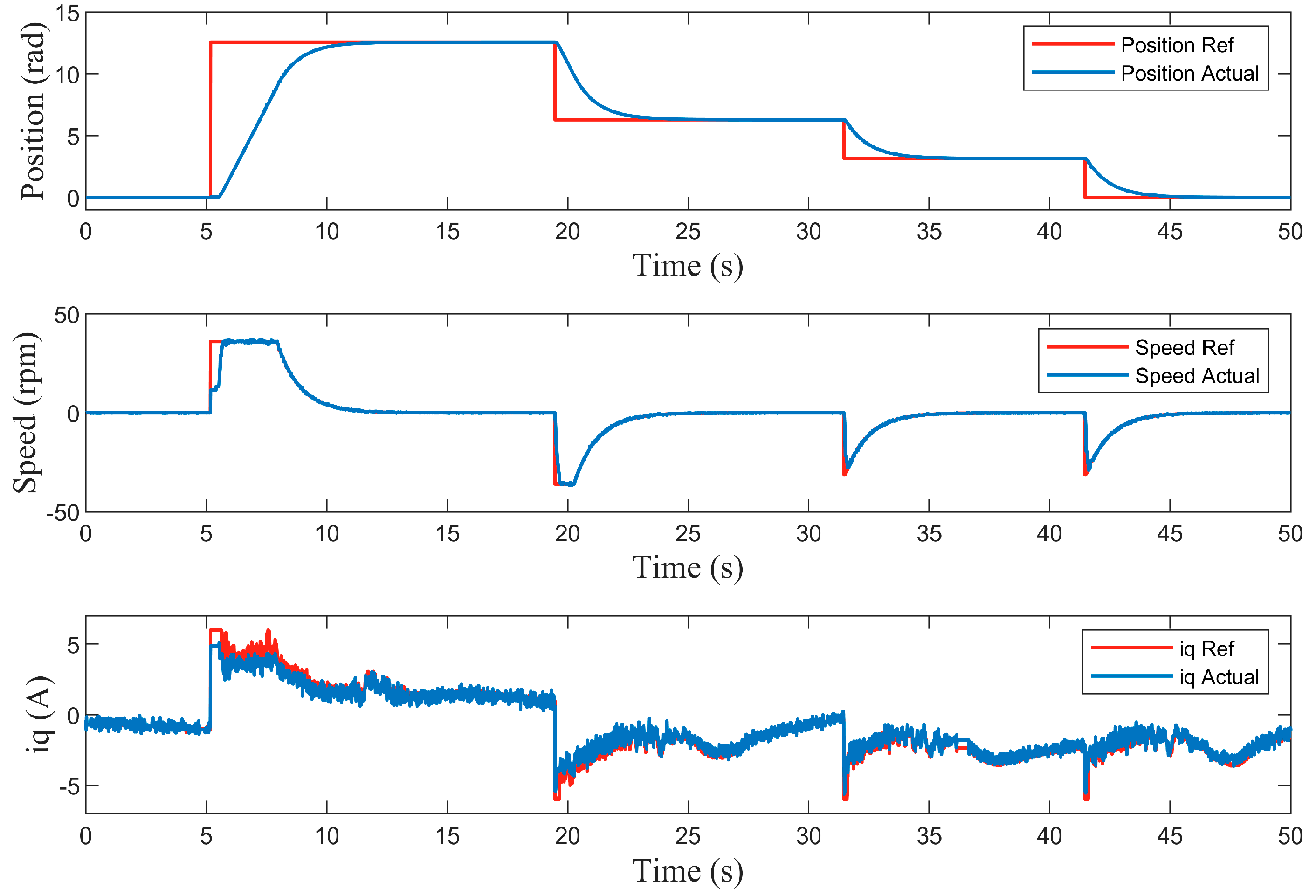
The position control performance of the proposed system was experimentally evaluated through a series of step response tests. The evaluation involved sequentially commanding four distinct reference positions: 4 π radian, 2 π radian, π radian, and finally returning to zero home position. Regarding the five-phase current waveforms as shown in Figure 20, the peak current in the startup reaches approximately 6 A, and decreases to around 4 A during the acceleration, further reduces to about 2 A in the constant velocity, and finally stop at home position.
The corresponding position, speed and i q waveforms are shown in Figure 21. The entire position tracking process consists of four stages: startup, acceleration, constant velocity, and deceleration. Concerning the position loop, the motor tracks and reaches the target position of 4π radians within 15 s. Subsequently, it returns to 2π and π radian positions, and finally to the initial zero position, with each transition completed within a 10 s interval. The entire process is characterized by a smooth tracking performance without any overshoot. Concerning the speed loop, the motor demonstrates excellent tracking performance by following the target speed during each positioning sequence. It effectively accomplishes the tasks of acceleration, maintaining constant velocity, and deceleration. Concerning the current loop, the q-axis current exhibits minimal fluctuation and a rapid dynamic response, ensuring precise and stable torque control throughout the operation. Position tracking error under different targets as shown in Table 6 indicates that the maximum positioning error is less than 1 mil.
Comprehensive test data above revealed that the developed drive system consistently attained all target positions with remarkable positioning precision, even when subjected to significant inertial loading of 8 kg, which effectively satisfies the modern industrial automation systems. Furthermore, the system exhibited excellent repeatability during multiple test cycles, demonstrating its reliability for continuous production line operations. These experimental outcomes confirm that the proposed control scheme successfully addresses the critical challenges associated with large-inertia rotary actuator in industrial settings.

6. Conclusions

This paper proposed a comprehensive solution for high-performance design and control of direct-driven modular rotary actuator system. Through the integration of a modular phase-unit FSPM motor and an advanced MPCC strategy, the proposed system addresses critical challenges in industrial automation, including structural rigidity, dynamic response, and precision control. Compared with the conventional design, the optimized motor achieved a rated torque of 13.33 Nm with a significantly reduced torque ripple of 2.36%, and a maximum positioning error under 1 mil, even under a high-inertia load of 8 kg. The experimentally validated results confirm the solution’s feasibility for industrial deployment where precision and reliability are critical. A recognized limitation of the current study is the absence of a thorough thermal analysis under continuous loading conditions. Therefore, future work will focus on thermal modeling and management, as well as enhancing the fault-tolerant capability of the drive system to further improve its robustness for industrial deployment.

Author Contributions

Conceptualization, M.T. and L.Q.; methodology, J.Z., Z.W. and M.T.; software, J.Z. and Z.W.; validation, J.Z., Z.W. and M.T.; formal analysis, M.T. and L.C.; investigation, J.Z. and Z.W.; resources, M.T., L.C. and L.Q.; data curation, J.Z. and Z.W.; writing—original draft preparation, J.Z. and Z.W.; writing—review and editing, M.T.; visualization, J.Z., Z.W. and M.T.; supervision, M.T.; project administration, M.T.; funding acquisition, M.T., L.C. and L.Q. All authors have read and agreed to the published version of the manuscript.

Funding

This research was funded by the National Natural Science Foundation of China (NSFC), grant number 52307059, and the Fundamental Research Funds for the Central Universities, grant number 30923010901.

Data Availability Statement

Data are contained within the article.

Conflicts of Interest

The authors declare no conflicts of interest.

References

  1. Yang, T.; Yi, X.; Lu, S. Intelligent manufacturing for the process industry driven by industrial artificial intelligence. Engineering 2021, 7, 1224–1230. [Google Scholar] [CrossRef]
  2. Liu, X.; Cheng, Q.; Guo, K. Influencing Factors of Intelligent Manufacturing: Empirical Analysis Based on SVR Model. Procedia Comput. Sci. 2017, 122, 1024–1030. [Google Scholar] [CrossRef]
  3. Zhou, Y.; Zang, J.; Miao, Z.; Minshall, T. Upgrading Pathways of Intelligent Manufacturing in China: Transitioning across Technological Paradigms. Engineering 2019, 5, 691–701. [Google Scholar] [CrossRef]
  4. Zeng, X.; Li, C.; Li, X.; Mao, C.; Li, Z.; Li, Z. Energy Efficiency Optimization of Air Conditioning Systems Towards Low-Carbon Cleanrooms: Review and Future Perspectives. Energies 2025, 18, 3538. [Google Scholar] [CrossRef]
  5. Rojek, I.; Mikołajewski, D.; Kopowski, J.; Bednarek, T.; Tyburek, K. Energy Efficiency and Sustainability of Additive Manufacturing as a Mass-Personalized Production Mode in Industry 5.0/6.0. Energies 2025, 18, 3413. [Google Scholar] [CrossRef]
  6. Różycki, R.; Solarska, D.A.; Waligóra, G. Energy-Aware Machine Learning Models—A Review of Recent Techniques and Perspectives. Energies 2025, 18, 2810. [Google Scholar] [CrossRef]
  7. Li, B.; Li, X.; Gao, H.; Wang, F. Advances in Flexible Robotic Manipulator Systems—Part I: Overview and Dynamics Modeling Methods. IEEE Trans. Mechatron. 2024, 29, 1100–1110. [Google Scholar] [CrossRef]
  8. Pistone, A.; Ludovico, D.; De Mari Casareto Dal Verme, L. Modelling and control of manipulators for inspection and maintenance in challenging environments: A literature review. Annu. Rev. Control. 2024, 57, 100949. [Google Scholar] [CrossRef]
  9. Friederich, J.; Lazarova-Molnar, S. Reliability assessment of manufacturing systems: A comprehensive overview, challenges and opportunities. J. Manuf. Syst. 2024, 72, 38–58. [Google Scholar] [CrossRef]
  10. Tao, B.; Gong, Z.; Ding, H. Robotic cluster machining: Manufacturing revolution for large and complex components. Sci. China Technol. 2022, 65, 2215–2217. [Google Scholar] [CrossRef]
  11. Recker, T.; Heilemann, F.; Raatz, A. Handling of large and heavy objects using a single mobile manipulator in combination with a roller board. Procedia CIRP 2021, 97, 21–26. [Google Scholar] [CrossRef]
  12. Zhu, J.; Tong, M.; Wang, Z.; Chen, L.; Xu, Z. Investigation of a vector-controlled dual 5-phase motor driving system in artillery automatic loading applications. In Proceedings of the International Conference on Defence Technology, Xi’an, China, 23–26 September 2024. [Google Scholar]
  13. Wang, Z.; Tong, M.; Zhu, J.; Chen, L.; Xu, Z.; Huangfu, B. Optimization design of a dual 5-phase flux-switching permanent-magnet machine for a direct-drive manipulator in artillery automatic loading applications. In Proceedings of the International Conference on Defence Technology, Xi’an, China, 23–26 September 2024. [Google Scholar]
  14. Heng, T.; Ding, T.; Chang, C.; Ping, T.; Yian, H.; Dahari, M. Permanent Magnet Synchronous Generator design optimization for wind energy conversion system: A review. Energy Rep. 2022, 8, 277–282. [Google Scholar] [CrossRef]
  15. Dali, A.; Abdelmalek, S.; Bakdi, A.; Bettayed, M. A new robust control scheme: Application for MPP tracking of a PMSG-based variable-speed wind turbine. Renew. Energy 2021, 172, 1021–1034. [Google Scholar] [CrossRef]
  16. Cai, S.; Kirtley, J.; Lee, C. Critical Review of Direct-Drive Electrical Machine Systems for Electric and Hybrid Electric Vehicles. IEEE Trans. Energy Convers. 2022, 37, 2657–2668. [Google Scholar] [CrossRef]
  17. Nerg, J.; Rilla, M.; Ruuskanen, V.; Pyrhonen, J.; Ruotsalainen, S. Direct-Driven Interior Magnet Permanent-Magnet Synchronous Motors for a Full Electric Sports Car. IEEE Trans. Ind. Electron. 2014, 61, 4286–4294. [Google Scholar] [CrossRef]
  18. Zhao, G. Research on Key Issues of Flux-Switching Machines. Ph.D. Thesis, Southeast University, Nanjing, China, 2019. [Google Scholar]
  19. Sermeno, B.; Santos, R.; Tria, L. Modeling of a Modular Stator Segmented Rotor Switched Reluctance Motor for Circuit Simulation. In Proceedings of the International Power Electronics Conference, Himeji, Japan, 15–19 May 2022. [Google Scholar]
  20. Mese, E.; Yasa, Y.; Ertugrul, B.; Sincar, E. Design of a high performance servo motor for low speed high torque application. In Proceedings of the International Conference on Electrical Machines (ICEM), Berlin, Germany, 2–5 September 2014. [Google Scholar]
  21. Khoshoo, B.; Aggarwal, A.; Barron, M.; Foster, S.N. Analysis of Segmented Stator and Rotor Design in PMSM Using a Physics-Based MEC Model. In Proceedings of the 2024 IEEE Energy Conversion Congress and Exposition (ECCE), Phoenix, AZ, USA, 20–24 October 2024; pp. 5240–5246. [Google Scholar]
  22. Zhang, H. Analysis and Design of a Novel Fractional-Slot Concentrated-Winding Permanent Magnet Hub Motor. Master’s Thesis, Southeast University, Nanjing, China, 2020. [Google Scholar]
  23. Wang, L.; Wang, X. Torque Ripple Analysis and Reduction of Interior Permanent Magnet Synchronous Motors. IEEE Trans. Appl. Supercond. 2024, 34, 1–5. [Google Scholar] [CrossRef]
  24. Hua, W.; Chen, F.; Huang, W.; Zhang, G.; Wang, W.; Xia, W. Multivector-Based Model Predictive Control with Geometric Solution of a Five-Phase Flux-Switching Permanent Magnet Motor. IEEE Trans. Ind. Electron. 2020, 67, 10035–10045. [Google Scholar] [CrossRef]
  25. Wu, X.; Zhang, Y.; Shen, F.; Yang, M.; Wu, T.; Huang, S. Equivalent Three-Vector-Based Model Predictive Control with Duty-Cycle Reconstruction for PMSM. IEEE Trans. Ind. Electron. 2024, 71, 2395–2404. [Google Scholar] [CrossRef]
  26. Gao, Y.; Dong, B.; Yang, H. Research progress, application and development of high performance 6000 series aluminum alloys for new energy vehicles. J. Mater. Res. Technol. 2024, 32, 1868–1900. [Google Scholar] [CrossRef]
  27. Wu, Q.; Wang, L.; Yang, G.; Tang, E. Structural design and performance prediction of novel modular tubular permanent magnet linear synchronous motor. J. Magn. Magn. Mater. 2022, 564, 170158. [Google Scholar] [CrossRef]
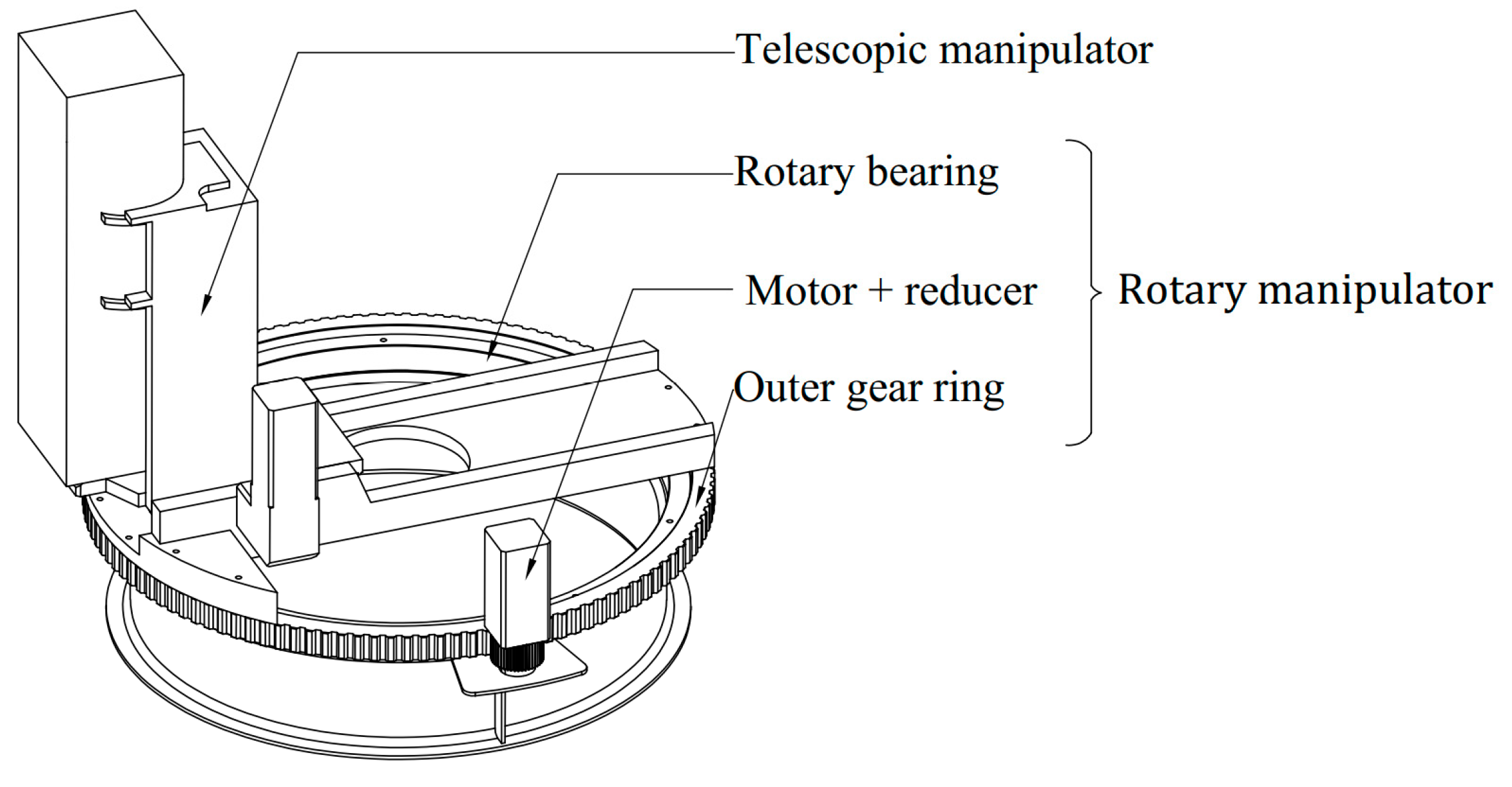
Figure 1. A schematic of a conventional decelerate-drive manipulator utilizing a geared drive system. The rotary manipulator consists of a high-speed motor, a gear reducer, a rotary bearing, and an outer gear ring.
Energies 18 05272 g001
Figure 2. A schematic of the proposed direct-drive manipulator, illustrating the novel design that replaces the complex gearbox from Figure 1 with a compact, modular outer-rotor FSPM motor integrated directly. The proposed design reduces mechanical complexity and improves position precision.
Energies 18 05272 g002
Figure 3. Topology illustration of the 20–21 FSPM machine.
Energies 18 05272 g003
Figure 4. Topology of FSPM motor with reduced number of stator cores.
Energies 18 05272 g004
Figure 5. Optimization of segmented stator structure. (a) Single permanent magnet C-shaped module. (b) Dual permanent magnet C-shaped module. (c) Dual permanent magnet hybrid core module.
Energies 18 05272 g005
Figure 6. Machine topology. (a) Conventional E-shaped stator core FSPM. (b) C-shaped stator core modular phase-unit FSPM. (c) Hybrid stator core modular phase-unit FSPM. (d) Adjust the relative positions of each module.
Energies 18 05272 g006
Figure 7. Designed structure of proposed manipulator.
Energies 18 05272 g007
Figure 8. Stator and rotor structure dimensions.
Energies 18 05272 g008
Figure 9. Simulation parameter settings. (a) Mesh settings. (b) Permanent magnet material parameters. (c) Silicon steel sheet material parameters.
Energies 18 05272 g009
Figure 10. Performance of initial parameter motor.
Energies 18 05272 g010
Figure 11. Optimized machine performance parameters.
Energies 18 05272 g011
Figure 12. The control scheme of the proposed MPCC.
Energies 18 05272 g012
Figure 13. The circuit topology of the five-phase FSPM.
Energies 18 05272 g013
Figure 14. The duty-cycle transformation schematic.
Energies 18 05272 g014
Figure 15. The duty-cycle regeneration schematic.
Energies 18 05272 g015
Figure 16. The prototype of five-phase modular phase-unit FSPM machine.
Energies 18 05272 g016
Figure 17. The back EMF experiment of phase A.
Energies 18 05272 g017
Figure 18. Five-phase current waveforms under rated torque load.
Energies 18 05272 g018
Figure 19. The experiment platform.
Energies 18 05272 g019
Figure 20. Five-phase current waveforms in position tracking experiment with a high-inertia load of 8 kg.
Energies 18 05272 g020
Figure 21. Position, speed and i q waveforms in position tracking experiment with a high-inertia load of 8 kg.
Energies 18 05272 g021
Table 1. Dimensional and performance requirements of the direct-drive motor.
ParametersValue
Motor outer diameter S / m m 354
Rated motor torque T n / N m 13
Rated motor speed n N / r p m 43
DC bus voltage U d c / V 24
Phases number m 5
Stack Length h/mm5
Table 2. Machine initial model parameters.
Parameters Value
Rotor   outside   diameter   D r / m m 330
Number   of   rotor   pole   P r 81
Stator   tooth   width   β s / ° 1.5
the   stator   slot   width   β s l o t / ° 1.5
the auxiliary stator tooth width β s t / ° 1.5
the marginal stator tooth width β s m / ° 1.5
permanent magnet (PM) angle β p m / ° 1.5
Rotor tooth width β r / ° 1.5
Rotor yoke width β r y / ° 1.5
Air gap length g / m m 1
the stator yoke height h s y / m m 4.4
the rotor tooth height h r / m m 4.4
Table 3. Machine optimization parameters.
ParametersValueStep
D s i / m m 320–3502
ksio 0.5–0.90.02
β r / ° 1–30.1
βry 1–30.1
h p r / m m 1–100.5
β s / ° 1–30.1
β s l o t / ° 1–30.1
β s t / ° 1–30.1
β s m / ° 1–30.1
β p m / ° 1–30.1
h s y / m m 1–100.5
Table 4. Optimized machine dimensional parameters.
ParametersValue
D s i / m m 322
k s i o 0.75
β r / ° 1.6
β r y 1.8
hpr / m m 4.8
β s / ° 1–3
β s l o t / ° 1.5
β s t / ° 1.8
β s m / ° 1.4
β p m / ° 1
h s y / m m 4
Table 5. Parameters of the five-phase FSPM motor.
ParametersValueSymbol
Number of rotor poles81 P n
Rated bus voltage24 V   U d c
Rated power60 W P
Rated speed43 rpm n N
Rated torque13.33 Nm T e
Stator resistance3.4 Ω R s
D -axes inductance10 m H L d
Q -axes inductance10 m H L q
Table 6. The results of position tracking under different targets.
Target position (rad) 4 π 2 π π 0.000
Actual position (rad)12.5666.2833.1420.001
Positioning error (mil)0.3540.1770.3890.955
Disclaimer/Publisher’s Note: The statements, opinions and data contained in all publications are solely those of the individual author(s) and contributor(s) and not of MDPI and/or the editor(s). MDPI and/or the editor(s) disclaim responsibility for any injury to people or property resulting from any ideas, methods, instructions or products referred to in the content.