1. Introduction
The energy transition represents one of the greatest global challenges of the 21st century, with the primary objective being the reduction of greenhouse gas emissions. The energy transition entails the gradual phasing out of fossil fuels (first coal, followed by liquid and gaseous hydrocarbons) and the utilization of the potential of renewable energy resources. In this context, given the high volatility of energy production from solar and wind sources, energy storage becomes essential. Green hydrogen (produced using renewable energy) emerges as an energy vector, particularly due to its storage capacity (in terms of power, duration, etc.).
A promising approach for the early stage of the energy transition is the use of hydrogen–methane blends, generically denoted as H
2–CH
4. The hydrogen fraction, initially limited to approximately 5%, has progressively increased through experimental and technological advances, reaching 15–20% and potentially up to 30% by 2025. Current research represents an extension and further development of our previous research [
1] on H
2–CH
4 mixtures with 20% and 30% hydrogen content, focusing on three main directions: the transport and distribution of H
2–CH
4 mixtures; maintenance and safety requirements associated with gas infrastructure; and combustion technologies, including the development and testing of efficient and reliable burners.
These investigations focus on the key challenges associated with blending two fuels that exhibit distinct, and in some cases conflicting, physicochemical properties, with particular attention to the implications for existing infrastructure, operational safety, cost efficiency, and environmental performance. The combustion of gaseous fuels can generally be classified into two main technological approaches:
- Premixed combustion (kinetic combustion): In this mode, the fuel is mixed with air prior to ignition, and the combustion process is governed exclusively by the physicochemical and energetic properties of the gaseous fuel. Burners used for premixed combustion may operate with either forced or self-induced air supply. This technology is widely applied in the residential sector, where cooking appliances typically rely on self-aspirated burners, while domestic heating systems, including wall-mounted boilers, employ forced-air burners. In the initial stage of hydrogen integration into natural gas networks, applications are primarily limited to the residential sector. However, premixed combustion exhibits the drawback of flame flashback, a hazardous phenomenon whereby the flame propagates upstream into the burner. To improve flame stability, a range of control mechanisms have been developed for methane, which are now being adapted and tested for H2–CH4 mixtures.
- Non-premixed combustion (diffusion combustion): In this case, fuel and air are supplied through separate jets, and combustion typically occurs under turbulent flow conditions. This configuration enables inherently stable flames, as the flashback phenomenon is absent even for mixtures with a high hydrogen content (above 20% and up to 100% H2). Nevertheless, flame stability in diffusion burners can still be compromised when discrepancies arise between flame gas dynamics and the normal burning velocity. In addition to molecular diffusion, convective transport also plays a significant role in the flame structure. The latter is determined by the product of flow velocity (u) and mass concentration (c) of the transported species. The ratio of convective to molecular mass transport is quantified by the Peclet number (Pe).
Premixed air–fuel combustion is characteristic of low-capacity burners. As the thermal power of combustion systems increases, diffusion combustion technology becomes necessary, representing the primary pathway for the industrial and energy-sector integration of hydrogen. This approach is essential for the development of viable hybrid architectures aimed at achieving a climate-neutral economy and society.
For both combustion technologies, complete oxidation is required to minimize carbon monoxide (CO) emissions. With respect to nitrogen oxides (NOX), premixed combustion is generally less polluting than diffusion combustion. Considering these aspects, the oxygen enrichment of the combustion air has been identified as a potential strategy for improving combustion performance. Furthermore, recent investigations have examined the compatibility of hydrogen with oxygen-enriched air, aiming to achieve stable combustion despite the inherently high reactivity of hydrogen compared to all other gaseous hydrocarbons.
The oxygen enrichment of the combustion air represents a viable approach to improving overall combustion performance by minimizing incomplete oxidation and by tailoring flame architecture to the requirements of the combustion chamber (furnace). The use of oxygen-enriched air results in shorter flames due to the accelerated kinetics of chemical reactions. In parallel, the adiabatic flame temperature increases, exerting a positive influence on reaction rates.
The present study aimed to address two major novel objectives: firstly, the behavior of H2–CH4 fuel gas mixtures during combustion with air slightly enriched in oxygen, and secondly, the operational limits of certain commercial ozone (O3) generators. The experimental results primarily focused on issues related to flame stability and the geometrical limits of the flames, thus providing a foundational basis for future research. To this end, diffusion-flame burner technology was employed, and a pilot burner was constructed, featuring three separate modules for fuel and oxidizer admission. This type of diffusion burner, with modular combustion elements, could represent a viable solution for future applications up to the industrial scale. The burner has a thermal power exceeding 10 kW, which surpasses typical laboratory testing limits and thus represents an option for preliminary industrial applications.
Regarding combustion efficiency for gaseous fuels, which typically achieve complete combustion, this can only be characterized by the CO content in the exhaust gases at the flame termination. The presence of air slightly enriched in O
2 drastically reduced CO emissions, which were generally below 20 ppm [
2,
3,
4,
5,
6]. Current research on the combustion of gaseous fuels with O
2-enriched air particularly focuses on the influence on CO and NOx emissions, since nitrogen oxides increase with rising flame temperatures. These studies predominantly address applications in internal combustion engines [
3,
4,
5,
6].
The rise in adiabatic flame temperature (Tad) is primarily a consequence of the reduced volume of combustion products, owing to the lower nitrogen content in oxygen-enriched air. Elevated flame temperatures enhance internal ionization within the thermal core of the flame, thereby increasing the concentration of reactive species in the reaction zone. This effect is particularly significant since the initial, high-temperature region of the flame is dominated by hydrogen combustion, driven by its substantially higher ignition and burning velocity compared to methane.
Experimental investigations must therefore assess the compatibility between hydrogen’s markedly high burning velocity, approximately eight times greater than that of methane, and the requirement for stable combustion, free from oscillations, with ignition confined to the immediate vicinity of the burner nozzle.
2. Materials and Methods
The experimental methodology employed an ozone (O3) generator, supplying ozone through the air fan intake, thereby creating localized oxygen-enrichment conditions. Tests were conducted using CH4 blended with 20% and 30% H2. Oxygen enrichment contributed to the controlled combustion of hydrogen, which predominantly occurs in the initial flame region. The experimental setup included an innovative pilot burner designed for a flow rate of 1.2 Nm3/h, operating on the principles of gaseous fuel diffusion combustion, supplemented by an integrated air–ozone supply system. The experiments demonstrated the achievement of stable, shorter flames with higher core temperatures as a direct result of ozone introduction.
The oxygen enrichment of combustion air was investigated with three primary objectives:
- -
increasing flame temperature to achieve partial plasma formation at high O2 concentrations or to enhance combustion efficiency through internal ionization, with direct effects on flame shape and dimensions;
- -
improving ignition for fuels with delayed ignition behavior;
- -
reducing CO emissions through improved combustion control.
The study focused on H2–CH4 mixtures, where the application of oxygen-enriched air remains at an early research stage. Unlike conventional O2 injection from cylinders or industrial networks, an alternative method was employed—air enrichment via ozone (O3) injection at the fan intake, enabling localized enrichment.
Experiments were conducted on a custom-built 20 kW diffusion burner, designed according to established design principles [
2,
3,
4,
5]. Test conditions included CH
4 blended with 20% and 30% H
2, exceeding the current industrial testing threshold of ~20% [
2].
The burner operated with incident jets of fuel and air, with the oxidant directed around the fuel nozzle. This configuration provided high flame stability and eliminated flashback phenomena [
3,
4,
5].
Two gaseous fuel mixtures were considered in this study:
Fuel I: 20% H2 + 80% CH4 = 100%
Fuel II: 30% H2 + 70% CH4 = 100%
The H2–CH4 mixture in the specified proportions was prepared by injecting hydrogen into methane. During the experiments, this combustible gas mixture was stored in cylinders and supplied on demand by Linde, as it is integral to the original research concept.
Analytical and experimental studies reported in the literature have demonstrated the influence of oxygen concentration on combustion across a wide range of O2 enrichment levels. An increase in secondary combustion reactions has been observed, primarily through the formation of reactive chemical species generated within the ionization zones of the flame, under the dominant effect of thermal excitation.
Depending on the flame temperature level for the two gaseous fuel components (H
2 and CH
4), the dominant reaction pathways can be defined according to their respective reaction constants, as expressed in [
5].
The reaction rate constants k(T) are expressed in cm3·molecule−1·s−1, with the number of species considered being consistent with values reported in the literature. Equations (1) and (2) refer to the H2 component of the fuel, while Equation (3) accounts for atomic hydrogen formed through ionization at elevated thermal levels. Reactions (4) and (5) involve the CH4 component of the fuel, including its interaction with atomic hydrogen. The presence of atomic species accelerates the overall reaction rate.
Among these, Reactions (1) and (4) are the most strongly influenced by flame temperature. Collectively, Reactions (1–5) predominantly affect the high-temperature zone of the flame, enhancing the completeness of combustion.
The diffusion combustion of gaseous fuels represents the complementary technology to premixed gas–air combustion and is achieved by introducing fuel and oxidant through separate jets, with flame propagation governed by oxidant diffusion into the fuel. This method produces flames with significantly higher thermal power compared to premixed combustion and eliminates the risk of flame flashback, since no oxidant is present in the fuel inlet.
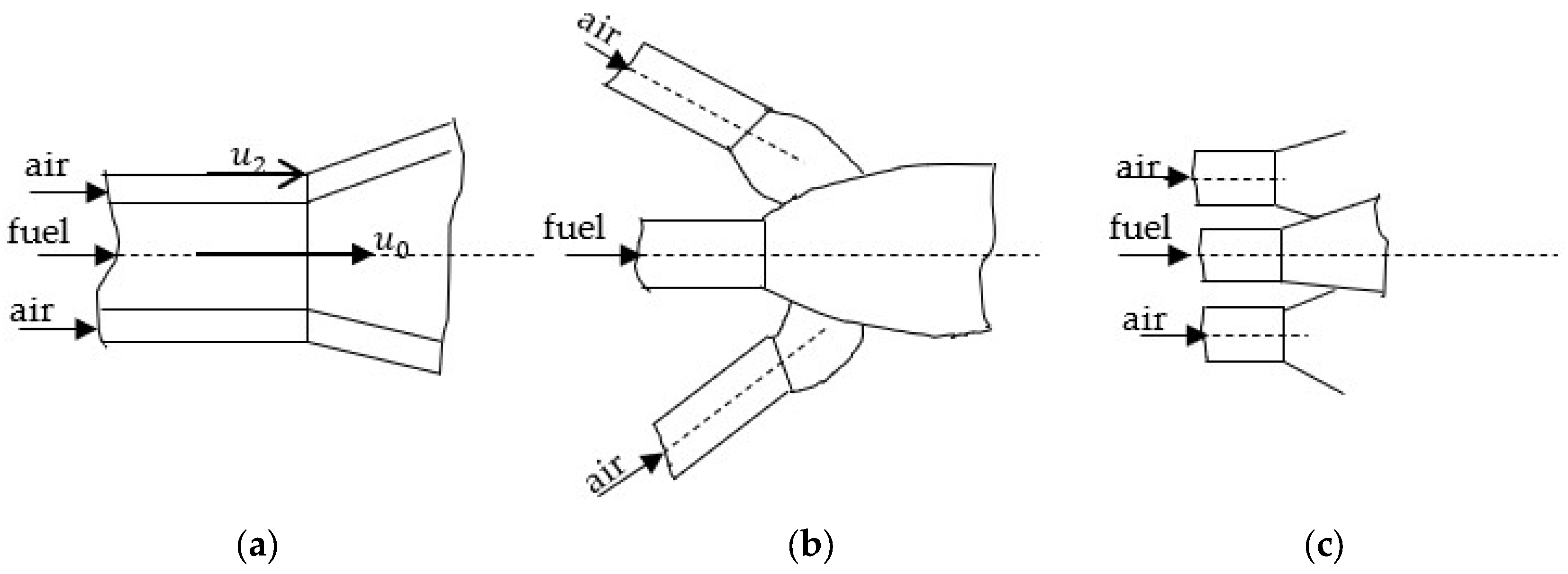
Oxidant admission can be configured through coaxial fuel–oxidant jets or by employing incident jets of fuel and oxidant. These diffusion combustion concepts are illustrated in
Figure 1 [
6,
7].
In diffusion combustion, the penetration of the oxidizing agent into the fuel jet is of paramount importance. Consequently, both the overall geometry of the burner and the velocity ratio (m) between the oxidizer and the fuel represent key parameters (with a superunitary ratio), defined as
, where
is the velocity of the gas at the nozzle exit and
is the velocity of the oxidizing air at its corresponding nozzle exit, as illustrated in
Figure 1. High velocities, required to establish the flame geometry, result in combustion processes occurring under turbulent flow conditions, where turbulence plays a crucial role in the overall combustion process.
The complex phenomena occurring within a flame include momentum transfer (governed by turbulent flow), mass transfer (which influences the variation in oxidizer concentration relative to that of the fuel, thereby affecting the combustion process as a whole), and heat transfer (through convection and radiation). An analogy exists among these transport processes in terms of their underlying physical mechanisms, which allows for their treatment in a similar manner. The potential (, or concentration difference, for a transported property (S) within the flame is defined by the relation , where is the fluid density. The following characteristic transport mechanisms can thus be distinguished:
where
m is the mass of the substance in kg;
v—flow velocity, m/s;
V—reference volume,
m3. For momentum, the transported quantity will be the velocity
where
is the specific heat of the gaseous medium, in
;
t—temperature of the gaseous medium. The use of a single symbol,
P, was intended to highlight the similarity of processes related to momentum transfer (
PI), mass transfer (
Pm), and heat transfer (
PQ).
Since
, temperature exerts a dual influence on heat transfer. For a fluid under turbulent flow conditions, all these functions exhibit random values in time, being expressed as the sum of a mean value,
, and a fluctuating component,
(pulsation), with the time-averaged fluctuation equal to zero.
The intensity of pulsations is defined by the relation:
The turbulence intensity, an essential parameter in characterizing turbulent flow, is defined for the three components of flow velocity by the relation:
The turbulence degree, a global parameter derived from turbulence intensity, typically assumes values of about 10% within a turbulent boundary layer and up to 80% at the edge of a jet.
Moreover, turbulence introduces, for each Navier–Stokes equation, three additional terms, which result in the formation of an extra tensor. This leads to an effective increase in the viscosity coefficients, represented by the turbulent viscosity term of the form . The turbulent viscosity coefficient, , is determined based on several hypotheses:
- -
Prandtl’s first hypothesis, which, for a free jet, introduces a linear dependence between the characteristic turbulent mixing length (corresponding to the jet’s characteristic transverse dimension) and the velocity variation between its maximum and minimum values;
- -
the Prandtl–Kolmogorov hypothesis, according to which turbulent viscosity depends on the turbulence intensity parameter K;
- -
the Spalding hypothesis (also known as the model K–W), where turbulent viscosity is defined as a function of both the turbulence intensity K and the mean pulsation frequency of velocity fluctuations W.
For turbulent flow, the condition of flame stability at the local microscopic scale is ensured when the axial flow velocity
equals the turbulent burning velocity
[
7,
8,
9].
A fundamental difference, however, exists between the laminar burning velocity
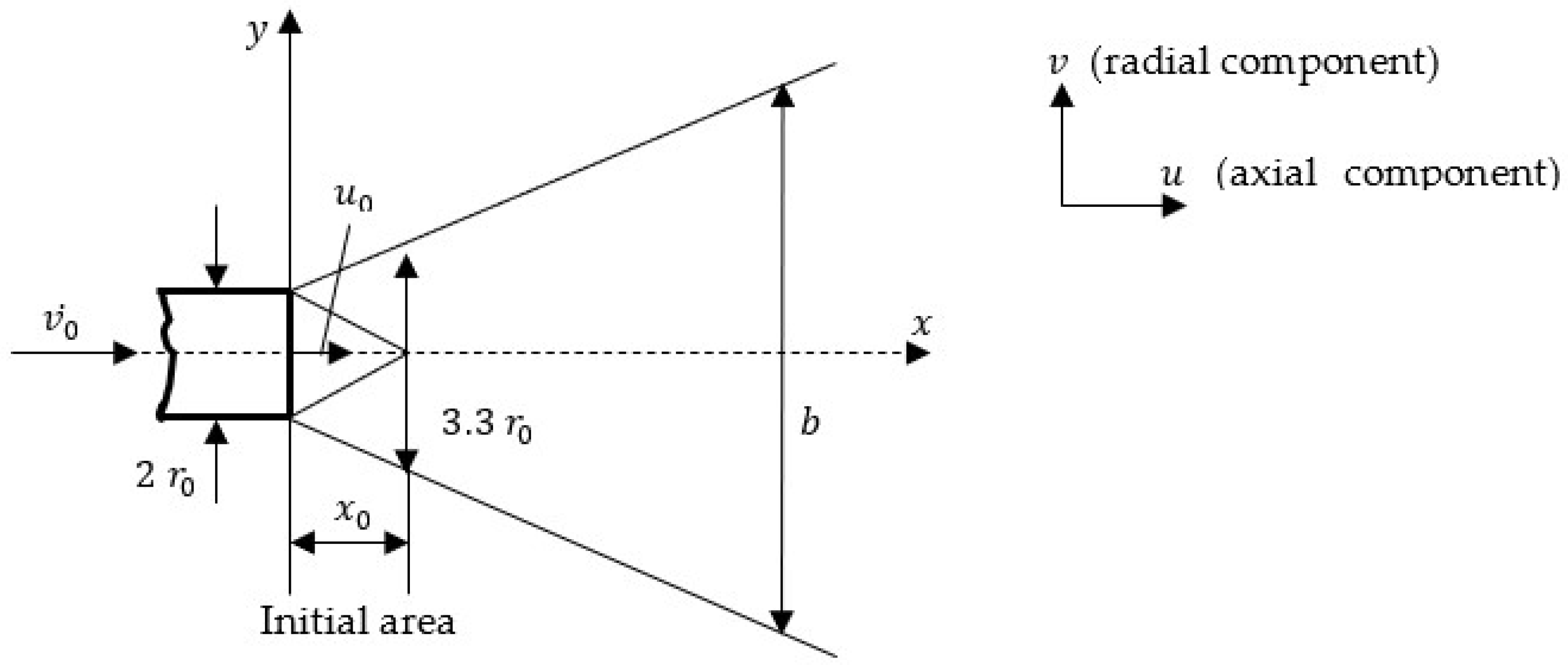
defined under standard conditions as a function of the gaseous fuel composition, and the turbulent burning velocity. In the case of gaseous fuel jet flames, the flow is generally within the high-turbulence regime, which also manifests in the shortening of the jet’s initial region, as illustrated in
Figure 2 [
7].
As a result of turbulence, in the case of a symmetric jet, the velocities
and
(with the transverse velocity considered negligible) consist of a temporally constant mean component
and a pulsating component
[
10].
Since pulsations consist of an alternation of positive and negative values, their time average is equal to zero.
The mixing length is defined as the distance that a particle must travel such that the difference between the instantaneous velocity
and the mean velocity
becomes equal to the axial pulsation
. Thus, the axial velocity pulsation
, which governs mass exchange, can be expressed as [
11,
12]:
Assuming that turbulence induces a relative equality between axial and transverse (radial) pulsations, the following relation for the transverse velocity pulsation
is obtained:
Finally, for the jet width
b, the resulting relations are obtained:
At the end of the initial region, the jet width reaches an approximate value of
(
Figure 1).
The volumetric flow rate of entrained air,
, up to a section
, can be determined using the relation [
7]:
where
represents the flow rate at the nozzle exit, expressed in
.
The maximum axial velocity
u along the jet axis can be calculated using the relation [
7]:
where
a is the jet structural coefficient. For a cylindrical nozzle,
a = 0.08, while for a round convergent nozzle,
.
The axial velocity at a point with coordinates (x,y) is given by:
In combustion stability, as expressed in relation (12), it is necessary to account for the hyperbolic decay of velocity along the jet axis with increasing distance, as well as for the parabolic decay of velocity with respect to the radial position [
12,
13,
14].
The design of burners, as well as the study of their functional behavior for relatively simple flow configurations, can be carried out using the calculation relations for isothermal jets. The innovative burner developed in this work, illustrated in
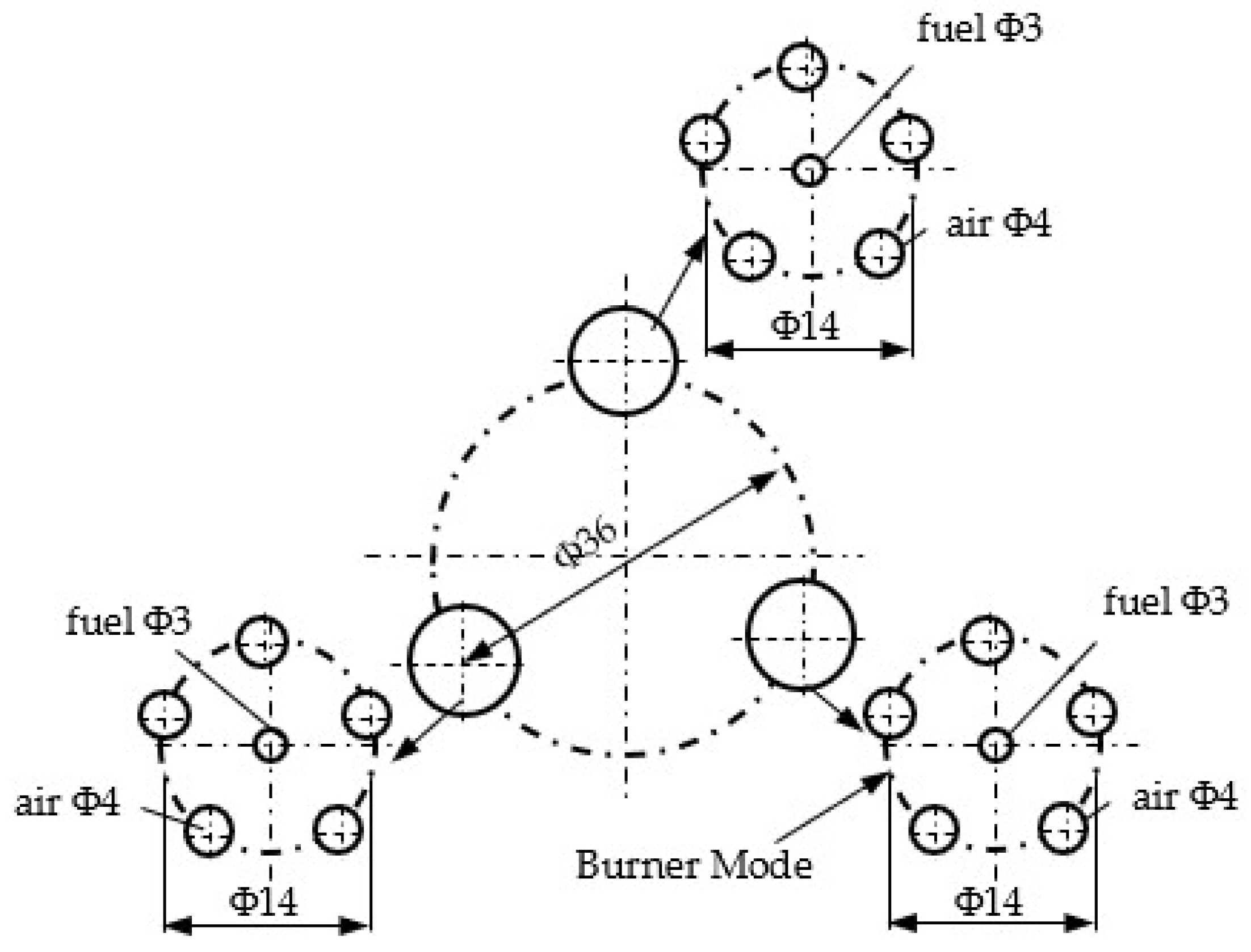
Figure 3, consists of three structural–functional modules, each module comprising one gas nozzle surrounded by five air intake nozzles. The burner operates under a diffusion combustion regime, in a structural–functional configuration with parallel jets, as previously shown in
Figure 1c. The sizing of the fuel nozzle was determined with an inner diameter of 3 mm, while the inner diameter of the air nozzles was set to 4 mm.
The aerodynamics of the gas–oxidizer interaction are illustrated in
Figure 4 by means of a planar projection, in which the fuel jet is intersected by two air jets. The intersection between the central fuel jet and the peripheral air jet is denoted by “a” [
6].
For the Cartesian coordinate system shown in
Figure 3, the intersection of an outer air jet with the fuel jet was calculated. The intersection point a was obtained by solving the system of equations corresponding to lines
and
.
The equations of the lines are expressed as follows:
where
representing the inclination angle of the jets
Thus, the solution of the system representing the intersection of lines
and
, which determines the position of point “a”, leads to the following relations:
The numerical calculations applied to the burner dimensions resulted in the following coordinates for the intersection point “a”. The calculations employed the following geometric parameters of the burner: , , , ; the results are: , .
It can be observed that the burner geometry allowed for fuel–air contact at a point located immediately downstream of the nozzle exits.
In the experiment, the burner was supplied with 1.2 Nm3/h of fuel gas, while the air, supplied from a compressor unit, was continuously regulated to maintain an excess air level of .
The ozone generator provided a flow rate of 60 mg/h, which, expressed in
volumetric equivalent, resulted in an equivalent oxygen concentration in the air used during the experiments of 21.7%. Consequently, the air had the following composition:
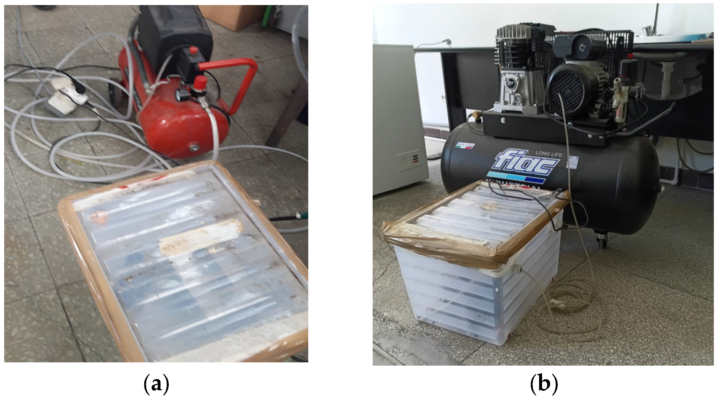
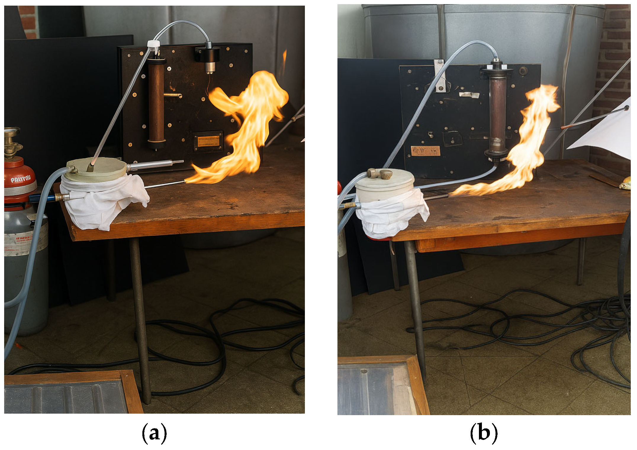
Figure 5a shows the oxidant supply system (air and ozone) for the experimental setup, which includes the pilot burner, an air compressor (Einhell TC–AC/190), the ozone generator, flow measurement system using rotameters, thermocouples (Φ6 × 500 mm), a gas analyzer (TESTO 350), and gas cylinders containing the hydrogen–methane mixture in the desired proportions with pressure-reduction systems.
The S-type thermocouples (PtRh10%-Pt(S), code TC–6) cover temperature measurements up to a maximum of 1400 °C. The rotameter for the fuel gas allows flow rates up to 2 m3/h, while the air rotameter allows flow rates up to 60 m3/h. The H2–CH4 gas mixture cylinders were supplied by Linde.
Figure 5b shows an overall view of the experimental setup. The experiments involved two fuel quantities, depending on the H
2/CH
4 mixture ratio, hereinafter denoted as:
- -
Fuel I (20% H2, 80% CH4);
- -
Fuel II (30% H2, 70% CH4)
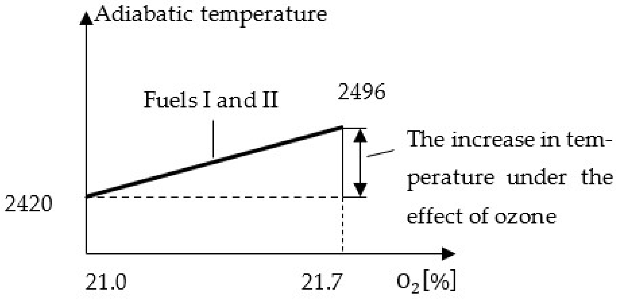
Calculations of the adiabatic temperature indicated an average increase of approximately 76 °C during the combustion of both gaseous fuels, corresponding to the rise in oxygen concentration in the air to 21.7%, as shown in
Figure 6.
The ozone produced by the generator was introduced into the air intake of the compressor fan.
3. Results
Figure 7 shows the flame characteristics for Fuel I, while
Figure 8 shows those for Fuel II, both compared with the flame of pure methane.
The experimental part of the study involved the combustion of CH4–H2 fuel mixtures, monitoring the thermodynamic parameters of the flame, and comparing them with the combustion of pure methane. The experimental investigations were conducted under the following conditions:
- -
Fuel flow rate: /h, using Fuel I, Fuel II, and pure natural gas;
- -
Air flow rate: determined according to the excess air condition λ = 1.05.
Experimental measurements included the determination of the following parameters:
- -
flame length;
- -
flame stability;
- -
flame temperatures at distances of 120 mm and 240 mm from the fuel nozzle exit;
- -
composition of combustion gases at the end of the flame.
Regarding flame stability, the test results were entirely positive: the flames formed immediately after the nozzle exit without pulsations or tendencies for local extinction (“blow-off”). The photographs of the flames also include details of the burner body. The images covered time sequences ranging from 1 to 20 s.
Figure 9 shows the flame length as a function of H
2 content. A slight decrease in flame length is observed with increasing H
2 proportion, due to the earlier ignition of hydrogen compared to methane and its higher burning velocity. The presence of H
2 in the fuel did not induce flame pulsations or preferential flow-direction tendencies leading to extinction.
The flame was developed in free air to eliminate the influence of a combustion chamber on flame characteristics, particularly since flame stability was the primary focus of the study.
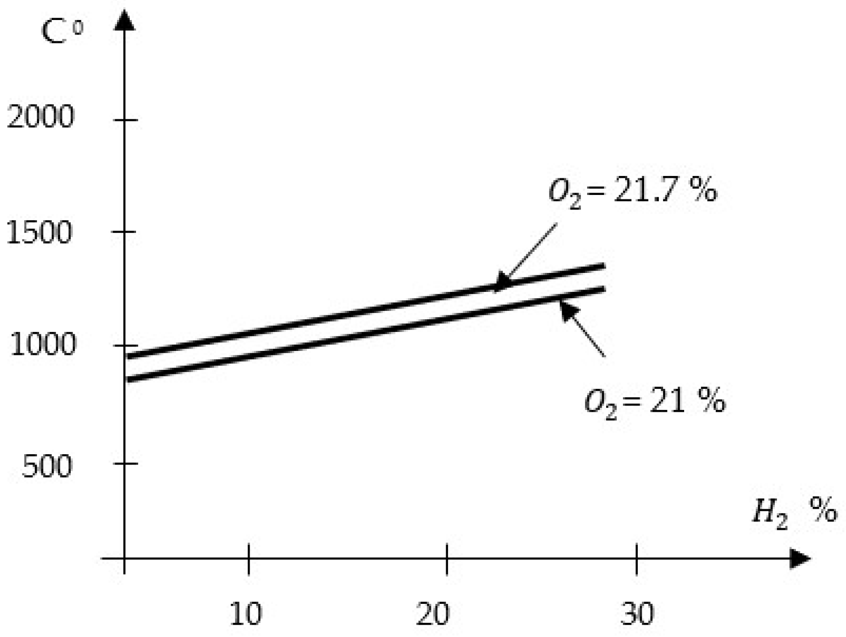
Figure 10 illustrates the thermal field within the flame at a position 120 mm downstream from the burner exit. The observed increase in temperature with the rising proportion of H
2 confirmed the hypothesis of the initial ignition of hydrogen, accompanied by a displacement of the flame core towards the burner outlet section.
This trend was maintained both for the oxidant with O
2 = 21% and for the oxygen-enriched oxidant (O
2 = 21.7%).
Figure 10 presents the results of flame temperature measurements at a specific point, with values differing from the adiabatic temperatures, which correspond to quantities calculated for the theoretical combustion regime.
No experimental tests were carried out at partial fuel flow rates, where an increase in the oxygen concentration in the oxidant could have been achieved, since the study focused exclusively on combustion with slightly oxygen-enriched air.
The data presented in
Figure 9 and
Figure 10 highlighted the influence of both the hydrogen concentration and the increased O
2 concentration in the oxidant, achieved through ozone injection, on the overall combustion process. The flue gas analysis at the flame exhaust indicated a reduction in pollutant emissions, as evidenced by the following average CO
2 values (based on a reference measurement condition at O
2 = 3%):
- -
Fuel: 100% CH4 → CO2 = 8.75%;
- -
Fuel: 20% H2 + 80% CH4 → CO2 = 7.97%;
- -
Fuel: 30% H2 + 70% CH4 → CO2 = 7.77%.
The flue gas analysis therefore indicated a decrease in CO
2 emissions, directly dependent on the hydrogen blending ratio [
15,
16,
17].
The tests constitute an initial qualitative experimental investigation of the problem, with particular emphasis on ignition, stable combustion, pulsations, and CO emissions. Process-related errors will be quantified in future experiments once the test facility is equipped with the required instrumentation. The results presented here were selected from a broad series of experiments that demonstrated consistent repeatability.
