Abstract
In sensorless control systems of permanent magnet synchronous motors (PMSMs), the traditional linear extended state observer (LESO) is preferred due to its simplicity and ease of implementation. With the development of PMSM sensorless control systems, the requirements for position estimation performance have increased, and thus, traditional LESOs can no longer meet those needs. To address this issue, this article proposes an estimation method based on an integrally compensated-enhanced linear extended state observer (IC-ELESO) and an improved quadrature phase locked loop (IQPLL) with a third-order LESO. In the back electromotive force estimation scheme, by introducing a compensation loop, the proposed IC-ELESO suppresses DC bias and improves position estimation accuracy compared to traditional LESOs. In the position estimation scheme, the IQPLL combines the third-order LESO with a quadrature phase locked loop (QPLL) to eliminate errors introduced by ramp signals. Finally, a PMSM experimental platform is built to conduct a comparative experiment between the method proposed and the traditional LESO, which verifies the feasibility and superiority of the method proposed in this article.
1. Introduction
Permanent magnet synchronous motors (PMSMs), which have high efficiency and power density, make them an ideal choice for drive systems [1,2,3]. The sensorless control of PMSMs offers competitive advantages in terms of improved reliability and reduced costs [4,5]. In recent years, sensorless control technology for PMSMs has been extensively researched. Generally, sensorless control can be categorized into model-based methods [6,7,8] and high-frequency injection methods [9,10].
Motor model-based strategies have attracted extensive interest owing to their inherent design flexibility and straightforward implementation. Various model-dependent approaches have been proposed in the literature, such as the model reference adaptive system (MRAS) [11,12], extended Kalman filter (EKF) [13], flux linkage observers [14,15], and back electromotive force (BEMF) estimation techniques [16,17]. Among them, BEMF estimation methods stand out due to their implementation simplicity and robust estimation performance. Typically, such schemes comprise a BEMF observer in conjunction with a rotor position estimation algorithm.
The realization of BEMF observer techniques can be further categorized into several forms, including the sliding mode observer (SMO) [18,19], Luenberger observer [20], and extended state observer (ESO) [21,22,23], among others. Active disturbance rejection control (ADRC) is less dependent on precise mathematical models and has stronger anti-interference capabilities. The ADRC consists of a tracking differentiator, ESO, and a nonlinear state error feedback controller. As the core of ADRC, ESO has a decisive influence on the system’s anti-interference performance. ESO can not only estimate the known state variables of the system, but also estimate the unknown disturbances of the system. Therefore, ESO is widely used in uncertain systems. ESO can be divided into linear ESO (LESO) and nonlinear ESO (NESO). NESO has high estimation accuracy and fast response speed, but due to the large number of setting parameters and complex stability analysis, its application in the engineering field is hindered. In contrast, LESO is easy to set parameters and easy to analyze stability, so it is often used in engineering practice.
As a position sensorless control technology, LESOs have been studied by many scholars in recent years. The traditional second-order LESO has a second-order low-pass filter characteristic, which also causes the introduction of DC bias and noise. Therefore, the improvement of traditional LESOs has become a significant research direction. In [21], the sinusoidal tracking unit with LESO was proposed to guarantee its BEMF tracking performance, which can obtain back EMF without phase lag. An adaptive bandwidth tuning scheme is proposed to tune online the parameters of the ESO, with which the desired estimation performance of BEMF can be achieved in a wide speed-operation range [22]. In [23], a LESO was proposed, which plants a reduced-order quasi-resonant controller into the internal model of a conventional LESO so that BEMFs without the phase lag are obtained. The DC offset position estimation error caused by the lagging phase of estimated BEMFs is eliminated by adopting the proposed scheme. In [24], the proposed backstepping extended state observer is obtained by inverse design according to the transfer function of the second-order bandpass filter. This enables the ESO to accurately estimate BEMFs while also being able to suppress DC bias.
The above method improves the performance of LESOs to a certain extent, but the structure of the improvement scheme is relatively complex. This article proposes a novel estimation scheme based on an integrally compensated-enhanced LESO (IC-ELESO). This method has a simple structure and easy parameter adjustment. It can suppress DC bias and improve position estimation. At the same time, combining a quadrature phase locked loop (QPLL) with the third-order LESO improves the QPLL, which replaces the proportional–integral (PI) controller. This scheme can eliminate the influence of the position ramp signal and improve the dynamic performance of the system.
The rest of this article is organized as follows: The mathematical model of PMSM, estimation scheme based on traditional LESO, and QPLL are given in Section 2. In Section 3, the design of IC-ELESO are presented. The design of the IQPLL method is given in Section 4. Section 5 shows the experimental results. Finally, conclusions are drawn in Section 6.
2. Sensorless Control Method Based on Second-Order LESO and QPLL
2.1. Mathematical Model of PMSM
The research object of this article is the surface-mounted permanent magnet synchronous motor (SPMSM). Assuming that the air gap magnetic field is sinusoidal, and the magnetic circuit is not saturated, the mathematical model of an SPMSM in the - stationary reference frame, which can be expressed in the following form:
where and are the -axis stator voltages; and are the -axis stator currents; is the stator resistance; are stator inductances; and p is the differential operator. and are the back electromotive force, satisfying
where is the permanent magnet flux; is the electrical angular velocity, and is the rotor position angle.
The electromagnetic torque of SPMSM in the rotating reference frame can be expressed as
where and are the electromagnetic torque and pole pair number, respectively, and is the q axis component of the stator current.
The motion equation of SPMSM is established as
where is the load torque of the motor; J is the moment of inertia of the motor; and B is the viscous damping of the motor.
2.2. BEMF Estimation Scheme Based on the 2nd-LESO
Considering that the last item on the right side in (5) is regarded as a disturbance, the 2nd-LESO is designed as
where is the -axis estimated current, is estimated current error, and and are the gain coefficients of LESO.
When the system enters a steady state, the estimated value of the BEMF can be described as
In LESO, and are constants. From (9), it is obvious that the characteristic equation of the transfer function has two roots. For the convenience of analysis, these two roots are usually set at the same point in the left half plane of the real axis to ensure their stability. Therefore, and can be configured as
where is the bandwidth of the observer.
2.3. Position Estimation Scheme Based on the QPLL
The EMF is normalized and then input into the quadrature phase locked loop. The block diagram of the QPLL is shown in Figure 1.

Figure 1.
Block diagram of the QPLL.
The normalization is used to mitigate the effects of the BEMF amplitude variations, which are described as
The estimated BEMF with an amplitude normalization can be expressed as
The estimated position is considered to closely approach the actual position, and the position estimation error can be obtained as
Based on the above derivation, the structural block diagram of Figure 1 can be simplified as shown in Figure 2 below.
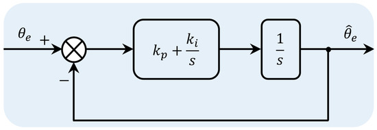
Figure 2.
Simplified block diagram of the QPLL.
The transfer function of the above figure can be written as
where and are the proportional and integral gains of the PI regulator in Figure 2, respectively.
Further, the error transfer function of QPLL is
It has been noted that when the input exhibits a ramp variation in frequency, the QPLL is prone to producing estimation deviations [25]. Based on the terminal value theorem, one can further deduce
where A represents the amplitude of the ramp frequency signal.
There are two problems with the above method:
- LESO has a second-order low-pass filtering characteristic. According to the amplitude–frequency characteristic, LESO cannot suppress the DC bias when estimating the back electromotive force, and the DC bias will cause position estimation errors.
- In the QPLL scheme, the accuracy of position estimation is easily affected by a ramp frequency signal. In addition, a major concern of the QPLL scheme lies in its poor anti-disturbance capability. For this purpose, low-pass filters (LPFs) are often introduced.
3. Proposed BEMF Estimation Scheme Based on the IC-ELESO
From (7), we can see that the disturbance observation value is the integral of error , which results in a slow tracking speed of the ESO for the disturbance and limited observation capability.
In order to solve this problem, a proportional link of the observation error is introduced in the disturbance observation to improve the observation efficiency of the disturbance. The structural diagram for this is shown in Figure 3. After adding the proportional link, the enhanced LESO (ELESO) is designed as
where is the differential gain coefficient of the observation error .
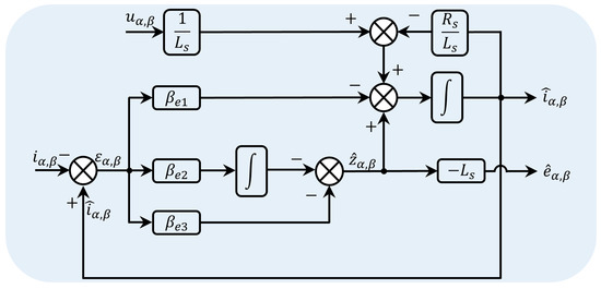
Figure 3.
Block diagram of the ELESO.
Similarly, the poles of the transfer function are usually set at the same point in the left half plane of the real axis to ensure its stability. , , and can be designed as
In order to suppress the DC bias during back electromotive force observation, the observer is combined with integral compensation. The structural block diagram is shown in Figure 4. The IC-ELESO scheme is designed as
where , and k are the estimated current of the compensation loop, the estimated current error of the compensation loop, and the compensation gain. is the estimated variable obtained by IC-ELESO.
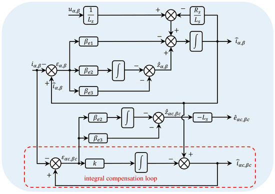
Figure 4.
Block diagram of the IC-ELESO.
When the system enters steady state, the estimated BEMF can be described as
The additional integral compensation loop reconstructs the disturbance observation channel by feeding back the estimation error. This ensures that DC errors are eliminated, and ensures the improvement of observation accuracy.
We then analyzed its amplitude-phase characteristics and constructed the Bode diagram, as shown in Figure 5. In the figure, of LESO and ELESO is set to 1000 rad/s, of IC-ELESO is set to 1000 rad/s, and k is set to 10. It can be seen that compared with LESO and ELESO, IC-ELESO can eliminate DC error and improve position estimation accuracy. In addition, IC-ELESO has a simple structure and easy parameter tuning.
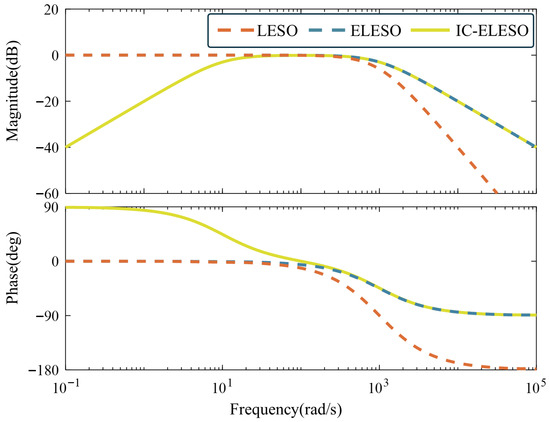
Figure 5.
Bode plots of different BEMF estimation schemes.
4. Position Estimation Scheme Based on the IQPLL with Third-Order LESO
This section will perform position estimation based on the IQPLL with a third-order LESO. Block diagram of the position estimation scheme based on IQPLL with a third-order LESO is presented in Figure 6.
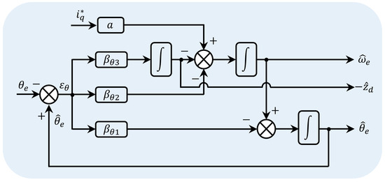
Figure 6.
Block diagram of the IQPLL.
Considering the influence of parameter changes, (4) can be rewritten as
where , , , , , and are the disturbances caused by parameter changes.
And, it can be given by
Based on (27), the third-order LESO can be obtained to perform position estimation
where , , and are the gain coefficients of the third-order LESO.
According to (29), after deriving the characteristic equation of the IQPLL, the three poles are deliberately assigned to the same point in the left half plane of the real axis to simplify the parameter tuning process, as shown below.
Therefore, the gain coefficient of the third-order LESO is
where is the bandwidth of the position observer.
From (29), the position estimation error transfer function can be derived as
For a ramp-shaped frequency input, the final value theorem can be used to derive the resulting estimation error in the IQPLL.
Therefore, when the position changes rapidly, IQPLL with the third-order LESO can estimate the position more accurately.
5. Experimental Results
In order to further verify the feasibility and effectiveness of the control method proposed in this paper, an SPMSM experimental platform was built, as shown in Figure 7. The specific parameters of the SPMSM used are shown in Table 1. A dSPACE DS1202 real-time control system with a sampling frequency of 20 kHz is utilized as a controller. An SiC MOSFET-based inverter is utilized as a driver. The dead-time of the inverter is set to 3.12 μs. The speed-loop sampling frequency is 2 kHz.
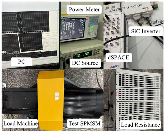
Figure 7.
Experimental platform of SPMSM control system.

Table 1.
Parameters of the test SPMSM.
The structural block diagram of the sensorless control method proposed is shown in Figure 8. In the experimental section, comparative experiments were conducted on LESO, ELESO, and IC-ELESO, verifying the superior performance of IC-ELESO under steady state, dynamic state, variable load, and DC bias conditions. Furthermore, the position estimation accuracy of QPLL and IQPLL was compared, demonstrating that IQPLL estimates positions more accurately. It also verifies that the proposed IC-ELESO exhibits robustness under varying motor parameters. In the analysis of the estimation accuracy of the observer position, position estimation accuracy is quantified by the maximum absolute error between the actual position and the estimated position. The improvement in positional accuracy is quantified as the reduction in positional estimation error achieved by the proposed method compared to traditional methods.
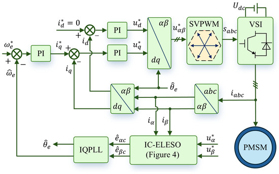
Figure 8.
The structural block diagram of the sensorless control method proposed.
5.1. Performance Comparison Experiment of QPLL and IQPLL
Figure 9 shows the experimental waveform of the motor under a load of 0.5 N·m, with the speed ranging from 600 to 800 to 1000 rpm. Figure 9a shows the experimental waveform of QPLL, and Figure 9b shows the experimental waveform of IQPLL. In both QPLL and IQPLL, BEMF is obtained using the LESO approach. In Figure 9, as the motor speed increases, the position estimation accuracy decreases, which verifies the low-pass filtering characteristics of LESO. The higher the motor speed, the more obvious the phase delay, and the position estimation accuracy is reduced. It can be seen that during the motor acceleration process, the maximum position estimation error obtained by QPLL is 0.32 rad, and the maximum position estimation error obtained by IQPLL is 0.24 rad. Under rapid changes in motor speed, the position estimation error of IQPLL is reduced by 25% compared with QPLL. Therefore, under both steady-state operation and speed acceleration, the IQPLL position estimation method proposed in this article demonstrates superior performance and provides higher estimation accuracy.
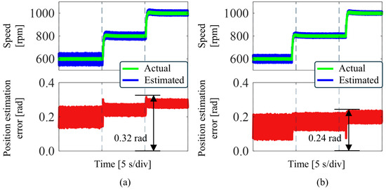
Figure 9.
Experimental waveforms of different PLLs under speed changes. (a) LESO+QPLL. (b) LESO+IQPLL.
5.2. Performance Comparison Experiment of Different BEMF Estimation Schemes
Figure 10 shows the experimental waveform of three schemes under the motor speed changing from 800 to 1000 rpm, and the load is 0.5 N·m. The position estimation method used by the three BEMF observation schemes is IQPLL. Figure 10a shows the experimental waveforms of the LESO. It shows that the LESO position estimation error is 0.24 rad at a motor speed of 1000 rpm. Figure 10b shows the experimental waveforms of the ELESO. It shows that the ELESO position estimation error is 0.15 rad at a motor speed of 1000 rpm. Figure 10c shows the experimental waveforms of the proposed IC-ELESO. It shows that the position estimation error is 0.07 rad at a motor speed of 1000 rpm. The proposed IC-ELESO reduces position estimation error by 70.8% compared to the traditional LESO under conditions of varying motor speed and by 53.3% compared to the ELESO under conditions of varying motor speed. Compared with LESO and ELESO, the IC-ELESO position estimation error proposed is relatively small. The high position accuracy of IC-ELESO has been verified.
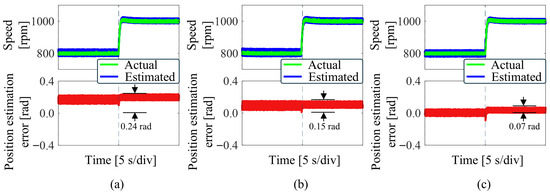
Figure 10.
Experimental waveforms of different BEMF estimation schemes under speed changes. (a) LESO+IQPLL. (b) ELESO+IQPLL. (c) IC-ELESO+IQPLL.
Figure 11 shows the experimental results of three methods when the load changes from 0.5 N·m to 3 N·m, and then to 0.5 N·m. The motor speed is 1000 rpm. Figure 11a–c show the experimental waveforms of LESO, ELESO, and IC-ELESO, respectively. It can be seen from the figure that when the load changes, the maximum error of LESO position estimation is 0.27 rad, the maximum error of ELESO position estimation is 0.15 rad, and the maximum error of the proposed IC-ELESO is reduced to 0.11 rad. Under load changes, the proposed IC-ELESO reduces position estimation error by 59.3% compared to the traditional LESO and by 26.7% compared to the ELESO.
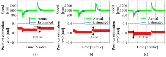
Figure 11.
Experimental waveforms of different BEMF estimation schemes under load changes. (a) LESO+IQPLL. (b) ELESO+IQPLL. (c) IC-ELESO+IQPLL.
In order to verify the ability of the proposed method to suppress DC bias, a comparative experiment of three BEMF observation schemes under DC bias was carried out. The experimental results are shown in Figure 12. Under steady state operation, 2 A DC error is added to the observer input current. Figure 12a,b show that under DC bias, the speed observation values of LESO and ELESO exhibit significant fluctuations, and the position observation error increases. Figure 12c shows that the speed observation value of IC-ELESO exhibits only brief jitter, and the position observation error remains essentially unchanged. Therefore, compared with the previous two methods, the proposed IC-ELESO can suppress DC bias.
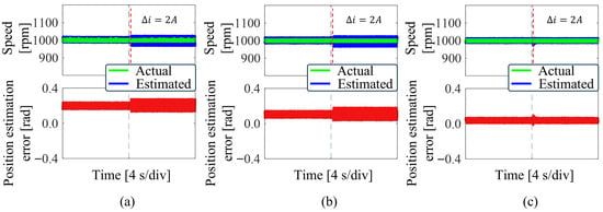
Figure 12.
Experimental waveforms of different BEMF estimation schemes under DC bias. (a) LESO+IQPLL. (b) ELESO+IQPLL. (c) IC-ELESO+IQPLL.
5.3. Robustness Analysis of IC-ELESO Under Motor Parameter Variations
Figure 13 shows the experimental waveforms of the proposed method under varying motor parameters, with the motor speed set at 1000 rpm. Figure 13a indicates that under resistance variations, the motor speed remains essentially unchanged, and the position estimation error stays constant. Figure 13b demonstrates that under inductance variations, the motor speed fluctuates briefly before stabilizing, while the position estimation error remains largely unchanged. It can be concluded that the proposed method exhibits robustness under varying motor parameters.
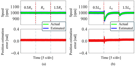
Figure 13.
Experimental waveforms of IC-ELESO+IQPLL under motor parameter variations. (a) Resistance change. (b) Inductance change.
6. Conclusions
In this article, a position sensorless control method of SPMSM drives based on IC-ELESO and IQPLL was proposed. Compared with the traditional LESO for observing BEMF, IC-ELESO is based on an improved BEMF estimation model and can quickly estimate the BEMF. IC-ELESO can suppress DC bias and improve estimation accuracy. At the same time, parameter tuning is simple. Combining the conventional QPLL with the third-order LESO improves position estimation performance. Under rapid changes in motor speed, the position estimation accuracy of IQPLL is higher than that of QPLL. Finally, the feasibility and effectiveness of the proposed scheme are verified on the SPMSM experimental platform. The proposed IC-ELESO reduces position estimation error by 70.8% compared to the traditional LESO under conditions of varying motor speed and by 53.3% compared to the ELESO under conditions of varying motor speed. Under conditions of varying motor load torque, the proposed IC-ELESO reduces position estimation error by 59.3% compared to the traditional LESO and by 26.7% compared to the ELESO. Under rapid changes in motor speed, the position estimation error of IQPLL is reduced by 25% compared with QPLL.
Author Contributions
Conceptualization, J.L. and M.D. (Manfeng Dou); Data curation, D.Z. and Z.H.; Funding acquisition, D.Z. and Z.H.; Investigation, J.L. and H.J.; Methodology, J.L.; Resources, M.D. (Manfeng Dou) and Z.H.; Software, J.L. and M.D. (Mengxi Dang); Supervision, D.Z. and Z.H.; Validation, H.J., S.Y. and M.D. (Mengxi Dang); Visualization, S.Y., M.D. (Mengxi Dang) and D.Z.; Writing—original draft, J.L.; Writing—review and editing, J.L. and Z.H. All authors have read and agreed to the published version of the manuscript.
Funding
This work was supported by the Key Research and Development Program of Shaanxi Province (No. 2024GX-YBXM-266, No. 2024GX-YBXM-457) and the Fundamental Research Funds for the Central Universities.
Institutional Review Board Statement
Not applicable.
Informed Consent Statement
Not applicable.
Data Availability Statement
The original contributions presented in this study are included in the article. Further inquiries can be directed to the corresponding author.
Conflicts of Interest
The authors declare no conflicts of interest.
References
- Liu, L.; Wang, K.; Guo, L.L.; Li, J. Analysis of Inter-Turn Short Circuit Faults in Dual Three-Phase PMSM for Electromechanical Actuator. IEEE Trans. Transp. Electrif. 2023, 9, 4059–4070. [Google Scholar] [CrossRef]
- Kandil, A. Investigation of the whirling motion and rub/impact occurrence in a 16-pole rotor active magnetic bearings system with constant stiffness. Nonlinear Dyn. 2020, 102, 2247–2265. [Google Scholar] [CrossRef]
- Li, J.; Wu, X.; Wu, L. A Computationally-Efficient Analytical Model for SPM Machines Considering PM Shaping and Property Distribution. IEEE Trans. Energy Convers. 2024, 39, 1034–1046. [Google Scholar] [CrossRef]
- Yan, H.; Wang, W.; Xu, Y.; Zou, J. Position Sensorless Control for PMSM Drives With Single Current Sensor. IEEE Trans. Ind. Electron. 2023, 70, 178–188. [Google Scholar] [CrossRef]
- Xu, G.; Xiao, F.; Lian, C. A Position Sensorless Control Strategy for PMSM Drives With Single-Phase Current Sensor. IEEE Trans. Transp. Electrif. 2024, 10, 4678–4688. [Google Scholar] [CrossRef]
- Zhao, Y.; Zhang, Z.; Qiao, W.; Wu, L. An Extended Flux Model-Based Rotor Position Estimator for Sensorless Control of Salient-Pole Permanent-Magnet Synchronous Machines. IEEE Trans. Power Electron. 2015, 30, 4412–4422. [Google Scholar] [CrossRef]
- Liu, S.; Liu, L.; Lin, Q.; Jin, D.; Liang, D. A High Order Nonlinear Adaptive Observer for PMSM Speed-Flux Transformation Model: A PMSM Sensorless Control Scheme. IEEE Trans. Power Electron. 2025, 40, 10889–10898. [Google Scholar] [CrossRef]
- Zhan, H.; Zhu, Z.Q.; Odavic, M.; Li, Y. A Novel Zero-Sequence Model-Based Sensorless Method for Open-Winding PMSM With Common DC Bus. IEEE Trans. Ind. Electron. 2016, 63, 6777–6789. [Google Scholar] [CrossRef]
- Li, H.; Zhang, X.; Yang, S.; Liu, S. Unified Graphical Model of High-Frequency Signal Injection Methods for PMSM Sensorless Control. IEEE Trans. Ind. Electron. 2020, 67, 4411–4421. [Google Scholar] [CrossRef]
- Bi, G.; Zhang, G.; Wang, Q.; Ding, D.; Li, B.; Wang, G.; Xu, D. High-Frequency Injection Angle Self-Adjustment Based Online Position Error Suppression Method for Sensorless PMSM Drives. IEEE Trans. Power Electron. 2023, 38, 1412–1417. [Google Scholar] [CrossRef]
- Liu, Z.-H.; Nie, J.; Wei, H.-L.; Chen, L.; Li, X.-H.; Lv, M.-Y. Switched PI Control Based MRAS for Sensorless Control of PMSM Drives Using Fuzzy-Logic-Controller. IEEE Trans. Power Electron. 2022, 3, 368–381. [Google Scholar] [CrossRef]
- Jiang, N.; Cao, R.; Sun, W.; Chen, D.; Wang, K. MRAS-Based Sensorless Control of PMSM Drives Using Extended State Observer in Shaftless Rim-Driven Thruster System. IEEE Trans. Transp. Electrif. 2025, 11, 6038–6047. [Google Scholar] [CrossRef]
- Xu, R.; Shen, X.; Lin, X.; Liu, Z.; Xu, D.; Liu, J. Robust Model Predictive Control of Position Sensorless-Driven IPMSM Based on Cascaded EKF-LESO. IEEE Trans. Transp. Electrif. 2025, 11, 8824–8832. [Google Scholar] [CrossRef]
- Xu, W.; Jiang, Y.; Mu, C.; Blaabjerg, F. Improved Nonlinear Flux Observer-Based Second-Order SOIFO for PMSM Sensorless Control. IEEE Trans. Power Electron. 2019, 34, 565–579. [Google Scholar] [CrossRef]
- Liu, J.; Zhang, Y. Performance Improvement of Nonlinear Flux Observer for Sensorless Control of PMSM. IEEE Trans. Ind. Electron. 2023, 70, 12014–12023. [Google Scholar] [CrossRef]
- Du, P.; Wang, B.; Xu, D. A Minimum-Order BEMF Observer for DC-Bias Elimination of Position-Sensorless PMSM Drives Using Backstepping Design. IEEE Trans. Ind. Electron. 2024, 71, 13635–13649. [Google Scholar] [CrossRef]
- Wang, G.; Wang, D.; Lin, H.; Wang, J.; Yi, X. A DC Error Suppression Adaptive Second-Order Backstepping Observer for Sensorless Control of PMSM. IEEE Trans. Power Electron. 2024, 39, 6664–6676. [Google Scholar] [CrossRef]
- Zhu, X.; Huang, J.; Wang, P.; Li, Y.; Qi, G.; Wu, Y.; He, Y.; Zhang, Y. An Improved Sliding Model Observer Sensorless Control for PMSM Based on Fuzzy Logic Controller and DSOGI-FLL. IEEE Trans. Transp. Electrif. 2025, 11, 823–834. [Google Scholar] [CrossRef]
- Cheng, Z.; Li, L.; Liu, X.; Bai, X.; Liu, J. Sensorless Control Based on Discrete Fractional-Order Terminal Sliding Mode Observer for High-Speed PMSM With LCL Filter. IEEE Trans. Power Electron. 2025, 40, 1654–1668. [Google Scholar] [CrossRef]
- Andersson, A.; Thiringer, T. Motion Sensorless IPMSM Control Using Linear Moving Horizon Estimation with Luenberger Observer State Feedback. IEEE Trans. Transp. Electrif. 2018, 4, 464–473. [Google Scholar] [CrossRef]
- Xia, Z.; Yu, X.; Wu, X.; Dou, Y. An Enhanced Linear Extended State Observer-Based Sensorless IPMSM Drives with Robustness Against Current Measurement Offset Error. IEEE Trans. Transp. Electrif. 2025, 11, 3558–3567. [Google Scholar] [CrossRef]
- Jiang, F.; Sun, S.; Liu, A.; Xu, Y.; Li, Z.; Liu, X.; Yang, K. Robustness Improvement of Model-Based Sensorless SPMSM Drivers Based on an Adaptive Extended State Observer and an Enhanced Quadrature PLL. IEEE Trans. Power Electron. 2021, 36, 4802–4814. [Google Scholar] [CrossRef]
- Chen, S.; Ding, W.; Hu, R.; Wu, X.; Shi, S. Sensorless Control of PMSM Drives Using Reduced Order Quasi Resonant-Based ESO and Newton–Raphson Method-Based PLL. IEEE Trans. Power Electron. 2023, 38, 229–244. [Google Scholar] [CrossRef]
- Li, Y.; Yin, Z.; Yuan, D.; Zhang, Y.; Gao, Y.; Yang, H. A Multiharmonics Suppression Backstepping Extended State Observer for the PMSM Electrolytic Capacitorless Drives Sensorless Control. IEEE Trans. Power Electron. 2025, 40, 10769–10782. [Google Scholar] [CrossRef]
- Wang, H.; Yang, Y.; Ge, X.; Zuo, Y.; Yue, Y.; Li, S. PLL- and FLL-Based Speed Estimation Schemes for Speed-Sensorless Control of Induction Motor Drives: Review and New Attempts. IEEE Trans. Power Electron. 2022, 37, 3334–3356. [Google Scholar] [CrossRef]
Disclaimer/Publisher’s Note: The statements, opinions and data contained in all publications are solely those of the individual author(s) and contributor(s) and not of MDPI and/or the editor(s). MDPI and/or the editor(s) disclaim responsibility for any injury to people or property resulting from any ideas, methods, instructions or products referred to in the content. |
© 2025 by the authors. Licensee MDPI, Basel, Switzerland. This article is an open access article distributed under the terms and conditions of the Creative Commons Attribution (CC BY) license (https://creativecommons.org/licenses/by/4.0/).