1. Introduction
The widespread deployment of inverter-interfaced distributed generation (DG) in microgrids has brought increased flexibility and resilience to modern power systems. However, ensuring stable operation, accurate power sharing, and fast dynamic response remains a critical challenge, especially under islanded or weak-grid conditions. Among the various control strategies, droop control has gained wide acceptance due to its simplicity and decentralized nature [
1,
2,
3,
4,
5]. This technique emulates the behavior of synchronous generators, enabling proportional load sharing without requiring communication links.
Despite its practicality, traditional droop control suffers from limitations such as steady-state errors, poor dynamic performance, and sensitivity to network impedance mismatches [
2,
3,
4,
5]. To overcome these issues, several enhanced droop-based techniques have been proposed. These include complex-impedance-aware designs [
2], small signal modeling and linearized state-space analysis [
3], output impedance shaping [
4], voltage-frequency droop control for improved transient response [
5], and decentralized virtual impedance [
6]. Additionally, robust formulations such as multivariable control [
7], dynamic angle oscillation suppression [
8], and adaptive droop controller [
9] have advanced the reliability of droop-controlled inverters.
A significant breakthrough in droop control came with the development of the UDC framework [
10,
11,
12,
13,
14]. Unlike conventional droop designs that rely on fixed impedance assumptions, the universal droop controller enables consistent power sharing among inverters with different output impedance types. This universal formulation has been further extended to handle abnormal conditions through a generalized droop control framework based on power flow equations and impedance-invariant control laws [
10], optimization-based parameter tuning [
11], PLL-free self-synchronized universal droop controller [
12], bounded droop control [
13], and seamless mode transitions [
14]. These enhancements improve the resilience and flexibility of inverter-fed microgrids. Capturing the internal behavior of DG sources (e.g., current controllers, voltage regulators) within the control structure can enhance predictive accuracy and improve control performance under variable operating conditions.
However, droop control, including UDC, inherently depends on quasi-steady-state approximations, which limit its effectiveness under fast transients and highly dynamic load or source conditions. To address this, Model Predictive Control (MPC) has emerged as a powerful alternative. MPC anticipates future system behavior using a model and computes optimal control actions in real time. In particular, FCS-MPC has shown promise for power electronic systems due to its compatibility with discrete-time inverter operations [
15,
16,
17,
18,
19,
20,
21].
Recent studies and future directions are discussed in [
15,
16] and MPC has been applied to improve frequency control [
17], implement master–slave microgrid coordination [
18], and introduce hierarchical droop-based predictive control schemes [
19]. Moreover, predictive approaches have been shown to be effective in mitigating low-frequency oscillations [
20] and enabling decentralized control in PV-based systems [
21]. In [
22] a droop-based FCS-MPC with a decentralized inner loop for parallel inverter resources was proposed to improve voltage tracking and frequency regulation but source dynamics were neglected. Poonahela et al. [
23] proposed a predictive voltage and frequency restoration scheme for decentralized FCS-MPC-based droop-controlled DGs in AC microgrids. In [
24], a FCS-MPC integrated with a universal droop controller was proposed for improving load power sharing in inverter-fed microgrids. Although the method showed superior performance compared to conventional droop-based approaches, the study neglected the source dynamics. This simplification reduces the system complexity but introduces several limitations: (i) The predictive model does not fully capture the actual behavior of the distributed generators (DGs), since the dynamic response of the sources such as DC-link variations and renewable intermittency are excluded. (ii) The results may be optimistic in simulation, but in practical scenarios, frequency and voltage stability could be adversely affected when source dynamics interact with inverter and line dynamics. Relevant studies with source dynamics are discussed in [
25,
26].
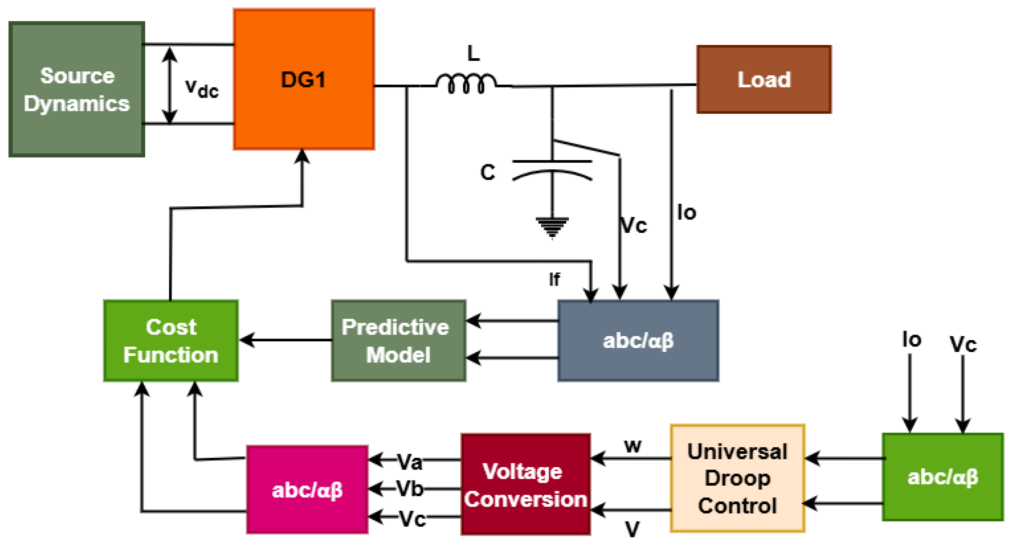
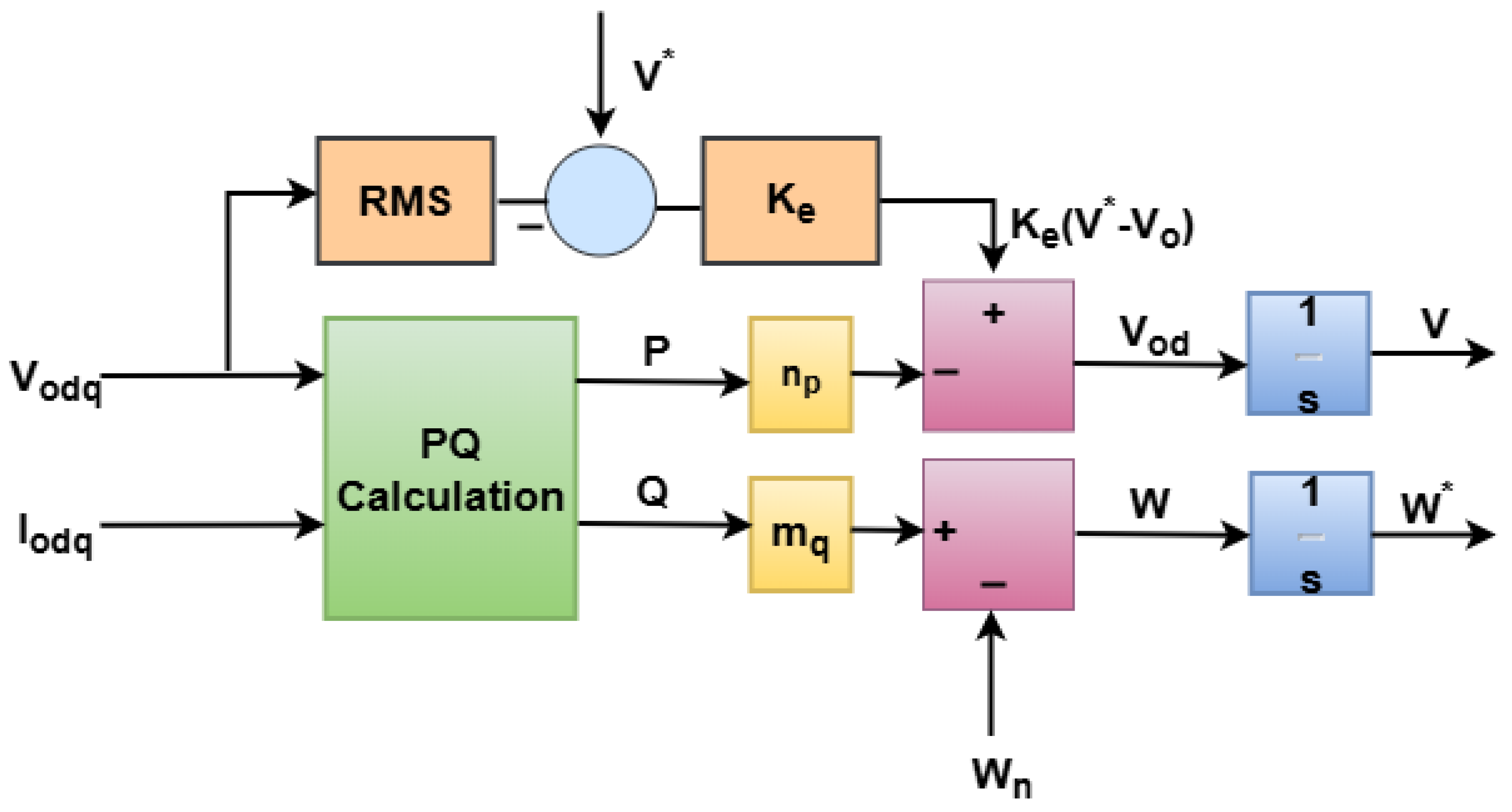
Based on the reviewed literature, previous works have primarily focused on the conventional droop controller, universal droop controller, and their combination with FCS-MPC. To the best of the authors’ knowledge, no prior studies have explored the control of parallel inverters using a universal droop controller integrated with FCS-MPC. In this approach, the frequency and voltage generated by the universal droop controller are converted into voltage references for FCS-MPC, which are then utilized in its cost function. This paper introduces an FCS-MPC scheme with universal droop control to enhance power sharing performance under impedance mismatches and load disturbances in the considered microgrid system.
In this context, this paper proposes a hybrid control strategy that combines UDC with an FCS-MPC, incorporating detailed source dynamics. The proposed approach ensures accurate steady-state power sharing while enhancing transient performance and robustness. The predictive controller minimizes a cost function based on voltage, frequency, and power errors, while UDC ensures coordination among inverters of varying characteristics. The main contributions of this work are as follows:
A novel hybrid FCS–MPC with a universal droop controller is proposed, incorporating both inverter and source dynamics to achieve accurate power sharing, fast transient response, and effective frequency/voltage regulation under varying load scenarios and different line impedances.
The effectiveness of the proposed approach is demonstrated through comparative analysis with a conventional PI controller. The proposed method shows improved power sharing accuracy in inverter-fed microgrids.
Validation of the proposed approach through real-time simulation.
The remainder of the paper is structured as follows:
Section 2 presents the system modeling of the inverter and source components.
Section 3 discusses the modeling of conventional droop controller.
Section 4 outlines the design and implementation of the proposed FCS-MPC algorithm, including the formulation of the cost function and universal droop control optimization strategy.
Section 5 discusses simulation results, including steady-state and transient performance comparisons with conventional controllers, and
Section 6 presents the discussion. Finally,
Section 7 concludes the paper and provides future research directions, including real-time hardware implementation using OPAL-RT OP4510 platforms.
5. Results and Discussions
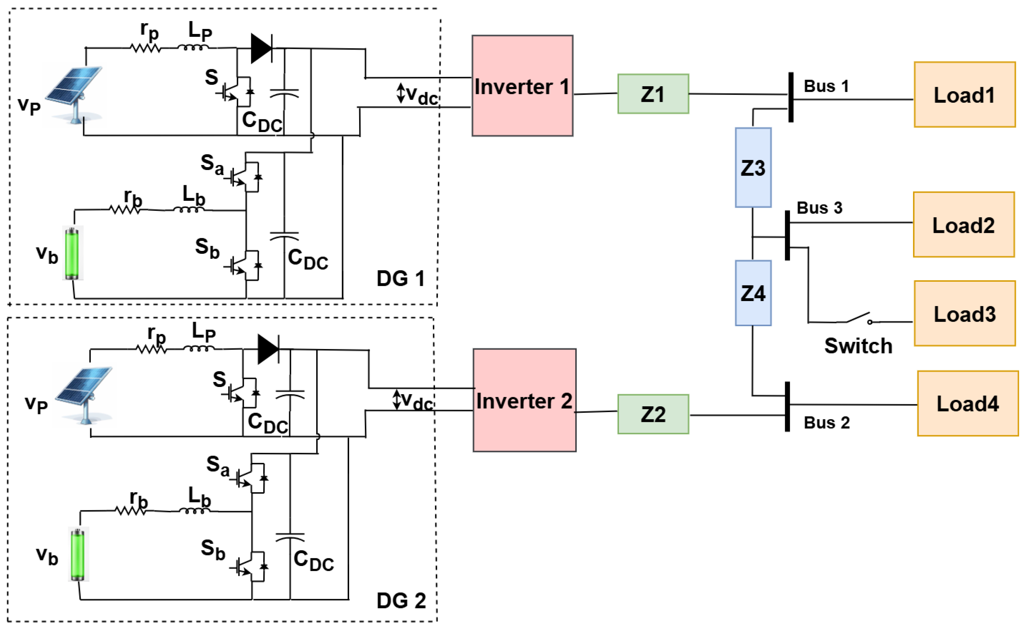
In this section, the proposed control model is simulated on the test system illustrated in
Figure 1. Loads 1, 2, and 4 are standard connected loads, while Load 3 is introduced as a disturbance load to assess the dynamic performance of the proposed controller in terms of power sharing and dynamic response of the system. The system is tested under unequal output line impedances for DGs, with a step load disturbance applied to Load 3 between 1 and 2 s and test parameters are given in
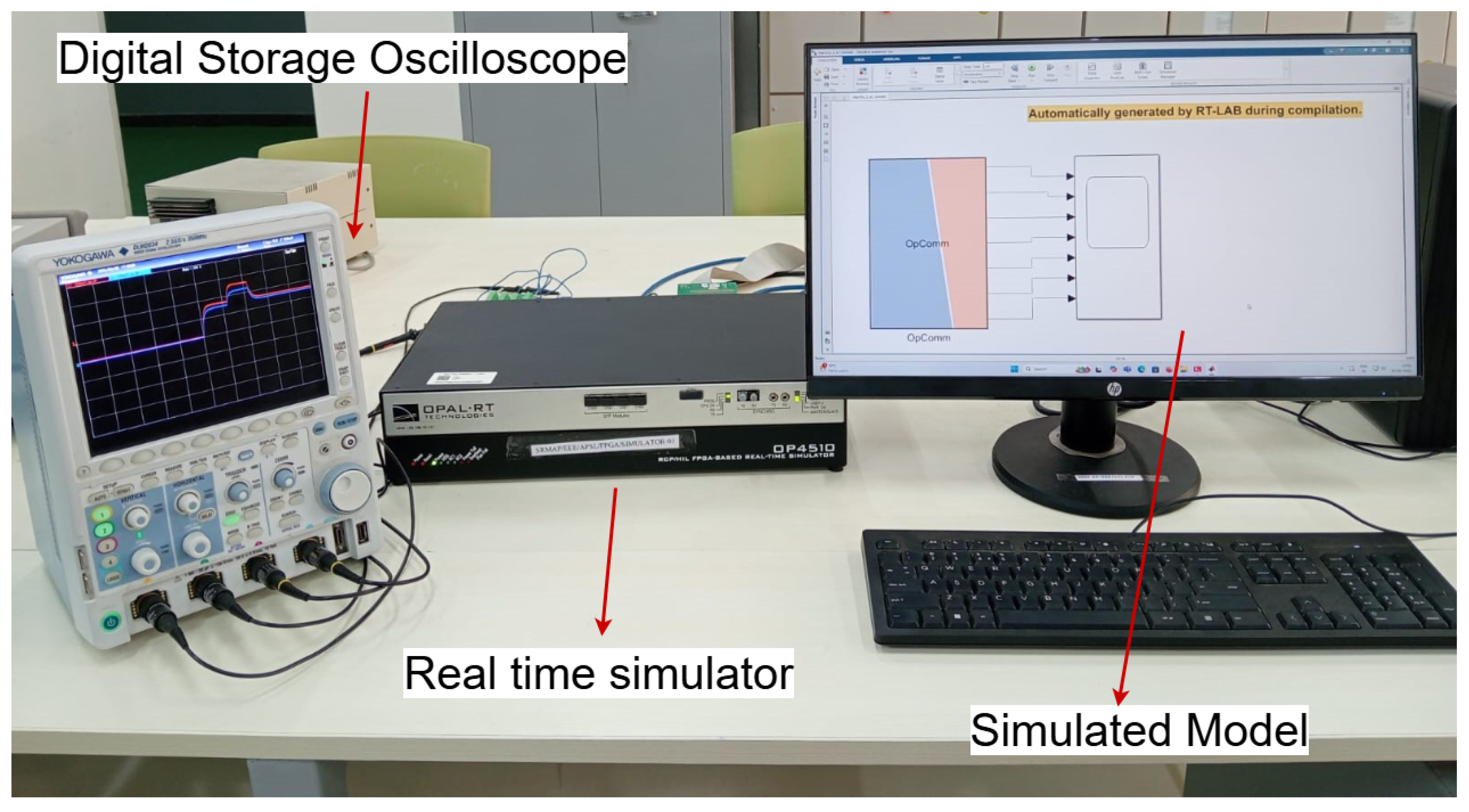
Table 1. The real-time simulation results were obtained using the OPAL-RT OP4510 digital simulator. The experimental verification setup is illustrated in
Figure 5; it comprises a host PC operating MATLAB 2022a alongside OPAL-RT OP4510 software, the target platform, and an oscilloscope for analyzing the proposed method. The sampling time for the MPC is taken as
= 10
s, and solver type is fixed-step and discrete-time solver. The comparative analysis between the proposed FCS-MPC integrated with a universal droop controller and the conventional PI-based droop controller is compared and evaluated, considering three different scenarios.
5.1. Case 1: When Line Impedance Is More Resistive in Nature; ,
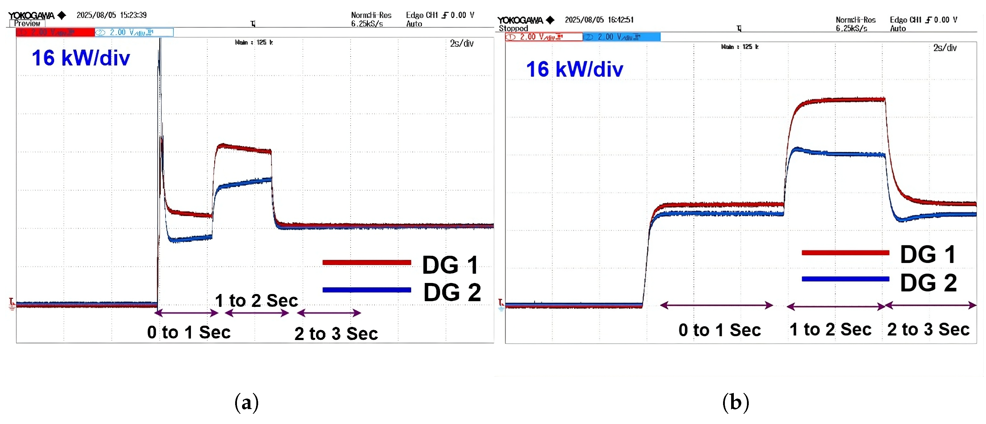
The active power response with the conventional controller in
Figure 6a shows relatively faster tracking of the load power reference, due to which high overshoot is observed in both DGs. In contrast, the FCS-MPC-based system shown in
Figure 6b demonstrates superior dynamic behavior. It exhibits better dynamic response in both DGs with a quick settling time without any overshoots. This is due to the predictive nature of FCS-MPC, which allows it to anticipate future states and generate optimal switching actions, thereby minimizing the effect of line impedance mismatch and enhancing real-time power distribution.
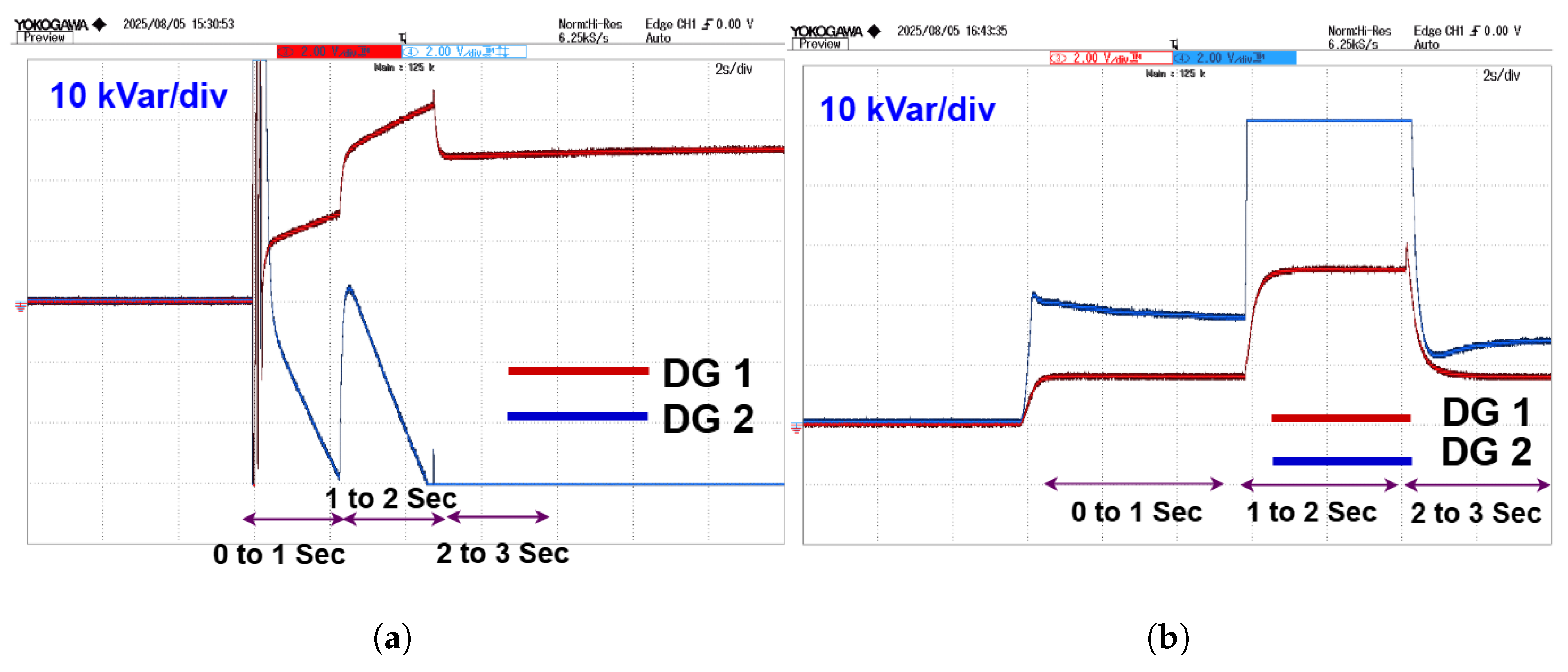
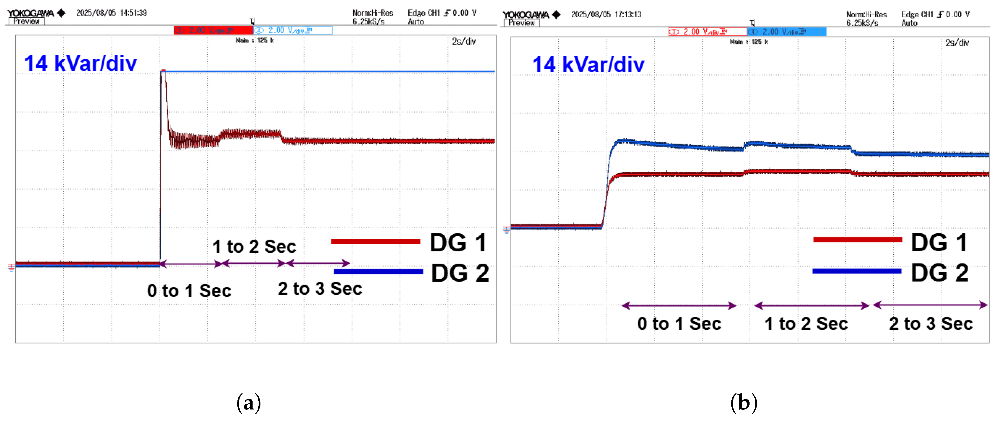
The reactive power response in the PI-controlled system is shown in
Figure 7a; it suffers from significant imbalances and prolonged oscillations during dynamic load change. The mismatch in reactive power sharing can lead to voltage imbalance and unnecessary stress on the inverters. Conversely, the FCS-MPC with universal droop control, which is shown in
Figure 7b, displays a more coherent and balanced reactive power profile. The transients are better damped, and the reactive power delivered by the DGs is more accurate confirming the controller’s effectiveness in handling the dominant resistive nature of the microgrid.
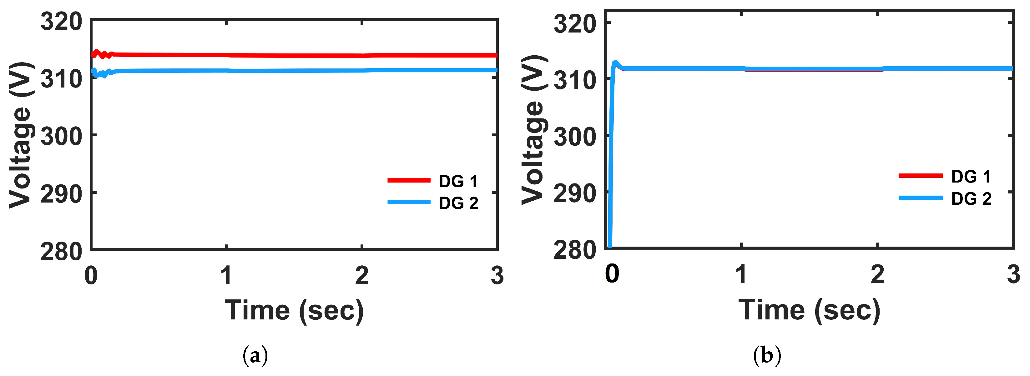
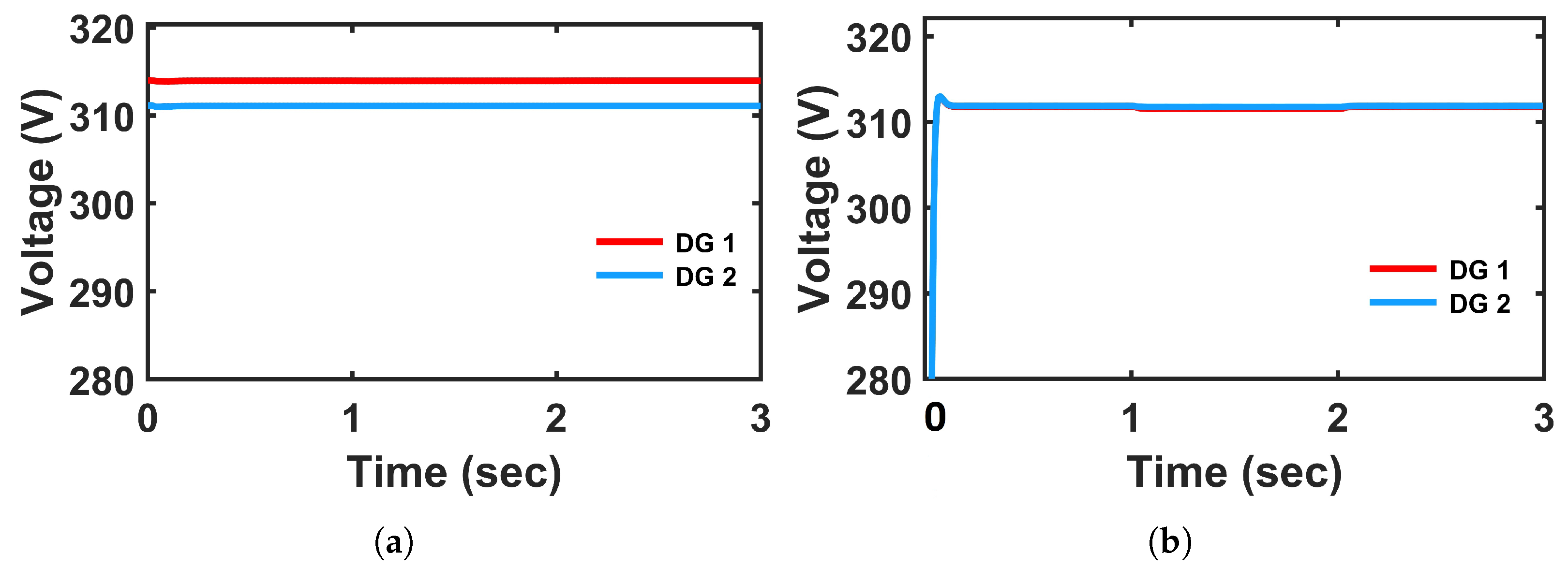
The voltage profiles shown in
Figure 8 further support this observation; the voltage exhibits more fluctuations during transitions and takes a longer time to settle around the nominal voltage of 311 V with PI-controlled system. Moreover, the voltage of DG 1 is maintained around nominal value (311 V), but DG 2 fails to do so and maintains around 314 V, which is shown in
Figure 8a. On the other hand, the FCS-MPC system shows significantly improved voltage tracking, with minimal overshoot and a faster return to nominal conditions as shown in
Figure 8b. It can be observed that load voltage of both the DGs is maintained well, close to nominal value (311 V), with the proposed controller. This is due to the fact that universal droop controller is integrated with FCS-MPC, which aids in adjusting the voltage references more adaptively, resulting in reducing the voltage deviation during disturbances.
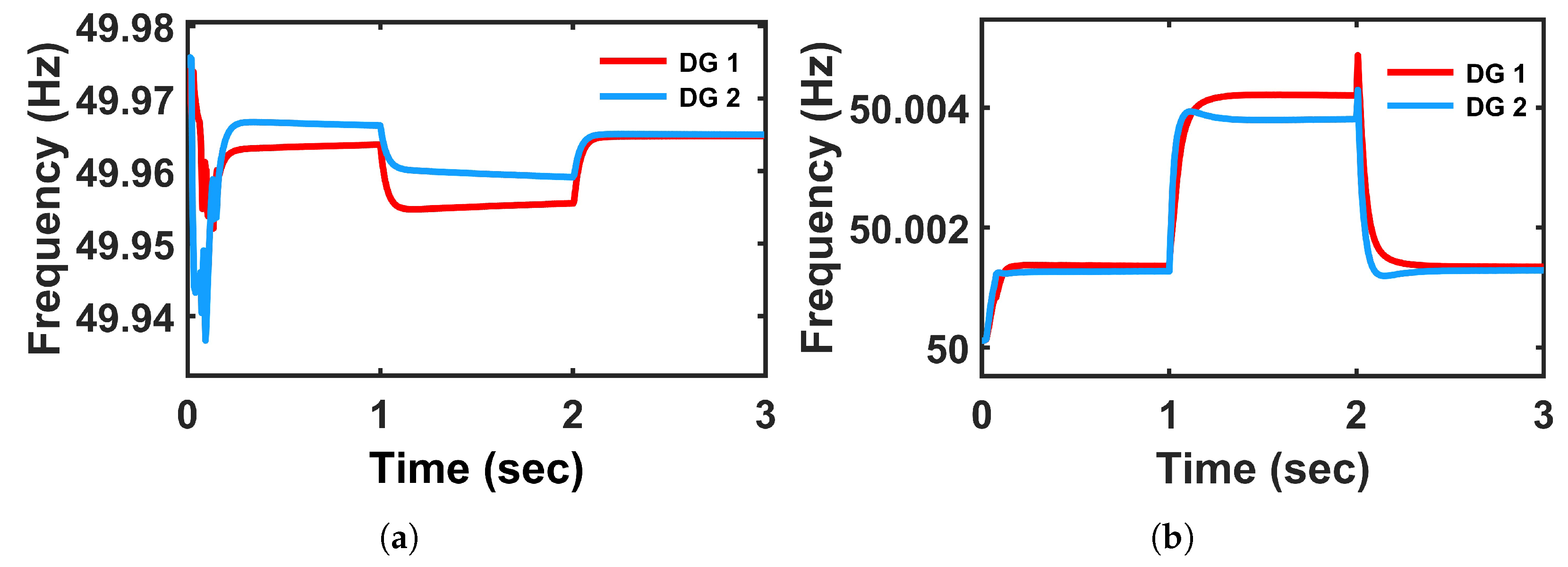
Frequency regulation is another critical metric for the stable operation of microgrids. The PI-based droop controller maintains frequency within acceptable limits as shown in
Figure 9a. However, it exhibits more fluctuations under load disturbances. The system temporarily dips or undershoots beyond the desired frequency (49.95 Hz), which can be detrimental under sensitive load conditions. However, the proposed controller maintains a frequency around 50 Hz even at load disturbances. The frequency of DGs is slightly increased by a margin of 0.0002, which reflects the enhanced operation of the proposed controller with minimal deviation and faster stabilization. This can be attributed to the model predictive mechanism, which continuously solves an optimization problem that considers both frequency and power references and ensures better synchronization and dynamic control. The frequency, load voltage, and DC-link voltage results are plotted using an opwrite file from OPAL-RT OP4510 library due to oscilloscope constraints in taking smaller values.
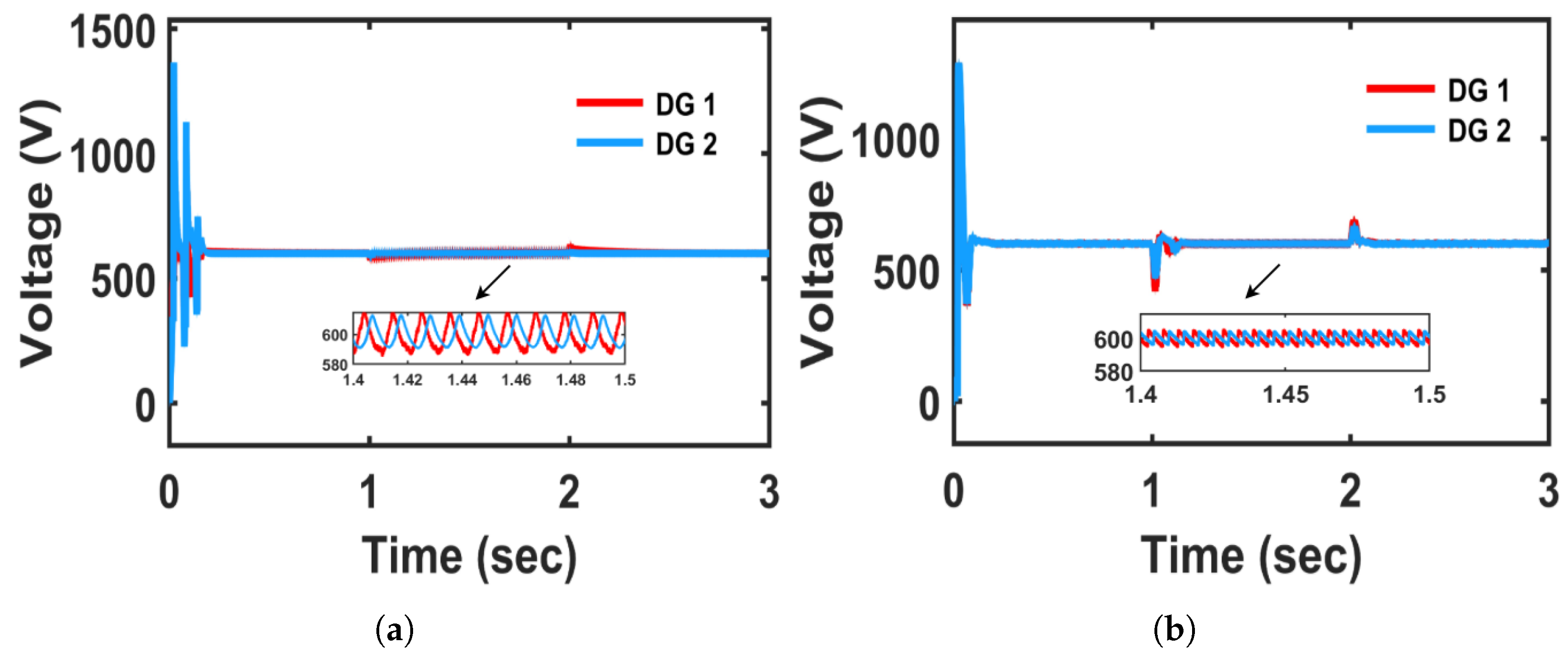
The DC-link voltage regulation for both DGs using the proposed and conventional controller reveals a significant improvement in system performance with the proposed method. The DC-link voltage with conventional controller illustrates considerable overshoot and pronounced oscillations during the startup transient, as well as load disturbances, which are shown in
Figure 10a. The PI-controlled system takes longer to settle and suffers from higher voltage ripple throughout the steady-state period, particularly between 1 s and 2 s, indicating sensitivity to disturbances and poorer dynamic performance as shown in the magnified part of
Figure 10a. In contrast, the DC-link voltage for both DGs exhibits a sharp initial transient but quickly settles around the reference value (600 V) with minimal oscillations and excellent steady-state stability with the proposed controller, which is shown in
Figure 10b. Although, during load disturbance, a small overshoot is observed, it settles quickly and reaches the reference value and the magnified part is shown in
Figure 10b. The MPC controller demonstrates fast recovery and smooth voltage tracking, confirming its robustness against load variations and external disturbances. Additionally, the voltage with conventional controller remains less stable compared to the proposed controlled case, which can adversely impact sensitive loads and overall system efficiency.
Therefore, the MPC controller outperforms the PI controller in terms of transient response, voltage settling time, and steady-state ripple minimization. The predictive nature of MPC enables proactive control actions, making it more suitable for maintaining DC-link voltage stability in dynamic microgrid environments.
5.2. Case 2: When Line Impedance Is More Inductive in Nature;
,
To test the performance analysis of the proposed controller, a more inductive transmission line impedance is considered. In a microgrid, if the line impedance between DGs is more inductive in nature, the transfer of active power from the DG to the load is adversely affected. The higher inductive reactance in the line limits the ability of the DG to inject active power into the system. The active power response, shown in
Figure 11, reveals that the PI-controlled system experiences a substantial overshoot, peaking during the initial transient period. Additionally, high-frequency oscillations persist during the settling phase, indicating poor damping characteristics. In contrast, the FCS-MPC-based system demonstrates a significantly more stable response. It exhibits a smooth rise in active power, settling quickly within 0.1 s, with minimal overshoot and no oscillations as shown in
Figure 11b.
In terms of frequency regulation, depicted in
Figure 12, the conventional PI controller shows a noticeable dip, dropping below 49.955 Hz and low-frequency harmonics during the load disturbances. On the other hand, the FCS-MPC controller maintains the frequency response above 50 Hz with both DGS throughout the system operation, which is shown in
Figure 12b. This is due to MPC’s predictive optimization, which ensures a more coordinated response among parallel inverters, enabling it to handle the high inductive impedance effectively and ensure frequency stability.
The reactive power performance shown in
Figure 13 further distinguishes the PI and FCS-MPC controllers. In the PI controller case, reactive power surges erratically, peaking and then exhibiting a series of oscillations before settling. These oscillations persist even in steady state, indicating the controller’s limited capability in handling dynamic reactive power demands under high line impedance. In contrast, the MPC-controlled system displays a fast-reacting and stable trajectory. It rises with minimal overshoot and settles quickly without noticeable oscillations. At load change instants, the MPC system continues to perform with superior transient rejection and fast settling, showing that it adapts well to dynamic load variations even in the presence of inductive elements in the distribution path.
Figure 14 presents the voltage behavior at the distributed generator. Under the PI-controlled system, the voltage experiences greater fluctuations initially, which is shown in
Figure 14a. Although DG 1 maintains a voltage close to the nominal level (311 V), DG 2 fails to do so and settles around 314 V instead. In contrast, the FCS-MPC system demonstrates significantly enhanced voltage tracking performance, as illustrated in
Figure 14b, with minimal overshoot and a quicker return to nominal voltage. It is evident that the load voltages of both DGs are effectively maintained close to the nominal value (311 V) when using the proposed controller.
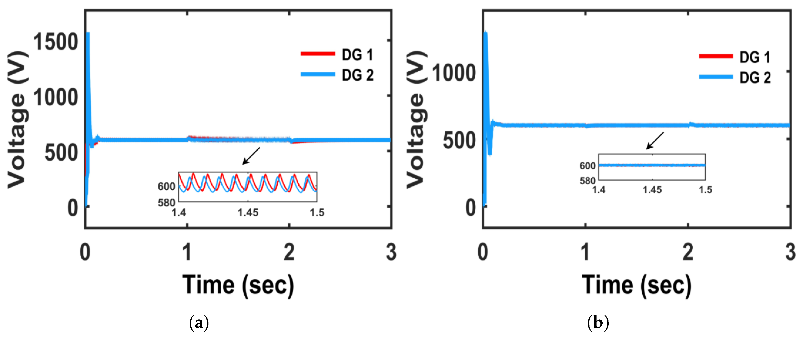
The DC-link voltage regulation for both DGs indicates an improvement in performance with the proposed controller compared to the conventional approach. As shown in
Figure 15a, the PI-controlled system exhibits significant overshoot and oscillations during startup and load disturbances, between 1 s and 2 s, as highlighted in the magnified view shown in
Figure 15a. In contrast,
Figure 15b shows that the proposed controller achieves faster settling around the reference value (600 V), with minimal oscillations and superior steady-state stability. Although no overshoots are observed during load disturbances, it quickly settles, which is shown in the magnified portion of
Figure 15b.
The results demonstrate that the FCS-MPC controller provides a robust and efficient control solution for inverter-fed microgrids operating under high transmission line inductance. It surpasses the conventional PI controller in terms of transient response, damping performance, steady-state accuracy, and disturbance rejection. These advantages validate the implementation of FCS-MPC as a more effective alternative to conventional control strategies in modern distributed energy systems.
5.3. Case 3: When Line Impedance Is Capacitive in Nature;
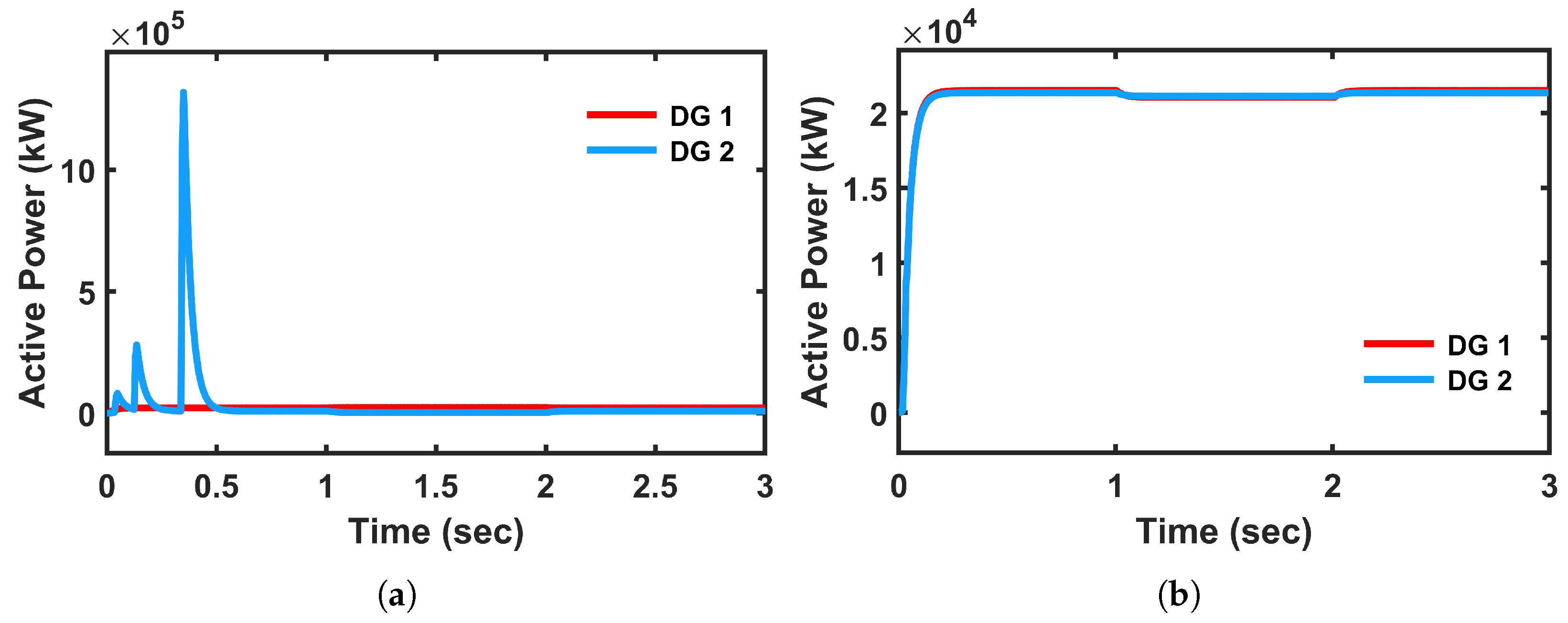
The active power response with both DGs is as shown in
Figure 16. DG1 with conventional controller shows relatively acceptable behavior, but DG2 becomes unstable during transients, exhibiting extremely large power oscillations, which is illustrated in
Figure 16a. In contrast, both DG1 and DG2 exhibit stable and coordinated operation, with smooth responses and negligible overshoot in all variables with proposed controller, which is shown in
Figure 16b. The oscillations with a conventional controller not only increase the risk of instability but also place severe stress on the system components. This indicates that PI struggles to maintain stability in a multi-DG environment, while FCS-MPC ensures proper coordination and robust performance for all units.
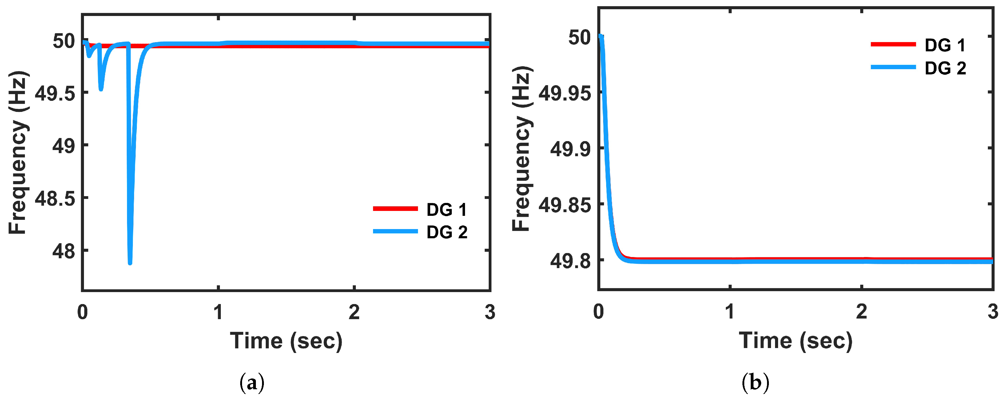
The frequency response with conventional control DG1 maintains a somewhat acceptable trajectory but DG2 experiences high-frequency oscillations with frequency drops to 48 Hz, leading to instability of the system, which is illustrated in
Figure 17a. However, the proposed controller is well maintained around 49.8 Hz with smooth decay, which is depicted in
Figure 17b. By comparing both the results, FCS-MPC successfully suppresses frequency deviations in both DGs, avoiding high-frequency oscillations.
The reactive power response with conventional controller is illustrated in
Figure 18a. The DG1 maintains a somewhat acceptable trajectory but DG2 experiences high-frequency oscillations, which lead to instability of the system. However, the reactive power with the proposed controller is well maintained, which is depicted in
Figure 18b.
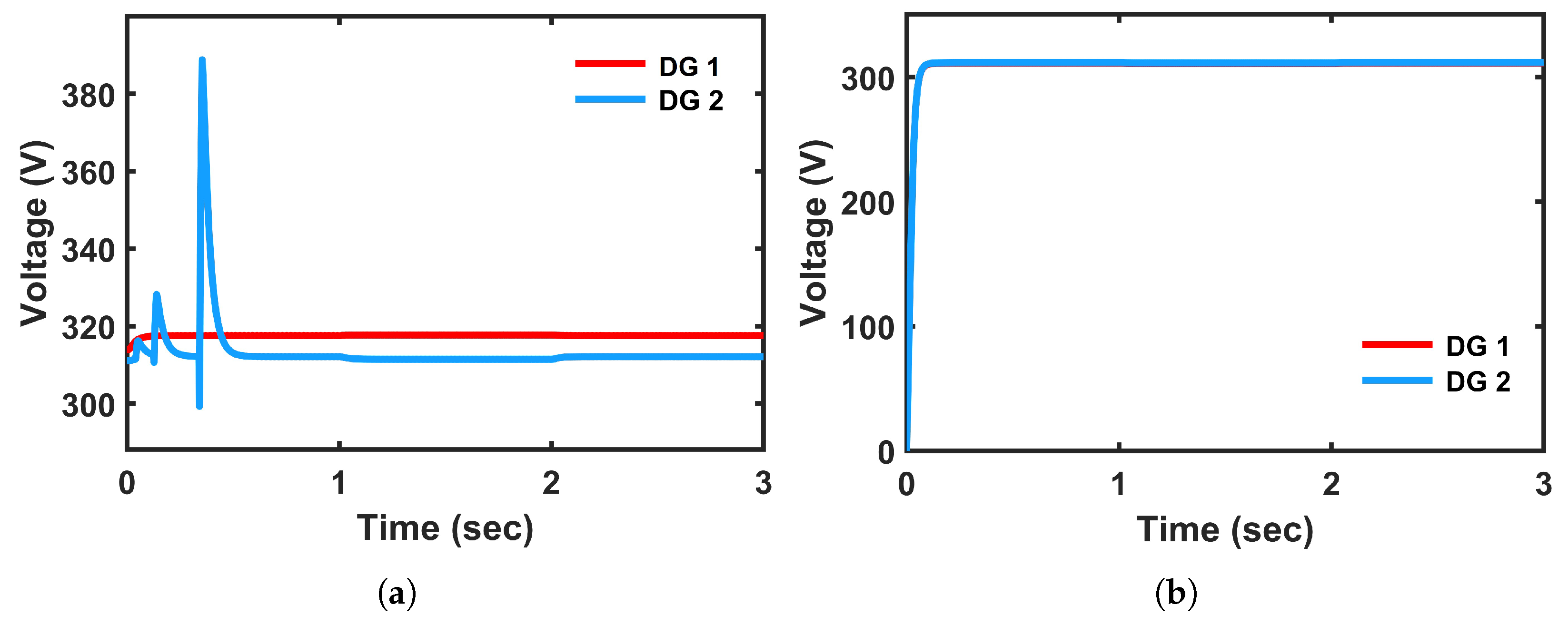
The voltage regulation with a conventional controller is depicted in
Figure 19a. The DG1 voltage regulation remains acceptable, while DG2 suffers from high-frequency oscillations. However, with proposed controller, both DGs stabilize near their reference voltages (around 311 V), which is shown in
Figure 19b. The oscillations with a conventional controller clearly show PI’s inability to maintain coordinated voltage control across multiple DGs, whereas FCS-MPC ensures robust and stable regulation for all DGs.
The DC-link voltage regulation for both DGs indicates an improvement in performance with the proposed controller compared to the conventional approach. As shown in
Figure 20a, the PI-controlled system exhibits significant overshoot and oscillations. In contrast,
Figure 20b shows that the proposed controller achieves faster settling around the reference value (600V), with minimal oscillations and superior steady-state stability. Although some overshoots are observed, it settles quickly.
5.4. Comparative Analysis
5.4.1. When Line Impedance Has Resistive Character
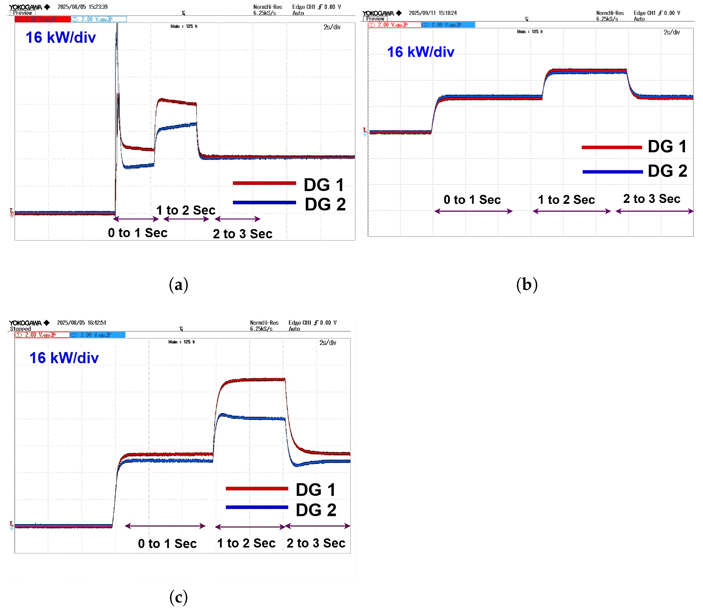
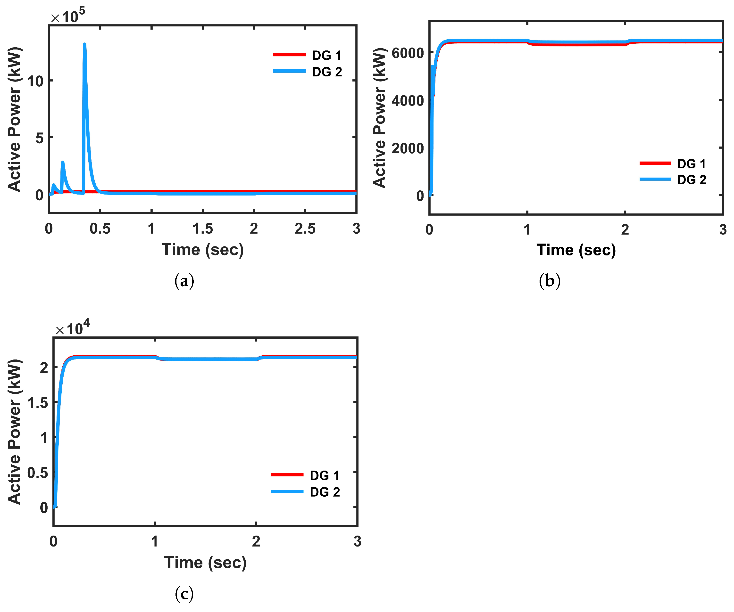
The active power response with the conventional controller in
Figure 21a shows relatively faster tracking of the load power reference due to which high overshoot is observed in both DGs. In contrast, the FCS-MPC-based system shown in
Figure 21b demonstrates superior dynamic behavior compared to conventional but both DGs are sharing equal power, which is not realistic.
Figure 21c shows the active power with the proposed method. It exhibits better dynamic response and realistic power sharing means DG 1 is sharing more power compared to DG 2. This is due to the predictive nature of FCS-MPC integrating with universal droop controller, which allows it to anticipate future states and generate optimal switching actions, thereby minimizing the effect of line impedance mismatch and enhancing real-time power distribution.
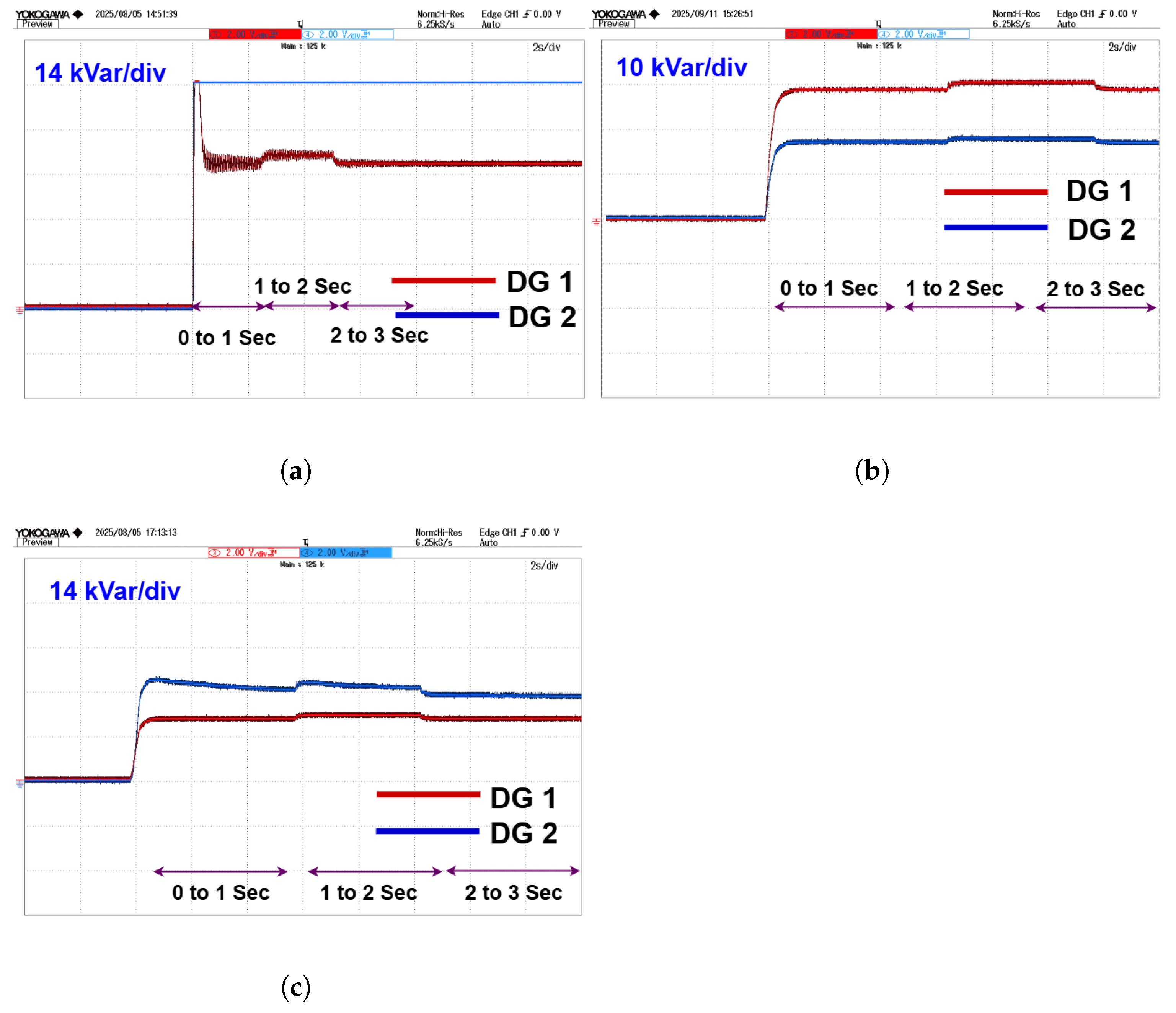
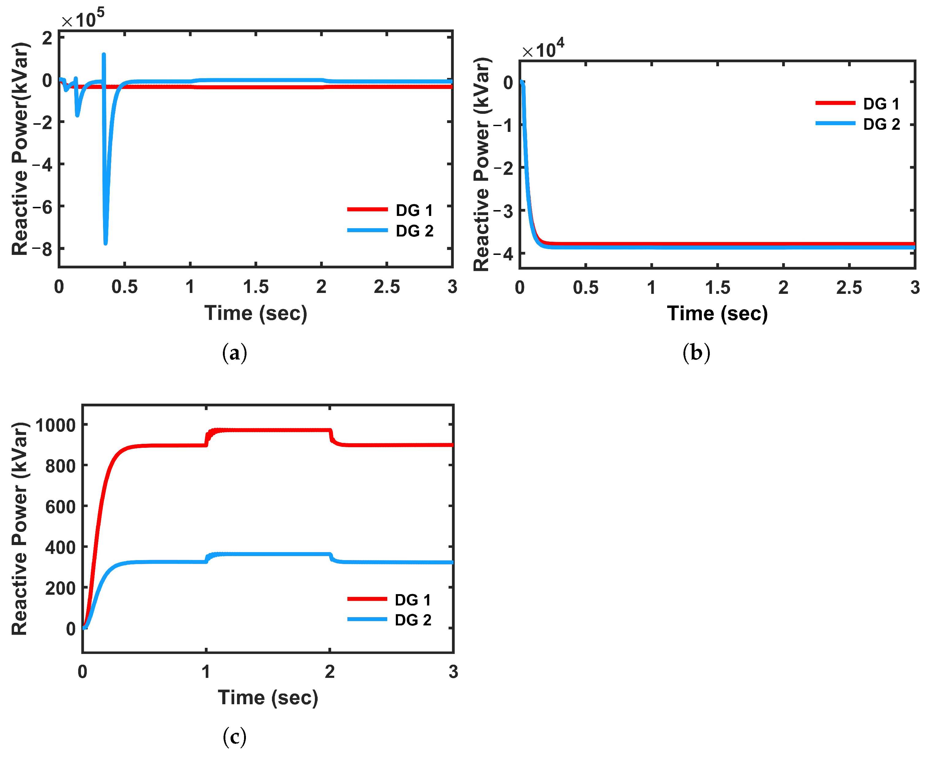
The reactive power response in the PI-controlled system is shown in
Figure 22a; it suffers from significant imbalances and prolonged oscillations during dynamic load change. The mismatch in reactive power sharing can lead to voltage imbalance and unnecessary stress on the inverters. The reactive power with FCS-MPC is shown in
Figure 22b. The reactive power of DG 1 becomes negative in order to maintain the required voltage. Conversely, the FCS-MPC with universal droop control, which is shown in
Figure 22c, displays a more coherent and balanced reactive power profile. The transients are better damped, and the reactive power delivered by the DGs is more accurate confirming the controller’s effectiveness in handling the dominant resistive nature of microgrid.
5.4.2. When Line Impedance Has Inductive Nature
The active power response with the conventional controller in
Figure 23a shows relatively faster tracking of the load power reference, due to which high overshoot is observed in both DGs. In contrast, the FCS-MPC and hybrid-based system shown in
Figure 23b,c demonstrates superior dynamic behavior. It exhibits better dynamic response in both DGs with a quick settling time without any overshoots. This is due to the predictive nature of FCS-MPC, with UDC allowing it to anticipate future states and generate optimal switching actions, thereby minimizing the effect of line impedance mismatch and enhancing real-time power distribution.
The reactive power performance in
Figure 24 highlights the differences among the PI, FCS-MPC, and proposed controllers. With the PI controller, reactive power rises erratically, reaching a peak and then undergoing a sequence of oscillations before settling. These oscillations persist even in steady state, reflecting the controller’s limited ability to manage dynamic reactive power demands under high line impedance, which is depicted in
Figure 24a. In contrast, the FCS-MPC-controlled system and proposed method demonstrate a fast and stable response. It increases with minimal overshoot, settles quickly, and shows no significant oscillations, which is shown in
Figure 24b,c. During load variations, the proposed method system continues to exhibit strong transient rejection and rapid settling, confirming its robustness in adapting to dynamic load changes despite the presence of inductive elements in the distribution path.
5.4.3. When Line Impedance Has Capacitive Nature
The active power response with the conventional controller in
Figure 25a shows relatively faster tracking of the load power reference, due to which high overshoot is observed in both DGs. In contrast, the FCS-MPC and hybrid-based system shown in
Figure 25b,c demonstrates superior dynamic behavior but with different power ratings. It exhibits better dynamic response in both DGs with a quick settling time without any overshoots.
The reactive power responses with conventional method and FCS-MPC are shown in
Figure 26a,b. In both the methods, reactive power becomes negative to maintain the voltage of the system. In contrast, the proposed method shares positive reactive power because of universal droop parameters, which is shown in
Figure 26c.
Overall, the results conclusively demonstrate the superiority of the proposed FCS-MPC combined with the universal droop controller over the conventional PI-based droop control. The predictive controller not only enhances the transient response of the system but also significantly improves steady-state performance across all operational parameters like active power, reactive power, voltage, and frequency. Furthermore, the universal droop strategy allows the FCS-MPC to maintain effective power sharing even in the presence of unequal line impedances, which is a challenge that the traditional PI controller struggles to overcome. It can be observed that the peak overshoot is high with conventional PI-based droop controller when compared to the proposed method.
These improvements are particularly crucial in practical microgrid deployments where real-time performance, fast adaptability to load variations, and robust operation under mismatched conditions. Therefore, the proposed control scheme provides a promising solution for enhancing the reliability, efficiency, and resilience of microgrids, making it well-suited for future distributed energy systems.
