Abstract
The operational stability and performance of dual active bridge (DAB) converters are dictated by an intricate coupling of electrical, magnetic, and thermal dynamics. Conventional modeling paradigms fail to capture these interactions, creating a critical gap between design predictions and real performance. A unified Port-Hamiltonian model (PHM) is developed, embedding nonlinear, temperature-dependent material physics within a single, energy-conserving structure. Derived from first principles and experimentally validated, the model reproduces high-frequency dynamics, including saturation-driven current spikes, with superior fidelity. The energy-based structure systematically exposes the converter’s stability boundaries, revealing not only thermal runaway limits but also previously obscured electro-thermal oscillatory modes. The resulting framework provides a rigorous foundation for the predictive co-design of magnetics, thermal management, and control, enabling guaranteed stability and optimized performance across the full operational envelope.
1. Introduction
The DAB converter has emerged as a cornerstone topology in modern power electronics, prized for its high power density, inherent ability to support bidirectional energy exchange, and galvanic isolation characteristics [1]. Owing to these features, it plays a central role in a diverse array of high-impact applications, ranging from renewable energy systems with integrated storage [2] and charging infrastructure for electric vehicles (EVs) [3,4] to the development of solid-state transformers (SSTs) for future smart grids and energy routers [5,6]. At the core of its operation lies a phase-shift control mechanism applied between its two active bridge legs. While this control principle appears intuitive, it governs a system with highly intricate dynamic behaviors, particularly under the broad variations in voltage and loading conditions characteristic of advanced applications. Delivering consistent efficiency, stability, and dynamic performance across this expansive operational space demands accurate and physically representative predictive modeling that transcends simplified assumptions.
Although extensive modeling efforts have been made, prevailing methods still suffer from critical deficiencies that compromise both their accuracy and generalizability. Approaches such as state-space averaging and its derivatives—including accurate small-signal models [7] and fundamental harmonic approximation (FHA) [8]—are inherently incapable of capturing the full dynamic behavior of the converter when operating outside the nominal region. They often omit important nonlinear phenomena, such as the magnetic core’s saturation under high-frequency excitation. Consequently, such simplifications yield imprecise estimates of current overshoots experienced by power semiconductors and lead to unreliable loss calculations under heavy loading or during fast transients [9]. Furthermore, averaged models struggle to delineate the precise boundaries of soft-switching regimes (ZVS/ZCS), which are pivotal for maximizing converter efficiency [10,11]. In contrast, detailed simulations based on the finite element method (FEM) can offer exquisite descriptions of magnetic flux distributions and parasitic interactions [12,13], yet the associated computational burden renders them unsuitable for tasks such as system-level transient simulations or control co-design.
A more profound drawback in mainstream modeling strategies lies in their insufficient integration of multi-physics interactions [14]. In high-power DAB converter systems, the coupling between electrical, magnetic, and thermal domains is not a secondary effect but a primary factor dictating reliability and long-term performance, a central theme in recent co-design methodologies [15,16]. Losses incurred in both magnetic and electrical elements lead to heat generation, which in turn elevates the operating temperature of magnetic materials. The thermal elevation modifies key magnetic parameters—such as saturation flux density and permeability —as well as alters winding resistance [17]. This feedback can obscure more subtle electro-thermal instabilities, including Hopf bifurcations that may arise well before any catastrophic thermal breakdown [18]. The challenge in analyzing these complex stabilities, especially in modern grid applications with inherent delays and weak grid conditions, underscores the limitations of traditional models [19,20].
To overcome the limitations identified above, this paper introduces a modeling paradigm grounded in Port-Hamiltonian (PHM) theory. Rooted in the principles of analytical mechanics, PHM offers a mathematically rigorous and physically grounded approach for representing complex multi-domain systems through an energy-based formalism [21,22]. It structurally decomposes the system into three constituent parts: energy-conserving interconnection dynamics characterized by a skew-symmetric matrix J, dissipative elements captured by a semi-definite matrix R, and a scalar Hamiltonian function H representing total stored energy. The structured formulation not only guarantees physical realism but also facilitates system stability analysis via energy-based Lyapunov functions. The value of PHM and related passivity-based approaches in the domain of advanced power electronics is a hot topic in contemporary research, enabling the formulation of robust nonlinear control schemes and the stability analysis of complex, multi-converter systems [23,24,25].
Leveraging the PHM framework, this study develops a detailed and integrative model of the DAB converter that encapsulates its electrical behavior, nonlinear magnetic effects, and temperature-dependent dynamics. The principal innovation lies in embedding a bidirectionally coupled representation of thermo-magnetic and thermo-electric feedback, alongside the inclusion of magnetic saturation. Section 1 provides a comprehensive review of the DAB converter’s operational principles and the Port-Hamiltonian modeling. Section 2 is dedicated to the detailed derivation of the multi-physics model. Section 3 presents the simulation and experimental validation of the proposed model. Section 4 concludes this paper by summarizing the key contributions.
2. The Principle of a DAB and PHM Theory
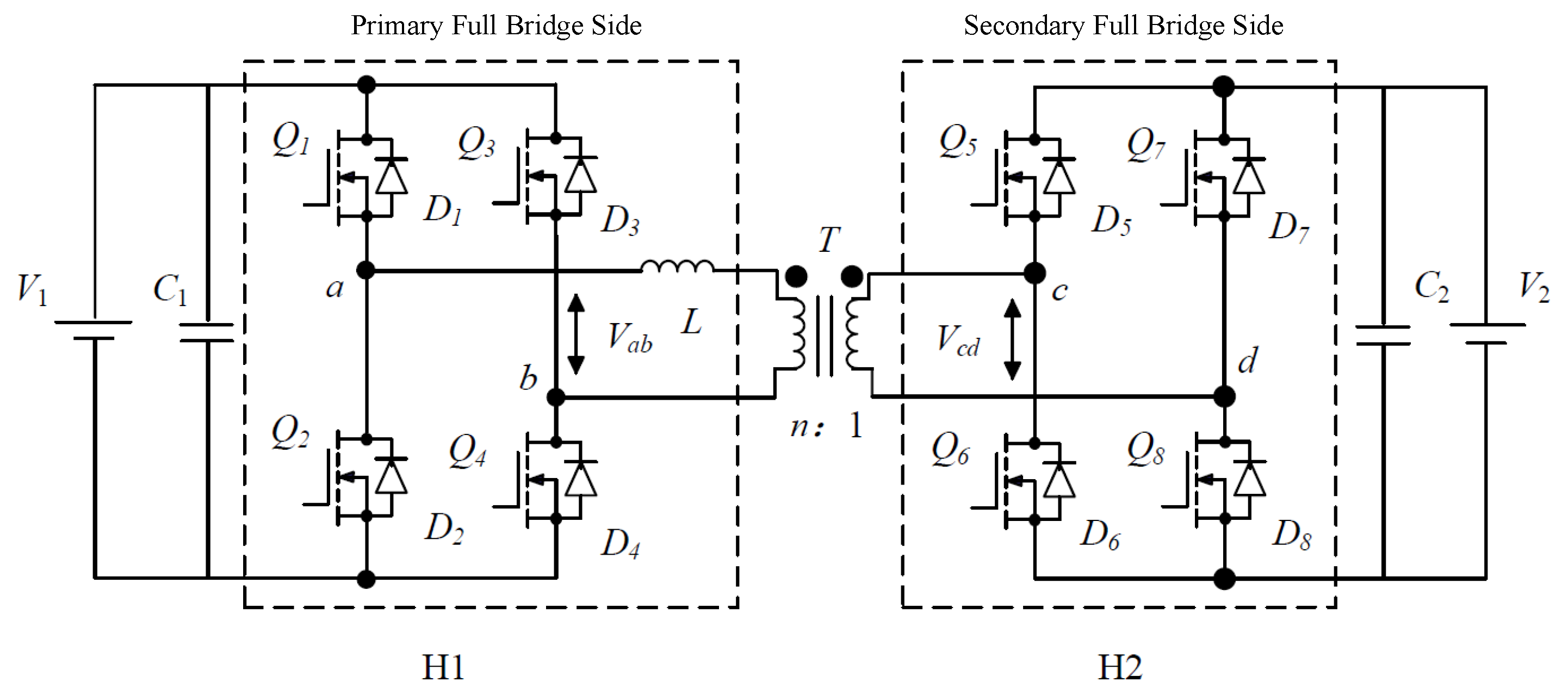
The DAB converter, depicted in Figure 1, features a symmetrical topology for bidirectional power transfer between two DC sources, and . The circuit consists of two full-bridge inverters, and , interconnected by a high-frequency transformer. The transformer provides galvanic isolation and voltage scaling via its primary-to-secondary turn ratio, . An inductor L, representing the aggregate of transformer leakage and any external series inductance, serves as the primary energy transfer element. By generating high-frequency quasi-square-wave voltages, and , at their respective AC terminals, the bridges facilitate power exchange through the inductor current, .
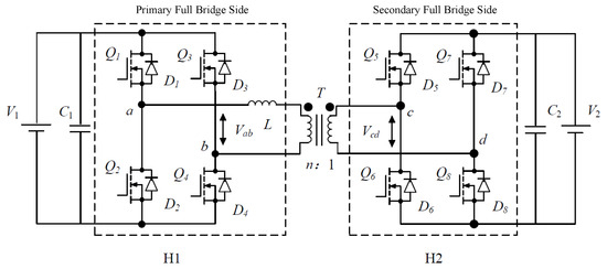
Figure 1.
Topology of a DAB converter.
The operating principle of a DAB converter is based on controlling the phase shift, , between the inverter output voltages. Under the conventional single-phase-shift (SPS) modulation, both bridges operate with a fixed 50% duty cycle. The power flow is regulated by controlling the phase displacement, which imposes a voltage across the inductor, , where is the secondary voltage reflected to the primary side. This voltage drives a periodic inductor current, and the average power, P, transferred over a switching period is given by
where is the normalized phase-shift ratio. By precisely manipulating D, both the magnitude and direction of power flow can be continuously controlled, making the DAB converter exceptionally versatile.
The PHM framework provides a structured, energy-based approach for modeling multi-domain physical systems. Unlike traditional input–output models, the PHM formalism explicitly represents a system’s internal energy storage, power-conserving interconnection, and dissipative processes, offering deep insights into its physical consistency, stability, and control properties. The state-space representation describes a general nonlinear PHM:
where x is the state vector of energy variables, and is the Hamiltonian, a scalar function representing the system’s total stored energy. Its gradient, , defines the co-energy variables. The skew-symmetric interconnection matrix models the internal, power-conserving energy exchange, while the positive semi-definite dissipation matrix models irreversible energy losses. The input matrix maps external control inputs u to the state dynamics, with y being the corresponding power-conjugated output.
The framework of DAB converters is effective as it unifies the electrical, magnetic, and thermal domains into a coherent model. The total Hamiltonian for a coupled electro-thermo-magnetic model is the sum of the energies stored in each domain:
where represents the energy stored in the DC-link capacitors, represents the energy transfer inductor and the magnetizing inductance of the transformer, and represents the thermal energy stored in the physical mass of the converter’s components.
The key advantage emerges in , which captures the switching behavior controlled by the phase-shift ratio D, and the gyroscopic coupling between the electrical MMF and the magnetic flux rate. Furthermore, naturally incorporates both winding resistance losses and core losses, which in turn generate the entropy flow that drives the thermal subsystem. serves as a natural candidate for a Lyapunov function. The time derivative of the Hamiltonian reveals the power balance of the system:
The result is derived noting that due to the skew-symmetry of . Equation (4) provides a physically intuitive statement: the rate of change in the stored energy equals the net power supplied through the ports minus the power dissipated internally. For a closed system (), , directly proving stability.
Equation (4) provides a structurally superior method for estimating power loss distribution more accurately. The total dissipated power, , is not a lumped parameter but is calculated from a physically partitioned dissipation matrix, . The matrix separates the origins of loss, such as electrical winding resistance () and magnetic core losses (). Consequently, conduction losses are not computed from averaged or idealized waveforms but are determined instantaneously using the high-fidelity simulated currents and incorporating the crucial thermo-electric feedback via temperature-dependent resistance, . Similarly, magnetic losses are derived from first principles by quantifying the energy dissipated within the magnetic subsystem each cycle, an approach that inherently accounts for the non-sinusoidal flux excitation and the temperature-dependent B-H characteristics of the core. The circumvents the well-known inaccuracies of empirical formulas, resulting in a quantitative, physically grounded loss budget that is significantly more accurate than that derived from conventional, decoupled modeling techniques.
3. Proposed PHM Model of DAB
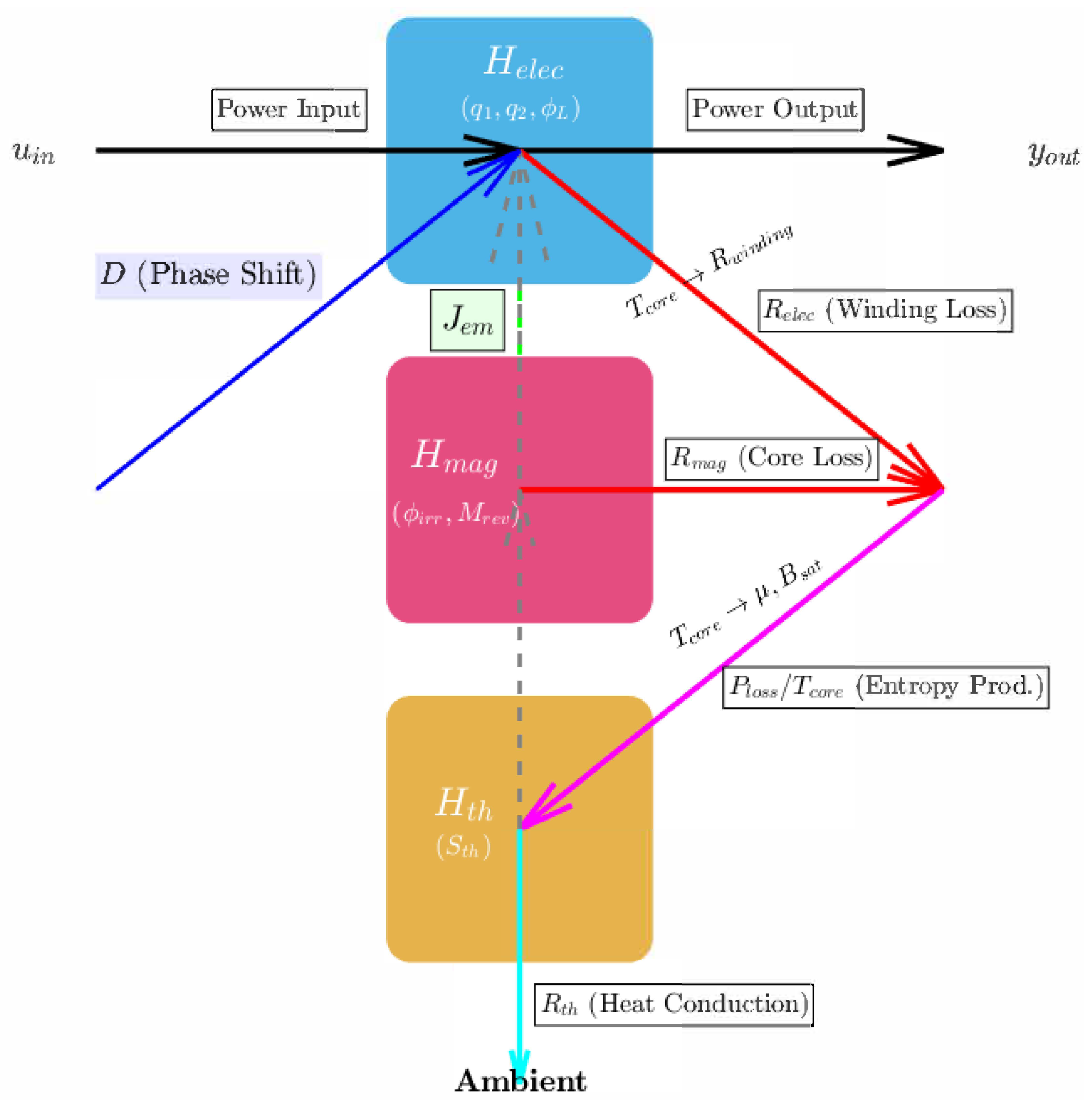
Figure 2 illustrates the proposed PHM of the DAB converter, which couples its electrical, magnetic, and thermal dynamics. The framework decomposes the system into three interconnected physical domains, each defined by its respective Hamiltonian and energy-based state variables. The multi-physics interactions at the core of the model are captured through structured energy-conserving and dissipative pathways. The electrical and magnetic domains are interconnected via a power-conserving gyrator matrix, , which represents the ideal energy conversion between magnetomotive force and magnetic flux, forming the basis of transformer action. Irreversible energy losses are explicitly modeled as dissipative pathways governed by R. Electrical energy is dissipated as , while magnetic energy is dissipated as . These loss powers converge to generate entropy, represented by flow, which serves as the input to the thermal domain . The thermal energy is defined by entropy , which is ultimately dissipated to the ambient environment through the thermal resistance . The core temperature directly influences the parameters of both the magnetic and electrical domains.
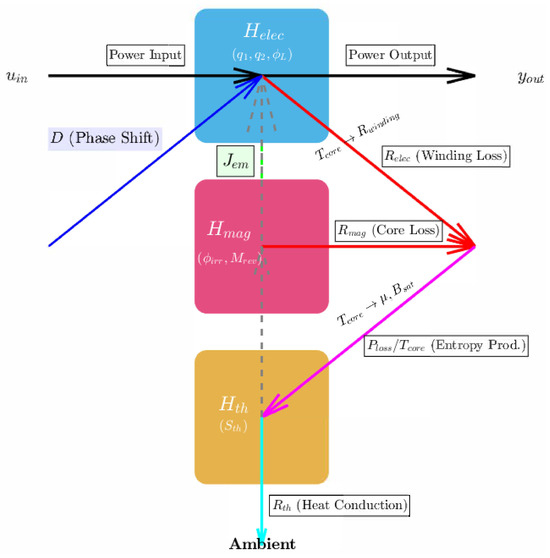
Figure 2.
Port-Hamiltonian structural network energy flow and information coupling in the DAB system.
3.1. Derivation of the Thermo-Magnetically Coupled Permeability
The magnetic permeability of ferromagnetic materials is inherently nonlinear with respect to the applied magnetic field strength due to saturation and simultaneously exhibits strong temperature dependence, particularly as the material approaches its Curie temperature. Consequently, to maintain thermodynamic consistency within an energy-based framework and to enable dynamic simulation under thermal drift, the permeability must be modeled as a smooth, continuously differentiable function of both magnetic field and temperature.
The saturation flux density , a key descriptor of the material’s nonlinear behavior, diminishes monotonically with temperature and asymptotically approaches zero as the core temperature approaches the Curie point :
where is the reference saturation flux at ambient temperature. In the low-field regime, the material responds linearly with an initial permeability , where is interpolated from manufacturer data using a smooth polynomial fit to ensure differentiability, typically expressed as
The initial permeability defines the slope of the curve at infinitesimal fields and captures the material’s softening under thermal excitation. The temperature derivative holds across the operational range for most soft magnetic materials, ensuring that the magnetic energy function is thermodynamically consistent. To account for saturation effects, the flux density as a function of magnetic field strength and temperature is modeled using an arctangent function:
To integrate this material-level nonlinearity into the circuit-level model of the DAB transformer, the magnetic field strength is mapped to the magnetizing current . The corresponding dynamic magnetizing inductance is then given by
Equation (9) reveals that the inductance softens as the core saturates under high excitation and as it heats toward . The quadratic term in the denominator ensures a smooth degradation of inductance, a mathematically robust feature that prevents numerical instability and guarantees physical consistency in the presence of thermal demagnetization. To complete the constitutive characterization, the stored magnetic co-energy is derived by integrating the function with respect to H, yielding the temperature- and field-dependent energy density:
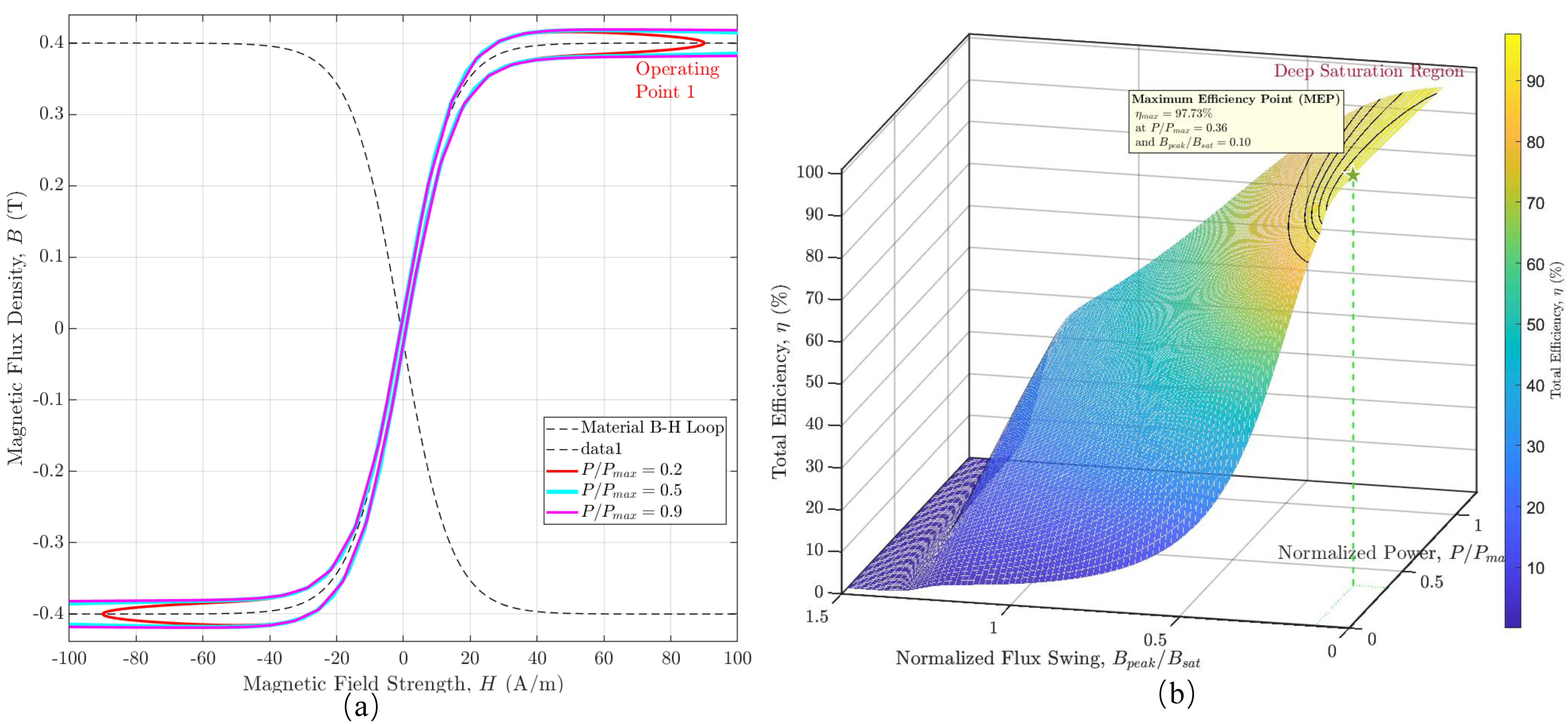
Figure 3 presents a compelling visualization of the operational dichotomy governed by the nonlinear physics of the magnetic core. In Figure 3a, each colored trajectory represents the magnetic core’s state evolution over a single switching cycle at a specific power level. At low power (), the operational loop is small and confined to the linear region of the B-H curve, indicating minimal core losses and low magnetizing currents. As the power demand increases (), the trajectory is forced to expand, encompassing a significantly larger area. The geometric expansion is a direct visual analog to increased hysteretic and eddy-current losses. Critically, at high power levels, the loop’s apices extend into the knee of the B-H curve, signaling the onset of magnetic saturation. This visualization transforms the abstract concept of power transfer into a tangible magnetic stress test, where the area enclosed by the operational loop serves as a direct proxy for the per-cycle energy dissipated within the core.
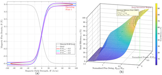
Figure 3.
(a) DAB core operating trajectory vs. power level on the material B-H Plane. (b) DAB efficiency vs. power throughput and core saturation.
Figure 3b shows the systemic level by charting the converter’s total efficiency as a function of both normalized power throughput and the normalized magnetic flux swing, which serves as a direct indicator of core saturation. In the region of low-to-moderate flux swing, the efficiency surface forms a gentle plateau, peaking at a maximum efficiency point where conduction and core losses are optimally balanced. However, as the operating point is pushed beyond this region, forcing the flux swing toward and beyond saturation, the efficiency plummets precipitously. The cliff is a manifestation of catastrophic loss escalation, where deep saturation causes the magnetizing inductance to collapse, leading to large spikes in magnetizing current. The overlaid iso-efficiency contours serve as design guides, defining the safe operating area for high-efficiency performance. The model provides an intuitive tool for co-designing the DAB’s control strategy and magnetic components, enabling engineers to maximize power density by operating near the performance peak without falling off the efficiency cliff into the abyss of thermal runaway.
3.2. The Coupled Electrical Subsystem with an RL Load
To model a realistic application, such as a downstream converter or motor drive, an RL load is considered at the output. This introduces a new energy storage element, the load inductor , which fundamentally alters the system’s dynamics. The PHM accommodates this change through a systematic augmentation of the electrical subsystem model.
The original energy coordinates are augmented with a new state variable, the flux linkage of the load inductor, . The augmented electrical state vector is thus defined as . Consequently, the electrical subsystem Hamiltonian must be expanded to include the energy stored in this new element:
The gradient of this augmented Hamiltonian, , yields the co-energy variables, which now include the load current, . The dynamics of this new state, governed by Kirchhoff’s voltage law for the load circuit, (), are integrated into the system’s structural matrices.
The switching functions are defined as and . Then the interconnection matrix must be expanded to a 5 × 5 dimension to capture the power-conserving energy transfer from the output capacitor () to the load inductor. The augmented skew-symmetric interconnection matrix, , is given by
The dissipation matrix, , is also augmented to model the irreversible energy losses, which now include the load resistance, . The original resistive load term () is removed, as the load’s dissipative and energy-storing aspects are now modeled explicitly.
Note that the magnetizing branch is assumed to be lossless within this electrical subsystem; its associated core losses are accounted for as a dissipative output from the magnetic domain. This augmented formulation provides a physically robust and structurally insightful foundation for analyzing the converter’s interaction with dynamic, realistic loads.
The external power supplied by the input DC source is represented by the input port . For an ideal voltage source providing a current , this port vector is defined as in the augmented 5 × 5 system. The resulting model, now structurally incorporating the RL load dynamics, is fully coupled with the nonlinear, thermo-sensitive magnetic characteristics, providing a physically robust foundation for advanced stability and control co-design.
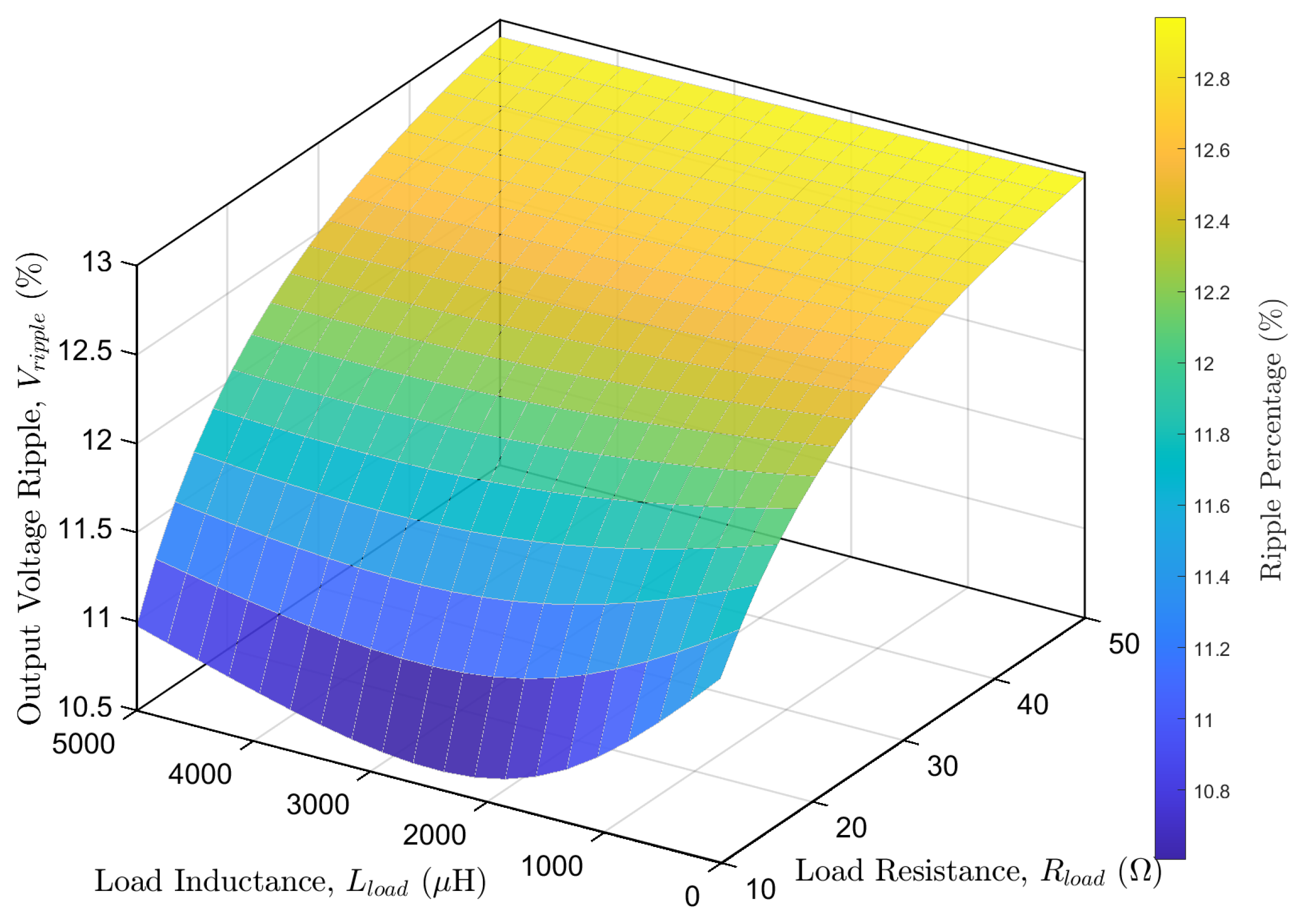
The augmented PHM enables a parametric analysis of the converter’s performance under RL load conditions. Figure 4 presents a performance manifold derived from the model, which maps a critical key performance indicator, the output voltage ripple (), as a function of the load’s constitutive parameters, its resistance, , and its inductance, . The map provides a tool for the co-design of the converter’s control strategy, allowing for the systematic optimization of the power stage to meet specific application requirements, such as minimizing voltage ripple for sensitive loads, thus ensuring robust performance across the desired operational envelope.
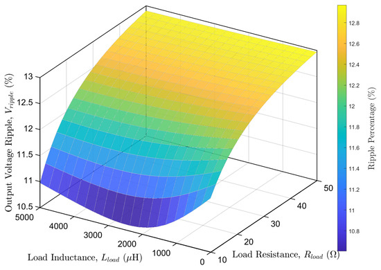
Figure 4.
Performance manifold of output voltage ripple as a function of RL load parameters.
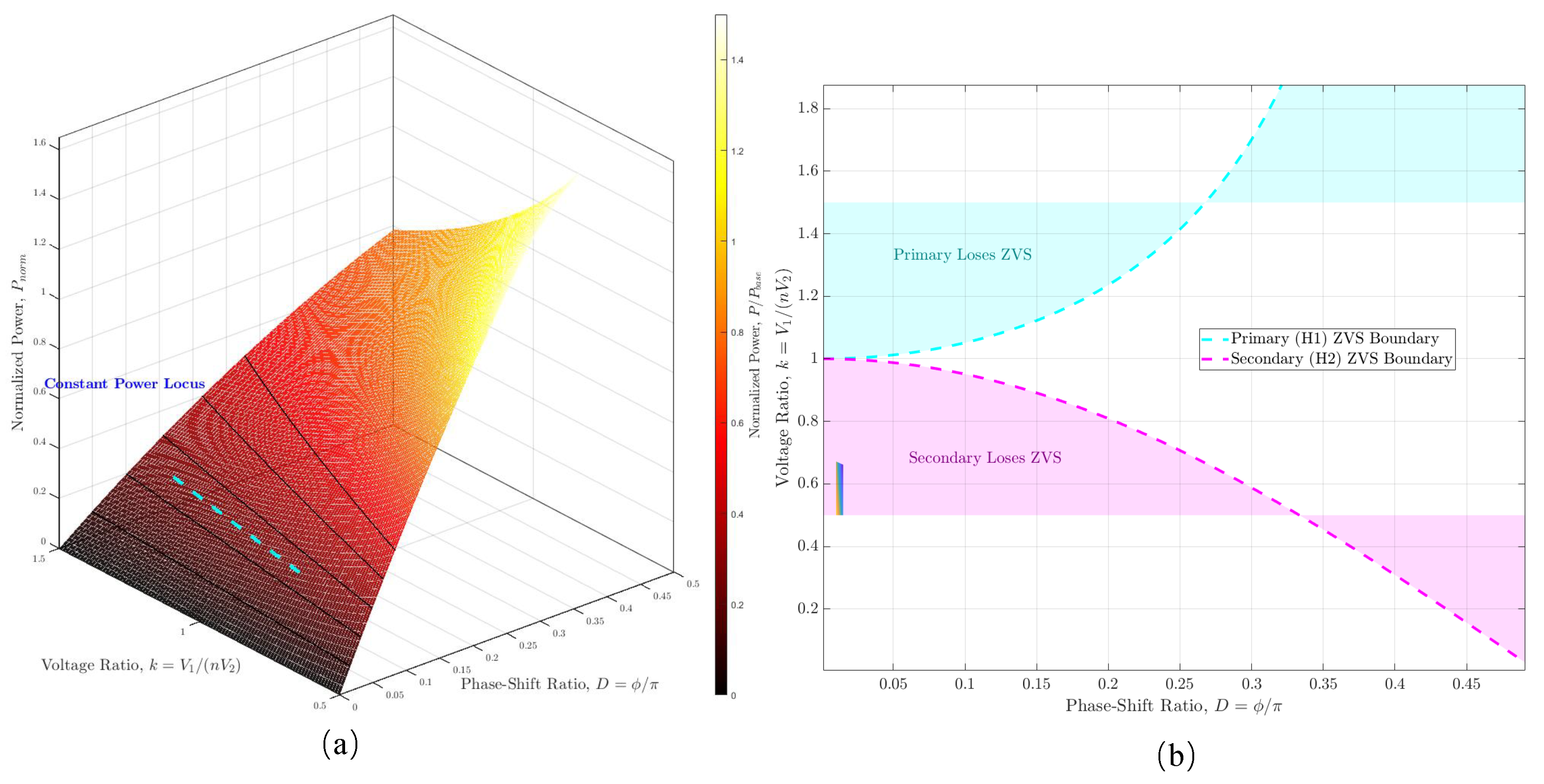
Based on the Eeectrical model, Figure 5a depicts the power manifold, a three-dimensional surface illustrating the normalized power throughput as a function of D and the voltage conversion ratio k. This geometric representation, derived directly from the system’s PHM, reveals the fundamental control-to-output mapping. The surface’s topology delineates the achievable power for any given operating condition, while overlaid iso-power contours define the control trajectories necessary for regulation. The highlighted constant power locus exemplifies a practical control law, tracing the path the controller must navigate in the space to maintain a constant output power despite variations in the voltage ratio. Figure 5b translates this parametric understanding into a practical design map by projecting the performance onto ZVS operational plane. The dashed lines represent the critical boundaries for achieving soft switching, a prerequisite for high-efficiency operation. The cyan boundary delineates the region where the maintains ZVS, while the magenta boundary does the same for . The shaded areas thus represent hard-switching regions, where switching losses increase dramatically. The intersection of the two ZVS-enabled regions defines the optimal operating corridor. The figure illustrates the inherent design trade-off: maximizing power throughput, which often requires larger values of D, can push the operating point across the ZVS boundaries, thereby compromising efficiency.
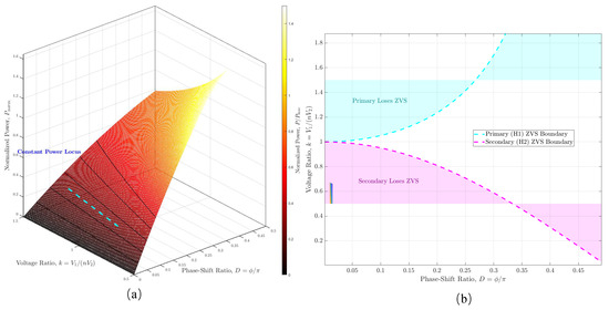
Figure 5.
(a) The geometry of the DAB power manifold. A PHM-derived parametric surface. (b) DAB efficiency map and ZVS operating regions.
3.3. The Unified Coupled PHM Model
The unified model is constructed from three fundamental subsystems, each representing a distinct physical domain with its own energy storage (Hamiltonian), internal structure, and dissipative properties.
The electrical subsystem (): As previously derived, the subsystem describes the energy stored in the electric fields of capacitors and the magnetic fields of leakage inductors. Its state vector is . The Hamiltonian is . Its dynamics are governed by a PHM equation with a state-dependent interconnection matrix representing the switching action, and a dissipation matrix for winding and load losses.
The magnetic subsystem (): The subsystem models the energy dynamics within the magnetic core. The state vector, , encapsulates the internal magnetic states, including the magnetizing flux linkage and any states required for hysteresis modeling. Its dynamics are governed by the Hamiltonian and a dissipation matrix that models core losses.
The thermal Ssubsystem (): The subsystem describes the thermal energy of the core. The natural state variable is the entropy, . The Hamiltonian is simply the core temperature, . Its dynamics are governed by the second law of thermodynamics, describing entropy production from internal losses and entropy transfer to the ambient environment.
The essence of the unified model lies in the formulation of the inter-domain coupling structure. These couplings are not ad hoc but are derived from fundamental physical laws of energy conversion and power balance. The state vector of the unified system is the concatenation of the subsystem states:
Therefore, the dynamics of the full system can be written in a partitioned PHM form:
The electro-magnetic coupling is power-conserving and is modeled by the off-diagonal gyrator block . The magnetizing current, a component of the primary current, generates a magnetomotive force , which acts as the effort variable for the magnetic domain. Conversely, the rate of change of the magnetizing flux, , induces a voltage that acts as a co-energy source upon the electrical domain. This reciprocal relationship, captured by the skew-symmetry , mathematically guarantees that the net power exchanged between the domains is identically zero.
The electro-magneto-thermal coupling is dissipative and represents the irreversible conversion of electromagnetic energy into heat. The power dissipated in the electrical and magnetic subsystems, , becomes the source of entropy generation for the thermal subsystem:
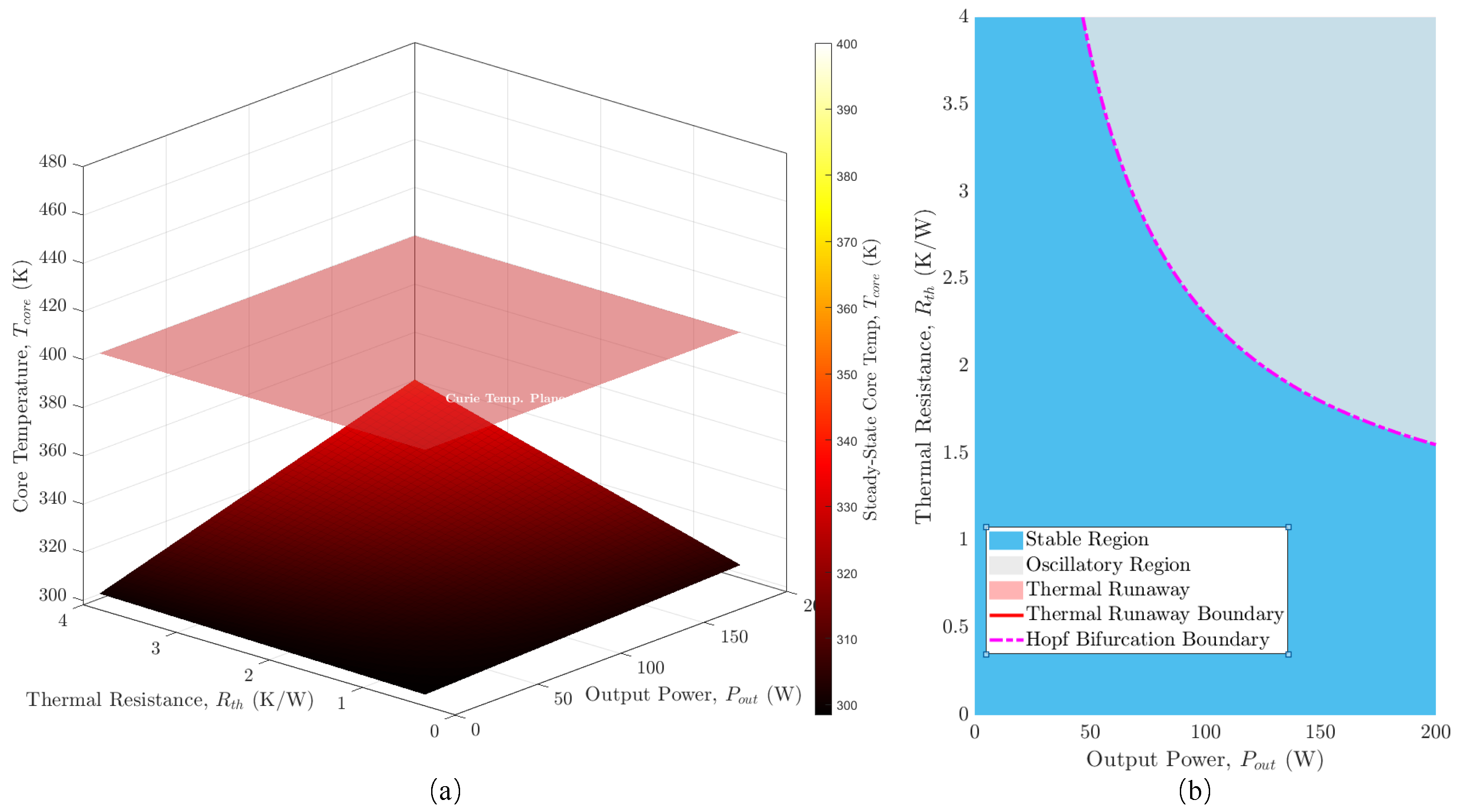
The resulting entropy production rate, , serves as a state-dependent input to the thermal domain, forming the forward path of the multi-physics feedback loop. The steady-state temperature surface shown in Figure 6a is the locus of points where this entropy generation is exactly balanced by heat conduction to the ambient environment, i.e., .
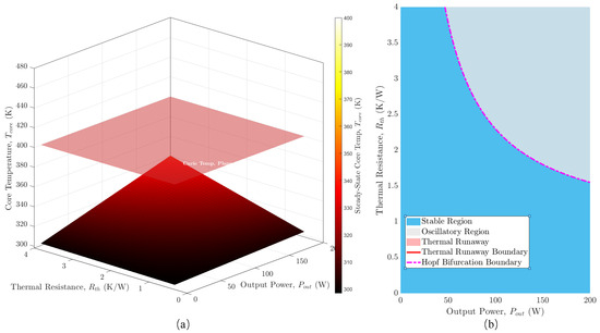
Figure 6.
(a) Thermal equilibrium surface vs. power and cooling. (b) System stability phase map under multi-physics voupling.
The thermo-to-electromagnetic coupling constitutes the critical feedback path, where the thermal state modulates the properties of the electrical and magnetic domains. As captured in the formulation of the total Hamiltonian , parameters within the matrices and and within the magnetic Hamiltonian are all functions of . The parametric dependence means that the system’s Jacobian matrix, used for stability analysis, will contain non-zero off-diagonal terms, , which are responsible for the complex stability behavior visualized in the phase map in Figure 6. The strength of this feedback determines whether the system converges to a stable equilibrium, crosses a Hopf bifurcation boundary into a sustained oscillation, or surpasses a static thermal runaway boundary.
Figure 6a illustrates the thermal equilibrium surface, which defines the steady-state core temperature as a function of and . This manifold represents the locus of points where heat generated from internal losses is precisely balanced by heat dissipation to the ambient environemnt. The superimposed Curie temperature plane represents a critical physical threshold. The intersection of these two surfaces defines the thermal runaway boundary, beyond which no stable thermal equilibrium exists, leading to catastrophic failure of the magnetic component. Therefore, the unified PHM model provides a complete and physically consistent mathematical foundation for the observed macroscopic stability characteristics.
Figure 6b translates this analysis into a comprehensive system stability phase map, classifying the converter’s long-term dynamic behavior across the operational space defined by output power and thermal resistance. The map reveals three distinct regions. The stable region guarantees convergence to a unique, steady operating point. The thermal runaway boundary demarcates the zone of static instability. Most significantly, the analysis reveals a Hopf bifurcation boundary. Crossing this boundary drives the system into an oscillatory region, where it no longer settles to a steady state but instead enters a sustained electro-thermal limit cycle. The map provides a critical design tool, demonstrating that system stability is not merely a static thermal limit but a complex dynamic property and that robust operation requires remaining within a more constrained region than thermal considerations alone would suggest.
Considering classical isolated power stages(PSFB/LLC), PSFB offers simplicity but narrower ZVS range at light load; LLC attains wide soft-switching but is sensitive to tank tolerances. The DAB with PHM-based synthesis provides a geometric design law in with explicit multi-physics stability limits (Figure 6). Complexity increases modestly for two bridges with isolation, but the operating corridor is transparent and robust under saturation and temperature variations.
4. Simulation and Experimental Validation
4.1. Simulation Results
In order to validate the high-fidelity predictive capabilities of the PHM model and to contrast its performance with conventional modeling approaches, a comprehensive simulation platform for DAB converters was established within the PLECS environment. The DAB operates in a DC–DC application where the output is connected to a regulated DC bus, which is a common scenario in applications such as battery charging systems and solid-state transformers. The proposed models were subjected to identical operating conditions, including input/output voltages and an SPS control strategy, to ensure a direct and fair comparison of their predictive accuracy. The key physical parameters for the converter, used across all models, are detailed in Table 1.

Table 1.
Simulation and experimental parameters with RL load.
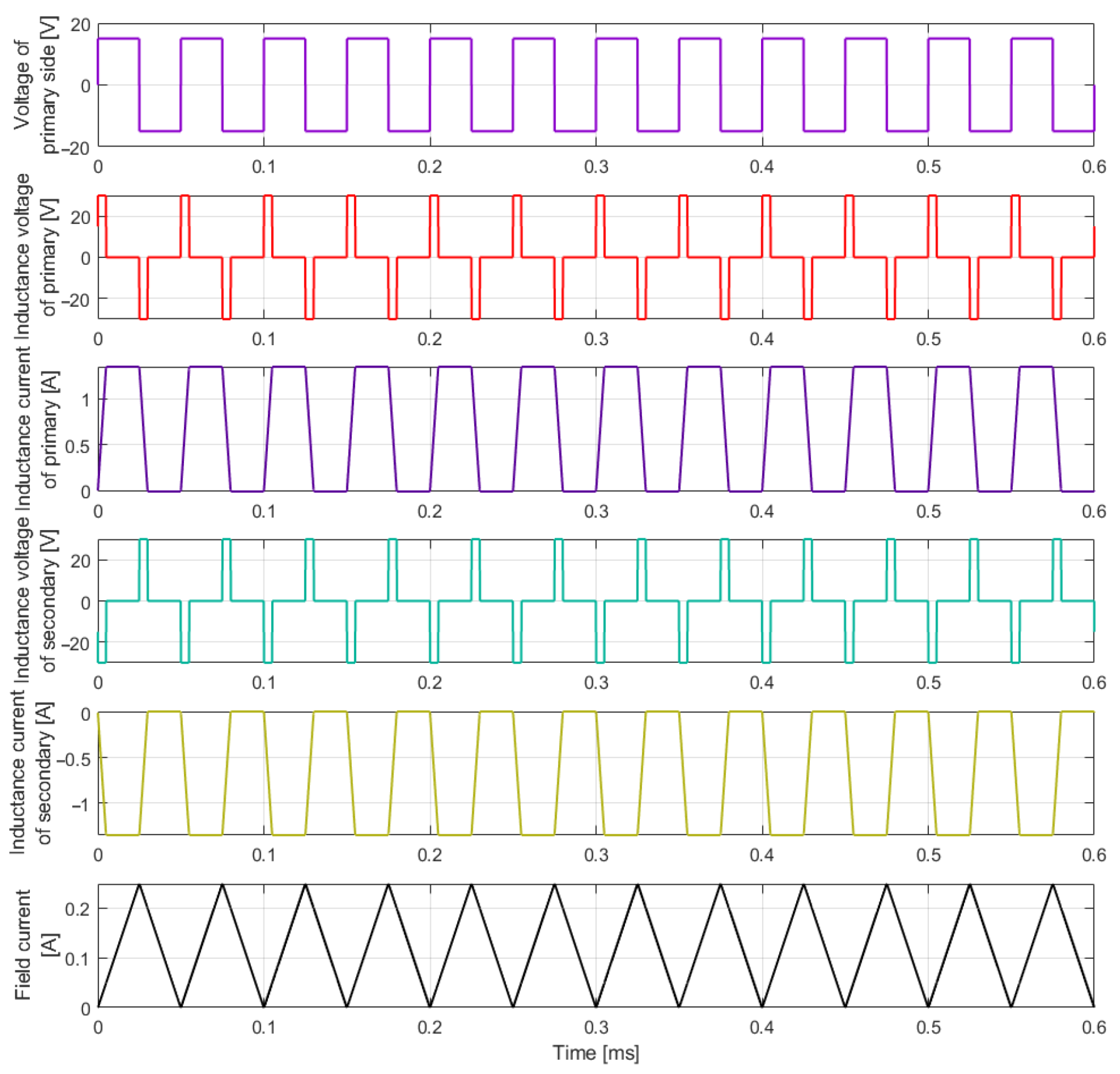
Figure 7 presents the steady-state waveforms from the time-domain simulation of the DAB converter, executed using the derived PHM. The waveforms provide a clear validation of the model’s ability to capture the fundamental energy dynamics and internal physical relationships of the converter. The quasi-square wave “Voltage of primary side” and the resulting multi-level inductance voltage act as the drivers of the system. In response, the primary and secondary inductor currents exhibit the characteristic trapezoidal shapes, with their slopes directly governed by the instantaneous inductor voltage, a behavior consistent with the PHM state equation . Crucially, the simulation also isolates the internal magnetic state, represented by the field current (magnetizing current, ). In the non-saturating regime, the model correctly predicts a pure triangular waveform, as the linear magnetic Hamiltonian () dictates. The total inductor currents are a precise superposition of this internal magnetizing current and the power-transferring current component, demonstrating the model’s structural fidelity in representing the complete set of energy-conserving and dissipative interactions that define the converter’s operation.
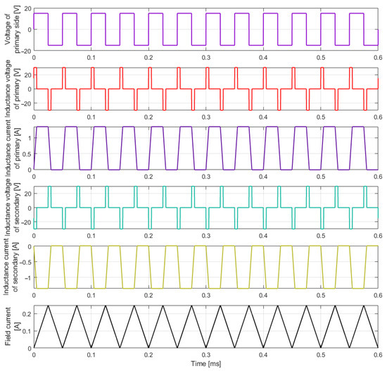
Figure 7.
Simulation results with RL loads based on PHM model.
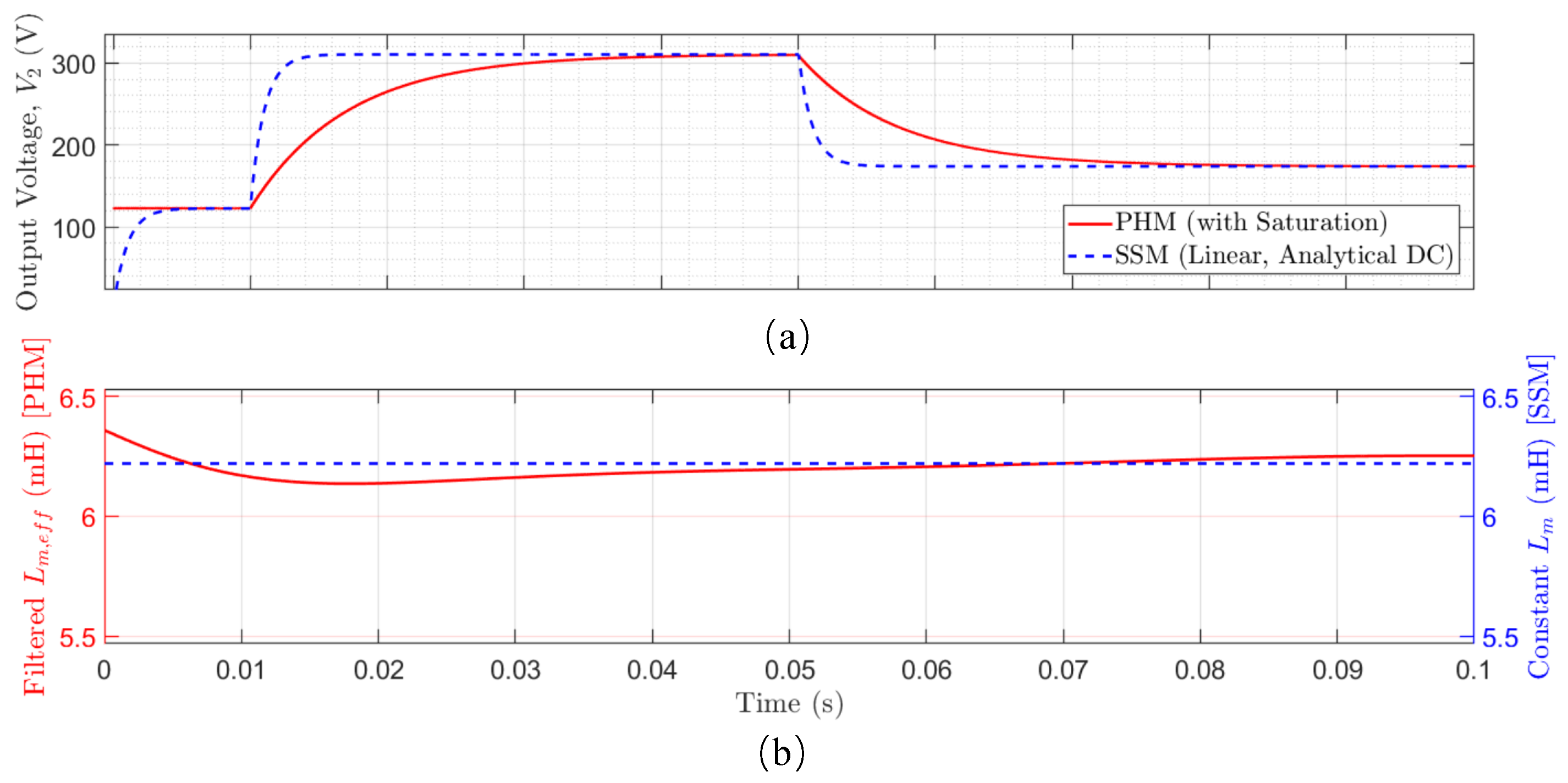
Figure 8 demonstrates the superior predictive fidelity of PHM over conventional small-signal models (SSMs) when nonlinear magnetic effects are prominent. For small-signal perturbations ( at s), the PHM and SSM trajectories show congruence, validating the local accuracy of the linearized model. However, following a large signal step at s, the SSM’s linear projection fails, while the PHM accurately predicts a gain compression in the output voltage, , as shown in Figure 8a. The deviation is physically explained by the dynamics of the effective magnetizing inductance, , shown in Figure 8b. The PHM captures the saturation-induced collapse of under high excitation, a state-dependent parameter variation that the SSM, with its constant , is structurally incapable of modeling. By preserving the system’s constitutive laws, the PHM provides an indispensable tool for analyzing and predicting the true operational limits and dynamic behavior of the DAB converter across its entire power range.
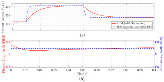
Figure 8.
PHM model compared with linear model: (a) output voltage dynamic response, (b) effective magnetizing onductance.
4.2. Experimental Results
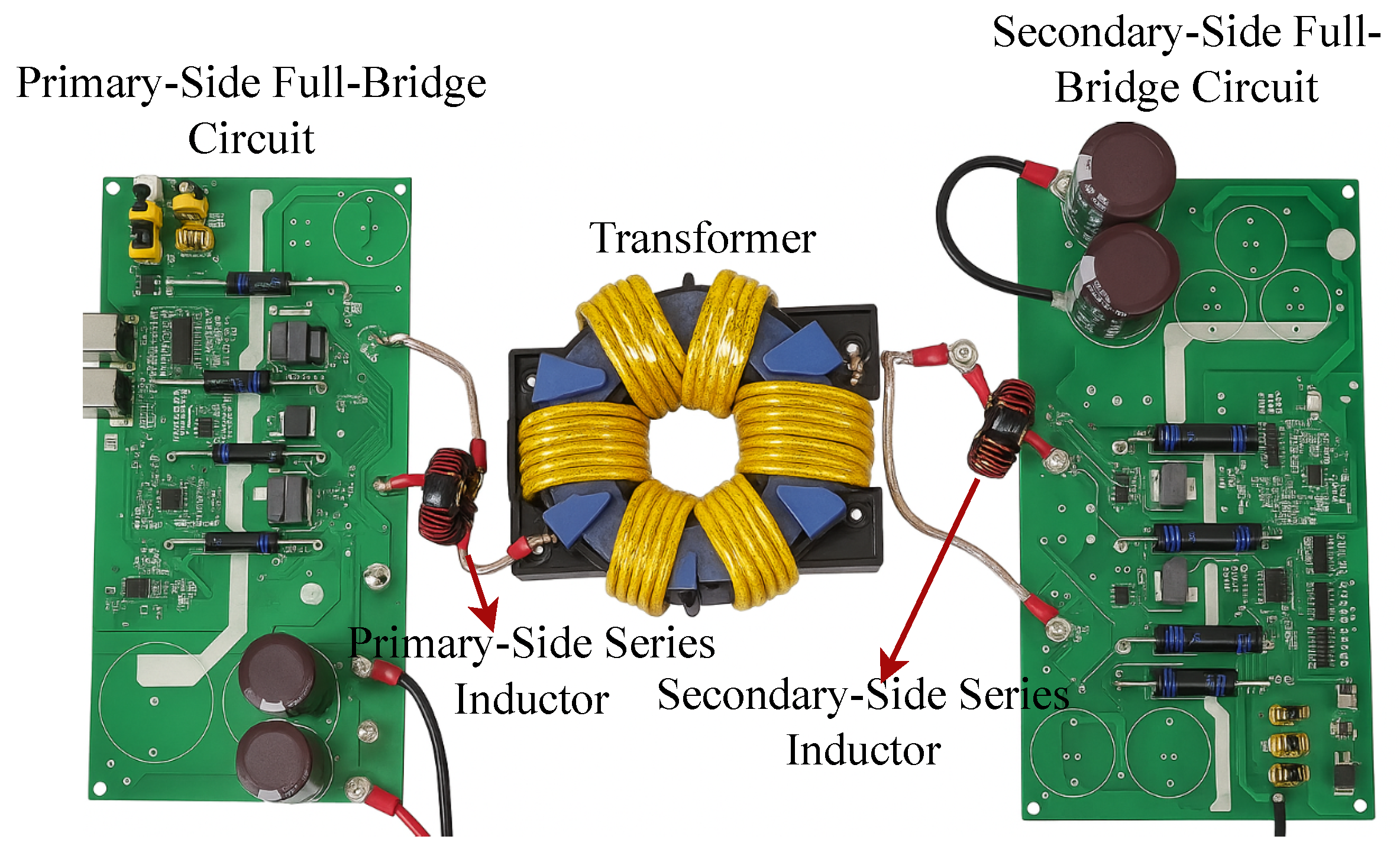
Based on the developed simulation model, a corresponding experimental platform was constructed, as illustrated in Figure 9. To ensure operational safety during testing, both the primary-side and secondary-side series inductors were implemented using air-core inductors. The experimental parameters are detailed in Table 1. The DC input was supplied by a Keysight-programmable DC power supply, and the output was connected to a DC electronic load operating in constant voltage mode to emulate a stiff DC bus. Under single-phase-shift (SPS) control at kHz, with turn ratio , rated voltage V, and phase shift , the rated output power was 25 W. Subsequently, experimental waveforms were acquired and compared with the simulated results to validate model accuracy, as shown in Figure 10 and Figure 11.
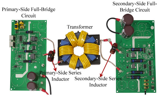
Figure 9.
DAB experimental platform.
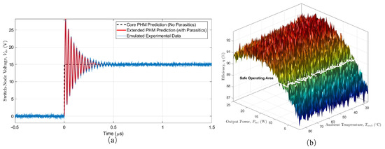
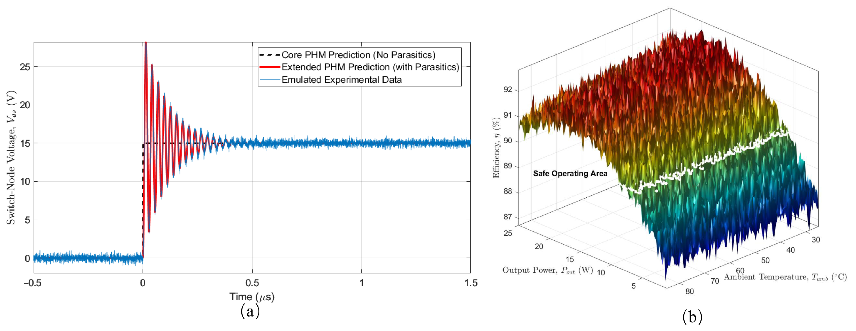
Figure 10.
(a) Dynamic step response model validation for high-frequency switching dynamics. (b) Converter efficiency under varying load and thermal conditions.
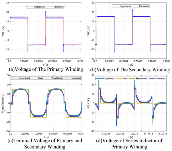
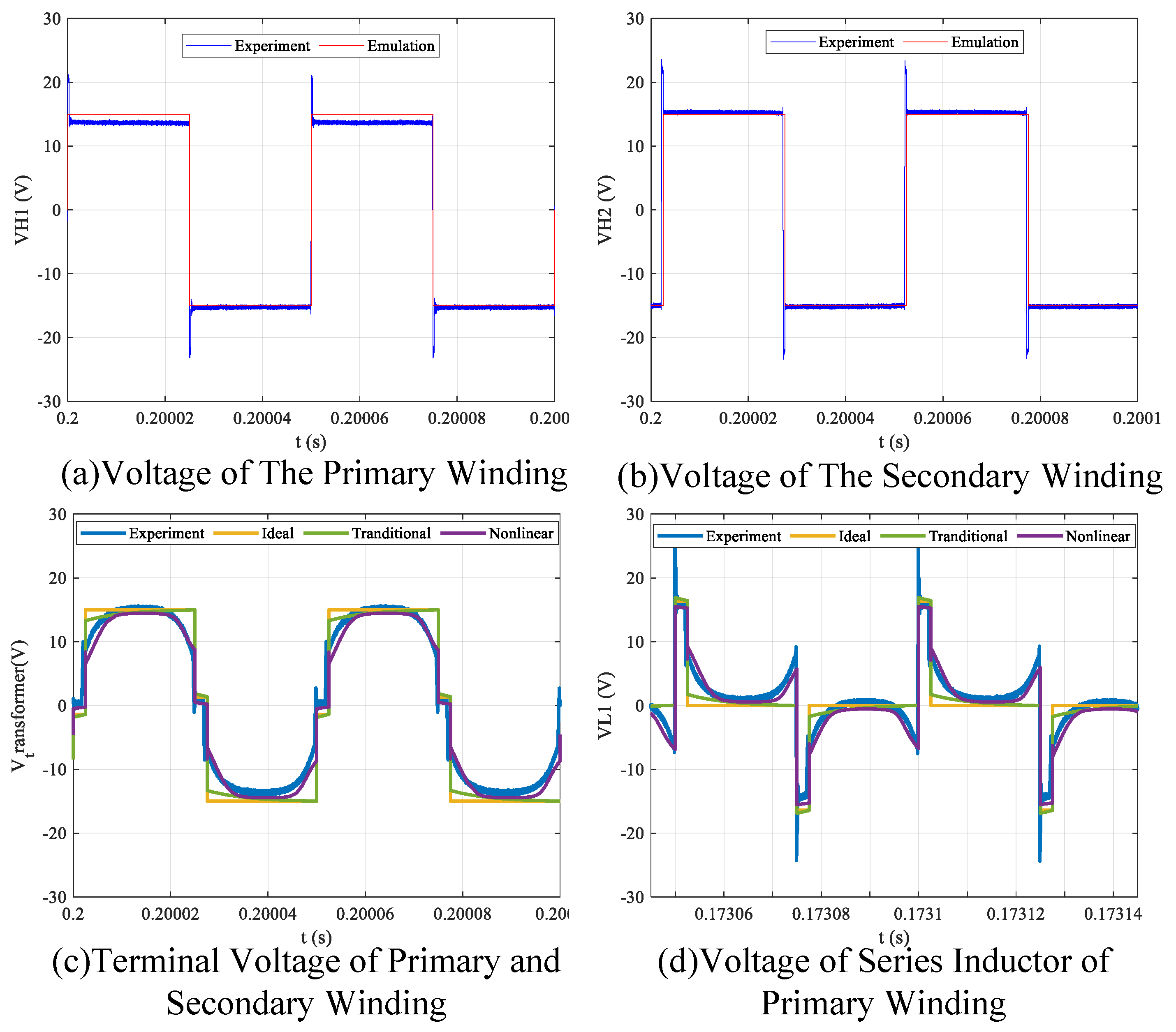
Figure 11.
Comparison of experimental and PHM model waveforms for primary side.
The experimental validation of the model’s transient-state performance is presented in Figure 10a, which examines the converter’s high-frequency switching dynamics. The emulated experimental data reveal a significant voltage overshoot and subsequent high-frequency ringing, a classic parasitic resonance phenomenon inherent to the physical hardware but absent in idealized models. Crucially, the PHM systematically augmented the parasitic energy storage elements as permitted by the framework’s structure, which achieved congruence with the measured ringing frequency, peak overshoot, and decay envelope. The result demonstrates the PHM’s robust transient predictive capability. The experimental efficiency surface in Figure 10b quantitatively demonstrates the profound impact of ambient temperature on performance. The pronounced degradation of efficiency at elevated temperatures, under high power load, provides compelling evidence for the strong thermo-electric coupling effects that are structurally captured within the model’s temperature-dependent Hamiltonian and dissipation matrices. The agreement of the PHM’s prediction with the measured high-frequency ringing—a primary source of EMI—confirms the model’s utility not only for the core multi-physics analysis but also as a theoretcial foundation for the higher-fidelity studies.
Figure 11 provides a direct comparison between measured hardware data and simulation results from different models. Figure 11a,b show the high-frequency AC voltages, and , generated by the primary and secondary full-bridges, respectively. The excellent agreement between the experimental waveforms and the emulation results confirms the accurate implementation of the switching functions and the phase-shift control that modulate the PHM interconnection matrix, . The slight ringing observed in the experimental data during voltage transitions is a high-frequency phenomenon attributable to parasitic capacitances and inductances, which, while not the primary focus of the core PHM model, can be incorporated as higher-order parasitic energy storage elements.
Figure 11c compares the measured terminal voltage of the transformer against the predictions of three distinct models. The ideal model predicts a perfect square wave, while the traditional linear model captures the fundamental shape but fails to replicate the subtle voltage drop and waveform curvature. In stark contrast, the proposed nonlinear PHM model demonstrates superior fidelity, accurately reproducing the nuanced shape of the experimental waveform. This accuracy stems from the model’s nonlinear magnetic Hamiltonian, , which correctly captures the relationship between magnetizing current and flux. This validation is further reinforced in Figure 11d, which shows the voltage across the series inductor, . In contrast, the nonlinear PHM model is uniquely capable of predicting the subtle voltage droop and nonlinear curvature of the waveform, which are direct consequences of the saturation-induced magnetizing current. This exceptional correlation for the fundamental waveform shape underscores the model’s power in capturing the essential, non-ideal, coupled dynamics that govern the converter’s core behavior.
Note that the presented PHM simulation does not capture the high-frequency voltage ringing observed during switching transitions in the experimental waveforms. The phenomenon is caused by the resonant interaction of unmodeled parasitic elements, primarily the stray inductance of the circuit layout and the output capacitance of the MOSFETs. The model was intentionally focused on the lower-frequency dynamics essential for thermal and saturation analysis to maintain clarity and tractability. However, the Port-Hamiltonian framework is inherently scalable. These parasitic effects can be systematically incorporated by augmenting the Hamiltonian with additional energy storage terms and expanding the state and interconnection matrices accordingly. Such an extension would provide a higher-fidelity model suitable for EMI studies at the expense of increased model order and computational complexity, demonstrating the trade-off between modeling scope and analytical utility. The exceptional correlation between the PHM simulation and experimental results underscores the model’s power in capturing the essential, non-ideal, coupled dynamics that govern the converter’s behavior.
5. Conclusions
This paper develops a unified Port-Hamiltonian model for a dual active bridge converter that couples electrical, magnetic, and thermal dynamics in a single energy-consistent framework. Experimental verification shows it reproduces high-frequency waveforms, including saturation-driven current spikes, more accurately than classical models. The formulation delivers efficiency and ZVS maps as well as a phase portrait that explicitly locates thermal runaway and electro-thermal Hopf boundaries, giving clear design margins. Consequently, the model provides a rigorous platform for co-designing the magnetic circuit, thermal management, and energy-based nonlinear control across the converter’s full operating range.
The economic benefits of this approach scale nonlinearly with the application’s power level. For fast EV charging, aerospace, and grid-scale energy storage, the cost of magnetic components, power modules, and thermal management is substantial. The PHM’s ability to facilitate co-design for peak efficiency and to safely reduce over-engineering margins translates directly into lower unit costs and improved operational expenditures. In these competitive industrial sectors, where reliability, power density, and efficiency are primary economic drivers, the proposed modeling paradigm offers a distinct competitive advantage by moving beyond simple prediction to enable robust, optimized, and economically viable system design.
Author Contributions
Conceptualization, Y.W. and J.A.; methodology, Y.W., P.L., and J.A.; software, P.L.; validation, J.A. and C.W.; formal analysis, Y.W. and J.A.; investigation, Y.W. and Z.S. (Zhaolong Sun); resources, F.D.; data curation, Y.W.; writing—original draft, Y.W.; writing—review and editing, J.A., C.W., and Z.S. (Zhaolong Sun); visualization, P.L.; supervision, J.A. and Z.S. (Zhan Shen); project administration, J.A.; funding acquisition, F.D. All authors have read and agreed to the published version of this manuscript.
Funding
This work was supported in part by the National Key Research and Development Program of China under grant 2022YFE0196300, the National Natural Science Foundations of China under grant number 52207191, the National Key Research and Development Program of China under grant 2024YFB4206900, 2024YFB4206901, and the Science, Technology & Innovation Funding Authority (STDF) under grant 46505.
Data Availability Statement
The original contributions presented in this study are included in this article. Further inquiries can be directed to the corresponding author.
Conflicts of Interest
The authors declare no conflicts of interest.
References
- Krismer, F.; Kolar, J.W. Efficiency-Optimized High-Current Dual Active Bridge Converter for Automotive Applications. IEEE Trans. Ind. Electron. 2012, 59, 2745–2760. [Google Scholar] [CrossRef]
- Kisacikoglu, M.C.; Ozpineci, B.; Tolbert, L.M. Examination of a PHEV charging station based on a series resonant converter. In Proceedings of the 2010 Twenty-Fifth Annual IEEE Applied Power Electronics Conference and Exposition (APEC), Palm Springs, CA, USA, 21–25 February 2010; pp. 448–455. [Google Scholar]
- Polat, H.; Hosseinabadi, F.; Hasan, M.M.; Chakraborty, S.; Geury, T.; El Baghdadi, M.; Wilkins, S.; Hegazy, O. A review of DC fast chargers with BESS for electric vehicles: Topology, battery, reliability oriented control and cooling perspectives. Batteries 2023, 9, 121. [Google Scholar] [CrossRef]
- Muhammetoglu, B.; Jamil, M. Dual Active Bridge Converter with Interleaved and Parallel Operation for Electric Vehicle Charging. Energies 2024, 17, 4258. [Google Scholar] [CrossRef]
- Huang, A.Q.; Baran, M.E.; Bhattacharya, S.; Divan, D.; Kirsch, D.C.; Lai, L.-S.; Luckjiff, G.; Reda, S.M. The Future Renewable Electric Energy Delivery and Management (FREEDM) System: The Energy Internet. Proc. IEEE 2011, 99, 133–148. [Google Scholar] [CrossRef]
- Koohi, P.; Watson, A.J.; Clare, J.C.; Soeiro, T.B.; Wheeler, P.W. A survey on multi-active bridge DC–DC converters: Power flow decoupling techniques, applications, and challenges. Energies 2023, 16, 5927. [Google Scholar] [CrossRef]
- Wang, P.; Chen, X.; Tong, C.; Jia, P.; Wen, C. Large- and small-signal average-value modeling of dual-active-bridge DC–DC converter with triple-phase-shift control. IEEE Trans. Power Electron. 2021, 36, 9237–9250. [Google Scholar] [CrossRef]
- Shao, S.; Chen, L.; Shan, Z.; Gao, F.; Chen, H.; Sha, D.; Dragičević, T. Modeling and advanced control of dual-active-bridge DC–DC converters: A review. IEEE Trans. Power Electron. 2021, 37, 1524–1547. [Google Scholar] [CrossRef]
- Takagi, K.; Fujita, H. Dynamic control and performance of a dual-active-bridge DC–DC converter. IEEE Trans. Power Electron. 2017, 33, 7858–7866. [Google Scholar] [CrossRef]
- Dey, P.; Paul, S.; Basu, K. Analytical Closed-form ZVS Boundaries of Triple-Phase-Shift Modulated Dual Active Bridge Converter. IEEE Trans. Power Electron. 2025, 40, 16870–16893. [Google Scholar] [CrossRef]
- Li, X.; Wu, F.; Yang, G.; Liu, H. Improved modulation strategy for single-phase isolated quasi-single-stage AC–DC converter to improve current characteristics. IEEE Trans. Power Electron. 2019, 35, 4296–4308. [Google Scholar] [CrossRef]
- Shen, X.; Zuo, Y.; Kong, J.; Martinez, W. Artificial intelligence applications in high-frequency magnetic components design for power electronics systems: An overview. IEEE Trans. Power Electron. 2024, 39, 8478–8496. [Google Scholar] [CrossRef]
- Bakri, R.; Corgne, G.; Margueron, X. Thermal modeling of planar magnetics: Fundamentals, review and key points. IEEE Access 2023, 11, 41654–41679. [Google Scholar] [CrossRef]
- Wang, Z.; Bak, C.L.; Wang, H.; Sørensen, H.; da Silva, F.F. Multiphysics digital model of the high frequency transformer for power electronics application considering electro-thermal interactions. IEEE Trans. Power Electron. 2023, 38, 14345–14359. [Google Scholar] [CrossRef]
- Wang, Z.; Cao, H.; Zhao, Y. Electro-Thermal Co-Design for ANPC-DAB Converter with Triple-Phase-Shift Modulation Strategy. In Proceedings of the 2024 IEEE Energy Conversion Congress and Exposition (ECCE), Phoenix, AZ, USA, 20–24 October 2024; pp. 300–305. [Google Scholar]
- Vellvehi, M.; Jordà, X.; Godignon, P.; Ferrer, C.; Millán, J. Coupled electro-thermal simulation of a DC/DC converter. Microelectron. Reliab. 2007, 47, 2114–2121. [Google Scholar]
- Wang, Y.; Mo, L.; Jiang, C.Q.; Guo, W.; Wang, X.; Chau, K.T. Temperature-Dependent Magnetic Characteristics and Thermal Runaway Assessment in Passive-Cooled Inductive Power Transfer Systems. Energy 2025, 332, 137173. [Google Scholar] [CrossRef]
- Di Bernardo, M.; Garefalo, F.; Glielmo, L.; Vasca, F. Switchings, bifurcations, and chaos in DC/DC converters. IEEE Trans. Circuits Syst. I: Fundam. Theory Appl. 1998, 45, 133–141. [Google Scholar] [CrossRef]
- Xiao, Z.; Lei, W.; Gao, G.; Wang, H.; Mu, W. Simplified discrete-time modeling for convenient stability prediction of DAB converter in energy storage system. IEEE Trans. Power Electron. 2024, 39, 12636–12651. [Google Scholar] [CrossRef]
- Li, J.; Zhao, Y.; Wu, X.; Zhang, Y.; Wang, J. Passivity-based control of dual active bridge converter in constant power load condition. Energies 2022, 15, 6685. [Google Scholar] [CrossRef]
- Mehrmann, V.; Unger, B. Control of port-Hamiltonian differential-algebraic systems and applications. Acta Numer. 2023, 32, 395–515. [Google Scholar] [CrossRef]
- Liu, Z.; Geng, Z.; Wu, S.; Hu, X.; Zhang, Z. A passivity-based control of Euler–Lagrange model for suppressing voltage low-frequency oscillation in high-speed railway. IEEE Trans. Ind. Informat. 2019, 15, 5551–5560. [Google Scholar] [CrossRef]
- Sakata, N.; Fujimoto, K.; Maruta, I. Passivity-based sliding mode control for mechanical port-Hamiltonian systems. IEEE Trans. Autom. Control 2024, 69, 5605–5612. [Google Scholar]
- Fujimoto, K.; Sakata, N.; Maruta, I.; Ferguson, J. A passivity based sliding mode controller for simple port-Hamiltonian systems. IEEE Control Syst. Lett. 2020, 5, 839–844. [Google Scholar] [CrossRef]
- Zhang, W.; Wang, W.; Wu, W. Port-controlled Hamiltonian and energy-shaping based current control scheme for grid-connected inverter. In Proceedings of the IECON 2019—45th Annual Conference of the IEEE Industrial Electronics Society, Lisbon, Portugal, 14–17 October 2019; Volume 1, pp. 6507–6512. [Google Scholar]
Disclaimer/Publisher’s Note: The statements, opinions and data contained in all publications are solely those of the individual author(s) and contributor(s) and not of MDPI and/or the editor(s). MDPI and/or the editor(s) disclaim responsibility for any injury to people or property resulting from any ideas, methods, instructions or products referred to in the content. |
© 2025 by the authors. Licensee MDPI, Basel, Switzerland. This article is an open access article distributed under the terms and conditions of the Creative Commons Attribution (CC BY) license (https://creativecommons.org/licenses/by/4.0/).

