Article

Study on Numerical Simulation of Blast Furnace Injection of Low-Rank Coal by Hydrothermal Carbonization

by
Yu Zeng
1,
Nan Zhang
2,
Andrey Karasev
3,
Xiaojun Ning
1,*,
Guangwei Wang
1,*,
Jianliang Zhang
1 and
Chuan Wang
3
1
State Key Laboratory of Advanced Metallurgy, University of Science and Technology Beijing, Beijing 100083, China
2
Henan Iron and Steel Group, Henan Advanced Steel Materials Industry Research Institute, Zhengzhou 450046, China
3
Material Science and Engineering, KTH Royal Institute of Technology, SE-100 44 Stockholm, Sweden
*
Authors to whom correspondence should be addressed.
Energies 2025, 18(19), 5141; https://doi.org/10.3390/en18195141 (registering DOI)
Submission received: 13 August 2025 / Revised: 5 September 2025 / Accepted: 24 September 2025 / Published: 27 September 2025
(This article belongs to the Section I1: Fuel)

Abstract

This study carried out a detailed investigation into the potential application of hydrothermally treated bituminous coal (hydrochar) as an injectant in blast furnace (BF) ironmaking. A tuyere model was constructed through simulation methods, and the influence of hydrochar injection on the thermal conditions within the BF hearth was also thoroughly analyzed. The results show that the gas flow velocity at the lower part of the tuyere of hydrochar injection increases, and the residual carbon mass fraction of the tuyere decreases. As the oxygen-enriched concentration increases, the CO concentration decreases. The CO concentration in the swirl zone after hydrochar injection is the highest, reaching 43.93%. The distributions of CO and CO2 exhibit opposite tendencies. Following hydrochar injection, a marked rise in temperature is observed. At an oxygen enrichment level of 30%, the tuyere zone temperature associated with hydrochar injection peaks, surpassing 2700 K. The corresponding pulverized coal burnout rate is also the highest. Thus, the injection of hydrochar has a positive impact on the air flow and temperature field, which can effectively maintain the heat balance and is conducive to strengthening BF smelting.

1. Introduction

The steel industry has achieved tremendous development and progress in the past two decades. Steel products are also increasingly driving the construction, transportation, aerospace, machinery manufacturing and other fields [1,2,3,4]. However, the main problems facing the steel industry have become increasingly prominent. Energy conservation, emission reduction, cost reduction and efficiency improvement are key issues that many large steel companies must solve. In the entire steel production process, the energy consumption of the ironmaking process is 40% higher than that of the steelmaking process [5,6,7,8,9]. Therefore, controlling energy consumption and pollutant emissions in iron-making production units is an important way to achieve green production for steel enterprises [10,11,12]. China has proposed the targets of “carbon peaking” and “carbon neutrality” to push the steel industry toward stricter CO2 emission control [13,14,15,16]. This further requires the ironmaking process to reduce CO2 emissions in a reasonable way to meet environmental requirements. In the entire steel manufacturing process, up to 70% of CO2 emissions come from the blast furnace (BF) ironmaking process, including sintering [17,18,19,20,21,22], pelletizing [23,24,25,26], coking [27,28,29], pulverized coal injection [30,31] and other production processes [32]. As the ironmaking production model for the BF gradually stabilizes. The skeleton function of raw materials and coke cannot be upgraded or replaced in the short term. Studying new methods to realize the low-carbon production in BFs from the perspective of fuel injection has become a concerned topic for steel companies.
The exothermic reaction of injected fuel is the main source of BF heat. It has demonstrated favorable performance in partially substituting coke and enhancing the reduction efficiency of iron-bearing compounds within the furnace. However, the traditional BF injection fuel structure is mainly bituminous coal and anthracite. In 2023, China’s injection coal consumption reached 160 million tons. As high-quality coal resources are increasingly depleted, the development of upgrading technologies to identify alternative high-grade carbonaceous fuels for BF injection has emerged as a key research focus among scholars [33,34,35,36,37,38]. Kim et al. [39] systematically studied the feasibility of BF injection of recyclable waste plastics. It is found that when the air temperature and oxygen-enrichment level gradually increase, in order to ensure the flammability of waste plastics, higher requirements are placed on the size of plastic particles. The coal combustion performance is also influenced by the increase in the amount of waste plastic particles injected, which further limits its large-scale industrial application. Liu et al. [40] systematically summarized and elaborated on the research work on biomass injection in BF in recent years. Biomass raw materials must undergo deep processing before they can be accepted by the BF. And the carbon content, heat, grindability, safety performance, etc., of the modified biomass materials must be strictly controlled. Taking into account factors such as cost, stability and yield, biomass raw materials will have broader application potential in the next 30 to 40 years. Zhang et al. [41] systematically studied the impact of BF injection of hydrogen, BF gas, coke oven gas (COG), natural gas and other hydrogen-rich gases on BF production through simulation methods. It was found that BF gas has the best combustion situation in front of the tuyere, and the corresponding burnout rate is the highest, while natural gas has the worst burnout rate. However, due to the difficulty in controlling the cost of hydrogen-rich gas and the difficulty in preparation, its promotion and application in the field of BF ironmaking still needs development. Based on the current main research results, the most practical optimization strategy for BF injection fuel is still to find coal substitutes. Therefore, it is more feasible to upgrade widely available low-rank coal into hydrochar products, and study the feasibility of its application in BF injection.
In this study, a three-dimensional model of the BF tuyere whirling zone was established. The hydrothermal carbonization (HTC) product and anthracite are mixed and then injected into the BF. The distinctions between hydrochar injection and conventional bituminous coal injection are systematically studied through simulation methods. Its potential as an alternative fuel to bituminous coal in the field of BF injection is further discussed. Focusing on the main characteristic parameters such as the temperature field, concentration field, and velocity field in the tuyere swirl zone, the changing rules of the thermal state of the tuyere and pipeline after the injection of hydrochar were comparatively analyzed. The research results can be helpful to promote the optimization of BF injection fuel structure and the advancement of ironmaking technology.

2. Model Construction

2.1. Physical Model and Simulation Conditions

Based on the real dimensions of a large blast furnace in China, a geometric model of the tuyere raceway area was developed, covering the straight blow pipe, pulverized coal lance, tuyere and swirling area. Figure 1 shows the three-dimensional diagram of the constructed geometric model. The front section of the gray long pipe in the picture is a straight blow pipe. Oxygen-rich gas injected through the straight blow pipe interacts with the pulverized coal at the spray gun outlet, which ensures that sufficient thermal energy is available for pulverized coal combustion in the tuyere swirling region. The black thin tube on the upper part of the straight blow pipe is the spray gun. The spray gun is inserted into the straight blow pipe at an angle of 12.5°, with a 14 mm diameter. The coal powder injected by the spray gun enters straight blow pipe along with the pure nitrogen gas flow and mixes with the hot air. The second half of the long gray tube is the air outlet. The spray gun’s end intersects the air outlet centerline, located 500 mm away in a straight line. The shape of the entire wind swirl area is oval, with the calculated height and depth being 1.3 m and 1.6 m respectively. The number of meshes in the entire model is 1.2 million, and the model wall type is set to anti-slip and thermal insulation.
The main operating parameters of the BF used in the simulation are shown in Table 1. The air volume is 5190 m3/min. The wind temperature is 1200 °C. The initial oxygen concentration in the hot air is 27%. The coal ratio is 160 kg/t. The average particle size of the mixed fuel entering the furnace is controlled below 74 microns.
The fuel introduced through the tuyere is prepared by mixing bituminous coal with anthracite at a ratio of 2:3. The ratio of hydrochar, which is an alternative fuel to bituminous coal, and anthracite coal is the same as before. Table 2 presents the proximate and ultimate analysis results of bituminous coal, anthracite coal, and hydrochar. Chinese National Standards GB/T-212 and GB/T-476 were followed as the executive criteria. A fixed particle size model was used to characterize the particle size distribution of pulverized coal particles.
Four cases are set up here to discuss the impact on the tuyere whirling zone before and after hydrochar injection in the BF. The details are shown in Table 3. The anthracite ratio is the same in all cases. Taking case 1 as the benchmark, case 2 replaces bituminous coal with hydrochar to be mixed for BF injection. Case 3 is to further increase the oxygen enrichment concentration from 6% to 9% based on the current operating conditions for analyzing how increased oxygen enrichment influences the combustion process, while the injection fuel combination is the same as case 1. Case 4 increases the oxygen concentration by 9% and uses hydrochar instead of bituminous coal for BF injection.

2.2. Governing Equations

All calculation cases in this study were performed in Fluent2022R1. The results produced are post-processed in CFD-POST. Considering that the distribution of solid and gas phases is extremely uneven during the actual injection process of coal powder in the BF tuyere, the Eulerian–Lagrangian approach is adopted to characterize the dense phase injection process of pulverized coal. This method treats solid particles as discrete phases and gases as continuous phases, and describes the movement of gas flow and solid particles in front of the tuyere by constructing different phases. The k-ε model and Reynolds-averaged Navier–Stokes are used to describe the airflow movement in detail. C μ , C 1 ε , C 2 ε , σ k and σ s in the calculation model are all constants, and their values are set to 0.09, 1.44, 1.92, 1.0 and 1.3 respectively. Pulverized coal particles are idealized into spherical shapes, and the motion of particles is represented using a discrete phase model. It takes into account the relationship between velocity and particle trajectory. The particles are regarded as not reacting to each other, and the particle motion trajectories are calculated through Newtonian mechanical equations. When the pulverized coal particles are sprayed out of the nozzle and mixed with the oxygen-rich flow in the straight blow pipe, a violent heat transfer effect will occur. This is also one of the important sources of heat in front of the tuyere. At this time, three types of heat transfer will occur: convection, hidden heat and radiant energy. Among them, convective heat transfer involves the combined effects of advection and diffusion. Equations (1)–(4) are the convective heat transfer calculation formulas, while Equation (5) represents the mass-related latent heat transfer. The heat transfer that occurs in the tuyere and the swirl zone is determined by Equations (6) and (7).
m p c p d T p d t = Q c + Q m + Q γ
Q c = h i , c o n v A p ( T g T p )
h i , c o n v = k d p N u
N u = 2.0 + 0.6 R e d 1 2 P r 1 3
Q m = d m p d t H r e a c
q r = 4 π ( α n 2 σ T 4 π + E p ) + ( α + α p ) G
G = Ω = 4 π I d Ω
The calculation equations for gas phase and solid phase reactions consist of energy, mass, momentum, turbulence and composition-related information. The entire calculation process of the tuyere model is based on these equations. The specific formula is shown in Table 4.

2.3. Chemical Reactions and Model Validity

In the actual production process of a BF, pulverized coal and hot air are mixed through the tuyere and enter the swirling zone, where a violent chemical reaction occurs under high temperature conditions. This process involves the evaporation of moisture contained in the coal, the thermal decomposition of volatile matter and its rapid combustion, the burning and subsequent gasification of coal char at high temperatures, as well as the char combustion completion. These chemical reaction processes occur rapidly in a very short time, and describing them in detail is a key link to ensure the accuracy of calculation results. The specific reaction formula is shown in Table 5. The removal process of volatile matter is the first step in the thermal reaction of coal. The ultimate analysis indicates that the volatile components of coal include C, O, H, and a small amount of N and S, which usually exist in the form of inorganic salts in coal ash. The double competition method is used to describe the coal pyrolysis behavior during the calculation. Volatile components are the first to undergo combustion reactions after pyrolysis escape. To represent the intricate reactions of volatile components, the finite-rate/eddy-dissipation model is adopted. The net reaction rate is determined by choosing the minimum value of the rates computed from the Arrhenius and eddy dissipation models. At the same time, considering that the reaction of coal char and ash matter in front of the tuyere is closely related to the utilization rate of pulverized coal, a multi-surface kinetic reaction model is adopted to characterize the surface reaction of coal char and the diffusion behavior of internal gases. For the interaction between pressure and velocity, the Simple method is used to discretize the space to solve the problem. This method is based on the least squares unit to ensure speed and accuracy [41].
As simulation methods are increasingly used in the field of BF ironmaking, research focusing on the combustion performance of coal powder in front of the tuyere has been gradually reported. Relevant studies have shown that fluid mechanics methods to simulate and calculate the cold and thermal properties and reactions of coal powder in front of the tuyere are of great help in guiding BF production. Considering the factors of calculation accuracy and calculation time, a total of 1.2 million computational grids not only controls the calculation cost, but also effectively ensures the precision of the computed results. Moreover, the results under normal working conditions were compared with the industrial test results, and the relative error of the burnout rate was controlled within 3%, ensuring the credibility of the calculation results.

3. Results and Discussions

3.1. Velocity Field

Figure 2 shows the changes in the velocity field of coal powder at the tuyere raceway under different injection scenarios. From the results, it can be found that the instantaneous speed of the hot air in the straight blow pipe will decrease when it mixes with the coal-nitrogen flow at the outlet of the spray gun. This is because when ejected from the spray gun outlet, particles collide with the air flow transported by the dense phase and generate a certain resistance, resulting in a slight decrease in the instantaneous speed. But when the solid and air flow are fully mixed, the speed of the gas–solid mixture increases sharply to 300 m/s after reaching the tuyere. And it also can be seen that the velocity of the coal–air mixture in the lower tuyere region attains its maximum value. The airflow speed in the upper part of the air outlet is smaller than that in the lower part. This is mainly because the coal gun is inserted positioned at a defined angle, and the coal particle flow is more likely to accumulate in the lower part after being ejected from the gun outlet. However, the speed of the particle airflow drops sharply after entering the swirl zone through the tuyere. After the pulverized coal is mixed and preheated with oxygen in the high-temperature environment at the tuyere, the volatile matter is quickly removed. The gas produced after the high-temperature reaction diffuses in the gyration zone, resulting in a significant reduction in speed. Changes in airflow velocity show a similar trend under all case conditions. A similar situation was found in the research results of Shen et al. [42].
The velocity variations at the tuyere are depicted in Figure 3. From the figure, it is evident that the airflow velocities in Case 2 and Case 4 are higher compared to Case 1 and Case 3, indicating that the air flow velocity of coal particles has increased after injecting hydrochar. As the carbon content of hydrochar increases, the density of coal particles is enhanced, and the overall density of the air flow is also increased. When the pipeline carrying capacity is sufficient, the gas flow rate shows an increasing trend. The stronger gas flow increases the scouring effect on the pipeline, and the risk of pipeline wear also increases accordingly. Therefore, there is a certain limit to this increase in flow rate. It is worth mentioning that compared with the injection of traditional bituminous coal when injecting hydrochar, the speed of the airflow at the tuyere and the swirl zone does not change negatively. The results reveal that the pulverized coal flow rate after injection of hydrochar will not cause clogging of the coke window, ensuring stable smelting in front of the tuyere.

3.2. Particle Char Mass Distribution

Figure 4 shows the distribution trajectory of particle char. It can be observed that the amount of the particle char begins to gradually change from the exit of the coal gun to the tuyere. During this process, volatile substances in coal mainly escape. With the separation of volatile components, the mesoporous and macroporous structures of coal particles increase, creating conditions for the contact between coal powder and oxygen. After reaching the tuyere swirl zone, the particle char mass fraction decreases significantly, and the carbon in the coal mainly undergoes combustion and gasification reactions. The theoretical combustion temperature in the tuyere swirl zone can reach 2500 °C. The coal particles react rapidly in a very short time under the high temperature environment in the gyration. However, owing to the presence of an extremely high-velocity gas stream and the adhesion of coal ash on the surface of residual char particles, the contact with oxygen is seriously hindered, resulting in the inability of the coal powder to be completely burned. It can also be seen from the trajectory diagram that after the injection of hydrochar, especially under the working conditions of Case 4, the mass fraction has decreased compared with other cases. Wang et al. [43] has shown that hydrochar has stronger combustion intensity, so its injection shows better burnout performance in front of the tuyere.

3.3. Gas Mass Fraction

Figure 5 shows the concentration changes in CO and CO2 within the tuyere raceway. The CO concentration curve reveals that comparing the injection of hydrochar and bituminous coal, there is no significant difference in the concentration change when the oxygen enrichment concentration is 27%. However, when the oxygen-enriched concentration is increased to 30%, it can be seen from case 3 that the CO level at the tuyere core area is significantly less than in other working conditions. Moreover, under the same oxygen-rich conditions, the concentration of CO in the gyration zone did not decrease significantly after HTC injection. This is because the carbon content in coal increases during the hydrochar injection, and the reaction between carbon and oxygen in the swirl zone to generate carbon monoxide increases. Under high oxygen-rich conditions, a blend of bituminous and anthracite coal is always in an oxygen-rich state in the swirl zone. Therefore, after the injection of hydrochar, the reducing atmosphere in the tuyere swirl zone has not been significantly weakened, which ensures a better distribution of the initial gas flow in the Bird’s Nest zone of the hearth. Observing the CO2 concentration distribution diagram, it becomes clear that after the oxygen-enriched concentration increases, the CO2 concentration in the swirl zone increases significantly when bituminous coal and anthracite are mixed and injected. This is exactly the opposite of the change pattern of CO. For all working conditions, the mass fraction of CO is significantly higher than CO2, indicating that the injection of hydrochar instead of bituminous coal will not have an adverse effect on the distribution of reducing gases in the tuyere swirl zone. On the contrary, the utilization rate of coal powder still remains at a high level.
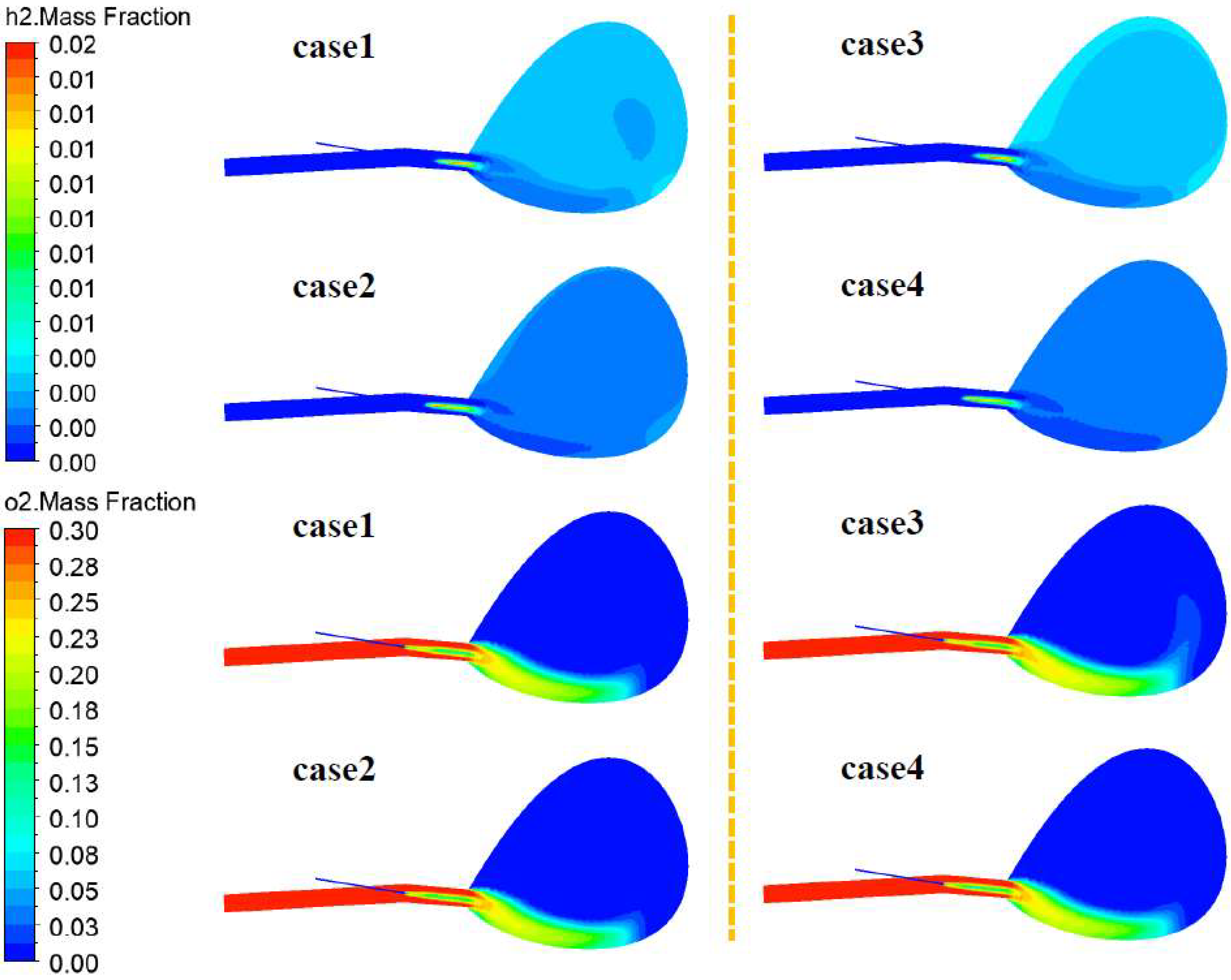
Figure 6 shows the changes in H2 and O2 mass concentrations. It is evident that the H2 concentration for the four investigated conditions is extremely low. Regardless of adopting the conventional bituminous–anthracite coal mixture for injection, or the newly proposed hydrochar–anthracite blend, the H2 concentration in the swirl zone is almost 0. From the image, the H2 concentration of working conditions 2 and 4 is lower than that of working conditions 1 and 3. Since the volatile components in the hydrochar are lower than those of bituminous coal, and the ultimate analysis results can also show that its hydrogen content is lower, this makes the reaction behavior of the hydrochar in the gyration zone less related to the hydrogen element. The O2 concentration diagram indicates that the straight blow pipe exhibits the highest O2 content. As the airflow flows into the swirling zone, the O2 content gradually decreases and participates more in the combustion and gasification reactions.
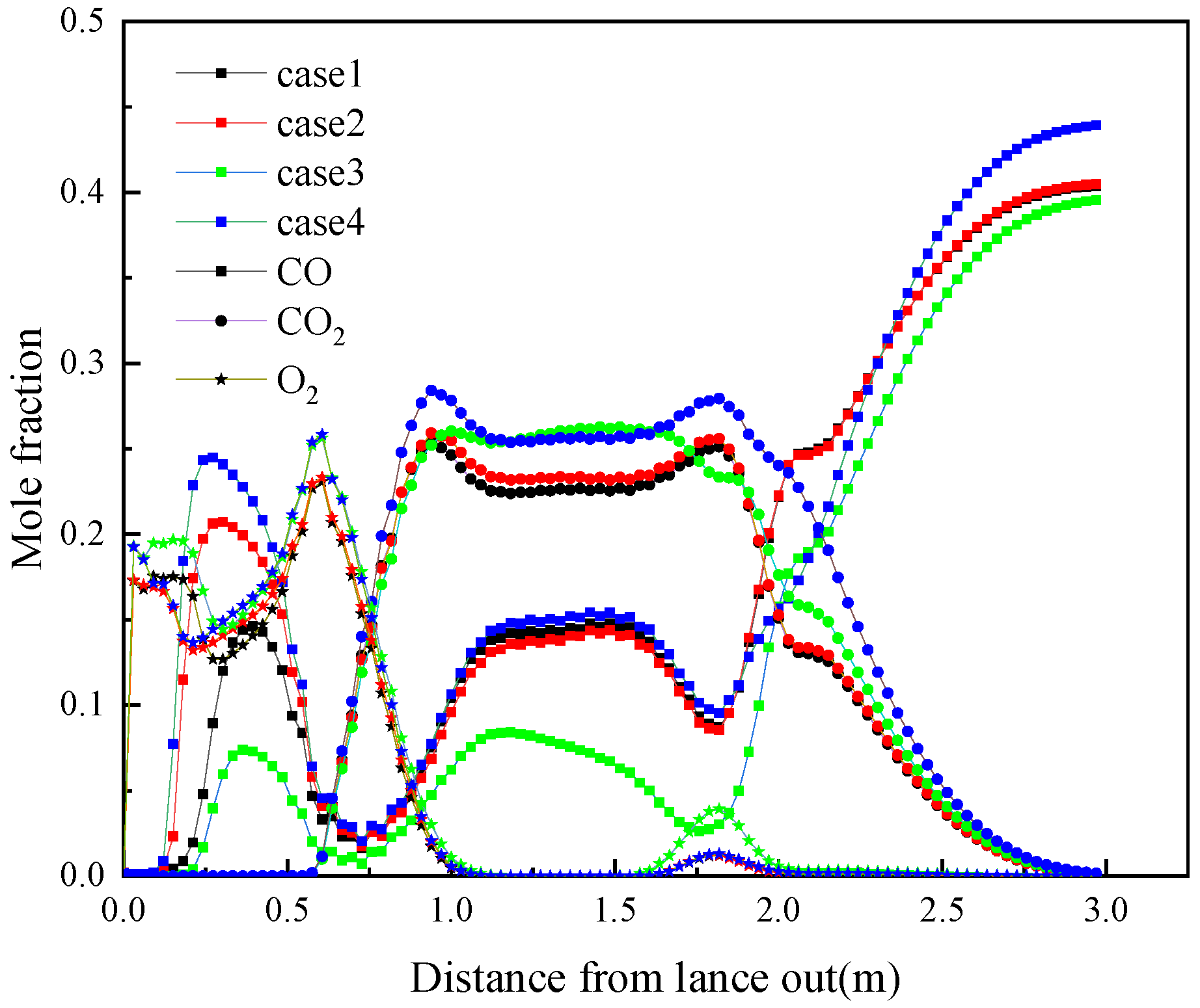
Figure 7 shows the changes in gas composition along the centerline of the tuyere. The gas at the coal gun outlet consists entirely of nitrogen, with the mole fractions of all other gases being zero at this location. The coal is rapidly mixed with the high temperature air in the straight blow pipe. Due to the increase of nitrogen, a reduction in oxygen concentration is observed near the coal gun outlet. Maximum oxygen concentration is observed 0.6 m downstream of the coal gun outlet. Refer to the aforementioned velocity field cloud map, the airflow velocity reaches the maximum value below the center line of the air outlet position, indicating that the flow of oxygen-rich hot air is smoothest at this location, forming a stable turbulent area, that is, the concentration of oxygen accumulation is the highest in this area, close to the oxygen-enriched concentration of blast air. Upon entering the tuyere, the airflow oxygen begins to engage in the combustion and gasification processes of the injected coal particles, significantly influencing the local reaction dynamics, so the concentration gradually decreases. At a position 1.05 m away from the tuyere, the oxygen concentration is 0. It can also be found that after oxygen enrichment in Cases 3 and 4, the oxygen mole fraction at the tuyere is higher than that in Cases 1 and 2, which is almost the same as the oxygen enrichment concentration of the blast. It reflects the differences in actual working conditions well. From the CO concentration change curves, it can be seen that the CO concentration appears a peak near 0.5 m from the coal gun outlet. The release of volatile matter in coal mainly occurs here. However, judging from the scatter distribution in the figure, the absolute content of this part of CO is still small, which also corresponds to the result of the CO mass distribution cloud chart. As the gas flow continues to flow, the CO concentration decreases rapidly at the 0.75 m position, and O2 dominates at this time. As the distance increases, the CO concentration begins to gradually increase. Within the range of 1 to 2 m from the coal gun outlet, the CO concentration in working condition 4 is the highest, indicating that the ability to generate reducing gas under high oxygen-rich conditions is the strongest after hydrochar injection. This is also a strong reflection of the strong gasification performance of the hydrochar. The CO concentration in working condition 3 fluctuated slightly, and its CO2 concentration was higher than other working conditions in this range, reaching 26.15%. This indicates that, while increasing the oxygen-enriched concentration under the traditional mixed injection of bituminous and anthracite coal enhances the burnout of pulverized coal, it adversely affects the control of reducing gas concentrations ahead of the tuyere. At the position close to the coke bed in the swirling zone, it can be seen that the CO content rises sharply. At a position 3 m away from the coal gun outlet, it can be clearly observed that the CO concentration produced by the injection of hydrochar is 43.93%, significantly higher than 40.41% of case 1, 40.49% of case 2 and 39.56% of case 3. This further proves the feasibility of the hydrochar to replace bituminous coal for BF injection. As for the CO2 change curve, its overall change trend is opposite to that of the CO curve.

3.4. Thermal Simulation Research

Figure 8 illustrates the temperature variations within the tuyere gyration zone. It can be seen that for all simulation results, there is an area of increased temperature close to the spray gun outlet. The pulverized coal leaves the coal gun and mixes with high-temperature hot air under the action of N2 flow. Since the temperature far exceeds the ignition point of the coal, its preheating and the removal of volatile matter occur in a very short time. Volatile matter undergoes oxidative combustion, which liberates heat and consequently generates localized high-temperature zones in the tuyere. Since the coal injection in the spray gun and the transportation of hot air in the blow pipe are both a continuous process, it can be seen that as the air flow gradually moves into the swirling area, the temperature at the outlet of the tuyere is close to the wind temperature of 1473 K. Due to the heat transfer effect between part of the unburned pulverized coal and the high-temperature hot air during the dense-phase transportation process, the temperature field in this area will also decrease. As the coal gas flow enters the tuyere swirl zone, the carbon in the coal and the oxygen in the hot air combine to generate a large amount of CO or CO2. This process is an exothermic reaction, which is also the most important source of heat in the BF. After the coal gas flow enters the tuyere swirl zone, due to the continuous input of oxygen-rich hot air, the endothermic reaction of carbon occurs in a low proportion. The tuyere whirlpool area is in a carbon-rich state due to the dense distribution of coke beds. The temperature of the entire tuyere swirl zone continues to increase as the pulverized coal disperses and the combustion reaction continues. The center temperature of the tuyere swirl zone of all working conditions exceeded 2700 K. Zhang et al. [41] reports that when the coal ratio is 170 kg/t, the maximum temperature of the raceway is close to 2800 K, but too high a raceway temperature will lead to unstable thermal state of the furnace, so it can be adjusted by controlling the oxygen enrichment rate and wind temperature. After the injection of hydrochar, compared with case 1, the central area of the gyration zone in case 2 shows a higher temperature. Under high oxygen-rich conditions, the overall temperature of the tuyere swirl zone in case 3 is lower than that in case 4, suggesting that hydrochar injection enhances combustion performance in front of the tuyere.
Figure 9 shows the numerical changes in the temperature field on the tuyere center line. It can be seen from the results that with increasing distance from the coal gun outlet, the temperatures under the four different working conditions exhibit a trend of initial increase, followed by a decrease, and then a subsequent rise. The temperature along the centerline of the tuyere attains its peak at 0.25 m from the coal gun outlet, but as the airflow moves forward, the temperature gradually decreases. As mentioned before, this peak temperature is mainly related to the release of volatiles and rapid combustion reactions. At a distance of 0.75 m from the exit of the coal gun, the temperature begins to gradually increase, and reaches the peak at the swirl zone entrance. At this time, residual carbon reacts vigorously through combustion and gasification, which will provide more heat to the rising gas flow. A comparison of the simulation results under different working conditions reveals that the temperature in the tuyere swirl zone of working conditions 2 and 4 is significantly higher than that of working conditions 1 and 3, indicating that the heat generated from the combustion of the mixed fuel of hydrochar is more complete in the tuyere. The heat in the central and lower regions of the furnace is thus increased, and the activity and stability of the furnace are effectively guaranteed, which is conducive to the gas flow providing more heat to participate in indirect reduction during the rising process, and promoting the reduction efficiency of iron ore. Therefore, the injection of hydrochar can provide more heat to the tuyere whirling zone without affecting the forward movement of the BF, creating conditions for the BF to increase the smelting intensity.
Figure 10 shows the temperature variations in the tuyere swirl zone. The results indicate that, at the same position within the swirl zone, the temperature after injecting hydrochar is higher than that observed with bituminous coal. At a position closer to the coal gun, the volatile matter in the coal quickly escapes and burns after the coal and hot air are mixed, and the exothermic reaction expands the high-temperature region. When the coal gas continues to flow, the coal particles and oxygen are fully mixed, and due to the escape of volatile matter, the coal particles exhibit an increased surface area, facilitating more complete contact with oxygen. The pulverized coal entering the swirling zone undergoes a violent explosion reaction. This process releases more heat, causing the temperature in the tuyere to rise sharply. Thus, the heat supply of the temperature field in the whirling zone after the injection of hydrochar is still maintained in a balanced state, and the thermal behavior characteristics meet the requirements of BF injection.
The burnout rate of the coal serves as a key parameter for assessing the thermal conditions in the blast furnace tuyere. A higher burnout rate indicates a more effective substitution of coke with coal. In this study, the burnout rate is determined using the ash balance approach. The calculation formula is as Equation (8).
Burnout = ( 1 m a , 0 m a ) / ( 1 m a , 0 )
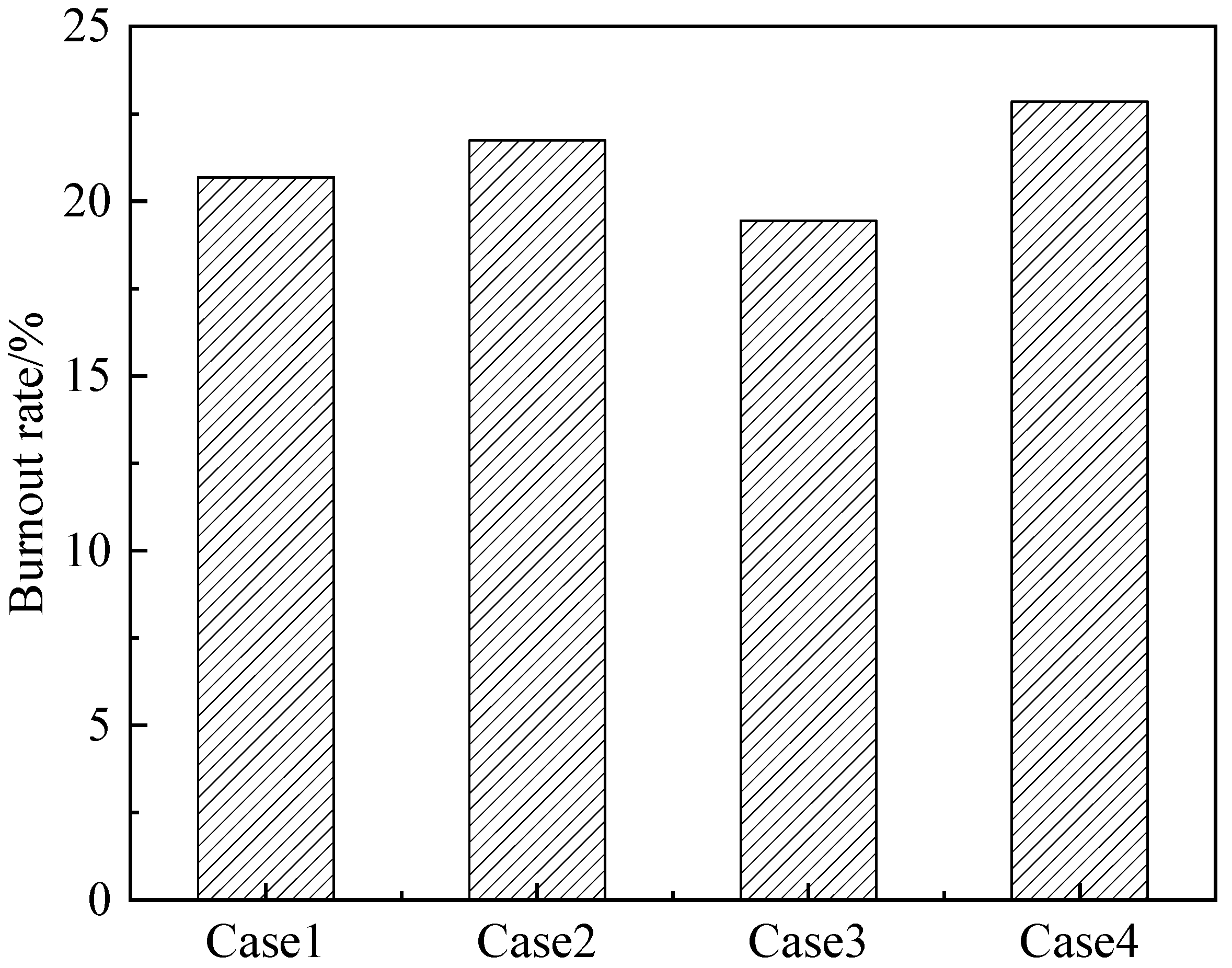
The burnout rate of pulverized coal at the outlet of the direct blowing pipe under different working conditions is shown in Figure 11. It can be seen from the figure that the burnout degree of the coal powder at the direct blowing pipe outlet under the condition of conventional bituminous coal and anthracite mixed injection is 20.69%. When bituminous coal is replaced by hydrochar, the coal burnout degree at the same position reaches 21.74%, which indicates that hydrochar can release more heat in the tuyere whirlpool area and the mixed fuel combustion becomes more complete. Following an increase in the oxygen enrichment rate from 27% to 30%, the burnout value of the bituminous coal–anthracite mixture stays around 20%, while the burnout rate of hydrochar mixed fuel increases to 22.85%, indicating that higher oxygen enrichment is conducive to the release of hydrochar combustion performance. Considering the higher the cost of higher oxygen enrichment under actual working conditions, and the influence of high oxygen enrichment on furnace temperature and coal gas flow, the oxygen enrichment rate should be controlled below 30% when hydrochar injection is applied.
Figure 12 shows the change pattern of volatile matter on the tuyere center line. It can be seen that with increasing distance from the coal gun outlet, the release position of volatile matter in the pulverized coal does not change significantly before and after the hydrochar injection. The volatile matter release content reaches the maximum value at a position 0.12 m away from the coal gun outlet. However, as the carbonaceous combustion reaction proceeds in front of the tuyere, the volatile matter has completely reacted within a range of 0.375 m away from the coal gun outlet. By comparing the results of different conditions, it is observed that the volatile substances in Case 2 and Case 4 have reacted completely before 0.25 m from the coal gun outlet. However, the volatile reaction in Cases 1 and 3 lags significantly behind. From the image, what can also be intuitively found is that the reaction rate of volatile matter of the hydrochar in the tuyere and swirl zone is higher than that of bituminous coal. The earlier the volatile matter reacts, the more conducive it is to the burning of remaining carbon particles, and the combustion process of volatile matter is an exothermic process, which can also provide more heat to the tuyere to make the pulverized coal burn more fully. Therefore, the injection of hydrochar is more conducive to maintaining the heat balance in the tuyere swirl zone.

4. Conclusions

By constructing a three-dimensional geometric model of the tuyere zone of the actual BF, the difference between the hydrochar and the traditional bituminous coal/anthracite injection was studied in detail. The main conclusions obtained are shown below.
(1) After fuel injection, the gas stream velocity in the tuyere’s lower region increases, and the gas flow velocity at the bottom of the swirl zone is relatively high. The proportion of unreacted carbon within the tuyere swirl zone decreases after the hydrochar injection. At an oxygen enrichment level of 30%, the residual carbon mass fraction decreases compared with the case of bituminous coal injection. CO and CO2 concentration distributions show opposite trends. As oxygen enrichment increased, a decline in CO concentration was observed, and the CO concentration in the swirling zone after the hydrochar injection was the highest, reaching 43.93%.
(2) For the four injection conditions, the temperature of the swirl zone can ensure sufficient heat supply. The temperature in the gyration zone increased significantly after the injection of hydrochar. With oxygen enrichment elevated to 30%, the temperature in the gyration zone corresponding to the hydrochar injection reaches the maximum value, and the maximum centerline temperature exceeds 2700 K.
(3) The injection of hydrochar has a positive impact on the air flow field and temperature field of the tuyere. It is proved that the use of hydrochar for BF injection can effectively ensure the heat supply within the bird’s nest zone of the tuyere, which is beneficial to the strengthening of BF smelting.

Author Contributions

Y.Z.: Writing—original draft preparation; N.Z.: Writing—original draft preparation; X.N.: Formal analysis, Funding acquisition, Writing-review and editing; G.W.: Funding acquisition and supervision, Methodology and supervision; A.K.: Writing—review and editing; J.Z.: Writing—review and editing; C.W.: Writing—review and editing. All authors have read and agreed to the published version of the manuscript.

Funding

This research was funded by the National Natural Science Foundation of China, grant number 52174295, and by the China Baowu Low Carbon Metallurgy Innovation Foundation, grant numbers BWLCF202215 and BWLCF202305.

Data Availability Statement

The original contributions presented in this study are included in the article. Further inquiries can be directed to the corresponding author.

Acknowledgments

All authors gratefully acknowledge the financial support from the National Natural Science Foundation of China (No. 52174295) and the China Baowu Low Carbon Metallurgy Innovation Foundation (BWLCF202215 and BWLCF202305).

Conflicts of Interest

The authors declare no conflicts of interest.

Nomenclature

AbbreviationParaphrase
HTCHydrothermal carbonization
C μ Constants in turbulence models
C 1 ε Constants in turbulence models
C 2 ε Constants in turbulence models
σ k Constants in turbulence models
σ s Constants in turbulence models
α Absorption coefficient
H r e a c Heat in the reaction (J/kg)
A p particle surface area (m2)
C D Coefficient of resistance
C P Particles specific heat (J/(g·K))
E p Particle equivalent radiation
f D Drag force of particle (N)
G Incident radiation
H Enthalpy (J/kg)
I Radiation intensity (W/m2)
m · Mass transfer rate (kg/s)
k Kinetic energy of the turbulent (m2/s2)
N The number of particles
n Medium refractive index
n p The number of per unit volume particle (m3)
P Particle
p pressure (Pa)
q r Radiation heat flux
q Particle heat transfer (W)
p k Turbulence caused by viscous forces
T g The temperature of gas (K)
T P The temperature of the particle (K)
U P The velocity of the particle (m/s)
U The velocity of the gas (m/s)
W i The reaction rate of i (kg/(m3·s))
Y i The mass fraction of i
ρ Density (kg/m3)
μ Turbulent viscosity
σ B The constant that represents Stefan-Boltzmann
σ k The constant in turbulence model
λ Thermal conductivity (W/(m·K))
Γ i molecular diffusivity of i
ε The rate of turbulent dissipation (m2/s3)
ε p Coal emissivity

References

  1. Nechifor, V.; Calzadilla, A.; Bleischwitz, R.; Winning, M.; Tian, X.; Usubiaga, A. Steel in a circular economy: Global implications of a green shift in China. World Dev. 2020, 127, 104775. [Google Scholar] [CrossRef]
  2. Fan, Z.Y.; Friedmann, S.J. Low-carbon production of iron and steel: Technology options, economic assessment, and policy. Joule 2021, 5, 829–862. [Google Scholar] [CrossRef]
  3. Mele, M.; Magazzino, C. A machine learning analysis of the relationship among iron and steel industries, air pollution, and economic growth in China. J. Clean. Prod. 2020, 277, 123293. [Google Scholar] [CrossRef]
  4. Manzolini, G.; Giuffrida, A.; Cobden, P.D.; Van Dijk, H.A.J.; Ruggeri, F.; Consonni, F. Techno-economic assessment of SEWGS technology when applied to integrated steel-plant for CO2 emission mitigation. Int. J. Greenh. Gas Control 2020, 94, 102935. [Google Scholar] [CrossRef]
  5. Na, H.M.; Sun, J.C.; Qiu, Z.Y.; Yuan, Y.X.; Du, T. Optimization of energy efficiency, energy consumption and CO2 emission in typical iron and steel manufacturing process. Energy 2022, 257, 124822. [Google Scholar] [CrossRef]
  6. Sun, G.Y.; Li, B.; Guo, H.J.; Yang, W.S.; Li, S.Y.; Guo, J. Thermodynamic Study of energy consumption and carbon dioxide emission in ironmaking process of the reduction of iron oxides by carbon. Energies 2021, 14, 1999. [Google Scholar] [CrossRef]
  7. Na, H.M.; Sun, J.C.; Qiu, Z.Y.; He, J.F.; Yuan, Y.X.; Yan, T.Y.; Du, T. A novel evaluation method for energy efficiency of process industry—A case study of typical iron and steel manufacturing process. Energy 2021, 233, 121081. [Google Scholar] [CrossRef]
  8. Hu, Y.C.; Rufford, T.E.; Chen, J.; Hao, L.Y.; Li, M.R.; Qiu, Y.X.; Garg, S.; Rudolph, V.; Wang, G. Opportunities to reduce energy consumption and CO2 emissions from ironmaking blast furnace using CO2 electrolysis to CO for carbon recycling. J. Clean. Prod. 2023, 389, 135997. [Google Scholar] [CrossRef]
  9. Ma, K.H.; Deng, J.Y.; Wang, G.; Zhou, Q.; Xu, J. Utilization and impacts of hydrogen in the ironmaking processes: A review from lab-scale basics to industrial practices. Int. J. Hydrogen Energy 2021, 46, 26646–26664. [Google Scholar] [CrossRef]
  10. Zhang, N.; Zhang, J.L.; Wang, G.W.; Ning, X.J.; Meng, F.Y.; Li, C.H.; Ye, L.; Wang, C. Physicochemical characteristics of three-phase products of low-rank coal by hydrothermal carbonization: Experimental research and quantum chemical calculation. Energy 2022, 261, 125347. [Google Scholar] [CrossRef]
  11. Wang, Y.J.; Zuo, H.B.; Zhao, J. Recent progress and development of ironmaking in China as of 2019: An overview. Ironmak. Steelmak. 2020, 47, 640–649. [Google Scholar] [CrossRef]
  12. Li, J.; Kuang, S.B.; Jiao, L.L.; Liu, L.L.; Zou, R.P.; Yu, A.B. Numerical modeling and analysis of hydrogen blast furnace ironmaking process. Fuel 2022, 323, 124368. [Google Scholar] [CrossRef]
  13. Wang, Y.; Guo, C.H.; Chen, X.J.; Jia, L.Q.; Guo, X.N.; Chen, R.S.; Zhang, M.S.; Chen, Z.Y.; Wang, H.D. Carbon peak and carbon neutrality in China: Goals, implementation path and prospects. China Geol. 2021, 4, 720–746. [Google Scholar] [CrossRef]
  14. Zhao, X.; Ma, X.W.; Chen, B.Y.; Shang, Y.P.; Song, M.L. Challenges toward carbon neutrality in China: Strategies and countermeasures. Resour. Conserv. Recycl. 2022, 176, 105959. [Google Scholar] [CrossRef]
  15. Yang, P.J.; Peng, S.A.; Benani, N.; Dong, L.Y.; Li, X.M.; Liu, R.P.; Mao, G.Z. An integrated evaluation on China’s provincial carbon peak and carbon neutrality. J. Clean. Prod. 2022, 377, 134497. [Google Scholar] [CrossRef]
  16. Wei, Y.M.; Chen, K.Y.; Kang, J.N.; Chen, W.M.; Wang, X.Y.; Zhang, X.Y. Policy and management of carbon peaking and carbon neutrality: A literature review. Engineering 2022, 14, 52–63. [Google Scholar] [CrossRef]
  17. Li, J.Q.; Li, C.Z.; Zhang, W.; Zhang, J.H.; Xue, Z.L. Material, energy and exergy flows of the oxygen blast furnace process with sintering flue gas injection. J. Clean. Prod. 2022, 371, 133294. [Google Scholar] [CrossRef]
  18. Gavel, D.J.; Adema, A.; van der Stel, J.; Peeters, T.; Sietsma, J.; Boom, R.; Yang, Y.X. A comparative study of pellets, sinter and mixed ferrous burden behaviour under simulated blast furnace conditions. Ironmak. Steelmak. 2021, 48, 359–369. [Google Scholar] [CrossRef]
  19. Luukkonen, T.; Olsen, E.; Turkki, A.; Muurinen, E. Ceramic-like membranes without sintering via alkali activation of metakaolin, blast furnace slag, or their mixture: Characterization and cation-exchange properties. Ceram. Int. 2023, 49, 10645–10651. [Google Scholar] [CrossRef]
  20. Xiao, L.Y.; Wang, Y.; Li, W.Y.; Zhang, Q.; Yue, Y.; Qian, G.R. Double high-value utilization of valuable resources in the process of co-sintering detoxification of high chlorine incineration fly ash and blast furnace dust. Resour. Conserv. Recycl. 2024, 204, 107506. [Google Scholar] [CrossRef]
  21. Du, Y.; Gao, J.T.; Lan, X.; Guo, Z.C. Preparation of TiC ceramics from hot Ti-bearing blast furnace slag: Carbothermal reduction, supergravity separation and spark plasma sintering. J. Eur. Ceram. Soc. 2022, 42, 2055–2061. [Google Scholar] [CrossRef]
  22. Jamil, N.H.; Abdullah, M.M.A.B.; Pa, F.C.; Mohamad, H.; Ibrahim, W.M.A.W.; Chaiprapa, J. Influences of SiO2, Al2O3, CaO and MgO in phase transformation of sintered kaolin-ground granulated blast furnace slag geopolymer. J. Mater. Res. Technol. 2020, 9, 14922–14932. [Google Scholar] [CrossRef]
  23. Bersenev, I.S.; Bragin, V.V.; Ugarov, A.A.; Efendiev, N.T.; Kretov, S.I.; Sharkovskii, D.O.; Chesnokov, Y.A. Improvement of technical and economic performance of blast-furnace smelting by pellet composition optimization. Steel Transl. 2020, 50, 171–178. [Google Scholar] [CrossRef]
  24. Wang, H.T.; Chu, M.S.; Bao, J.W.; Liu, Z.G.; Tang, J.; Long, H.M. Experimental study on impact of iron coke hot briquette as an alternative fuel on isothermal reduction of pellets under simulated blast furnace conditions. Fuel 2020, 268, 117339. [Google Scholar] [CrossRef]
  25. Silva, F.R.; Lemos, L.R.; de Freitas Nogueira, P.; Bressan, M. Effect of ternary basicity of iron ore-fluxed pellets on melting and softening properties in a blast furnace. Metall. Mater. Trans. B 2021, 52, 69–76. [Google Scholar] [CrossRef]
  26. Ye, L.; Peng, Z.W.; Ye, Q.; Wang, L.C.; Augustine, R.; Perez, M.; Liu, Y.; Liu, M.D.; Tang, H.M.; Rao, M.J.; et al. Toward environmentally friendly direct reduced iron production: A novel route of comprehensive utilization of blast furnace dust and electric arc furnace dust. Waste Manag. 2021, 135, 389–396. [Google Scholar] [CrossRef]
  27. Rahmatmand, B.; Tahmasebi, A.; Lomas, H.; Honeyands, T.; Koshy, P.; Hockings, K.; Jayasekara, A. A technical review on coke rate and quality in low-carbon blast furnace ironmaking. Fuel 2023, 336, 127077. [Google Scholar] [CrossRef]
  28. Niu, W.Q.; Li, Y.; Li, Q.; Wang, J.S.; Wang, G.; Zuo, H.B.; She, X.F.; Xue, Q.G. Physical and chemical properties of metallurgical coke and its evolution in the blast furnace ironmaking process. Fuel 2024, 366, 131277. [Google Scholar] [CrossRef]
  29. Babich, A.; Senk, D.; Gudenau, H.W. Effect of coke reactivity and nut coke on blast furnace operation. Ironmak. Steelmak. 2009, 36, 222–229. [Google Scholar] [CrossRef]
  30. Liu, Y.R.; Zhang, H.M.; Shen, Y.S. A data-driven approach for the quick prediction of in-furnace phenomena of pulverized coal combustion in an ironmaking blast furnace. Chem. Eng. Sci. 2022, 260, 117945. [Google Scholar] [CrossRef]
  31. Zhuo, Y.T.; Shen, Y.S. Three-dimensional transient modelling of coal and coke co-combustion in the dynamic raceway of ironmaking blast furnaces. Appl. Energy 2020, 261, 114456. [Google Scholar] [CrossRef]
  32. Hasanbeigi, A.; Arens, M.; Price, L. Alternative emerging ironmaking technologies for energy-efficiency and carbon dioxide emissions reduction: A technical review. Renew. Sustain. Energy Rev. 2014, 33, 645–658. [Google Scholar] [CrossRef]
  33. Wang, H.T.; Zhao, W.; Chu, M.S.; Feng, C.; Liu, Z.G.; Tang, J. Current status and development trends of innovative blast furnace ironmaking technologies aimed to environmental harmony and operation intellectualization. J. Iron Steel Res. Int. 2017, 24, 751–769. [Google Scholar] [CrossRef]
  34. Shen, Y.S.; Yu, A.B.; Zulli, P. CFD modelling and analysis of pulverized coal injection in blast furnace: An overview. Steel Res. Int. 2011, 82, 532–542. [Google Scholar] [CrossRef]
  35. Tang, J.; Chu, M.S.; Li, F.; Zhang, Z.D.; Tang, Y.T.; Liu, Z.G.; Yagi, J. Mathematical simulation and life cycle assessment of blast furnace operation with hydrogen injection under constant pulverized coal injection. J. Clean. Prod. 2021, 278, 123191. [Google Scholar] [CrossRef]
  36. Steer, J.; Greenslade, M.; Marsh, R. A comparison of laboratory coal testing with the blast furnace process and coal injection. Metals 2021, 11, 1476. [Google Scholar] [CrossRef]
  37. Okosun, T.; Street, S.J.; Zhao, J.; Wu, B.; Zhou, C.Q. Influence of conveyance methods for pulverised coal injection in a blast furnace. Ironmak. Steelmak. 2017, 44, 513–525. [Google Scholar] [CrossRef]
  38. Mathieson, J.G.; Truelove, J.S.; Rogers, H. Toward an understanding of coal combustion in blast furnace tuyere injection. Fuel 2005, 84, 1229–1237. [Google Scholar] [CrossRef]
  39. Kim, D.; Shin, S.; Sohn, S.; Choi, J.; Ban, B.C. Waste plastics as supplemental fuel in the blast furnace process: Improving combustion efficiencies. J. Hazard. Mater. 2002, 94, 213–222. [Google Scholar] [CrossRef]
  40. Liu, Y.R.; Shen, Y.S. Modelling and optimisation of biomass injection in ironmaking blast furnaces. Prog. Energy Combust. Sci. 2021, 87, 100952. [Google Scholar] [CrossRef]
  41. Zhang, C.L.; Zhang, J.L.; Zheng, A.Y.; Xu, R.S.; Jia, G.L.; Zhu, J.F. Effects of hydrogen-rich fuel injection on the states of the raceway in blast furnace. Energy 2023, 274, 127237. [Google Scholar] [CrossRef]
  42. Shen, Y.S.; Guo, B.Y.; Yu, A.B.; Zulli, P. Model study of the effects of coal properties and blast conditions on pulverized coal combustion. ISIJ Int. 2009, 49, 819–826. [Google Scholar] [CrossRef]
  43. Wang, Z.C.; Shui, H.F.; Pei, Z.N.; Gao, J.S. Study on the hydrothermal treatment of Shenhua coal. Fuel 2008, 87, 527–533. [Google Scholar] [CrossRef]
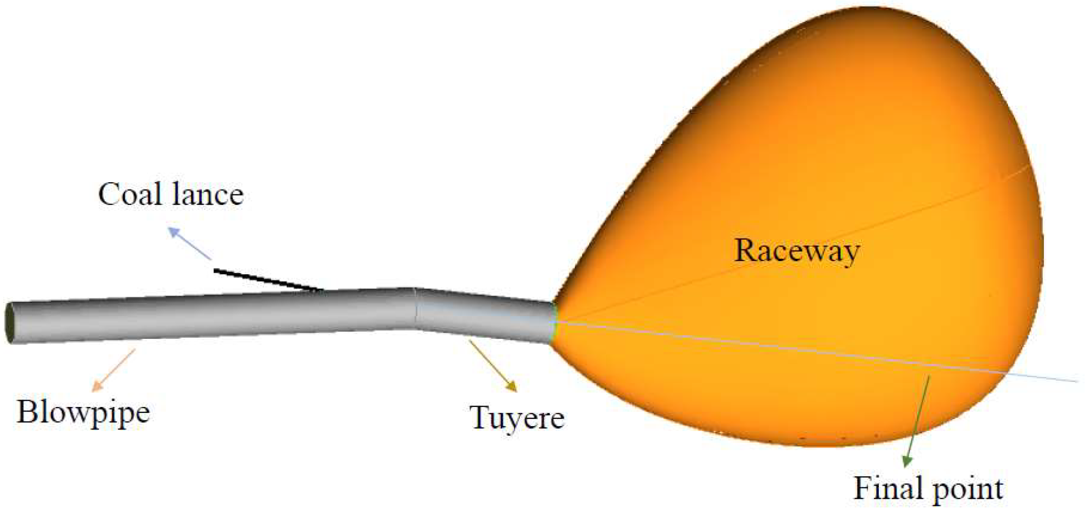
Figure 1. Geometric model of tuyere and swirling area.
Energies 18 05141 g001
Figure 2. Velocity field cloud images of different cases.
Energies 18 05141 g002
Figure 3. Velocity at the tuyere in different cases.
Energies 18 05141 g003
Figure 4. Particle char distribution trajectories for different cases.
Energies 18 05141 g004
Figure 5. Distribution of CO and CO2 mass fractions in different cases.
Energies 18 05141 g005
Figure 6. H2 and O2 mass distribution in different cases.
Energies 18 05141 g006
Figure 7. Changes in the contents of CO, CO2 and O2 in different cases in the tuyere whirling area.
Energies 18 05141 g007
Figure 8. Changes in the temperature field in the tuyere gyration zone in different cases.
Energies 18 05141 g008
Figure 9. Temperature field changes in different cases with distance from the coal gun outlet.
Energies 18 05141 g009
Figure 10. Changes in temperature at the tuyere and whirling zone.
Energies 18 05141 g010
Figure 11. Burnout rate of pulverized coal under different working conditions.
Energies 18 05141 g011
Figure 12. Changes in volatile matter on the center line of the tuyere.
Energies 18 05141 g012
Table 1. Main parameters and indicators of tuyere injection fuel.
ParameterValue
Wind pressure/KPa380
Air volume/m3/min5190
Hot air temperature/K1470
Oxygen concentration/%27
Coal ratio/kg/t160
Carrier gas flow/m3/h1820
Carrier gas composition/%N2
Carrier gas temperature/K295
Table 2. Basic performance parameters of injection fuel. (a represents the result obtained by subtraction).
Fuel TypeProximate AnalysisUltimate Analysis
FCd aAdVdCdafHdafOdaf aNdafSdaf
Bituminous coal61.033.7335.2469.934.6624.310.790.31
Anthracite80.4512.187.3782.153.0512.751.060.99
hydrochar65.127.1627.7274.813.5019.311.880.50
40% bituminous coal + 60% anthracite72.688.8018.5277.263.6917.370.950.72
40% hydrochar + 60% anthracite74.3210.1715.5179.213.2315.371.390.79
Table 3. Different conditions before and after injection of hydrochar.
Num.CombinationOxygen Concentration/%Average Particle Size/μm
140% bituminous coal + 60% anthracite coal27<74
240% hydrochar + 60% anthracite27<74
340% bituminous coal + 60% anthracite coal30<74
440% hydrochar + 60% anthracite30<74
Table 4. Governing formulas for gas phase and solid phase reactions.
Gas Phase Part
Mass ( ρ U ) = n p m ·
Momentum ( ρ U U ) ( μ + μ T ) U + ( U ) T = ( p + 2 3 ρ k ) + n p f D
Energy ρ U H λ C P + μ t σ H H = n p q
Gas species i ρ U Y i Γ i + μ t σ Y i Y i = W i
Turbulent kinetic energy ρ U k μ + μ t σ k k = p k ρ ε
Turbulent dissipation rate ρ U ε μ + μ t σ ε ε = ε k C 1 p k C 2 ρ ε
Solid Phase Part
Mass d m p d t = m ·
Momentum m p d U p d t = f D f D = 1 8 π d p 2 ρ C D U U P ( U U P )
Energy m p C p d T P d t = q q = π d p λ N u ( T g T P ) + d m p d t H r e a c + A p ε p ( π I σ B T p 4 )
Table 5. Reaction equations.
Num.ReactionsAE (J/kg·mol)
1CαHβOγNδ + aO2→bCO2 + cH2O + dN22.119 × 10112.027 × 108
2CO + 0.5O2 = CO22.2 × 10121.67 × 108
3C + 0.5O2→CO1,360,0001.3 × 108
4C + CO2→2CO67,8001.63 × 108
5C + H2O→CO + H285,5001.4 × 108
6C + O2→CO212259.977 × 107
Disclaimer/Publisher’s Note: The statements, opinions and data contained in all publications are solely those of the individual author(s) and contributor(s) and not of MDPI and/or the editor(s). MDPI and/or the editor(s) disclaim responsibility for any injury to people or property resulting from any ideas, methods, instructions or products referred to in the content.