Article

Robust Backstepping Super-Twisting MPPT Controller for Photovoltaic Systems Under Dynamic Shading Conditions

1
Department of Industrial and Information Engineering and Economics, University of L’Aquila, 67100 L’Aquila, AQ, Italy
2
Department of Electrical Engineering, University of Engineering and Technology Peshawar, Bannu Campus, Bannu 28100, Pakistan
*
Authors to whom correspondence should be addressed.
Energies 2025, 18(19), 5134; https://doi.org/10.3390/en18195134
Submission received: 21 August 2025 / Revised: 12 September 2025 / Accepted: 19 September 2025 / Published: 26 September 2025
(This article belongs to the Special Issue Experimental and Numerical Analysis of Photovoltaic Inverters)

Abstract

In this research article, a fast and efficient hybrid Maximum Power Point Tracking (MPPT) control technique is proposed for photovoltaic (PV) systems. The method combines two phases—offline and online—to estimate the appropriate duty cycle for operating the converter at the maximum power point (MPP). In the offline phase, temperature and irradiance inputs are used to compute the real-time reference peak power voltage through an Adaptive Neuro-Fuzzy Inference System (ANFIS). This estimated reference is then utilized in the online phase, where the Robust Backstepping Super-Twisting (RBST) controller treats it as a set-point to generate the control signal and continuously adjust the converter’s duty cycle, driving the PV system to operate near the MPP. The proposed RBST control scheme offers a fast transient response, reduced rise and settling times, low tracking error, enhanced voltage stability, and quick adaptation to changing environmental conditions. The technique is tested in MATLAB/Simulink under three different scenarios: continuous variation in meteorological parameters, sudden step changes, and partial shading. To demonstrate the superiority of the RBST method, its performance is compared with classical backstepping and integral backstepping controllers. The results show that the RBST-based MPPT controller achieves the minimum rise time of 0.018 s , the lowest squared error of 0.3015 V , the minimum steady-state error of 0.29 %, and the highest efficiency of 99.16 %.

1. Introduction

Due to global warming, declining air quality, growing economic concerns, and rising fuel prices worldwide, scientific research has increasingly focused on the development of potential alternative solutions—namely, Renewable Energy Sources (RESs) [1]. Many RESs are now well developed, reliable, and cost-competitive compared to conventional energy sources. Among these, photovoltaic (PV) solar energy stands out as one of the most important sources in modern power systems due to its desirable features, such as being clean, abundantly available, environmentally friendly, free of fuel cost, and requiring minimal maintenance [2,3].
As a result of these advantages, the demand for PV-based power generation has increased significantly over the past decade. However, its widespread adoption is still limited by two major challenges: the high installation cost of PV systems and their relatively low efficiency under varying meteorological conditions [4]. To improve system efficiency, extensive research has been conducted in three main areas: the development of sun-tracking systems, the implementation of efficient power converter topologies, and the design of MPPT control techniques.
The first two approaches are typically considered during the design and implementation of new PV systems. In contrast, MPPT control strategies can be integrated into both existing and new systems, making them highly adaptable. MPPT algorithms are essential for ensuring that the PV system consistently operates at or near the maximum power point (MPP) to maximize energy harvest. Accordingly, numerous MPPT techniques have been proposed in the literature to locate and track the MPP, even under dynamically changing environmental conditions.
According to reference [5,6], MPPT control techniques can be broadly classified into three categories: offline, online, and hybrid methods, as illustrated in Figure 1.

1.1. Model-Based MPPT Control Techniques

In model-based MPPT control techniques, the maximum power point is determined in an offline manner by exploiting data provided by the manufacturer or is obtained through initial experimental measurements [7]. These techniques typically utilize the technical specifications of the solar panel, such as open-circuit voltage and short-circuit current, calculated under specific meteorological conditions, to estimate the main MPP parameters—namely, V M P P , I M P P , and the duty cycle D. These estimated parameters are then fed into the photovoltaic system to drive the solar cell toward its maximum power point.
One of the simplest offline MPPT control techniques is based on open-circuit voltage (OCV), which uses an approximately linear relationship between the MPP voltage ( V M P P ) and the open-circuit voltage ( V o c ) under varying environmental conditions. This relationship is expressed by the following equation [8]:
V M P P = K m v V o c
Equation (1) forms the basis for the development of voltage-based MPPT control techniques. The parameter K m v is a constant known as the voltage factor, and its value typically ranges between 0.7 and 0.95, depending entirely on the characteristics of the PV panel.
Another offline MPPT control technique is the short-circuit current (SCC) method. Similar to the OCV method, the SCC technique also exploits an approximately linear relationship—this time between the MPP current ( I M P P ) and the short-circuit current ( I s c ), as expressed by the following equation:
I M P P = K m i I s c
Equation (2) is fundamental to the design of current-based MPPT control techniques. The parameter K m i is a proportionality constant known as the current factor, and its value typically ranges between 0.7 and 0.9, depending on the solar cell material and PV panel characteristics.
Other offline MPPT control techniques include look-up table methods [9], curve-fitting techniques [10], and artificial intelligence-based approaches [11]. However, a major limitation of offline MPPT techniques is that the MPP calculation is based on estimations, which can lead to steady-state deviations. Moreover, these techniques generally fail to accurately track the MPP under rapidly changing meteorological conditions and are ineffective in handling partial shading conditions (PSCs).

1.2. Model-Free MPPT Control Techniques

In model-free MPPT techniques, the maximum power point is calculated using an online approach based on real-time measurements of photovoltaic voltage and/or current. These control methods do not require solar irradiance and temperature measurements, nor do they rely on a mathematical model of the PV array.
The Perturb and Observe (P&O) algorithm is one of the simplest and most widely studied online methods, as reported by several researchers [11,12]. The P&O technique perturbs (i.e., incrementally increases or decreases) the PV terminal voltage or current and observes the resulting change in output power. This perturbation is implemented by slightly adjusting the duty cycle of the power electronic converter. If the change in power is positive (i.e., d P / d V p v > 0 ), the algorithm continues perturbing in the same direction. Conversely, if the change in power is negative (i.e., d P / d V p v < 0 ), the perturbation direction is reversed. This iterative process continues until the system reaches the maximum power point (MPP) [13].
The Incremental Conductance (IncCond) method is another commonly used online MPPT approach. It is based on the principle that the condition d I p v d V p v = I p v V p v holds true at the MPP. If d I p v d V p v > I p v V p v , the PV module operates on the left side of the MPP on the power–voltage curve. Conversely, if d I p v d V p v < I p v V p v , the system operates on the right side of the MPP [14]. The duty cycle of the electronic converter is then adjusted accordingly to track the MPP.
Other online MPPT techniques include differentiation-based MPPT, transient-based MPPT, and power feedback methods. Although online techniques are generally simple to implement and are effective under normal meteorological conditions, they exhibit oscillations around the MPP during steady-state operation. These oscillations result in power losses and reduced system efficiency. Additionally, most online techniques are not well suited for handling partial shading conditions.

1.3. Hybrid MPPT Control Techniques

Hybrid MPPT control techniques combine model-based (offline) and model-free (online) approaches to achieve more efficient tracking of the maximum power point (MPP). These techniques are designed to overcome the limitations of individual methods by leveraging their complementary strengths [5]. Typically, the control signal generated by a hybrid MPPT algorithm consists of two components. The first component uses simplified offline techniques to estimate a real-time reference voltage ( V M P P ) corresponding to peak power, which depends on the PV cell’s meteorological conditions and represents a steady-state target. The second component, derived from an online control technique, uses this estimated reference as a set-point to generate the control input u, driving the PV system to operate at the MPP.
In [15], the authors proposed a hybrid MPPT method comprising two loops: the first loop uses the open-circuit voltage technique to estimate V M P P , and the second applies the Perturb and Observe (P&O) algorithm to track this reference and operate the PV system accordingly. Similarly, in [16], a hybrid analog MPPT technique is introduced, where V M P P is estimated using the OCV method, and P&O is employed in a fine-tuning loop for enhanced tracking performance.
However, due to the nonlinear characteristics of power converters and PV arrays, MPPT control becomes a highly nonlinear problem. Therefore, the application of nonlinear control strategies can provide more robust and efficient solutions.
One such approach is the backstepping control method. In [17], a nonlinear hybrid two-loop backstepping controller was developed for a standalone PV system. The first loop employs a regression plane to estimate the real-time MPP voltage, while the second uses a backstepping controller to regulate the system at this estimated voltage. Although effective, this method exhibits significant steady-state error and slow dynamic response. These issues were partially addressed in [18], where the steady-state error was reduced; however, the system still suffered from overshoot and undershoot during transient conditions.
Another nonlinear technique used in MPPT is Sliding Mode Control (SMC). In [19], a hybrid two-loop terminal SMC approach was proposed, which requires either a voltage or current reference. In contrast, [20] presents an SMC-based MPPT technique that does not rely on a reference value, as the sliding surface itself guarantees convergence to the MPP when it reaches zero. A major limitation of classical SMC is the chattering phenomenon, which was addressed in [21]. To further suppress chattering, a state-dependent approach was developed in [22]. However, experimental results still revealed residual oscillations caused by chattering.
In [23], the authors reported a fast super-twisting algorithm (STA)-based improved SMC to achieve finite-time convergence of the speed and position errors of a permanent magnet synchronous motor (PMSM). The same authors later proposed another novel composite adaptive reaching law-based SMC [24] for precise and robust speed regulation of PMSMs under internal and external disturbances. This strategy adaptively tunes the sliding mode gain according to system state variations and incorporates a damping term for disturbance compensation, which effectively mitigates chattering and enhances robustness against disturbances.

1.4. Motivation and Contribution of This Work

The key motivation of this research article is to address the shortcomings of conventional MPPT techniques, such as steady-state error, slow convergence, and chattering. To overcome these issues, we propose a nonlinear two-loop hybrid Robust Backstepping Super-Twisting (RBST) MPPT control technique for standalone PV systems. In the first loop, an Adaptive Neuro-Fuzzy Inference System (ANFIS) is employed to estimate the offline reference maximum power point voltage ( V M P P ), while in the second loop, this estimated V M P P is used as the reference for the RBST control law, which continuously regulates the duty cycle of a non-inverting DC–DC buck–boost converter.
The scientific novelty and major contributions of this work are as follows:
  • Hybrid RBST–ANFIS MPPT design: A new hybrid scheme is formulated where ANFIS provides offline V M P P estimation and the RBST law ensures online tracking. This integration of intelligent reference generation with Lyapunov-based robust control represents a novel approach in PV MPPT applications.
  • Explicit Lyapunov-based RBST formulation: The RBST controller is systematically derived using Lyapunov stability theory, introducing six tuning parameters ( κ 1 κ 6 ), whose roles are explicitly analyzed in terms of convergence speed, robustness, and chattering reduction.
  • Super-twisting within a two-loop backstepping framework: By embedding the super-twisting algorithm inside a two-loop backstepping design, the proposed controller achieves finite-time convergence, eliminates steady-state error, and mitigates chattering compared to classical backstepping and sliding-mode MPPT schemes.
  • Duty-cycle boundedness: This method guarantees that the converter duty cycle remains bounded ( 0 < u < 1 ) throughout operation, which is an explicit design constraint often overlooked in nonlinear MPPT schemes.
  • Superior MPPT performance: Simulation results confirm >99% MPPT efficiency and fast convergence (∼0.018 s rise time) across highly dynamic irradiance and shading conditions, validating both robustness and practicality.
  • Integration with a broader research framework: This work also contributes to a wider ongoing PhD project on PV plant development and monitoring, in which the proposed MPPT scheme represents the efficiency-optimization stage that can be linked with geospatial decision support, GIS-based site selection [25], and land surface temperature (LST) downscaling techniques [26], thereby enhancing PV system monitoring and improving overall energy efficiency.

1.5. Organization of This Article

Section 2 presents the mathematical modeling of the solar array, while Section 3 focuses on the mathematical representation of the DC–DC power converter. Section 4 outlines the ANFIS-based reference peak power voltage generation for the MPPT controller. Section 5 presents the proposed Robust Backstepping-based Super-Twisting MPPT controller. Section 6 provides a detailed analysis of the simulation results and their corresponding discussion. Finally, Section 7 concludes this article with a summary of the key findings and implications.

2. Solar Array Mathematical Modeling

A PV cell is the basic building block of a typical PV system. It is essentially a semiconductor diode with a PN-junction that is capable of converting sunlight directly into electricity through the photoelectric effect when exposed to sunlight. To obtain higher output voltages at the terminals, multiple PV cells are connected in series, forming a PV module or PV panel. Similarly, to obtain higher output currents, many PV cells—or equivalently, multiple PV modules—are connected in parallel. A set of series-connected PV modules constitutes a PV string, while a PV array may consist of either a single PV module or a combination of modules connected in a series–parallel configuration, or equivalently, a set of parallel-connected PV strings [27].
The mathematical model of a PV cell is of particular interest in studying the dynamic behavior of power electronic converters and MPPT algorithms. Several equivalent circuit models of the PV cell are available in the scientific literature, including (i) single-diode-based, (ii) two-diode-based, and (iii) three-diode-based equivalent circuit models. The single-diode-based equivalent circuit model has been frequently used by many authors, as it is not only simple but also offers reasonable accuracy [28].
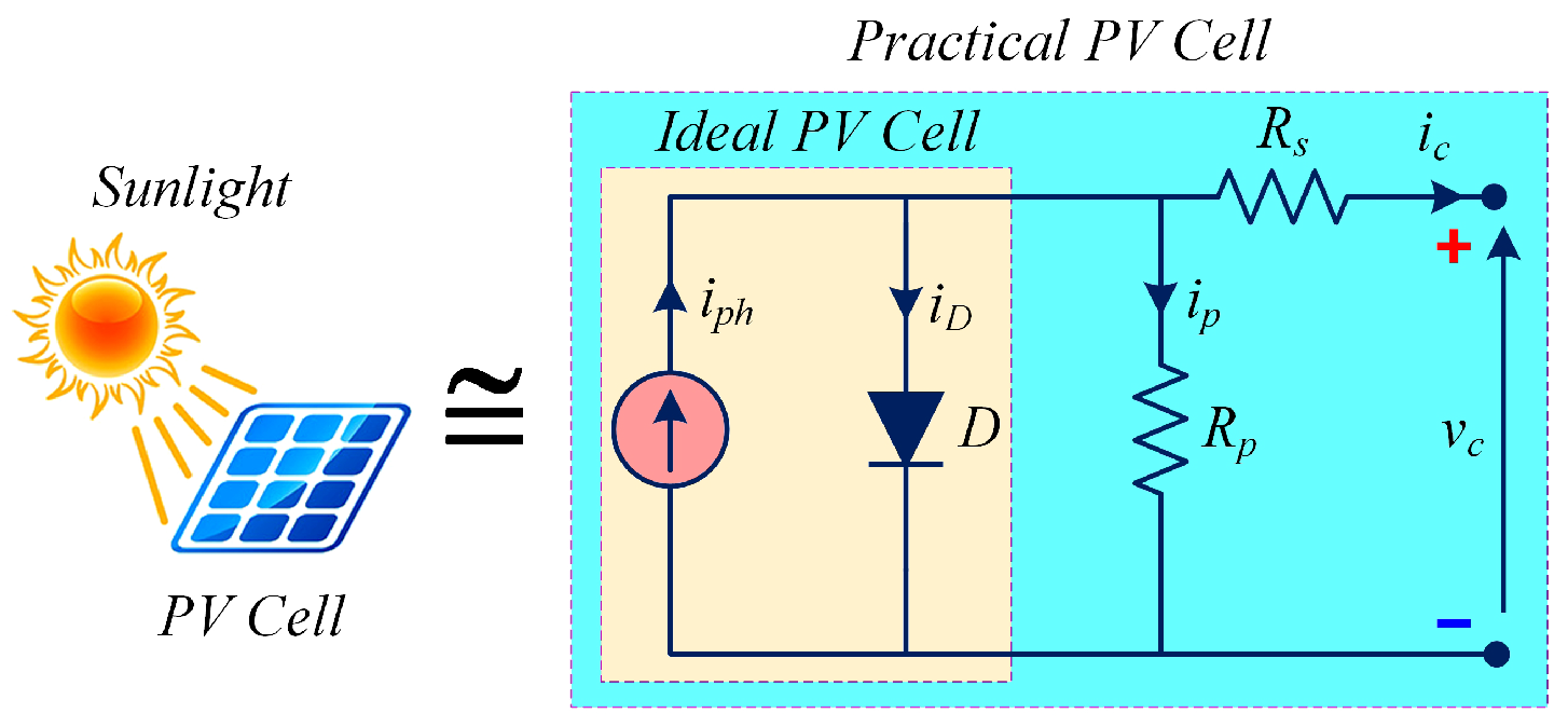
A single-diode-based equivalent circuit model of a practical PV cell consists of a light-dependent current source, i p h , an anti-parallel diode, D, a small series resistance, R s , and a very large parallel resistance, R p , as illustrated in Figure 2.
The PV cell output current, i c , can be derived from the circuit shown in Figure 2 by applying Kirchhoff’s current law, as follows:
i c = i p h i D i p = i p h I 0 exp v c + R s i c α V t 1 v c + R s i s R p .
Equation (3) gives the relation between the terminal quantities of the PV cell (i.e., v c and i c ), where v c is the PV cell output voltage, i p h is the light-generated current (directly proportional to the incident solar irradiance), I D is the Shockley diode current, I 0 is the leakage current or reverse saturation current of the diode, α is the diode ideality constant (usually 1 α 1.5 ), and V t = k T / q is the cell thermal voltage. Here, k is Boltzmann’s constant ( 1.3806503 × 10 23 J / K ), T is the PN-junction temperature of the cell (in Kelvin), and q is the electron charge ( 1.60217646 × 10 19 C ).
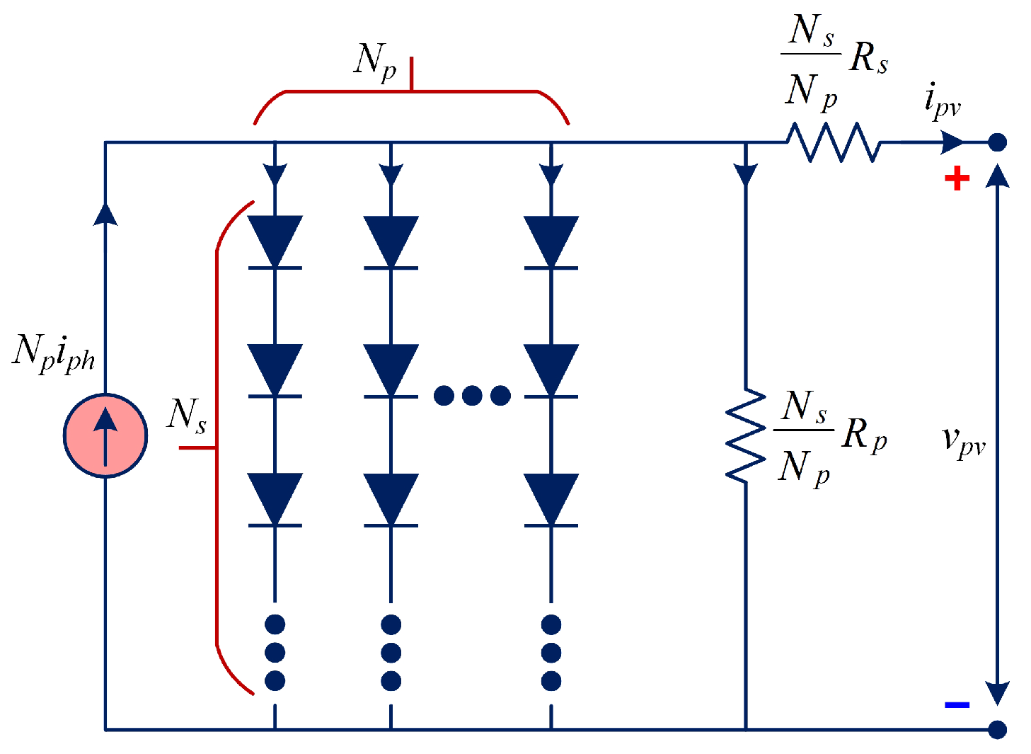
The mathematical relationship between the terminal quantities of the PV array (i.e., array output voltage v p v and current i p v ), with N p parallel-connected modules and N s series-connected cells, as shown in Figure 3, can be expressed as follows [29,30]:
i p v = N p i p h N p I 0 exp q α k T v p v N s + i p v R s N p 1 N p R p v p v N s + i p v R p N p .
Various characteristics of PV modules are specified in their datasheets by manufacturers under certain test conditions, known as Standard Test Conditions (STCs), which imply an irradiance (G) of 1000 W/m2, a temperature (T) of 25 °C, and an air mass (AM) of 1.50 [27]. In this work, a preset single Kyocera Solar KC200GT module has been used in MATLAB/Simulink https://www.mathworks.com/products/matlab/student.html accessed on 20 August 2025, whose electrical characteristics under STC are given in Table 1.
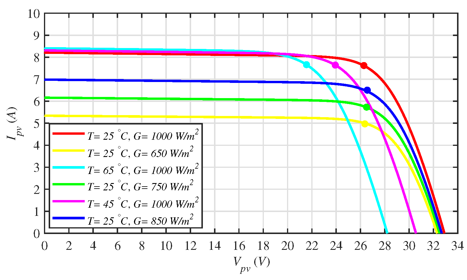
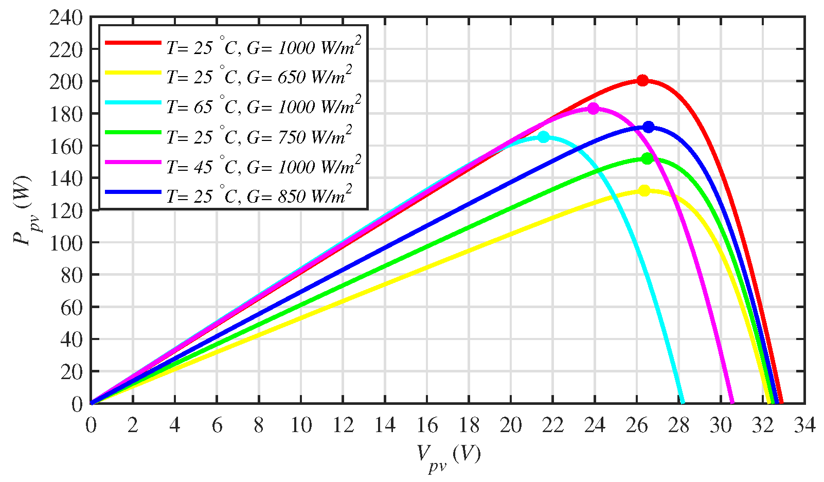
Figure 4 presents the current–voltage (I–V) characteristics of the Kyocera Solar KC200GT PV module at a fixed temperature of 25 °C under varying irradiance levels ranging from 650 W / m 2 to 1000 W / m 2. Similarly, Figure 5 illustrates the corresponding power–voltage (P–V) characteristics of the same PV module under identical conditions.
i p v = N p i p h N p I 0 exp q α k T v p v N s + i p v R s N p 1 N p R p v p v N s + i p v R p N p

3. Mathematical Modeling of DC–DC Power Converter

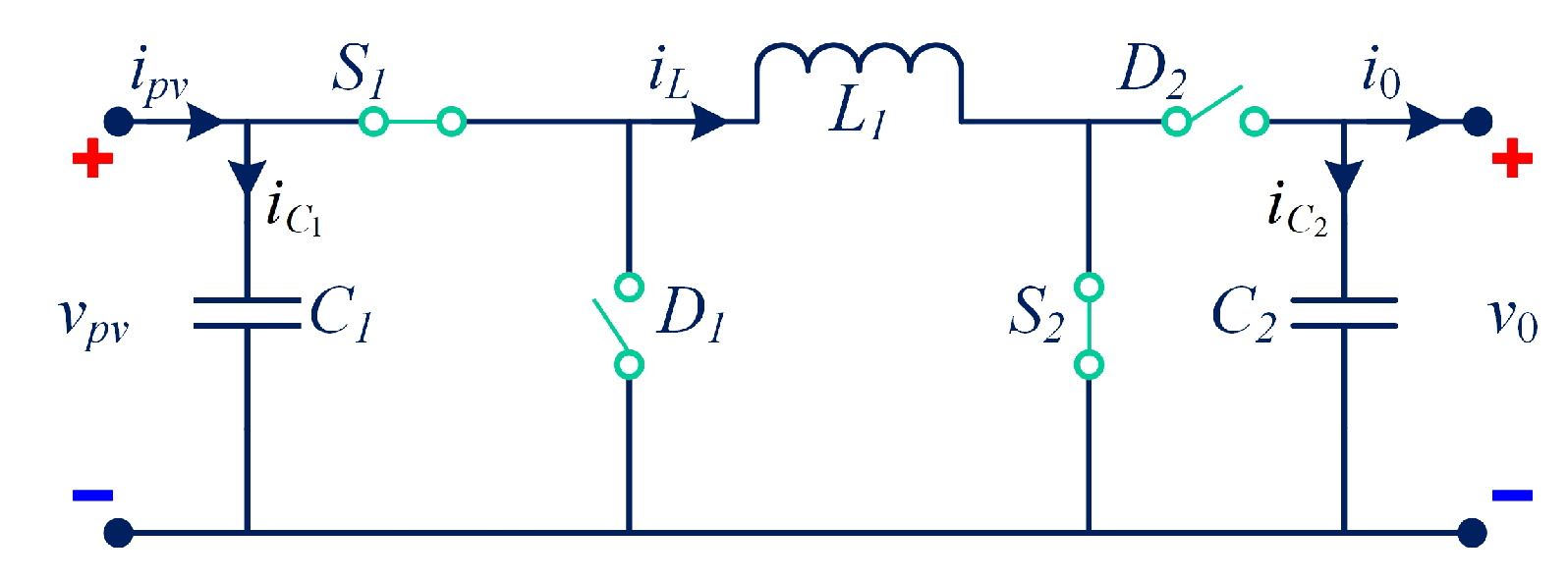
The PV array is interfaced with a load, R L , through a non-inverting buck–boost power converter (NIBBPC). In this work, the mathematical model of the NIBBPC is derived using state-space averaging, which provides a solid foundation for dynamic modeling and control of the power converter [31]. Figure 6 illustrates the equivalent electric circuit of the NIBBPC [32,33], showing the input (from the PV array) and the output (to the load, R L ). In this circuit, v p v denotes the total PV array voltage, v 0 represents the NIBBPC output voltage, S 1 and S 2 are the two controllable power electronic switches, D 1 and D 2 are the two diodes, and C 1 and C 2 are the input and output capacitors, respectively.
The NIBBPC can operate in three different modes:
  • Buck Mode:  S 1 is switched ON and OFF during one switching period, T s , while S 2 remains continuously OFF.
  • Boost Mode:  S 2 is switched ON and OFF during one switching period, while S 1 remains continuously ON.
  • Buck–Boost Mode: Both S 1 and S 2 are switched ON and OFF during the same switching period [33,34].
These three operating modes of the NIBBPC are summarized in Table 2.
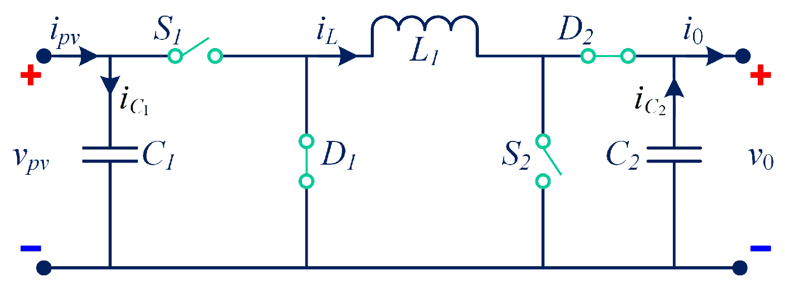
In this work, the NIBBPC operates in buck–boost mode. Figure 7 and Figure 8 illustrate the equivalent electrical circuits of the NIBBPC during two distinct switching intervals within a single switching period.
Referring to Figure 7, and assuming the converter operates in continuous conduction mode (CCM), the state-space equations for operation during switching interval 1 (with S 1 and S 2 ON, while D 1 and D 2 are OFF) of the NIBBPC can be expressed as follows:
d v p v d t = ( 0 ) v p v + 1 C 1 i L + ( 0 ) v 0 + i p v C 1 d i L d t = 1 L v p v + ( 0 ) i L + ( 0 ) v 0 d v 0 d t = ( 0 ) v p v + ( 0 ) i L + 1 R L C 2 v 0 .
Similarly, referring to Figure 8, the state-space equations for operation in switching interval 2 (with S 1 , S 2 : OFF, while D 1 , D 2 : ON) of the NIBBPC can be expressed as follows:
d v p v d t = ( 0 ) v p v + ( 0 ) i L + ( 0 ) v 0 + i p v C 1 d i L d t = ( 0 ) v p v + ( 0 ) i L + 1 L v 0 d v 0 d t = ( 0 ) v p v + 1 C 2 i L + 1 R L C 2 v 0 .
Now, the overall state-space averaged model of the NIBBPC, averaged over one switching period, T s , based on the inductor volt-second balance and capacitor charge balance principles, can be described as follows:
d v ¯ p v d t = ( 0 ) v ¯ p v + d C 1 i ¯ L + ( 0 ) v ¯ 0 + i p v C 1 d i ¯ L d t = d L v ¯ p v + ( 0 ) i ¯ L + d 1 L v ¯ 0 d v ¯ 0 d t = ( 0 ) v ¯ p v + 1 d C 2 i ¯ L + 1 R L C 2 v ¯ 0 ,
where v ¯ p v , i ¯ L , and v ¯ 0 are the average values of v p v , i L , and v 0 , respectively, and d is the duty ratio of the NIBBPC switches. Considering v p v , i L , and v 0 as the system state variables, the dynamics of the NIBBPC can be expressed in state-space form as follows [31]:
x ¯ ˙ = A ¯ x ¯ + B ¯ u ¯ y ¯ = C ¯ x ¯ ,
where x is the state vector, x ¯ is the average value of x , x ¯ ˙ = d x / d t , u is the control or input vector, y is the output vector, and A , B , and C are, respectively, the state (or dynamics), the input, and the output matrices.
x ¯ = v ¯ p v i ¯ L v ¯ 0 T A ¯ = 0 d C 1 0 d L 0 d 1 L 0 1 d C 2 1 R L C 2 T B ¯ = 1 C 1 0 0 u ¯ = i p v y ¯ = v ¯ p v C ¯ = 1 0 0
The various parameters of the NIBBPC are listed in Table 3.

4. ANFIS-Based Reference Peak Power Voltage Generation for MPPT Controller

This section describes the strategy for generating the PV module’s reference peak power voltage, V M P P or v p v r e f , which must be accurately tracked by the proposed MPPT controller to extract the maximum possible power from the PV module. This reference voltage is generated using an Adaptive Neuro-Fuzzy Inference System (ANFIS).
ANFIS is a multiple-input single-output (MISO) system [35]. Using the built-in MATLAB/Simulink model of the PV module, an input–output training dataset is acquired for ANFIS by varying the temperature (input variable) from 15 °C to 65 °C in uniform steps of 5 °C, and the irradiance (input variable) from 100 W / m 2 to 1000 W / m 2, in uniform steps of 50 W / m 2, while recording the corresponding V M P P (output variable). In this way, a dataset comprising around 200 different input–output combinations is obtained. This dataset is then used to train ANFIS for V M P P estimation. Once trained, the ANFIS model is employed during simulations for real-time V M P P estimation, corresponding to any combination of temperature and irradiance applied to the PV module.
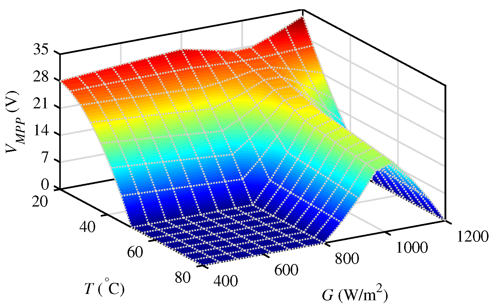
The ANFIS-generated three-dimensional (3-D) surface is depicted in Figure 9. It is a 3-D plot showing the relationship between the two input variables (i.e., temperature and irradiance) and the output variable (i.e., V M P P ). This surface indicates that the V M P P of the PV module increases with increasing irradiance levels but remains at a higher value at moderate temperatures. This observation clearly verifies the P p v vs. V p v and I p v vs. V p v curves of the PV module obtained from the built-in MATLAB/Simulink model and are depicted in Figure 4 and Figure 5.
The various parameters used for ANFIS training are listed in Table 4.
It is worth noting that the ANFIS model used for V M P P estimation in this work is trained on datasets generated from MATLAB/Simulink under controlled irradiance and temperature conditions. This ensures accurate mapping between environmental variables and the corresponding V M P P . In practice, however, PV systems are subject to disturbances, such as sensor noise, slight parameter drift, and variability beyond the trained dataset. The feasibility of the proposed approach is supported by the fact that the combined ANFIS–RBST framework has been validated under representative operating conditions, including gradual daily variations, sudden irradiance changes, and partial shading scenarios, which are commonly encountered in real PV installations. These results demonstrate that the offline-trained ANFIS model, when coupled with the robust RBST controller, maintains reliable performance under realistic and dynamic conditions, indicating its practical applicability for PV systems.

5. The Proposed Robust Backstepping-Based Super-Twisting MPPT Controller Design

This section focuses on the proposed RBST controller design. It consists of a backstepping-based continuous (or equivalent) control law, u e q , and a super-twisting-based discontinuous (or switching) control law, u d i s c .

5.1. Robust Backstepping-Based Continuous/Equivalent Control Design

Backstepping control is considered a breakthrough in nonlinear system control. It is a recursive control procedure based on the Lyapunov function and is applicable to a special class of nonlinear systems (called strict-feedback systems or triangular systems). It derives its name from the recursive design process, which starts with a scalar equation and then steps backward toward the control input, with the two separated by a chain of integrators [36]. This approach can guarantee global stability of the system and improve tracking and transient performance. It has the capability to handle unmeasured or missing system states, unknown system parameters, stochastic disturbances, zero dynamics, and systems that are neither feedback linearizable nor completely controllable. For finite-dimensional nonlinear systems, the backstepping control strategy can be regarded as an extension of feedback linearization control [37].
The backstepping-based equivalent controller, u e q , will be designed in two steps. However, before initiating the controller design, certain modifications are made as follows:
x 1 = v ¯ p v x 1 r e f = v p v r e f x 2 = i ¯ L x 3 = v ¯ 0 u = d } .
Now, by substituting Equation (10) into Equation (8), the latter can be rewritten as follows:
x ˙ 1 = u x 2 C 1 + i p v C 1 x ˙ 2 = u x 1 L + u 1 x 3 L x ˙ 3 = 1 u x 2 C 2 x 3 R L C 2 .
Step 1
The PV array output voltage error, ξ 1 , is defined as
ξ 1 = x 1 x 1 r e f .
Note that the objective of the MPPT algorithm design is to drive the error ξ 1 to zero.
Using Equations (11) and (12), the time derivative of ξ 1 can be expressed as follows:
ξ ˙ 1 = x ˙ 1 x ˙ 1 r e f = u x 2 C 1 + i p v C 1 x ˙ 1 r e f .
Now, let V f 1 be chosen as a scalar Lyapunov function candidate to verify the convergence of the error ξ 1 to the equilibrium point O, as follows:
V f 1 = 1 2 ξ 1 2 .
To ensure the asymptotic stability of the closed-loop system, the Lyapunov function candidate V f 1 must satisfy the following conditions: (i) it must be positive definite, (ii) it must be radially unbounded, and (iii) it must have a negative definite time derivative [38,39].
Now, the time derivative of Equation (14) can be expressed as follows:
V ˙ f 1 = ξ 1 ξ ˙ 1 .
Substituting ξ ˙ 1 from Equation (13) into Equation (15) yields
V ˙ f 1 = ξ 1 i p v C 1 u x 2 C 1 x ˙ 1 r e f .
For V ˙ f 1 to be negative definite, the following condition must be satisfied:
i p v C 1 u x 2 C 1 x ˙ 1 r e f = κ 1 ξ 1 κ 2 sign ( ξ 1 ) ,
where κ 1 , κ 2 > 0 are positive design constants.
The condition stated in Equation (17) simplifies Equation (16) to the following form:
V ˙ f 1 = κ 1 ξ 1 2 κ 2 ξ 1 sign ( ξ 1 ) .
Now, let the second state of the system, that is, the average inductor current x 2 = i ¯ L , serve as a virtual control input [36,37]. Then, the stabilization function—denoted by α —which acts as the reference (or desired) value for the actual inductor current x 2 , can be determined by comparing Equations (16) and (18), leading to the condition x 2 = α , as follows:
α = i p v C 1 x ˙ 1 r e f + κ 1 ξ 1 + κ 2 sign ( ξ 1 ) C 1 u ,
where α acts as a new reference for the next step.
Step 2
Now, the inductor current, x 2 , can be tracked to its reference, α , by defining another error, ξ 2 , as follows:
ξ 2 = x 2 α x 2 = ξ 2 + α .
Substituting x 2 from Equation (20) into Equation (13), and then simplifying by substituting α from Equation (19), yields
ξ ˙ 1 = u ξ 2 + α C 1 + i p v C 1 x ˙ 1 r e f = κ 1 ξ 1 κ 2 sign ( ξ 1 ) u ξ 2 C 1 .
Substituting Equation (21) into Equation (15) yields
V ˙ f 1 = κ 1 ξ 1 2 κ 2 ξ 1 sign ( ξ 1 ) u ξ 1 ξ 2 C 1 .
Using the Quotient Rule of derivatives, the time derivative of Equation (19) is calculated and simplified by substituting α from Equation (19) and ξ ˙ 1 from Equation (21), which yields
α ˙ = 1 u i ˙ p v C 1 κ 1 2 ξ 1 C 1 x ¨ 1 r e f C 1 κ 1 κ 2 sign ( ξ 1 ) κ 1 ξ 2 u ˙ α u .
Taking the time derivative of ξ 2 in Equation (20) gives ξ ˙ 2 = x ˙ 2 α ˙ . Substituting x ˙ 2 and α ˙ from Equations (11) and (23), respectively, yields
ξ ˙ 2 = u x 1 L + ( u 1 ) x 3 L 1 u i ˙ p v C 1 κ 1 2 ξ 1 C 1 x ¨ 1 r C 1 κ 1 κ 2 sign ( ξ 1 ) + κ 1 ξ 2 + u ˙ α u .
Now, consider another augmented Lyapunov function candidate, V f 2 , which ensures the convergence of both errors, ξ 1 and ξ 2 , to the equilibrium point O, as well as the asymptotic stability of the closed-loop system, under the same assumptions made for V f 1 [38,39].
The newly chosen Lyapunov function candidate, V f 2 , and its time derivative, V ˙ f 2 , are given in Equations (25) and (26), respectively, as follows:
V f 2 = V f 1 + 1 2 ξ 2 2 ,
and
V ˙ f 2 = V ˙ f 1 + ξ 2 ξ ˙ 2 .
Substituting V ˙ f 1 from Equation (22) into Equation (26) yields
V ˙ f 2 = κ 1 ξ 1 2 κ 2 ξ 1 sign ( ξ 1 ) + ξ 2 ξ ˙ 2 u ξ 1 C 1 .
For V ˙ f 2 to be negative definite, the following condition must be satisfied:
ξ ˙ 2 u ξ 1 C 1 = κ 3 ξ 2 κ 4 sign ( ξ 2 ) ,
where both κ 3 and κ 4 are positive design constants.
The condition stated in Equation (28) simplifies Equation (27) to the following:
V ˙ f 2 = κ 1 ξ 1 2 κ 2 ξ 1 sign ( ξ 1 ) κ 3 ξ 2 2 κ 4 ξ 2 sign ( ξ 2 ) .
Substituting V ˙ f 1 from Equation (22) and ξ ˙ 2 from Equation (24) into Equation (26) yields
V ˙ f 2 = κ 1 ξ 1 2 κ 2 ξ 1 sign ( ξ 1 ) u ξ 1 ξ 2 C 1 + ξ 2 [ u x 1 L + ( u 1 ) x 3 L 1 u i ˙ p v C 1 κ 1 2 ξ 1 C 1 x ¨ 1 r e f C 1 κ 1 κ 2 sign ( ξ 1 ) + κ 1 ξ 2 + u ˙ α u ] .
Now, comparing Equations (29) and (30) and solving for u ˙ yields
u ˙ = u α [ κ 3 ξ 2 + κ 1 ξ 2 + κ 4 sign ( ξ 2 ) + u x 1 L + ( u 1 ) x 3 L 1 u ( i ˙ p v C 1 κ 1 2 ξ 1 C 1 x ¨ 1 r e f C 1 κ 1 κ 2 sign ( ξ 1 ) ) u ξ 1 C 1 ] .
Simplifying Equation (31) yields the robust backstepping-based equivalent control law, u e q , as follows:
u ˙ e q = 1 α [ ξ 2 κ 1 + κ 3 u ξ 1 C 1 κ 1 2 u 2 C 1 u 2 x 1 L u ( u 1 ) x 3 L + i ˙ p v C 1 x ¨ 1 r e f C 1 κ 1 κ 2 sign ( ξ 1 ) κ 4 u sign ( ξ 2 ) ] ,
where α 0 .

5.2. Super-Twisting-Based Discontinuous Control Design

The super-twisting-based discontinuous control law, u d i s c , is designed as follows [40]:
u ˙ d i s c = κ 5 | ξ 1 | sign ξ 1 κ 6 sign ξ 1 d t ,
where κ 5 and κ 6 are positive design constants.

5.3. Proposed RBST-Based MPPT Control Law

Finally, the proposed RBST-based MPPT control law, u, is given as follows:
u ˙ = u ˙ d i s c + u ˙ e q = κ 5 | ξ 1 | sign ξ 1 κ 6 sign ξ 1 d t + 1 α [ ξ 2 κ 1 + κ 3 u ξ 1 C 1 κ 1 2 u 2 C 1 u 2 x 1 L u ( u 1 ) x 3 L + i ˙ p v C 1 x ¨ 1 r e f C 1 κ 1 κ 2 sign ( ξ 1 ) κ 4 u sign ( ξ 2 ) ] .
In Equation (34), 0 < u < 1 . As lim t v p v = V M P P , it follows that lim t P p v = P M P P as well. Note that the proposed RBST-based MPPT control law, u, continuously adjusts the duty cycle, d, of the NIBBPC switches, S 1 and S 2 , as shown in Figure 7 and Figure 8, and adapts the PV system’s operating point ( V M P P ) to varying atmospheric conditions, thereby maximizing power output.
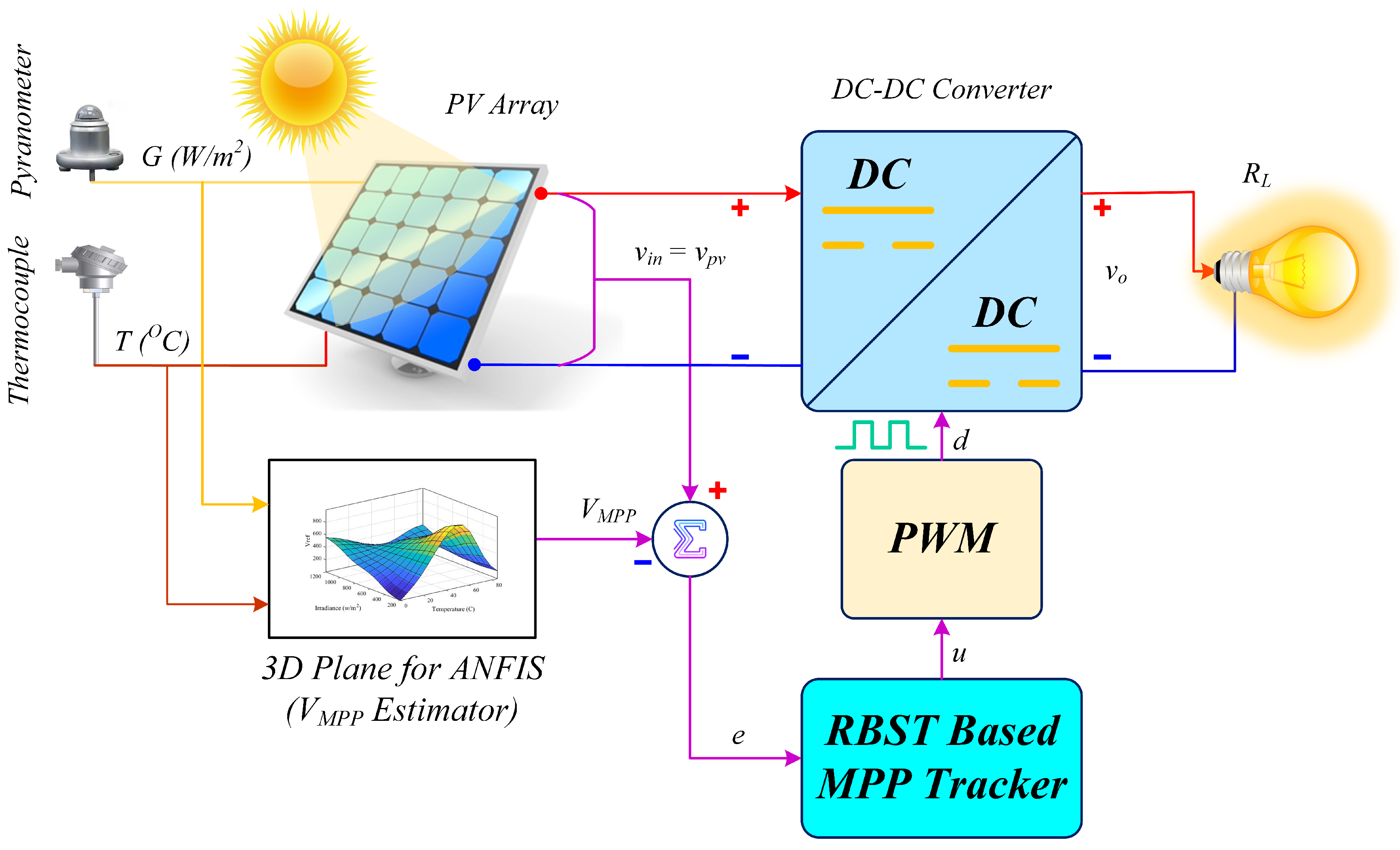
Table 5 lists the design parameters of the proposed RBST-based MPPT control law, whereas Figure 10 illustrates the overall closed-loop operation of the system.
The proposed RBST–ANFIS framework is computationally efficient despite combining advanced nonlinear control with an intelligent reference generator. The ANFIS used in this work is lightweight, consisting of only two inputs, one output, and nine fuzzy rules, which results in a very small number of arithmetic operations during real-time execution. Similarly, the RBST controller mainly requires basic operations, such as additions, multiplications, sign evaluations, and a square-root term. No matrix inversions or iterative optimization steps are involved. When compared to conventional algorithms, like Perturb & Observe (P&O) or Incremental Conductance (IncCond), the proposed method requires slightly more computations per control cycle; however, this overhead is negligible for modern low-cost embedded platforms. For instance, ARM Cortex-M4/M7 or TI C2000 series microcontrollers, commonly used in PV applications, are capable of executing tens of thousands of such operations within microseconds. Therefore, the additional complexity does not hinder real-time feasibility. Given that the method consistently achieves above 99% tracking efficiency and superior accuracy under dynamic conditions, the trade-off between a modest increase in computational demand and substantial performance improvement is considered highly favorable for practical PV implementations.

6. Results and Discussion

To validate the superiority of the proposed RBST-based MPPT controller, its performance is compared with two well-established nonlinear MPPT control techniques: the backstepping controller and the integral backstepping controller. The simulations are conducted in the MATLAB/Simulink environment, which includes detailed modeling of the PV array, the non-inverting buck–boost power converter (NIBBPC), and the respective MPPT controllers. The key system parameters used for the simulations are summarized in Table 5.
To comprehensively assess the dynamic and steady-state performance of the controllers, all three MPPT strategies are tested under the following three operating conditions:
  • Continuously varying irradiance and temperature;
  • Sudden step changes in irradiance and temperature;
  • Partial shading conditions.

6.1. Continuously Varying Irradiance and Temperature

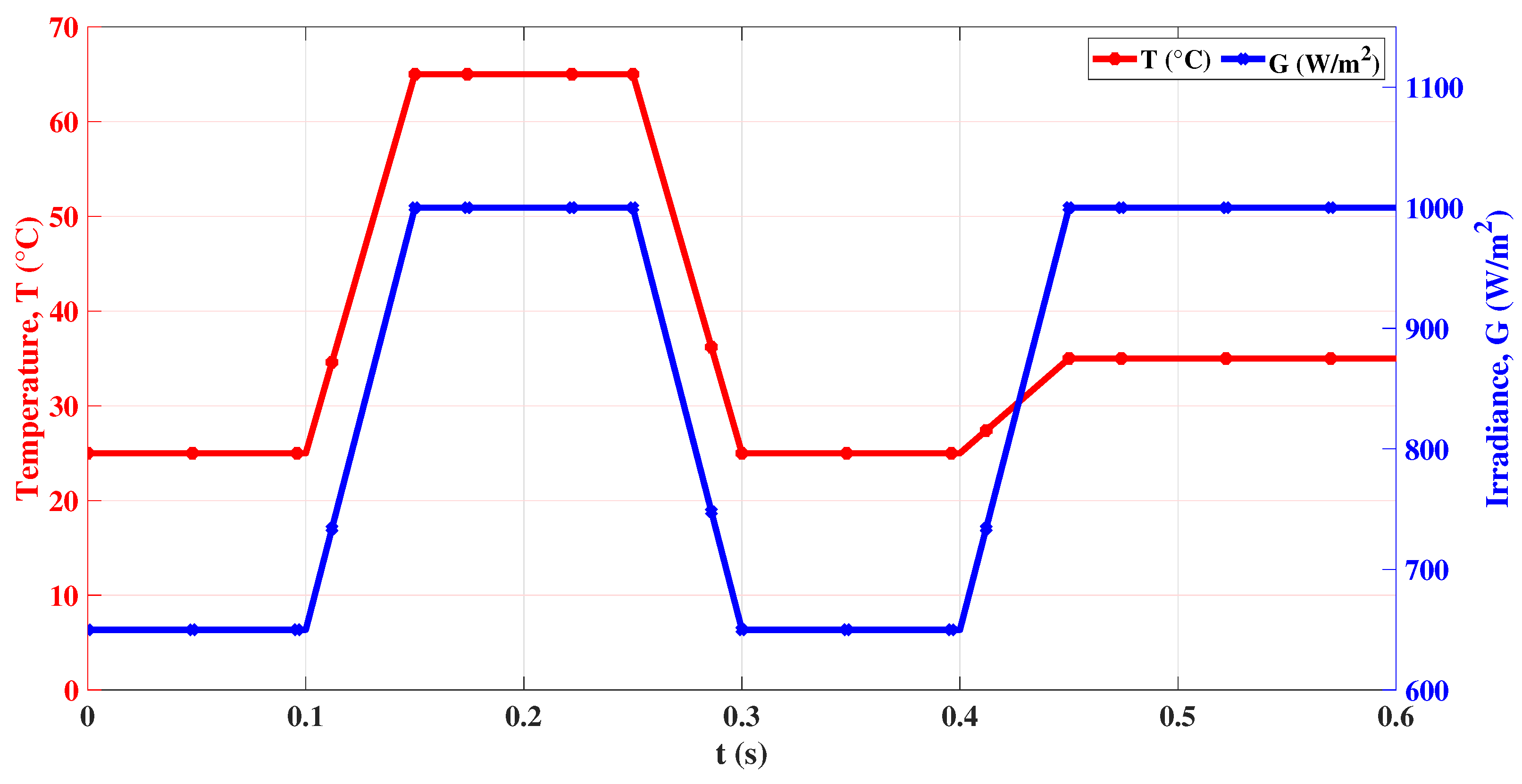
To evaluate the dynamic tracking capability of the proposed MPPT technique under continuously varying environmental conditions, a ramp-type irradiance and temperature profile is applied. This emulates a typical daily solar pattern, where irradiance and temperature gradually increase and decrease. The test scenario spans a total simulation time of 0.6   s , as shown in Figure 11. This setup enables a rigorous assessment of the MPPT algorithms’ tracking efficiency, adaptability, and response accuracy under slow but persistent environmental variation.
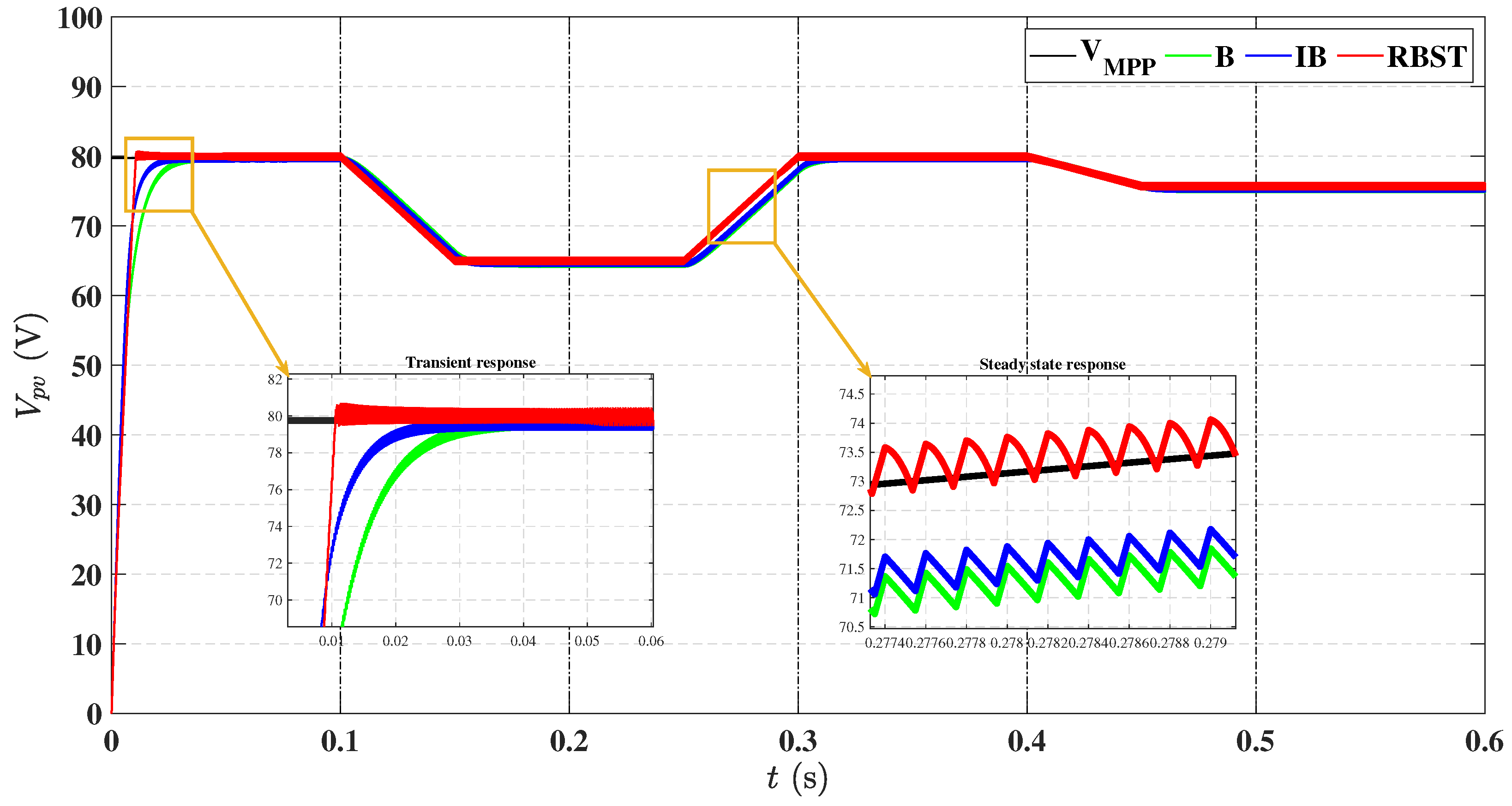
Figure 12 presents the output voltage, V p v , response of the PV array. From the zoomed-in view, it is evident that the proposed controller achieves reference tracking, V M P P , in approximately 0.01   s , outperforming both B and IB controllers in terms of rise time. This confirms the superior transient performance and faster dynamic convergence of the RBST method. Moreover, during the irradiance–temperature ramp transitions at 0.1   s , 0.25   s , and 0.4   s , the proposed controller maintains excellent tracking of the maximum power point voltage, V M P P , while the B and IB controllers exhibit persistent steady-state tracking error, indicating their limited adaptability under gradual environmental fluctuations.
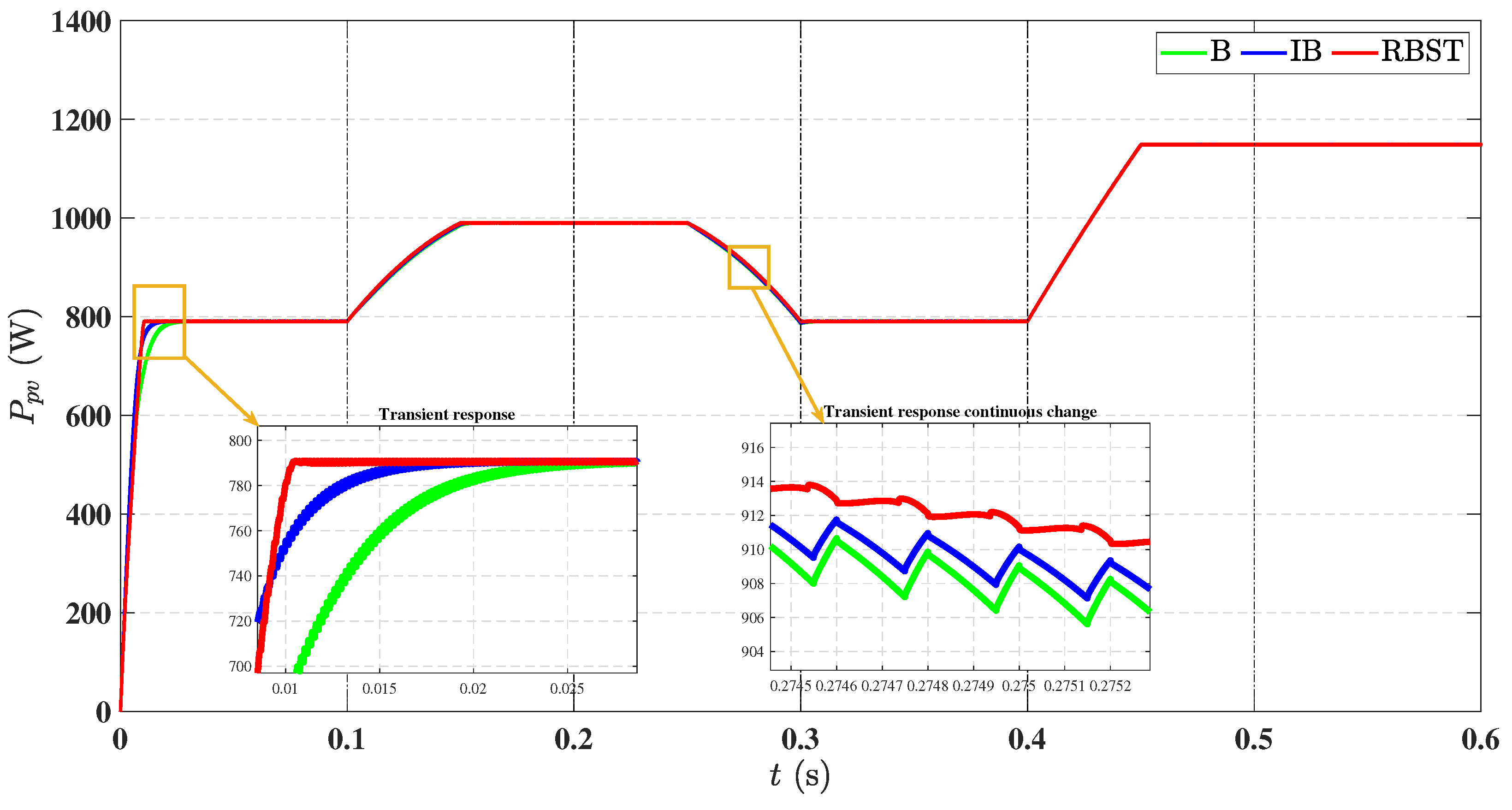
Figure 13 illustrates the corresponding PV array output power, P p v . The RBST controller once again demonstrates rapid convergence toward maximum power output, thereby ensuring efficient MPPT operation throughout the test period. The zoomed-in view confirms its superior transient power acquisition capability compared to its counterparts.
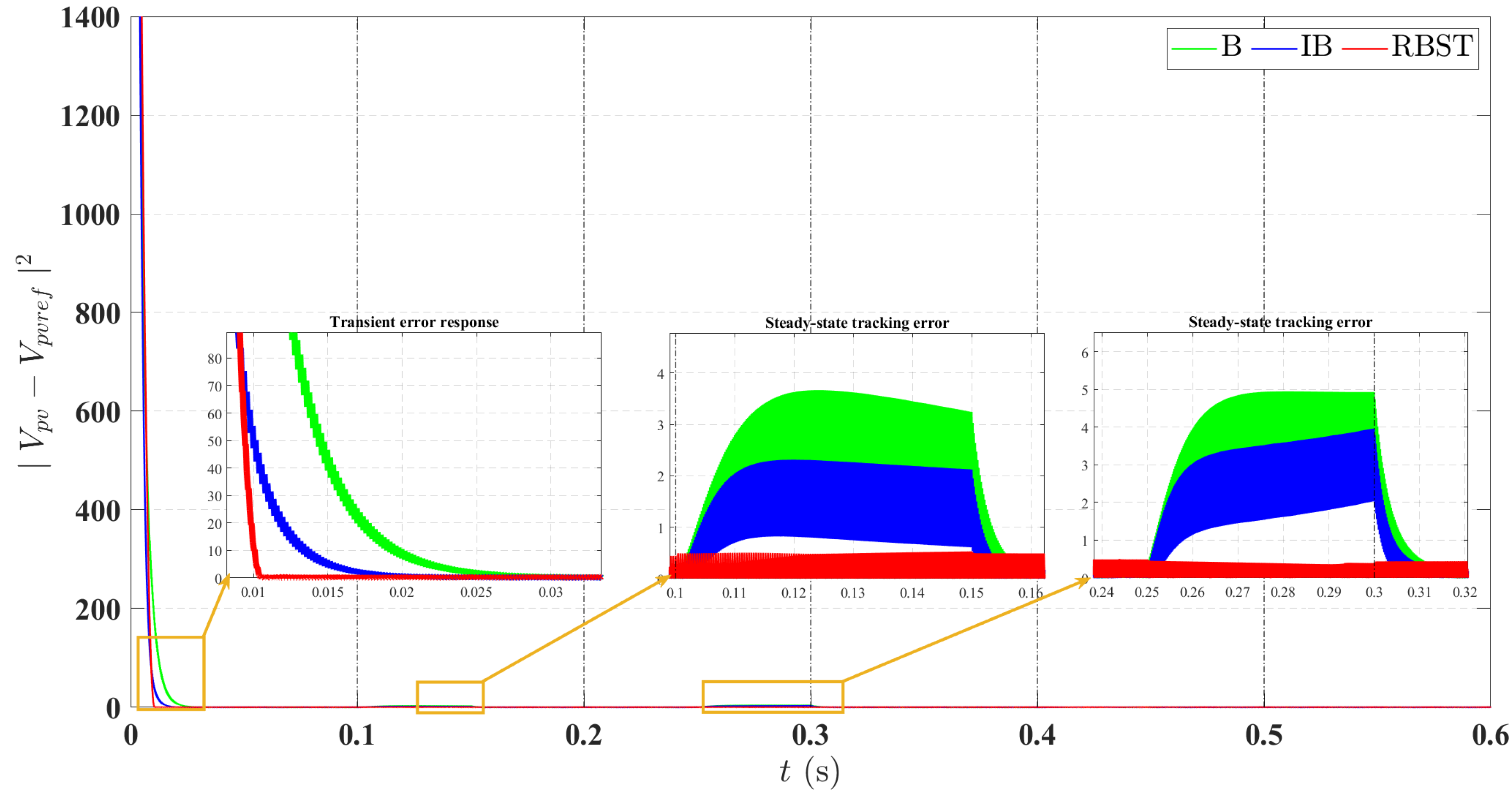
Tracking error performance is quantitatively validated in Figure 14, which plots the squared voltage tracking error, V p v V M P P 2 . The RBST controller yields the lowest error in both transient and steady-state phases. It is observed that during ramp variations at 0.1   s and 0.25   s , the B and IB controllers exhibit comparatively higher tracking error, confirming their limited adaptation to environmental changes. Conversely, the proposed RBST technique maintains minimal error, reflecting its robustness and high precision.
Furthermore, the proposed RBST-based MPPT approach consistently sustains power extraction efficiency above 99%, as shown in Table 6, outperforming the other methods under dynamic conditions. This confirms the effectiveness of the RBST controller in achieving reliable maximum power tracking even under fluctuating irradiance and temperature.

6.2. Sudden Step Changes in Irradiance and Temperature

In practical PV applications, abrupt changes in irradiance and temperature are commonly caused by rapid cloud movements or sudden atmospheric fluctuations. To validate the transient and steady-state tracking performance of the designed RBST-based MPPT controller under such abrupt conditions, a step-type irradiance and temperature profile is applied, as shown in Table 7. The steps are introduced at regular intervals of 0.1 s, emulating abrupt environmental transitions.
The dynamic voltage response of the PV array subjected to step changes is depicted in Figure 15. The zoomed-in views clearly demonstrate that the RBST controller exhibits superior transient performance by rapidly tracking the maximum power point voltage, V M P P , within 0.01 s after each disturbance. This validates a significantly faster rise time and higher responsiveness compared to the B and IB methods. Furthermore, the RBST technique remains closely aligned with the reference V M P P after each step input, while the other two techniques, B and IB, exhibit larger tracking delays and settling lags.
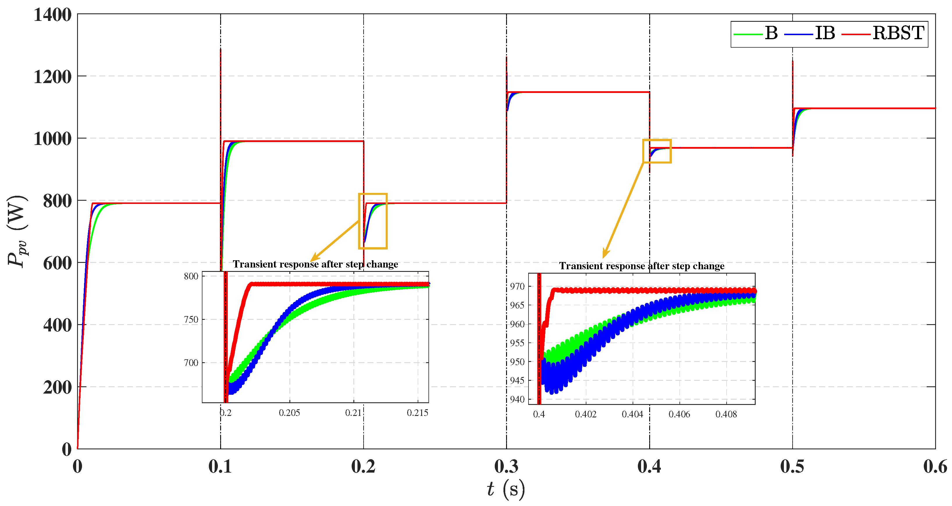
Figure 16 presents the comparative plot for the PV array output power under the same operating conditions. It can be seen that the RBST-based MPPT controller exhibits rapid recovery and minimal deviation from the MPP after each step perturbation, effectively validating its robustness in rejecting abrupt variations and maintaining optimal power extraction. The zoomed-in view of Figure 16 further confirms that the B and IB controllers suffer from slower rise times and prolonged settling during and after sudden disturbances.
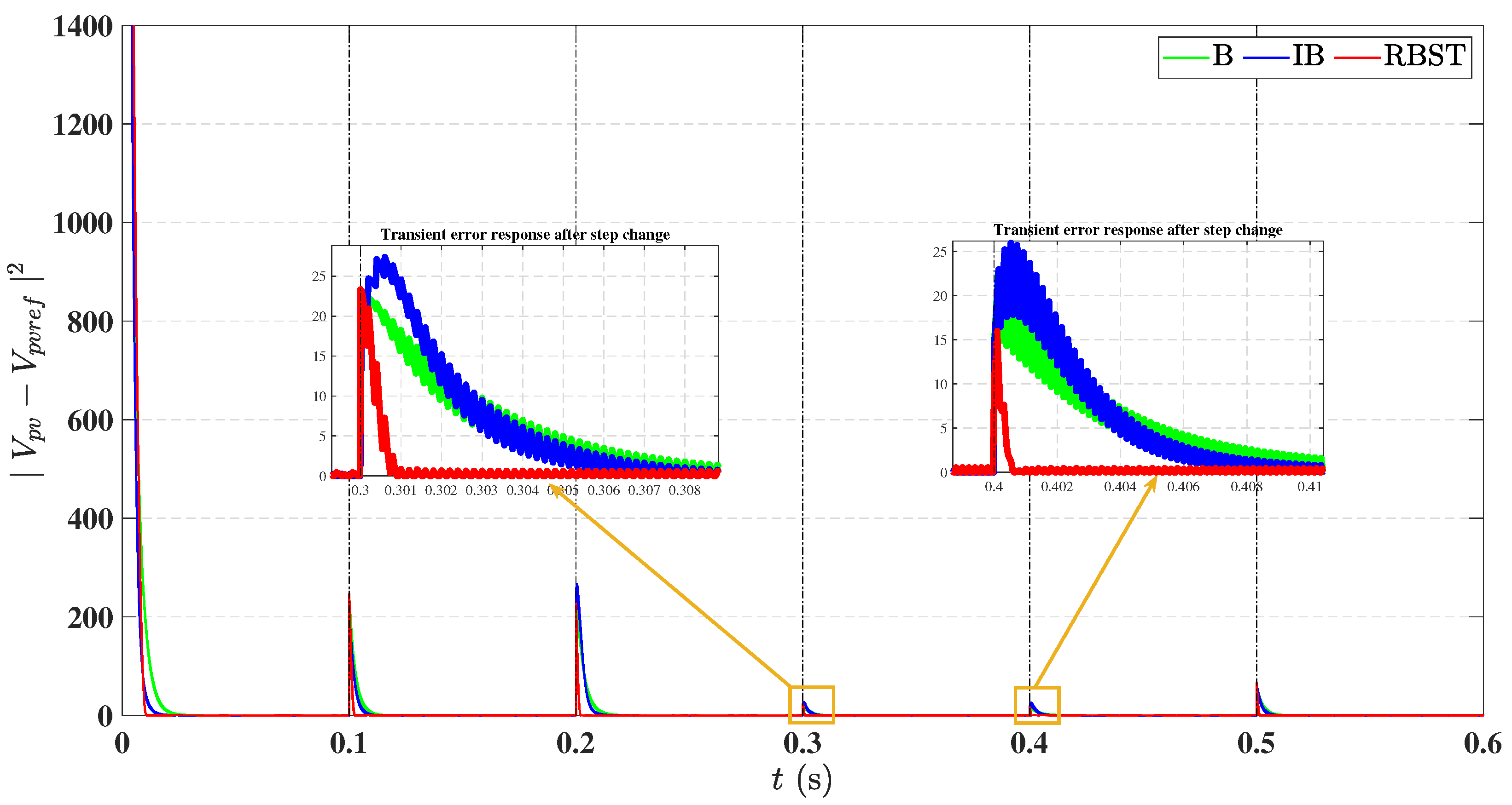
To validate the accuracy of voltage regulation, Figure 17 illustrates the squared voltage tracking error, V p v V M P P 2 . The error profiles show that the RBST-based MPPT technique significantly minimizes the error magnitude during both transient and steady-state conditions. The zoomed-in view of Figure 17 demonstrates its superior disturbance rejection and precise control action, even under fast-switching meteorological conditions.
Overall, the RBST method maintained power tracking efficiency above 99% throughout the step changes, as depicted in Table 6, outperforming both B and IB techniques. These findings highlight the robustness and adaptability of the proposed RBST-based MPPT controller in real-world PV operational scenarios involving abrupt meteorological transitions.

6.3. Performance Comparison Under Partial Shading Conditions

The task of MPP tracking becomes significantly more challenging when the entire PV array does not receive uniform irradiance—a condition commonly referred to as partial shading. Such scenarios arise due to obstructions like nearby buildings, poles, trees, or fast-moving clouds casting shadows on different sections of a PV module. Under shaded conditions, the affected modules operate as resistive loads, potentially initiating hot-spot issues. To mitigate these effects, bypass diodes are integrated within modules to maintain current continuity and provide thermal protection. Under uniform irradiance, these diodes remain reverse-biased; however, during shading, they become forward-biased, altering the module’s I ˘ V characteristics and introducing multiple local peaks in the global P ˘ V curve. This inherently leads to multi-modal power surfaces, which demand robust and intelligent MPPT control to avoid convergence at local maxima.
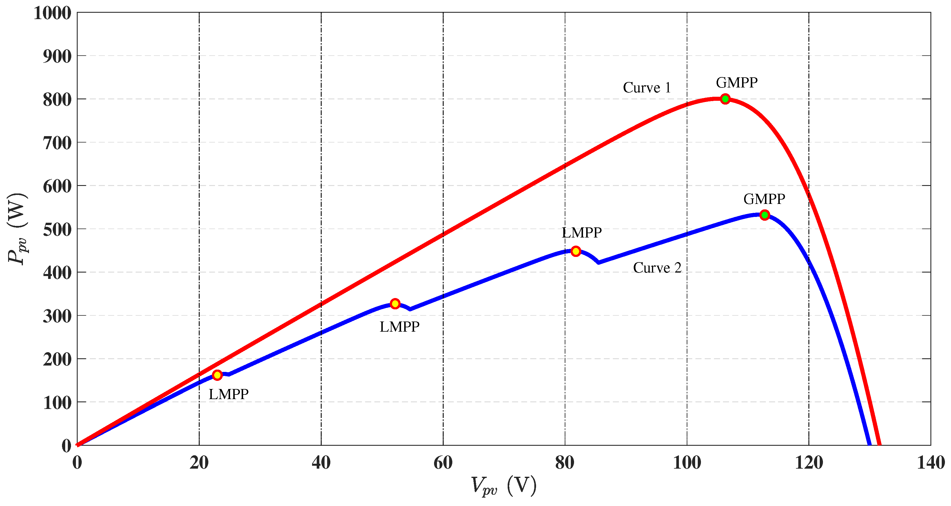
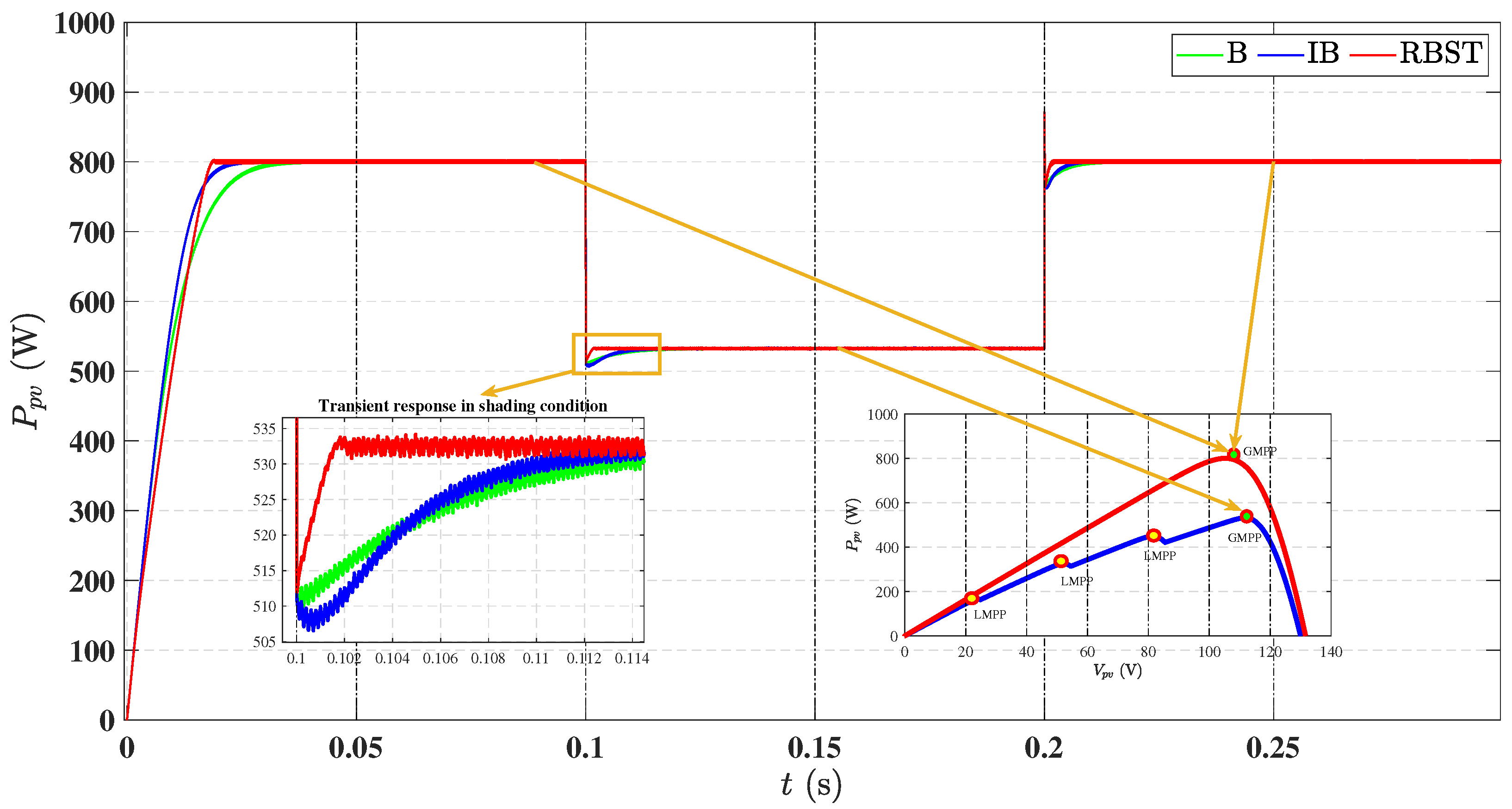
To validate the capability of the proposed RBST-based MPPT controller in navigating such complex power landscapes, a simulation is performed with four series-connected PV modules (A–D), each following the specifications listed in Table 1. Initially, all modules receive uniform irradiance of 1000 W /m2, resulting in a single global MPP at 800.60 W, as illustrated by curve 1 in Figure 18. After 0.1   s , a non-uniform irradiance pattern is introduced: modules A, B, C, and D receive 600 W /m2, 700 W /m2, 800 W /m2, and 900 W /m2, respectively. This condition generates multiple peaks in the P ˘ V curve, as shown in curve 2 of Figure 18, with corresponding local maxima at 164.50   W /m2, 324.60   W /m2, 449.10   W /m2, and 532.60   W /m2. As a result, the operating point must transition from curve 1 to curve 2, requiring the MPPT controller to bypass local peaks and accurately converge to the global MPP (i.e., GMPP). At 0.2   s , uniform irradiance of 1000 W /m2 is re-applied to all modules, restoring the single-peak scenario of curve 1. This shift enforces another real-time transition in the power surface, allowing evaluation of the controller’s convergence agility and resilience to partial shading dynamics. This profile directly challenges the controller’s ability to escape local optima and relocate the global MPP during both the entry into and recovery from partial shading conditions.
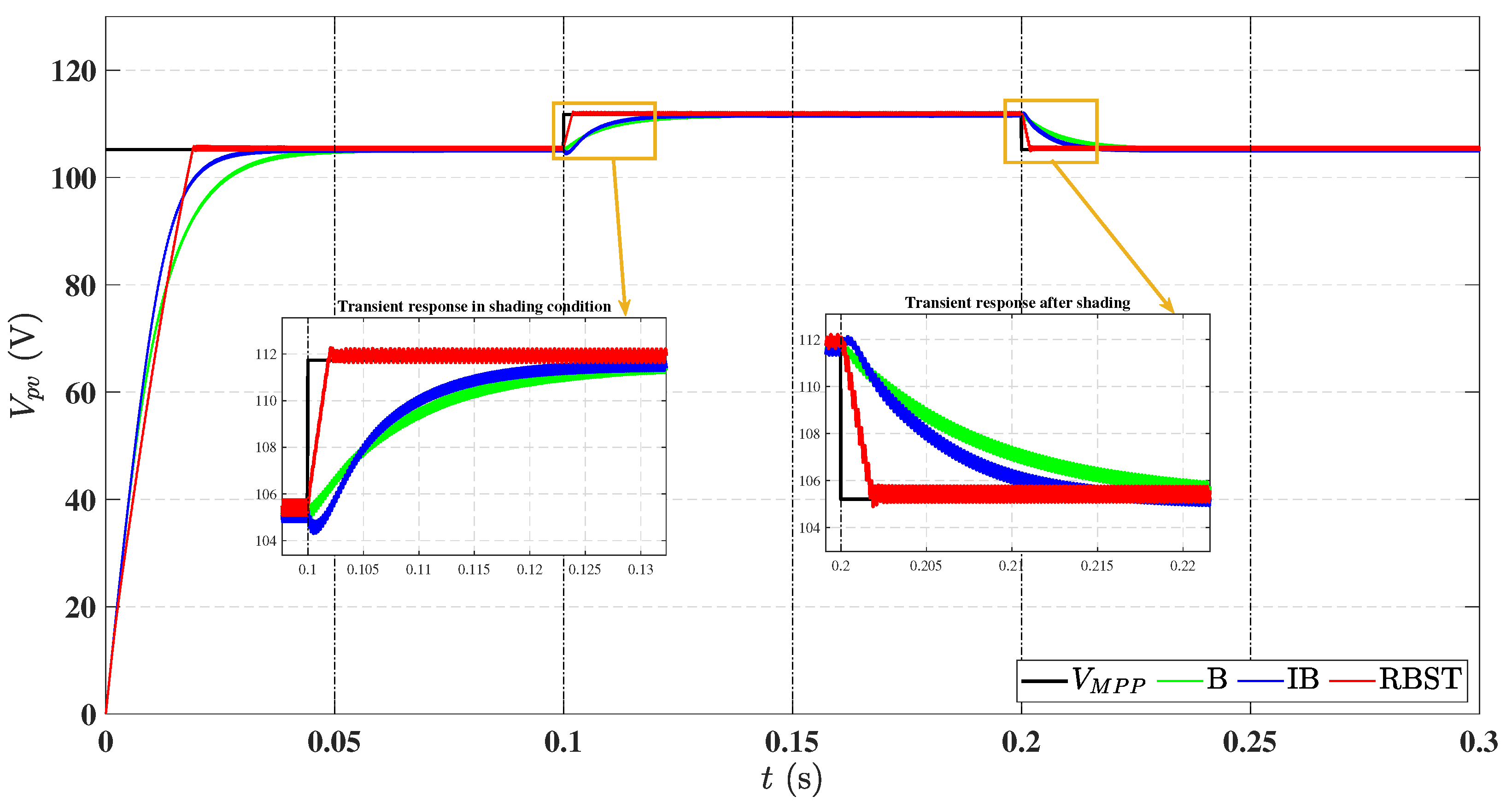
Figure 19 illustrates the dynamic voltage response of the PV array under partial shading conditions. At t =   0.1   s , when the array is subjected to non-uniform irradiance, all three MPPT controllers successfully bypass local maxima and converge toward the global MPP, demonstrating resilience against local peak entrapment. However, the transient response characteristics differ significantly. The proposed RBST controller exhibits the fastest convergence to V M P P , with minimal voltage deviation and no observable undershoot, highlighting its superior disturbance rejection and nonlinear tracking capability. In contrast, the IB controller shows a noticeable undershoot immediately after the shading transition, indicating sensitivity to irradiance imbalance and a slower recovery profile. The B controller, while able to track the global MPP, responds with a comparatively sluggish voltage rise and larger transient deviation, confirming its limited adaptability under shaded nonlinear operating surfaces. At t =   0.2   s , when uniform irradiance is restored, the RBST controller again achieves rapid re-alignment with the MPP, confirming its robustness in dynamically shifting power landscapes.
Figure 20 depicts the PV array output power during partial shading. At t = 0.1   s , the RBST controller rapidly tracks the global MPP despite the presence of multiple local peaks, delivering higher power output with minimal oscillation. In comparison, both IB and B controllers show delayed convergence and lower power levels. At t = 0.2   s , when uniform irradiance is restored, RBST once again demonstrates faster resettling and consistent maximum power delivery. The squared voltage tracking error V p v V M P P 2 is shown in Figure 21. The RBST controller maintains the lowest error during both transitions, confirming superior precision and robustness. In contrast, the B and IB controllers exhibit higher and prolonged tracking errors, indicating slower adaptation and reduced accuracy under partial shading disturbances.
Furthermore, the RBST-based MPPT controller achieves excellent power tracking efficiency under partial shading conditions, maintaining performance above 99%. This high efficiency, coupled with reduced tracking error, highlights the controller’s robustness and accuracy. A comprehensive comparison of all MPPT techniques across the three evaluated scenarios is presented in Table 6, validating the overall superiority of the proposed RBST technique.

7. Conclusions

This research article presents a nonlinear, hybrid, and highly efficient MPPT control strategy based on the Robust Backstepping Super-Twisting (RBST) approach for a standalone photovoltaic system. The system architecture comprises a PV array, a non-inverting buck–boost DC–DC converter, and a purely resistive load, with the converter serving as the power electronic interface between the PV source and the load. System stability is ensured using Lyapunov-based analysis. The proposed RBST controller operates in a dual-loop configuration: the first loop utilizes an Adaptive Neuro-Fuzzy Inference System to compute an offline reference voltage corresponding to peak power, while the second loop employs the RBST algorithm to drive the system to this reference by continuously modulating the converter’s duty cycle.
The performance of the RBST-based MPPT scheme is verified through MATLAB/Simulink simulations under three test scenarios: continuously varying irradiance and temperature, sudden step changes in environmental conditions, and partial shading. The comparative evaluation confirms that the RBST controller outperforms both classical backstepping and integral backstepping techniques by achieving faster convergence to the maximum power point, shorter rise and settling times, lower tracking error, enhanced voltage stability, and quick adaptation to changing environmental conditions. Additionally, the RBST controller consistently maintains a tracking efficiency above 99% across all operating profiles.
The results demonstrate that the RBST method offers accurate, stable, and high-performance MPPT operation under dynamic and uncertain environmental conditions. Moreover, this work contributes to a broader ongoing research effort on PV plant development and monitoring, in which it represents the efficiency-optimization stage that can be integrated with geospatial decision support, environmental monitoring, and advanced control within prototype systems for enhanced PV performance.

Author Contributions

Conceptualization, K.A. and S.U.; methodology, K.A.; software, K.A.; validation, K.A., S.U. and E.C.; formal analysis, K.A.; investigation, K.A.; resources, S.U.; data curation, K.A.; writing—original draft preparation, K.A.; writing—review and editing, K.A., S.U. and E.C.; visualization, K.A.; supervision, S.U. and E.C.; project administration, S.U. and E.C. All authors have read and agreed to the published version of the manuscript.

Funding

This research received no external funding.

Data Availability Statement

The data presented in this study are available on request from the corresponding author.

Conflicts of Interest

The authors declare no conflicts of interest.

Abbreviations

The following abbreviations are used in this manuscript:
ACAlternating Current
ANFISAdaptive Neuro-Fuzzy Inference System
DCDirect Current
GISGeographical Information System
LSTLand Surface Temperature
MPPMaximum Power Point
MPPTMaximum Power Point Tracking
NIBBPCNon-inverting Buck–Boost Power Converter
OCVOpen-Circuit Voltage
P&OPerturb & Observe
PVPhotovoltaic
PWMPulse Width Modulation
RESsRenewable Energy Sources
RBSTRobust Backstepping Super-Twisting
SCCShort-Circuit Current
SMCSliding Mode Control

References

  1. Ahmad, F.F.; Ghenai, C.; Hamid, A.K.; Bettayeb, M. Application of sliding mode control for maximum power point tracking of solar photovoltaic systems: A comprehensive review. Annu. Rev. Control 2020, 49, 173–196. [Google Scholar] [CrossRef]
  2. Hadj Salah, Z.B.; Krim, S.; Hajjaji, M.A.; Alshammari, B.M.; Alqunun, K.; Alzamil, A.; Guesmi, T. A new efficient cuckoo search MPPT algorithm based on a super-twisting sliding mode controller for partially shaded standalone photovoltaic system. Sustainability 2023, 15, 9753. [Google Scholar] [CrossRef]
  3. Ali, K.; Khan, L.; Khan, Q.; Ullah, S.; Ahmad, S.; Mumtaz, S.; Karam, F.W.; Naghmash. Robust integral backstepping based nonlinear MPPT control for a PV system. Energies 2019, 12, 3180. [Google Scholar] [CrossRef]
  4. Harrison, A.; Nguimfack-Ndongmo, J.D.D.; Alombah, N.H.; Kazé, C.V.A.; Kuate-Fochie, R.; Asoh, D.A.; Nfah, E.M. Robust nonlinear MPPT controller for PV energy systems using PSO-based integral backstepping and artificial neural network techniques. Int. J. Dyn. Control 2024, 12, 1598–1615. [Google Scholar] [CrossRef]
  5. Ali, K.; Khan, Q.; Ullah, S.; Khan, I.; Khan, L. Nonlinear robust integral backstepping based MPPT control for stand-alone photovoltaic system. PLoS ONE 2020, 15, e0231749. [Google Scholar] [CrossRef]
  6. Ali, K.; Khan, Q.; Khan, L.; Khan, U.A.; Ullah, A. MPPT for photovoltaic system using non-linear hybrid robust integral backstepping controller. In Proceedings of the 2020 3rd International Conference on Computing, Mathematics and Engineering Technologies (iCoMET), Sukkur, Pakistan, 29–30 January 2020; IEEE: Piscataway, NJ, USA, 2020; pp. 1–6. [Google Scholar]
  7. Reisi, A.R.; Moradi, M.H.; Jamasb, S. Classification and comparison of maximum power point tracking techniques for photovoltaic system: A review. Renew. Sustain. Energy Rev. 2013, 19, 433–443. [Google Scholar] [CrossRef]
  8. Bhatnagar, P.; Nema, R.K. Maximum power point tracking control techniques: State-of-the-art in photovoltaic applications. Renew. Sustain. Energy Rev. 2013, 23, 224–241. [Google Scholar] [CrossRef]
  9. Lapkitticharoenchai, Y.; Jangwanitlert, A. Lookup table technique by using irradiation intensity and duty cycle for faster MPPT application. In Proceedings of the 2023 8th International Conference on Business and Industrial Research (ICBIR), Bangkok, Thailand, 18–19 May 2023; pp. 1–5. [Google Scholar]
  10. González-Castaño, C.; Lorente-Leyva, L.L.; Muñoz, J.; Restrepo, C.; Peluffo-Ordóñez, D.H. An MPPT strategy based on a surface-based polynomial fitting for solar photovoltaic systems using real-time hardware. Electronics 2021, 10, 206. [Google Scholar] [CrossRef]
  11. Mazumdar, D.; Sain, C.; Biswas, P.K.; Sanjeevikumar, P.; Khan, B. Overview of solar photovoltaic MPPT methods: A state of the art on conventional and artificial intelligence control techniques. Int. Trans. Electr. Energy Syst. 2024, 2024, 8363342. [Google Scholar] [CrossRef]
  12. Kumar, V.; Bindal, R.K. MPPT technique used with perturb and observe to enhance the efficiency of a photovoltaic system. Mater. Today Proc. 2022, 69, A6–A11. [Google Scholar] [CrossRef]
  13. Ali, Z.; Abbas, S.Z.; Mahmood, A.; Ali, S.W.; Javed, S.B.; Su, C.L. A study of a generalized photovoltaic system with MPPT using perturb and observer algorithms under varying conditions. Energies 2023, 16, 3638. [Google Scholar] [CrossRef]
  14. Elgendy, M.A.; Zahawi, B.; Atkinson, D.J. Assessment of the incremental conductance maximum power point tracking algorithm. IEEE Trans. Sustain. Energy 2012, 4, 108–117. [Google Scholar] [CrossRef]
  15. Moradi, M.H.; Reisi, A.R. A hybrid maximum power point tracking method for photovoltaic systems. Sol. Energy 2011, 85, 2965–2976. [Google Scholar] [CrossRef]
  16. Yang, C.Y.; Hsieh, C.Y.; Feng, F.K.; Chen, K.H. Highly efficient analog maximum power point tracking (AMPPT) in a photovoltaic system. IEEE Trans. Circuits Syst. I Regul. Pap. 2012, 59, 1546–1556. [Google Scholar] [CrossRef]
  17. Armghan, H.; Ahmad, I.; Armghan, A.; Khan, S.; Arsalan, M. Backstepping based non-linear control for maximum power point tracking in photovoltaic system. Sol. Energy 2018, 159, 134–141. [Google Scholar] [CrossRef]
  18. Arsalan, M.; Iftikhar, R.; Ahmad, I.; Hasan, A.; Sabahat, K.; Javeria, A. MPPT for photovoltaic system using nonlinear backstepping controller with integral action. Sol. Energy 2018, 170, 192–200. [Google Scholar] [CrossRef]
  19. Chiu, C.S.; Ouyang, Y.L.; Ku, C.Y. Terminal sliding mode control for maximum power point tracking of photovoltaic power generation systems. Sol. Energy 2012, 86, 2986–2995. [Google Scholar] [CrossRef]
  20. Koofigar, H.R. Adaptive robust maximum power point tracking control for perturbed photovoltaic systems with output voltage estimation. ISA Trans. 2016, 60, 285–293. [Google Scholar] [CrossRef]
  21. Pradhan, R.; Subudhi, B. Double integral sliding mode MPPT control of a photovoltaic system. IEEE Trans. Control Syst. Technol. 2015, 24, 285–292. [Google Scholar] [CrossRef]
  22. Ghaffarzadeh, N.; Bijani, S. Dual surface sliding mode controller for photovoltaic systems enhanced by a ripple domain search maximum power point tracking algorithm for fast changing environmental conditions. IET Renew. Power Gener. 2016, 10, 611–622. [Google Scholar] [CrossRef]
  23. Zhang, L.; Tao, R.; Bai, J.; Zeng, D. An Improved Sliding Mode Model Reference Adaptive System Observer for PMSM Applications. Expert Syst. Appl. 2024, 250, 123907. [Google Scholar] [CrossRef]
  24. Zhang, L.; Li, X. Sliding Mode Control of Surface-Mounted Permanent Magnet Synchronous Motor Based on Composite Adaptive Reaching Law. In Proceedings of the 2025 IEEE International Conference on Predictive Control of Electrical Drives and Power Electronics (PRECEDE), Jinan, China, 15–17 August 2025; pp. 1–5. [Google Scholar]
  25. Clementini, E.; Patrizi, R.; Santic, M.; Villante, C. A GeoSpatial Information System for Photovoltaic Plants Development and Monitoring. Int. Arch. Photogramm. Remote Sens. Spat. Inf. Sci. 2024, 48, 45–50. [Google Scholar] [CrossRef]
  26. Ali, K.; Clementini, E.; Patrizi, R.; Santic, M.; Villante, C. CNN-Based Downscaling of Land Surface Temperature and Scaling Effect Analysis Using Multi-Sensor Satellite Data: A Case Study in L’Aquila, Italy. In Proceedings of the GeoVisions2025: Symposium on GeoSpatial Technologies: Visions and Horizons, Çanakkale, Turkey, 8–10 October 2025. [Google Scholar]
  27. Villalva, M.G.; Gazoli, J.R.; Filho, E.R. Comprehensive approach to modeling and simulation of photovoltaic arrays. IEEE Trans. Power Electron. 2009, 24, 1198–1208. [Google Scholar] [CrossRef]
  28. Ali, K.; Khan, L.; Khan, Q.; Ullah, S.; Ali, N. Neurofuzzy robust backstepping based MPPT control for photovoltaic system. Turk. J. Electr. Eng. Comput. Sci. 2021, 29, 421–436. [Google Scholar] [CrossRef]
  29. Kim, I.-S. Robust maximum power point tracker using sliding mode controller for the three-phase grid-connected photovoltaic system. Sol. Energy 2007, 81, 405–414. [Google Scholar] [CrossRef]
  30. Kim, I.-S. Sliding mode controller for the single-phase grid-connected photovoltaic system. Appl. Energy 2006, 83, 1101–1115. [Google Scholar] [CrossRef]
  31. Rashid, M.H. Power Electronics Handbook: Devices, Circuits and Applications; Elsevier: Oxford, UK, 2010. [Google Scholar]
  32. Erickson, R.W.; Maksimović, D. Fundamentals of Power Electronics; Springer Science & Business Media: New York, NY, USA, 2007. [Google Scholar]
  33. Almasi, O.N.; Fereshtehpoor, V.; Khooban, M.H.; Blaabjerg, F. Analysis, control and design of a non-inverting buck-boost converter: A bump-less two-level T–S fuzzy PI control. ISA Trans. 2017, 67, 515–527. [Google Scholar] [CrossRef]
  34. Chen, J.; Maksimović, D.; Erickson, R.W. Analysis and design of a low-stress buck-boost converter in universal-input PFC applications. IEEE Trans. Power Electron. 2006, 21, 320–329. [Google Scholar] [CrossRef]
  35. Siddique, N.; Adeli, H. Computational Intelligence: Synergies of Fuzzy Logic, Neural Networks and Evolutionary Computing; John Wiley & Sons: Hoboken, NJ, USA, 2013. [Google Scholar]
  36. Krstić, M.; Kanellakopoulos, I.; Kokotović, P.V. Nonlinear and Adaptive Control Design; John Wiley & Sons: Hoboken, NJ, USA, 1995. [Google Scholar]
  37. Krstić, M.; Smyshlyaev, A. Boundary Control of PDEs: A Course on Backstepping Designs; Society for Industrial and Applied Mathematics (SIAM): Philadelphia, PA, USA, 2008. [Google Scholar]
  38. Slotine, J.-J.; Li, W. Applied Nonlinear Control; Prentice Hall: Englewood Cliffs, NJ, USA, 1991. [Google Scholar]
  39. Marquez, H.J. Nonlinear Control Systems: Analysis and Design; John Wiley & Sons: Hoboken, NJ, USA, 2003. [Google Scholar]
  40. Li, S.; Yu, X.; Fridman, L.; Man, Z.; Wang, X. Advances in Variable Structure Systems and Sliding Mode Control—Theory and Applications; Springer International Publishing: Cham, Switzerland, 2017. [Google Scholar]
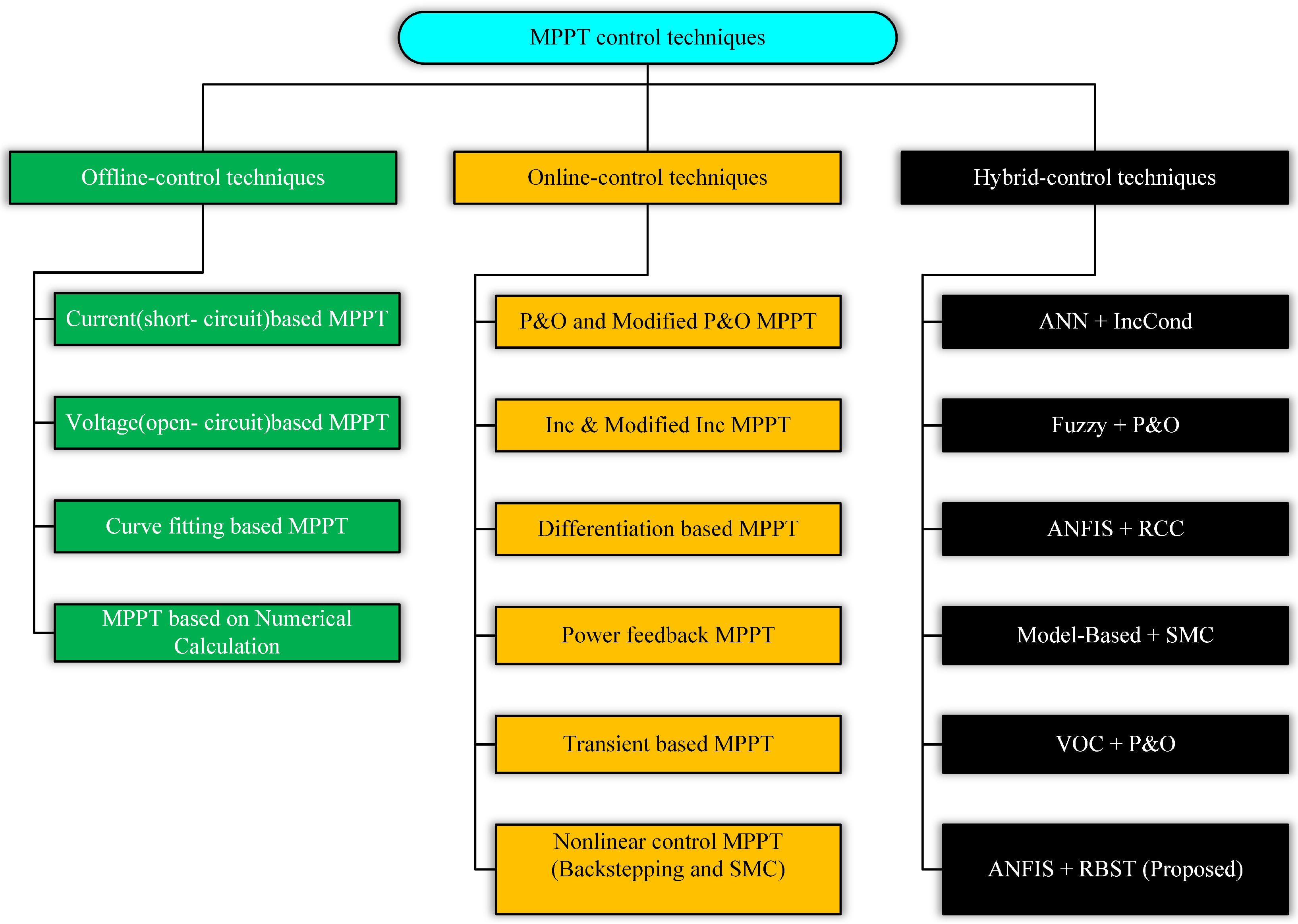
Figure 1. Classification of MPPT techniques into offline, online, and hybrid categories.
Energies 18 05134 g001
Figure 2. Single-diode-based equivalent electric circuit of a practical PV cell.
Energies 18 05134 g002
Figure 3. Single-diode-based equivalent electric circuit of a practical PV array.
Energies 18 05134 g003
Figure 4. I vs. V characteristics of the Kyocera Solar KC200GT module.
Energies 18 05134 g004
Figure 5. P vs. V characteristics of the Kyocera Solar KC200GT module.
Energies 18 05134 g005
Figure 6. Equivalent electric circuit of the NIBBPC with input and output.
Energies 18 05134 g006
Figure 7. Equivalent electric circuit of the NIBBPC under switching interval 1 ( S 1 , S 2 : ON, while D 1 , D 2 : OFF).
Energies 18 05134 g007
Figure 8. Equivalent electric circuit of the NIBBPC under switching interval 2 ( S 1 , S 2 : OFF, while D 1 , D 2 : ON).
Energies 18 05134 g008
Figure 9. ANFIS generated 3-D surface between two input variables (T and G) and one output variable ( V M P P ).
Energies 18 05134 g009
Figure 10. Block diagram of the proposed Robust Backstepping Super-Twisting (RBST)-based MPPT control scheme for a PV system.
Energies 18 05134 g010
Figure 11. Temperature and irradiance profiles for continuously varying conditions.
Energies 18 05134 g011
Figure 12. Comparison of MPP voltage tracking by RBST, IB, and B controllers under continuously varying irradiance and temperature conditions.
Energies 18 05134 g012
Figure 13. MPP power tracking comparison of RBST, IB, and B controllers under continuously varying irradiance and temperature conditions.
Energies 18 05134 g013
Figure 14. Comparison of squared voltage tracking error for RBST, IB, and B controllers under continuously varying irradiance and temperature conditions.
Energies 18 05134 g014
Figure 15. Comparison of MPP voltage tracking by RBST, IB, and B controllers under step changes in irradiance and temperature.
Energies 18 05134 g015
Figure 16. Comparison of MPP power tracking by RBST, IB, and B controllers under step changes in irradiance and temperature.
Energies 18 05134 g016
Figure 17. Comparison of squared voltage tracking error for RBST, IB, and B controllers under step changes in irradiance and temperature.
Energies 18 05134 g017
Figure 18. P ˘ V curve for MPP tracking under partial shading conditions.
Energies 18 05134 g018
Figure 19. MPP voltage tracking comparison of RBST, IB, and B controllers under partial shading conditions.
Energies 18 05134 g019
Figure 20. MPP power tracking comparison of RBST, IB, and B controllers under partial shading conditions.
Energies 18 05134 g020
Figure 21. Squared voltage tracking error comparison of RBST, IB, and B controllers under partial shading conditions.
Energies 18 05134 g021
Table 1. Electrical characteristics of Kyocera Solar KC200GT module under STC.
S. No.ParametersValues
1Number of series-connected cells per module, N s 54
2Number of series-connected modules per string1
3Number of parallel-connected strings per array, N p 1
4Maximum power, P M P P 200.143 W
5Voltage @ maximum power, V M P P 26.30 V
6Current @ maximum power, I M P P 7.61 V
7Open-circuit voltage, V O C 32.90 V
8Short-circuit current, I S C 8.21 A
9Light-generated current, I p h 8.2288 A
10Diode saturation current, I 0 2.3246 × 10 6
11Temperature coefficient of V O C −0.35502 % / °C
12Temperature coefficient of I S C 0.06 % / °C
13Shunt resistance, R p 150.6921 Ω
14Series resistance, R s 0.34483 Ω
15Diode ideality factor, α 0.97736
Table 2. Different operating modes of the NIBBPC.
S. No.Operating Mode Name S 1 (During T s ) S 2 (During T s )
1BuckSwitched ON and OFFOFF (Continuously)
2BoostON (Continuously)Switched ON and OFF
3Buck–BoostSwitched ON and OFFSwitched ON and OFF
Table 3. Design parameters of the NIBBPC.
S. No.ParametersValues
1Input capacitor, C 1 1 m F
2Output capacitor, C 2 48 μ F
3Inductor, L20 m H
4Load resistance, R L 50 Ω
Table 4. Various training parameters of the ANFIS for V M P P learning.
S. No.ParametersDescription
1Number of inputs to ANFIS2
2Number of outputs of ANFIS1
3ANFIS type chosenTSK (Takagi–Sugeno–Kang)
4Membership function type chosenTriangular (trimf)
5No. of membership functions chosen for each input3
6Error tolerance for ANFIS training0
7Number of epochs chosen for ANFIS training10
8Minimal training RMSE0.01348
Table 5. The design parameters of the proposed RBST-based MPPT control technique.
S. No.ParametersValues
1Constant, κ 1 12
2Constant, κ 2 4500
3Constant, κ 3 5100
4Constant, κ 4 70
5Constant, κ 5 0.15
6Constant, κ 6 0.7
Table 6. Summary of MPPT controller performance metrics evaluated in Section 4.
MetricBackstepping (B)Integral Backstepping (IB)RBST (Proposed)
Rise Time (s)0.0540.0380.018
Mean SSE (V)0.70400.63710.3015
RMSE (V)1.45591.44120.5718
Steady-State Error (%)0.670.610.29
Efficiency (%)98.0198.1699.61
Table 7. Simulated conditions for step change in irradiance and temperature.
Time (s)00.10.20.30.40.5
T (°C)256525352545
G ( W / m 2)650100065010008001000
P M P P (W)79099079011499691096
Disclaimer/Publisher’s Note: The statements, opinions and data contained in all publications are solely those of the individual author(s) and contributor(s) and not of MDPI and/or the editor(s). MDPI and/or the editor(s) disclaim responsibility for any injury to people or property resulting from any ideas, methods, instructions or products referred to in the content.