1. Introduction
Hydropower is set to play a prominent role in many of the world’s major electrical power grids in the 21st century. It also contributes almost a fifth of global electricity generation and more than half of global renewable electricity generation [
1]. In this view, Ethiopia is often described as the water tower of northeastern Africa, with 45,000 MW of installable hydropower potential. In recent years, hydropower development has become the focus of attention in this country. Exploiting this resource would bring various social, environmental, and economic advantages to the country; most importantly, it would improve energy poverty and allow the country to strengthen its climate-resilient economic strategy. However, a lack of access to modern energy remains a chronic problem, especially in rural areas. Rural electrification through national grid extension is expensive and difficult, as more than 80% of the population lives in scattered rural village settings. On the other hand, the average annual potential to exploit water resources for off-grid applications through small-scale hydroelectric development is about 20 TWh/year [
2]. This potential can contribute to the country’s short–medium-term off-grid electrification strategy [
3].
Like in other developing countries, rural electrification is a priority development agenda in Ethiopia. However, few appropriate off-grid solutions have been implemented to date [
2]. In 2017, the country launched a “light to all” strategy to provide access to about seven million rural and deep rural households without national grid connectivity (about 35% of the population) and achieve universal access by 2025. To support this strategy, there was a plan to build more than eighty-five small and micro-hydropower plants. However, complete failure of this plan has occurred due to the implementation and unavailability of local technology.
Small and micro-hydropower plants are known for their ability to supply electricity in rural areas with environmentally sound, affordable, and adequate energy production. This would lead to increased employment opportunities, poverty alleviation, improvements in local living and cultural standards, environmental protection, and economic development in remote areas. In addition, major constraints associated with large hydro projects can usually be avoided. Moreover, small hydropower (SHP) schemes have short lifecycles and low investment costs per kW of installed capacity. It is also possible to size a system to meet a specific power demand based on the resource potential of a site and the available financing.
Ethiopia has a high installed capacity of standalone SHP plants. This capacity is estimated to be about 10% of the total potential (1500–3000 MW), though this might vary with seasonal rainfall and increased small-scale irrigation work [
2]. The motivation for this paper is to demonstrate an ongoing project of small hydropower development from scratch using the local capacity with the objective to alleviate the lack of local technology that can be adopted, expanded, and scaled up by the government and community.
This paper presents findings from an applied research project on off-grid electrification, with a primary focus on optimized design and development of crossflow turbines, i.e., a novel approach within the Ethiopian context. This paper is organized in five sections.
Section 1 provides an introduction and background information, and
Section 2 details the employed methodology. The design of the crossflow turbine is presented in
Section 3, followed by the results and discussion in
Section 4.
Section 5 covers the manufacturing process, and
Section 6 provides conclusions and recommendations.
1.1. Site Description: Amentila Small Hydropower Plant
This paper presents only the turbine part of an SHP plant with a 125 kW generating capacity that is under construction for the rural community of Amentila Village. The power plant is found in the southeastern zone of Tigray (Northern Ethiopia), Enderta district, Amentila and Lihama villages and covers about 31.5 km
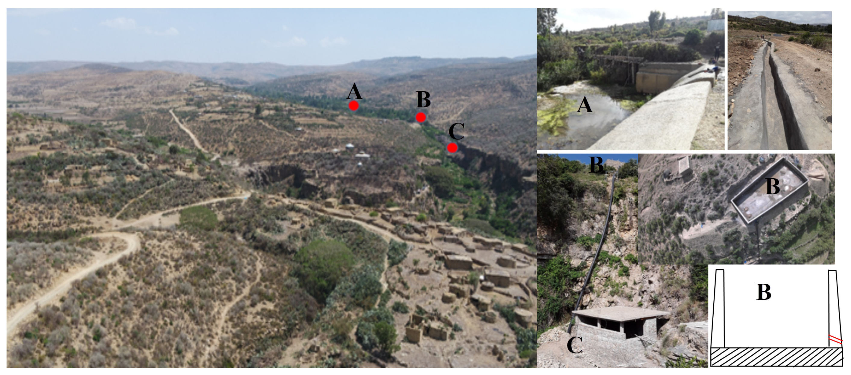
2 of catchment area. The village has a population of about 3000 that is fully dependent on agriculture. Around 450 households were considered to be electrified by the SHP technology in this phase. The power plant is a run-of-river (RoR) type, which depends directly on a natural flowing river and has a higher potential for a cascading project in phase two. Partial views of the village and project site are shown in
Figure 1.
N.B.: The diversion was connected to a small tunnel measuring about 20 m by an open channel. The overall open channel between A and B was about 650 m long, and the penstock that connected B and C was 75 m long.
The available head and stream flow were used to estimate the power plant’s capacity and design. Head measurements were taken at alternative locations using GPS around the entire station. Similarly, flow measurement was conducted using a current meter and the volumetric method during the driest season of the year (the worst-case scenario).
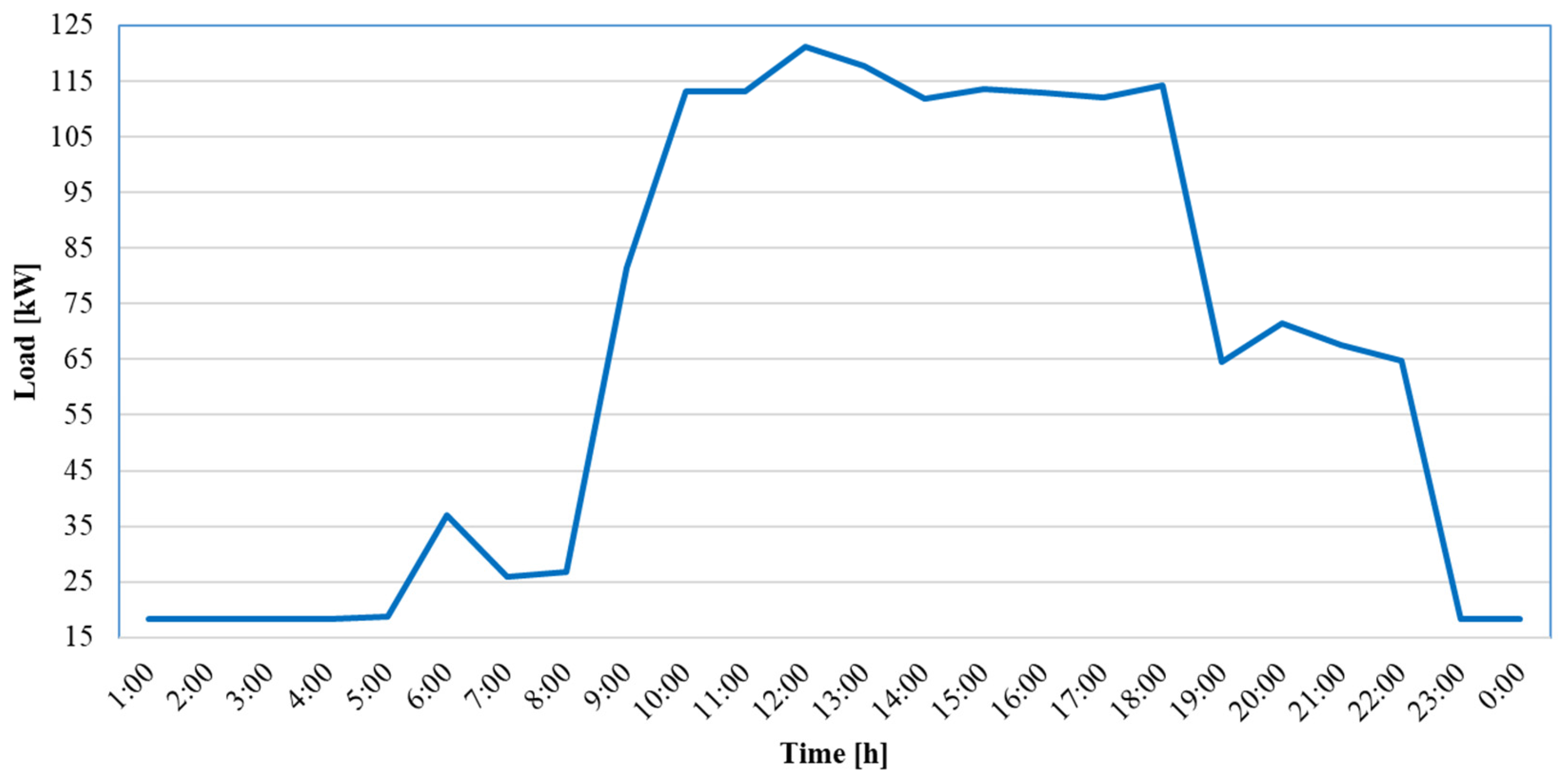
The net head of the power plant was constant and remained 53 m throughout the year, but the power generation depended on user demand and reached a 125 kW peak, as shown in
Figure 2.
Figure 2 was developed based on details from a household economic status survey, the rural electrification target, and a demand growth forecast. This peak power accounts for the demands of small-scale communal industries, community institutions, and household facilities that are forecasted to be established between five and fifteen years after electrification access is created. This curve helped to refine the original design of the turbine and penstock, which underwent size changes from 150 to 125 kW and from twin penstocks to a single penstock, respectively. The volume of the water varies daily and seasonally because of irrigation activity in the upper and lower streams of the powerhouse, but the water was designed to flow constantly at 0.3 m
3/s by providing a small reservoir, as shown in
Figure 1B. The working principle of the RoR design is based on the conversion of the potential (hydraulic) energy of falling water into mechanical energy using a turbine. This turbine is coupled with a generator by a shaft that spins and converts the mechanical energy into electric energy [
4,
5,
6,
7]. Accordingly, the turbine was selected based on the available head, flow rate [
8], construction material, manufacturing capacity, and maintainability [
5,
9,
10,
11].
1.2. Crossflow Turbine
Crossflow turbines are known for their low costs and ease of design and fabrication and have been extensively adopted in low-head installations. Their performance has been studied extensively through numerical and experimental investigations [
9,
11,
12,
13,
14,
15,
16,
17,
18,
19,
20,
21]. A crossflow turbine is made of a nozzle and a runner. The nozzle guides a water jet into the runner, and the runner converts the energy of the water into mechanical rotation. The runner is composed of several blades that are evenly stacked along the periphery with two or more plates. The nozzle guides the water jet to hit the runner blades at an angle called the angle of attack (
). It also has an irregular shape so that a continuous jet of water reaches the runner, transferring the water’s energy with minimal losses and the corresponding maximum efficiency [
15,
20,
22,
23,
24,
25].
2. Methodology
Generally, there are two methods used to design turbines, direct design and inverse design [
12,
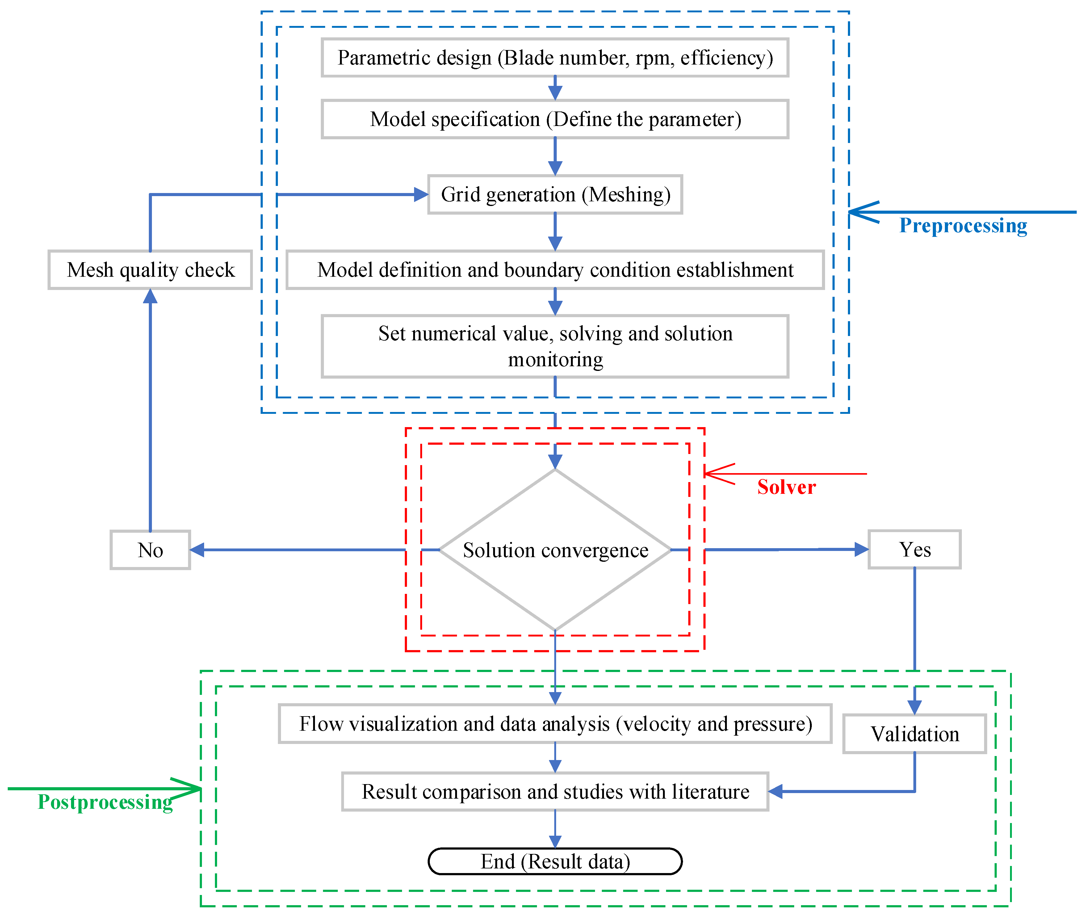
24]. In this work, the direct design method was adopted and ANSYS Computational Fluid Dynamics (CFD) was used to simulate the flow field of the turbine. The direct design method involved two steps: preliminary design, and detailed design and optimization. During preliminary design, the turbine, turbine configuration, and geometric sizing parameters were selected based on site data, including the expected power, head, and flow rate. In the detailed design phase, detailed investigation of the specific flow on the blades and improvement of the design through CFD were performed. In this process, the entire flow mechanism was studied to improve performance by considering the number of blades and the blade profiles. In addition, structural analysis was carried out and simulated to achieve the required strength. This two-step design method was iterated until the optimal result was obtained. A CFD computation flow chart is presented in
Figure 3.
Developing the turbine was challenging, as there was no local experience related to turbine manufacturing in the country. Scaled turbine manufacturing was first conducted using Mekelle University’s workshop facilities and continued at local flexible manufacturing factories that have modern machining and heat treatment facilities. This process provided practical lessons regarding manufacturing challenges, the requirements of manufacturing facilities, quality control, and following standard production procedures. Later, the full-scale turbine manufacturing documented in this manuscript was contracted to Mesfin Industrial Engineering, a local engineering procurement and manufacturing company, with the authors’ supervision and approval of each production step. The turbine was manufactured using numeric control machines, welded by internationally certified welders, and passed the quality control standard of the industry. The technology was simple to transport and was easily assembled and disassembled at the site. A simple manual flow-regulating device was used to adjust the output as per the consumers’ load, so this technology could be used by unskilled operators. Through this process, university–industry linkage in solving practical challenges was demonstrated and the technology was localized.
3. Turbine Design
The Amentila hydropower plant has the operating parameters shown in
Table 1, and they were used as input data to size the crossflow turbine.
3.1. Power Calculation
The theoretical power output was calculated using Equation (1). This was the maximum electric power generated by the turbine.
3.2. Geometrical Sizing of Runner
The runner’s size was expressed in terms of the runner’s length (
L) and diameter (
D) and the jet thickness (
so). The width of the rectangular orifice was always equal to the runner’s length, while the second cross-sectional dimension, jet thickness, was designed for optimal performance. The data used in the design calculations are shown in
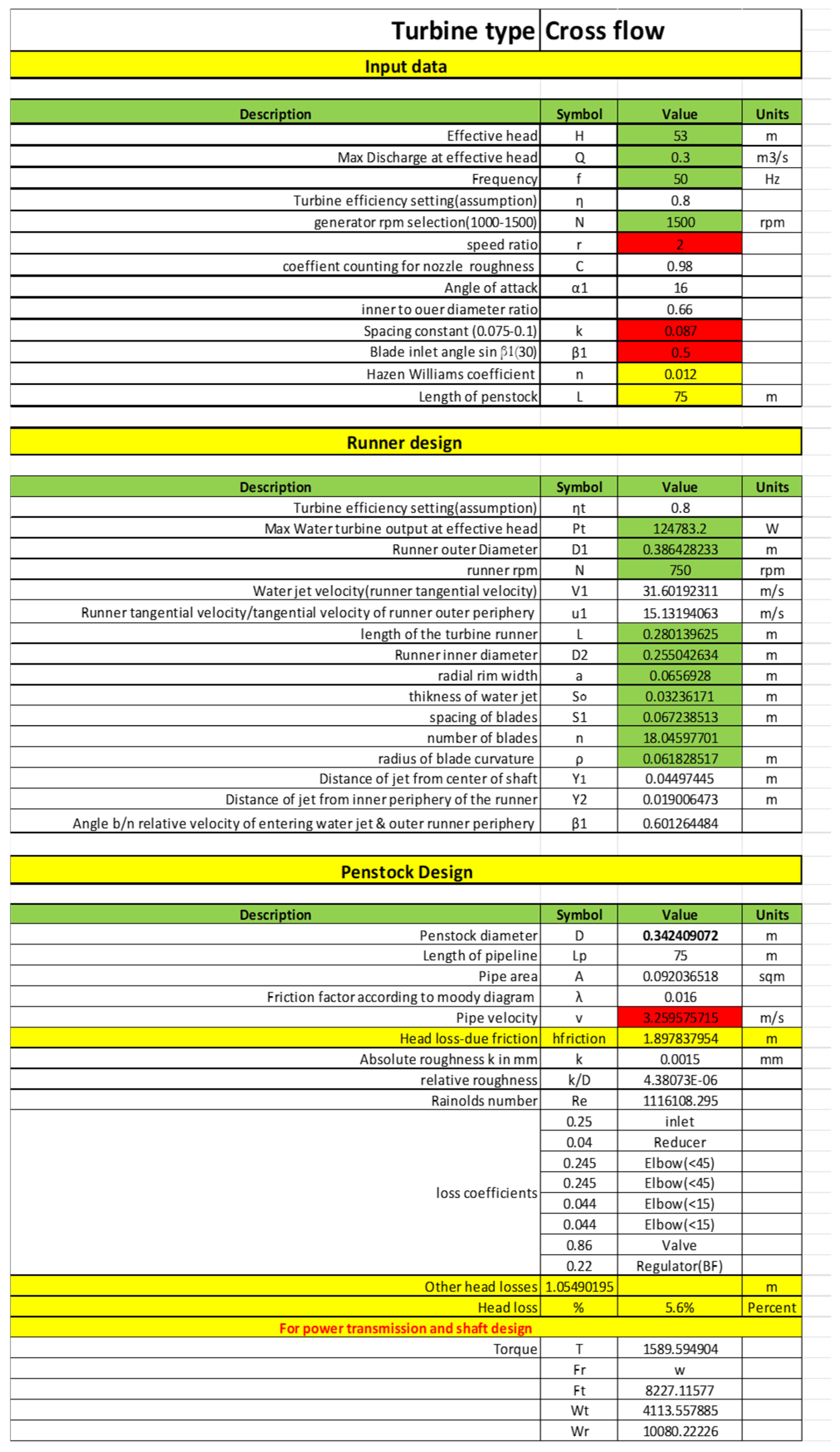
Table 2 and the design procedures is given in
Appendix A. Consequently, the details of the geometrical sizing of the runner are summarized in
Table 3.
3.3. CFD Analysis: Optimal Inlet and Outlet Shapes
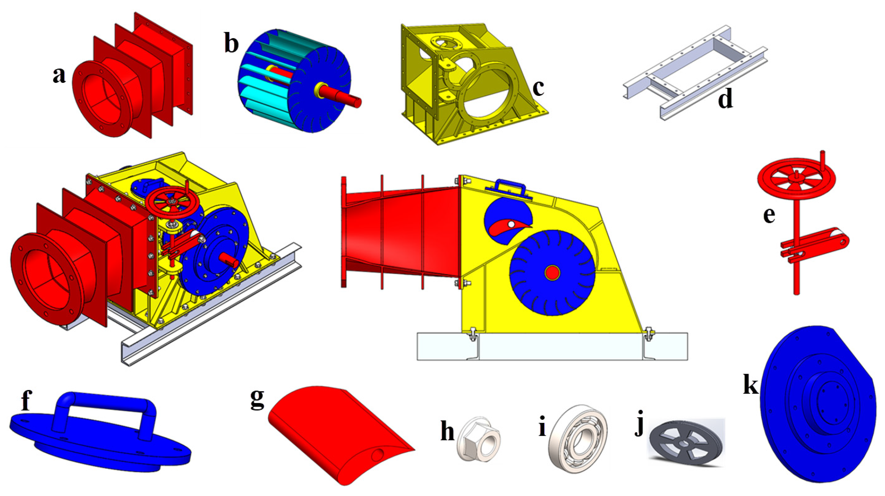
The schematic and CAD model details of the turbine are shown in
Figure 4 and
Figure 5, respectively. These pictures were created using SolidWorks version 2018 based on the parameters presented in
Table 3. Accordingly, the runner was designed with eighteen blades, an outer diameter of 380 mm, and a speed of 750 rpm. The optimal operating and design parameters are given in
Table 1 and
Table 3, respectively. The commercial CFD software ANSYS CFX version 19.2 was used for fluid flow analysis.
3.3.1. Boundary Conditions and Mesh
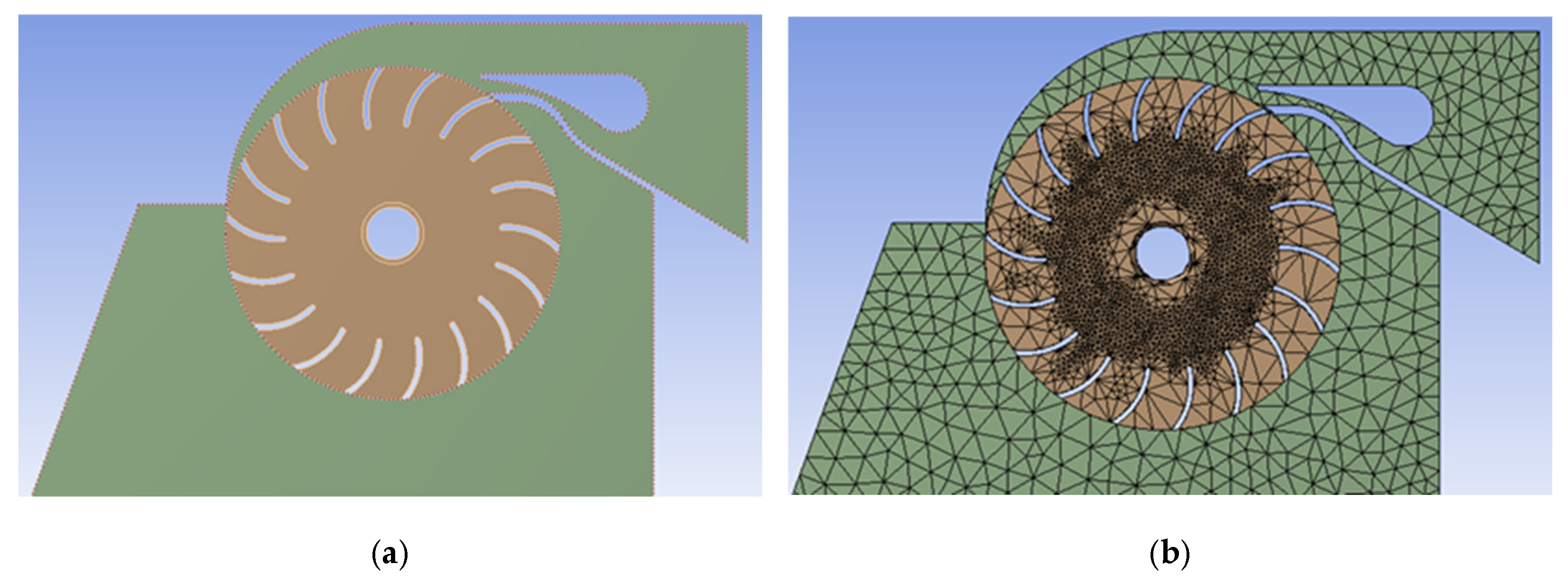
Boundary conditions were defined according to the geometry of the model shown in
Figure 6a. A solid shaft with a diameter of 50 mm was included, so the effect of the angular momentum change in the first stage was considered. The total operating head pressure was specified at the inlet. The inlet was located at the end of the adapter, i.e., between the penstock and the nozzle, and it converted a circular water jet into a rectangular jet, so the flow remained unaffected by any downstream flow irregularities created by the runner’s motion. Uniform pressure was assumed at the inlet. The nozzle was considered with a linear inlet velocity at the ambient temperature. At the exit of the turbine, atmospheric pressure was applied. The turbine rotor was considered a solid moving at 750 rpm, and the outer case was analyzed based on fluid flow over a solid part. The guide vane was also cut off from the fluid part. The walls were specified separately with the respective boundary conditions of no-slip, isothermal, stationary walls.
Considering the complex shape of the turbine, an unstructured mesh (prismatic cells) was used to discretize the model. Generation of the computational mesh domain was defined using SolidWorks. The model schematics and mesh (runner and casing) are shown in
Figure 6.
3.3.2. Grid Independence Verification
Figure 6a shows the unstructured tetrahedral elements used to discretize the computational flow domain. Unstructured meshing helped to capture precise flow dynamics and automatically adjust the mesh when geometric modifications were made. The boundary surfaces, including the blade, shaft, and casing, were treated using a first-layer inflation technique. Additional layers were added with a 5% growth rate to enhance the resolution of near-wall flow behavior. The wall boundary layer simulation accuracy was assessed using a dimensionless parameter (
Y+). This parameter gave an estimation of the distance between the wall and the first grid cell, i.e., the thickness of the viscous sublayer. The value of this parameter gave a better representation of the flow separation and the pressure gradient near the walls. The flow profile was validated through mesh refinement analysis. This analysis ensured the simulation results were independent of the discretization parameters. In addition, sensitivity analysis was carried out by selecting torque as a monitoring variable. Accordingly, the result gave an average element size of 3 mm, corresponding to 790,000 mesh elements, and stabilized after 670 iterations.
3.3.3. Momentum and Turbulence (k-ε) Equation
The total pressure was computed based on the dynamic pressure and static pressure of the water flow through the turbine, including the nozzle. Since water is incompressible, the density and temperature of water do not affect the magnitude of pressure. Accordingly, the pressure variation was due to the hydraulic head and the flow of water through different configurations. The dynamic pressure depended on the flow’s velocity. This circumstance was easily observed in illustrations of total pressure contours. The static pressure of the flow was computed based on the static head of the flow through the penstock via the nozzle. Since fluid flow properties like density do not change with application of pressure, it was affected by the hydraulic head. In general, the flow was assumed to be isothermal. Temperature variation did not affect the pressure of the water inside the penstock and turbine blades. This analysis helped to check the qualitative and quantitative design results. For practical purposes, emphasis was given to the velocity, flow angle, and pressure, which were found to be significant for turbine performance.
4. Results and Discussion
4.1. Computational Results and Design Parameters
A standard procedure to validate CFD results is to compare the parameters of interest with experimental results. However, no experimental study was carried out. Nevertheless, errors and uncertainties were minimized by iteration convergence and grid independence studies. While iteration convergence helped to ensure converged solutions, grid independence helped to narrow discretization errors. The model was then tested with experimental results from smaller turbines. Afterwards, the model was used to obtain the optimal geometrical shape of the turbine for defined performance flow fields.
The key objective to improve turbine performance was to increase the change in angular momentum at the runner’s boundary surface. This was achieved by maximizing the angular momentum of the flow at the inlet and minimizing it at the outlet. From a design point of view, matching the nozzle and impeller geometries was important. By analyzing the flow field around the impeller, it was determined that if the relative angular velocity decreases across a blade row, then work is extracted from the flow, and work is added to the flow when the reverse happens.
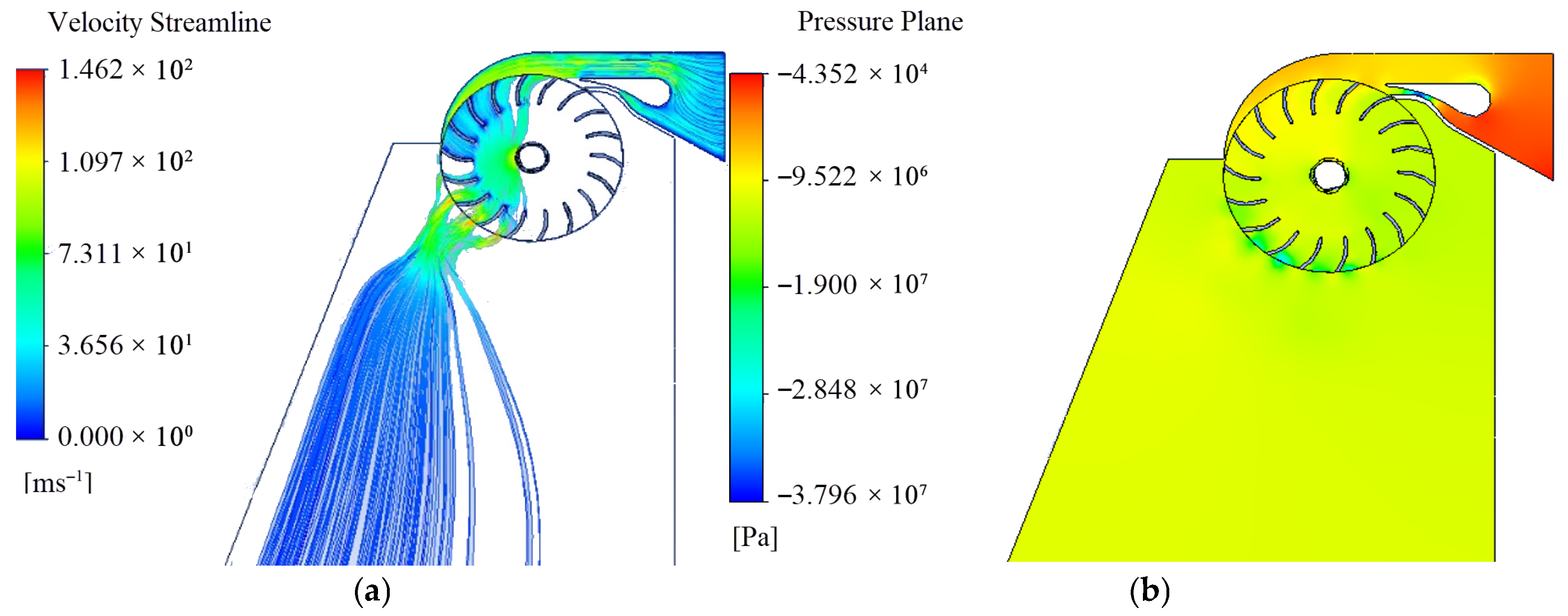
Figure 7 shows simulation results for the flow field around the impeller and nozzle. This enabled the pressure, velocity, and flow angles around the impeller to be computed. As can be observed in the velocity profile, the flow at the runner inlet was predominantly in a tangential direction, indicating that the angular momentum flux was expected to increase. However, the flow at the exit of the impeller was in a radial direction, which indicated reduced angular momentum.
4.2. Static Structural Analysis of the Runner Blade
Static structural analysis evaluates stress, deformation, and safety factors of structures subjected to steady static or dynamic loads. This type of analysis is usually used to determine if a structure can safely withstand a specified load by studying the applied stress and yield/ultimate stress of the material used. The von Mises stress criterion is used to predict the yielding of ductile materials. The ratio of yield stress to applied stress is called the safety factor (FS). While an SF < 1 indicates failure risks, an SF > 1 indicates a structure can withstand the applied load and stress. In this paper, a worst-case scenario that was constrained at both ends and a real scenario with a remote displacement constraint were considered to analyze the structural deformation of the runner. The runner was made of structural steel
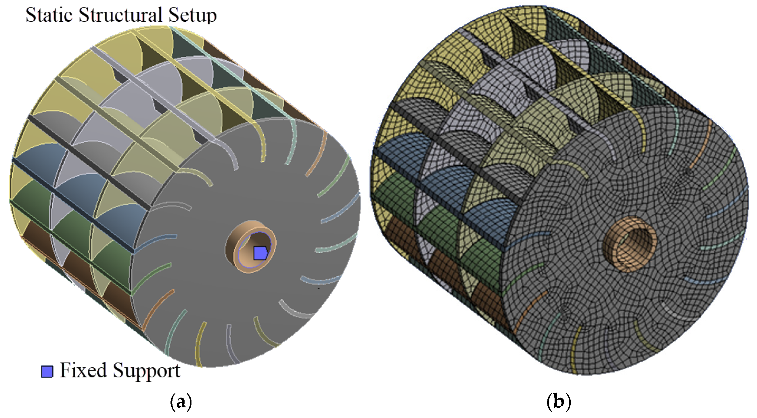
37 with a yield strength of 235 MPa. The CFD results with maximum deformation and pressure on the blades are presented here for the simulation setup shown in
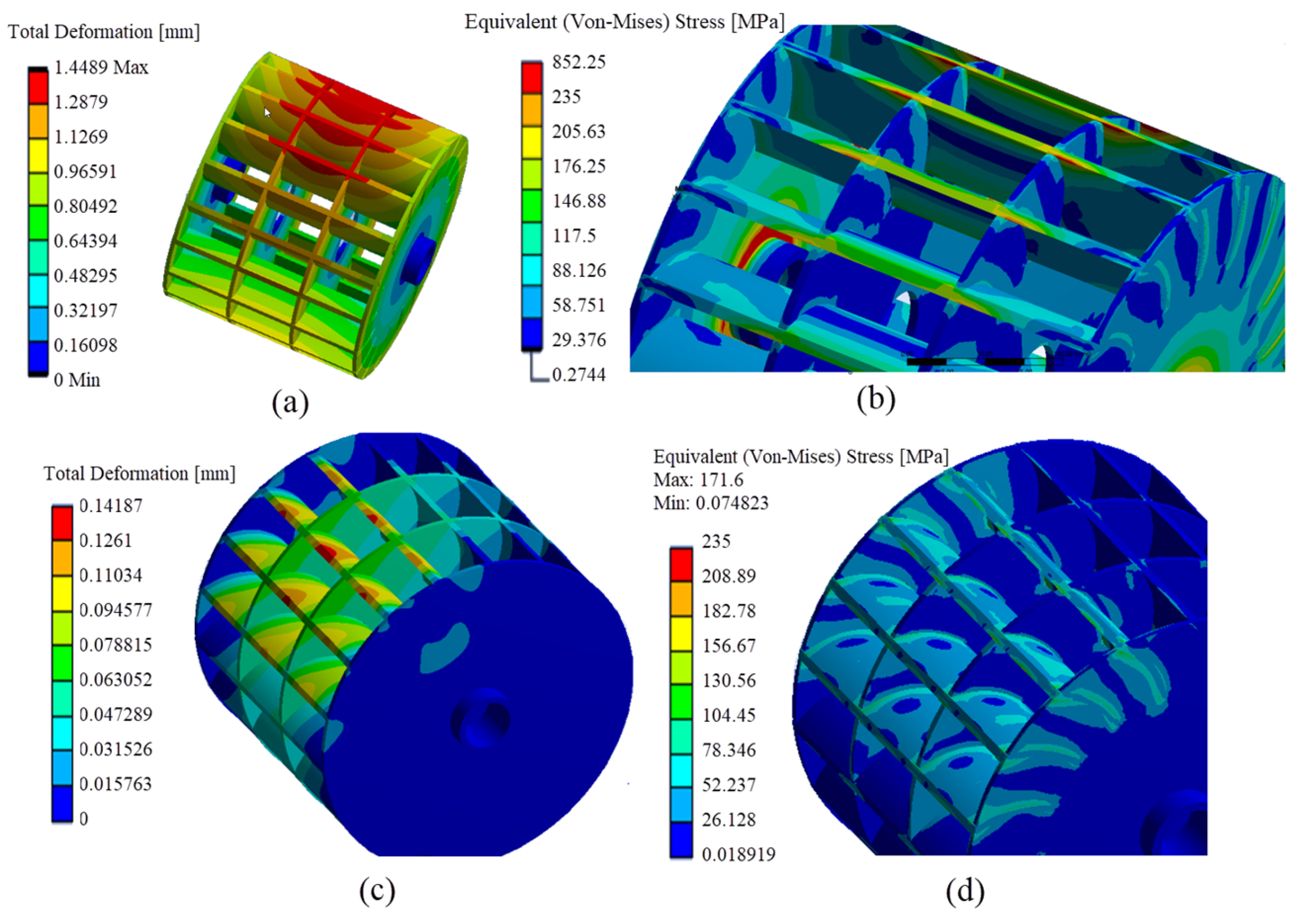
Figure 8. The maximum deformations of the blades at the center were found to be 1.45 mm and 0.14 mm for the first and second scenarios, respectively, as shown in
Figure 9a,c. Similarly, the von Mises stress values were found to be 271 MPa and 148 MPa in the first and second scenarios, respectively, as shown in
Figure 9b,d. While the first scenario indicated a risk condition with a safety factor of 0.87, the second scenario gave a safe condition with a safety factor of 1.59.
4.3. Modal Analysis of the Runner Blade
Modal analysis is a computational process for predicting modal parameters such as the resonant frequency, mode shape, and damping. It was used during the initial design and design evolution stages that enabled the authors to numerically analyze the turbine model before fabrication. Accordingly, it determined the natural mode shapes and frequencies of the runner during free vibration. Since the designed turbine operates at 750 rpm, its corresponding working frequency was found to be 12.5 Hz using Equation (16).
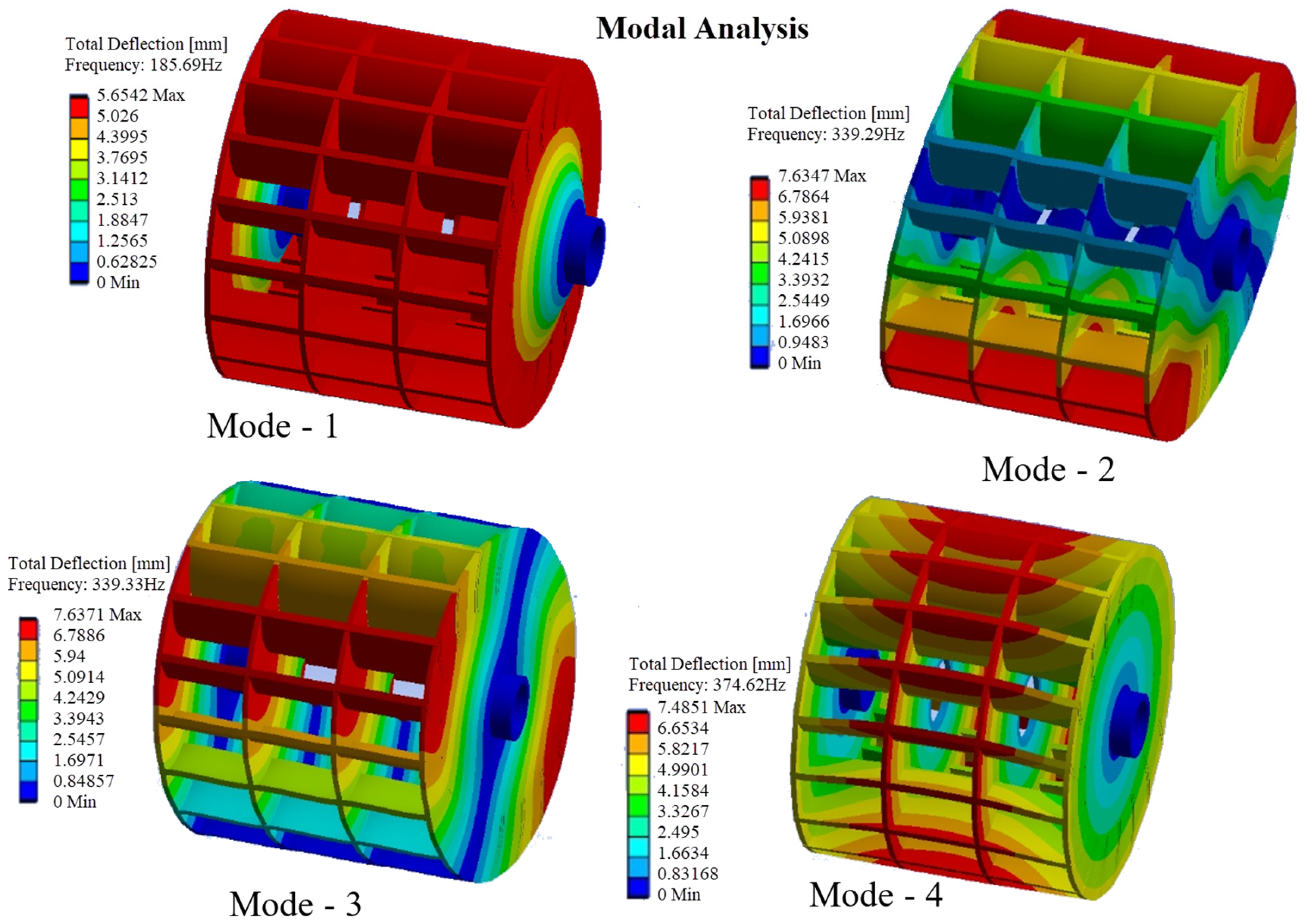
Based on this analysis, four first mode shapes named mode 1 to mode 4 with frequencies of 186, 339, 339, and 375 Hz, respectively, were obtained, as shown in
Figure 10. Based on this analysis, the working frequency and the natural frequencies of the runner in the four mode shapes were far from each other, indicating the turbine structure has no tendency to resonate.
5. Construction
Fabrication of the turbine was performed at Mesfin Industrial Engineering (MIE). This company has no history of developing any kind of turbine but has rich experience in developing hydropower components (steel penstocks, gates, cranes, and other steel structures) for hydropower plants.
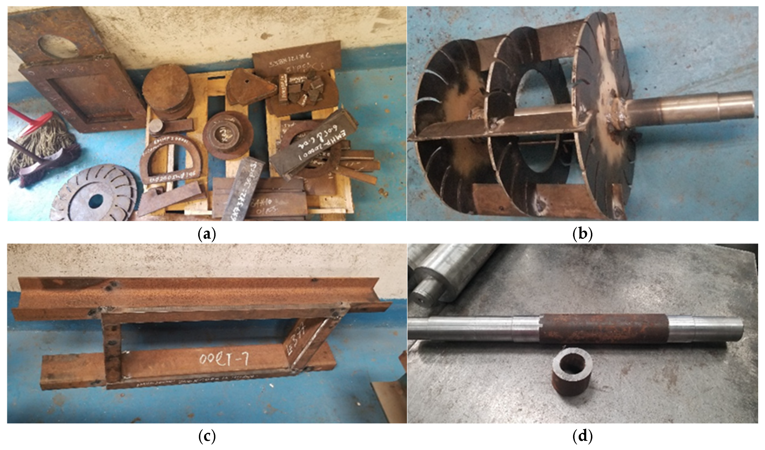
The general principle followed here was to avoid complex fabrication techniques like casting, to use locally available materials, and to make assembly and disassembly as simple as possible. Crossflow turbine fabrication involved fabrication of the main parts, such as the support frame, the turbine casing, the runner, a nozzle with an adjustable guide vane, and different-sized bearing holders. The runner was made of three circular discs, a shaft, and eighteen blades, as shown in
Figure 11. The three circular discs were grooved into eighteen parts, using a pantograph to hold the blades. Later, they welded on bushes that fit forcefully onto the shaft, as shown in
Figure 11b. The shaft was machined in a numeric controlled lathe machine with the required dimensions, surface finish, and tolerance. The support frame was made of standard C-channels welded together, as shown in
Figure 11c. The blades were fitted into the grooves of the discs and welded. The assembled runner was then machined to obtain the correct dimensions and mass balance. Two bearings were fitted on the assembled runner before it was fitted in the bearing holders.
Different-sized bearing holders were made for the runner and guide vane assembly, as shown in
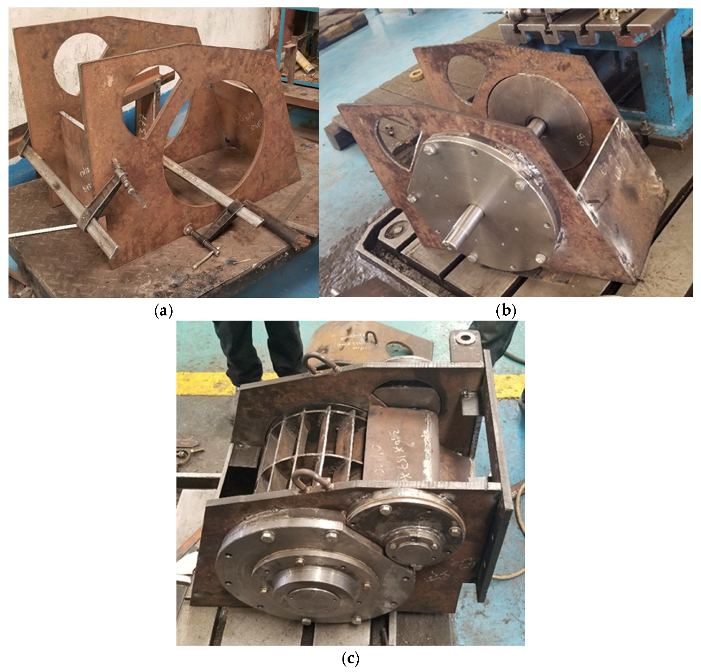
Figure 12a. These components were first cut in a pantograph with rough dimensions, then refined in a lathe machine for accurate dimensions and tolerances. Different-sized holes were then drilled around these holders to attach them to the casing. Holders with large thicknesses were made by welding two discs. The turbine casing in
Figure 13a was made by cutting two side plates, then welding them with support frames. The side plates were first cut by a pantograph, then all the mating parts of these plates were machined for accurate fitting. Later, holes were drilled for standard bolt assembly.
With all parts in place, final welding with high strength and no leakage was performed on the casing, as shown in
Figure 13c. All bearing holders were then fastened to the casing using bolts. All components were made of steel 37 (St-37), which was imported and easily available in the local market. All bolts, bearings, and flanges used were imported and selected as per the standard.
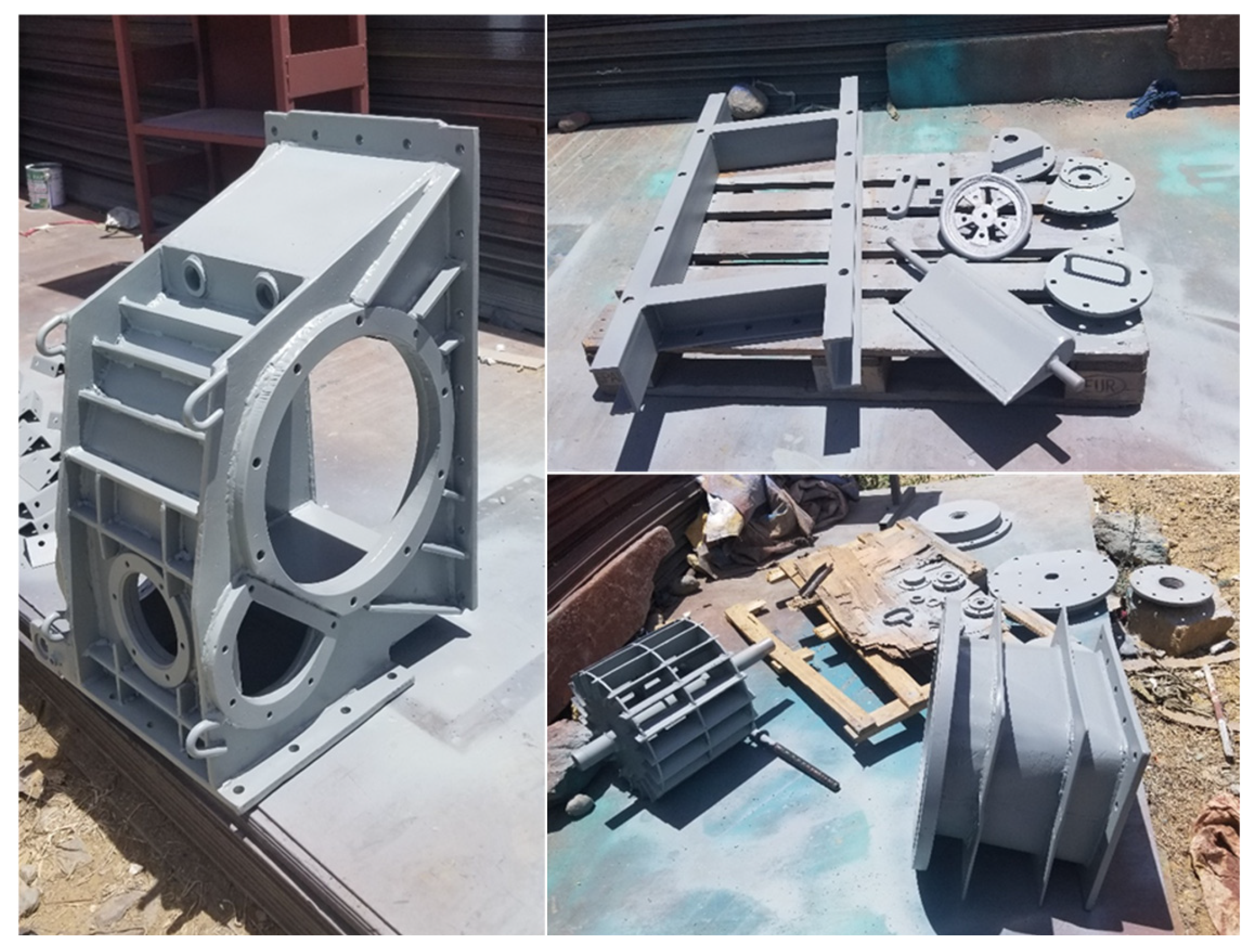
After quality inspection and testing, all components were painted with three layers of paint, as shown in
Figure 14 and
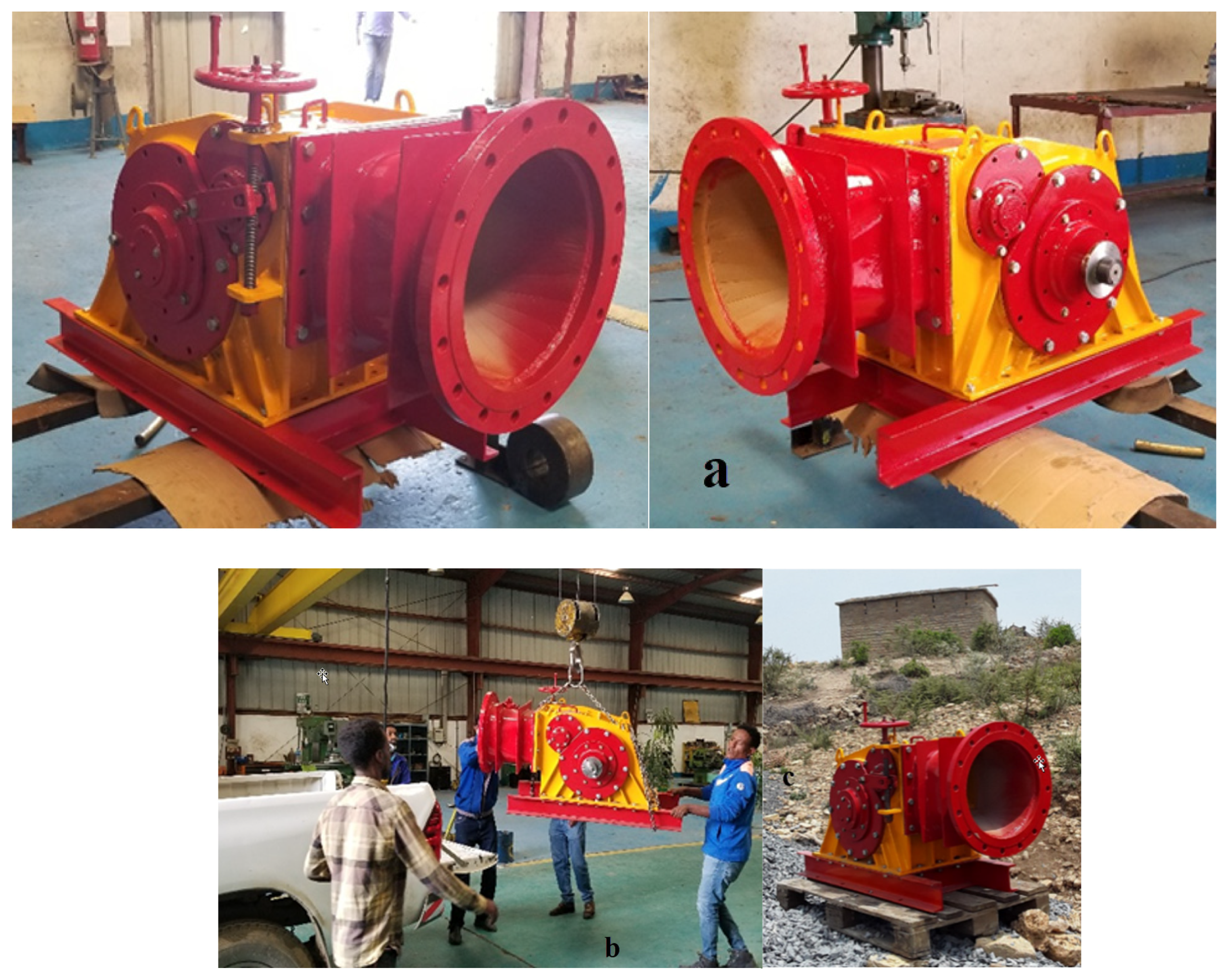
Figure 15. The total mass of the assembled turbine in
Figure 15 was 6 tons.
6. Conclusions
This research detailed the design, computational analysis, and development of a crossflow turbine. This turbine was engineered based on local hydrological conditions (0.3 m3/s of discharge and 53 m head) to meet the electricity demand of about 450 households. The turbine has an 18-blade runner with a 16° blade profile, and it was computationally verified to achieve a peak output of 125 kW at 80% efficiency. In addition, the computational results indicated critical performance characteristics, including a constant angle of attack, maximized angular momentum transfer at the runner inlet, and smooth laminar flow in the first and second stages of the turbine. Later the turbine was manufactured, meeting all test standards. Currently, it is ready to be commissioned at the Amentila SHP plant, a standalone off-grid system developed to provide a rural electrification solution. The methodological and technical lessons presented in this paper are important for advancing sustainable off-grid energy solutions in the south. This study serves as a proof of concept for demand-driven off-grid electrification, and it provides essential practical insights for SHP developers and policymakers, highlighting the necessity of designing research strategies based on government policies and changing stakeholders’ attitudes to support building local capacity and technology adoption.
Recommendations
Though hydropower turbines have not been designed or developed in Ethiopia and engineering manufacturers are not considering the design and development of turbines as their core business, the authors believe this paper provides unique practical experience that can be considered eye-opening for off-grid electrification stakeholders such as research universities, communities, manufacturing industries, and the power sector (Utility). Accordingly, the authors recommend the following points as a way forward:
Hoping existing war crises will improve in the project region, the authors recommend commissioning and performance testing the technology.
Locally manufacturing the crossflow turbine was found to be easy and manageable. The authors observed the SHP project’s economic impact on the community, as it promoted irrigation, and the site became a demonstration site where off-grid electrification lessons were given to many rural electrification and rural development stakeholders. The authors encourage these actors to rethink and modify their off-grid electrification and rural development strategies towards effective approaches based on the water–energy–food–environment nexus.
The authors encourage Mekelle University and its stakeholders to push forward and use this intervention as a benchmark to mobilize local communities to cooperate and own such technological solutions through community-owned business models.
Author Contributions
A.H.T. contributed to the conceptualization, method, analysis, interpretation, supervision, drafting and redrafting of the manuscript, and editing. S.A.W. contributed to the method, analysis, interpretation, and drafting of the manuscript. K.G.G. contributed to the method, analysis, and drafting of the manuscript. All authors have read and agreed to the published version of the manuscript.
Funding
This research received no external funding.
Data Availability Statement
Necessary data are contained within this article. However, if further data are required, they will be available on request.
Acknowledgments
The authors want to acknowledge Mekelle University for committing to finance the development of a small hydropower plant to demonstrate water–energy–food–environment nexus research. In addition, the authors wish to express special gratitude to Nigus Abebe, who worked as a civil engineering team leader; Melkamu Nibret, who worked as an electrical team leader; and Henok Mezgebe, who voluntarily supported the mechanical team by providing a licensed computational facility during the design stage. Finally, the authors want to acknowledge Endu Atsbeha for his transportation service in all stages of this work and Zekarias, chief engineer from the manufacturer, for his professionalism and his extraordinary commitment to visit the project site before installation.
Conflicts of Interest
The authors declare no conflicts of interest.
Nomenclature
| Symbol/Abbreviation | Description |
| CFD | Computational Fluid Dynamics |
| D | Diameter |
| D1 | Runner’s outer diameter |
| D2 | Runner’s inner diameter |
| H | Total head |
| L | Runner’s length |
| Number of blades |
| P | Output power |
| Q | Flow rate |
| RoR | Run-of-river |
| Throat width/jet thickness |
| t | Blade thickness |
| Angle of attack |
| Outer blade’s inlet angle |
| Blade’s exit angle |
| Radius of blade curvature |
| θ | Profile arc |
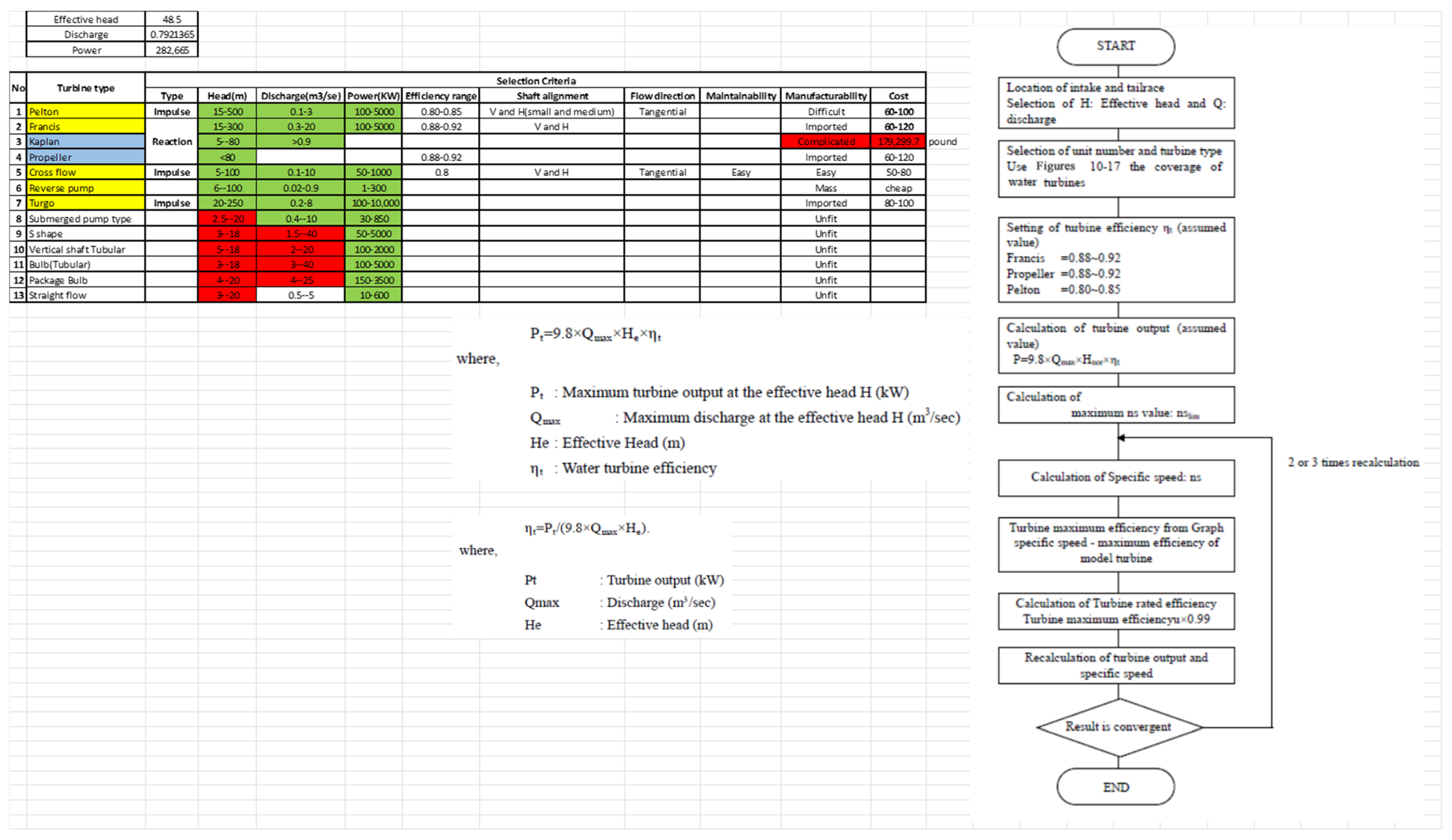
Appendix A
Figure A1.
Turbine selection procedure chart.
Figure A1.
Turbine selection procedure chart.
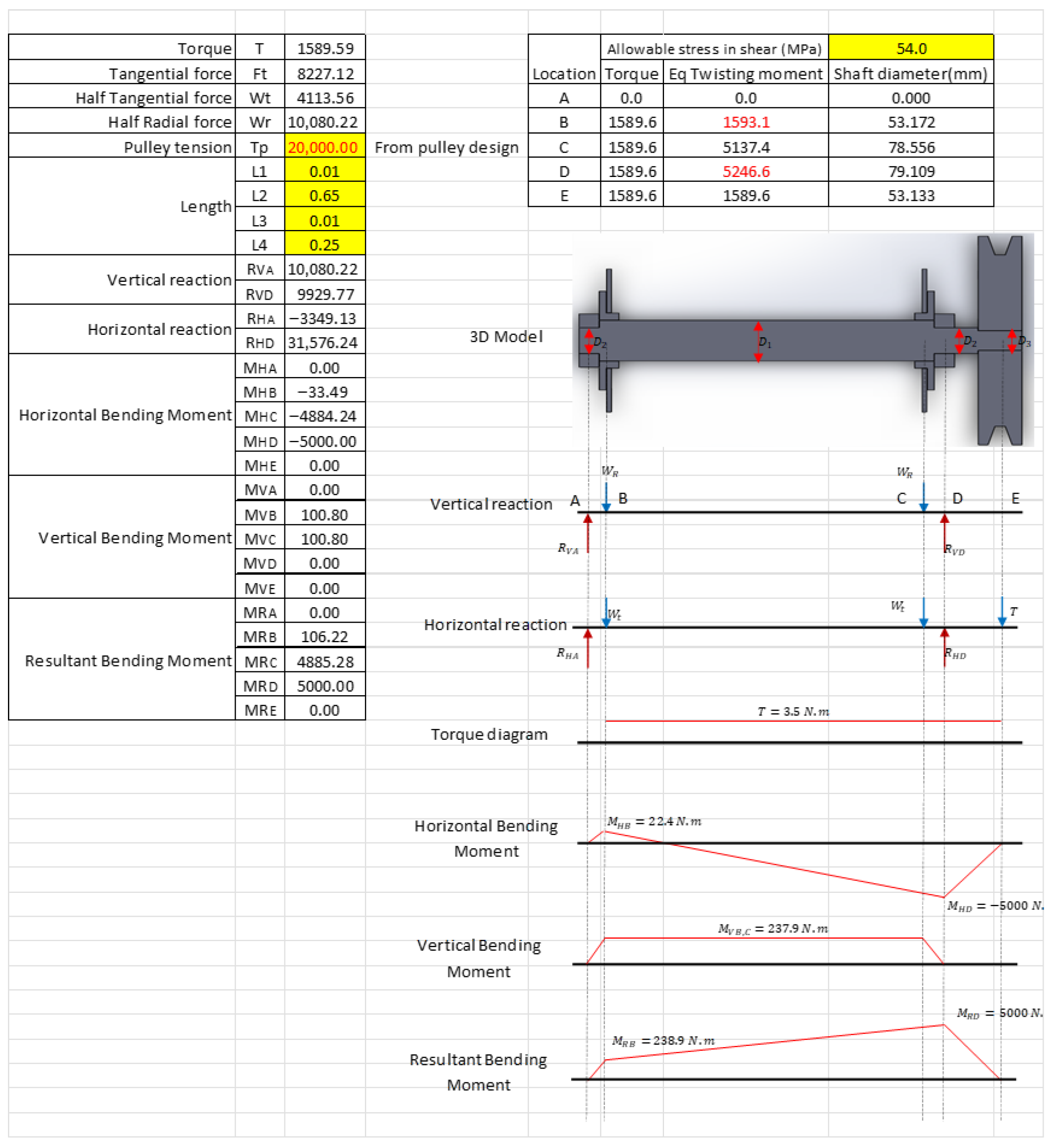
Figure A2.
Crossflow turbine design procedure.
Figure A2.
Crossflow turbine design procedure.
References
- Wu, G.C.; Deshmukh, R.; Ndhlukula, K.; Radojicic, T.; Reilly, J. Renewable Energy Zones for the Africa Clean Energy Corridor; Technical Report Number: LBNL-187271; Lawrence Berkeley National Laboratory: Berkeley, CA, USA, 2015. [Google Scholar] [CrossRef]
- Dalelo, A. Rural Electrification in Ethiopia: Opportunities and Bottlenecks. Ph.D. Thesis, Addis Ababa University, Addis Ababa, Ethiopia, 2003. Available online: https://www.academia.edu/115469209/Rural_Electrification_in_Ethiopia_Opportunities_and_Bottlenecks (accessed on 29 June 2025).
- Cheever, M.; Graichen, K.; Homeier, D.; Howell, J.; Kefauver, O.; Kimball, T. Environmental Policy Review: Key Issues in Ethiopia 2011. In Chapter 6 Rural Electrification & Renewable Energy in Ethiopia; Colby College Environmental Policy Group: Waterville, Maine, 2011; pp. 1–29. Available online: https://web.colby.edu/eastafricaupdate/ (accessed on 29 June 2025).
- Elbatran, A.; Yaakob, O.; Ahmed, Y.M.; Shabara, H. Operation, performance and economic analysis of low head micro-hydropower turbines for rural and remote areas: A review. Renew. Sustain. Energy Rev. 2015, 43, 40–50. [Google Scholar] [CrossRef]
- Razak, J.A.; Ali, Y.; Alghoul, M.; Zainol, M.S.; Zaharim, A.; Sopian, K. Application of Crossflow Turbine in Off-Grid Pico Hydro Renewable Energy System. Proceeding Am.-Math 2010, 10, 519–526. [Google Scholar]
- Du, J.; Yang, H.; Shen, Z.; Guo, X. Development of an inline vertical cross-flow turbine for hydropower harvesting in urban water supply pipes. Renew. Energy 2018, 127, 386–397. [Google Scholar] [CrossRef]
- Achebe, C.H.; Okafor, O.C.; Obika, E.N. Design and implementation of a cross fl ow turbine for Pico hydropower electricity generation. Heliyon 2020, 6, 04523. [Google Scholar] [CrossRef] [PubMed]
- McLean, E.; Kearney, D. An Evaluation of Seawater Pumped Hydro Storage for Regulating the Export of Renewable Energy to the National Grid. Energy Procedia 2014, 46, 152–160. [Google Scholar] [CrossRef]
- Vortex, F.; Sritram, P.; Suntivarakorn, R. The Efficiency Comparison of Hydro Turbines for Micro Power. Energies 2021, 14, 7961. [Google Scholar] [CrossRef]
- Adhikari, R.; Wood, D. Computational Analysis of a Double-Nozzle Crossflow Hydroturbine. Energies 2018, 11, 3380. [Google Scholar] [CrossRef]
- Dragomirescu, A.; Schiaua, M. Experimental and Numerical Investigation of a Bánki Turbine Operating far away from Design Point. Energy Procedia 2017, 112, 43–50. [Google Scholar] [CrossRef]
- Adhikari, R. Design Improvement of Crossflow Hydro Turbine. Ph.D. Thesis, University of Calgary, Calgary, AB, Canada, 2016. [Google Scholar] [CrossRef]
- Adhikari, R.; Wood, D. The Design of High Efficiency Crossflow Hydro Turbines: A Review and Extension. Energies 2018, 11, 267. [Google Scholar] [CrossRef]
- Sinagra, M.; Tucciarelli, T.; Picone, C.; Aricò, C.; Hannachi, M. Design of Reliable and Efficient Banki-Type, Environ. Sci. Proc. 2020, 2, 49. [Google Scholar] [CrossRef]
- De Andrade, J.; Curiel, C.; Kenyery, F.; Aguillón, O.; Vásquez, A.; Asuaje, M. Numerical Investigation of the Internal Flow in a Banki Turbine. Int. J. Rotating Mach. 2011, 4, 14. [Google Scholar] [CrossRef]
- Mehr, G.; Durali, M.; Khakrand, M.H.; Hoghooghi, H. A novel design and performance optimization methodology for hydraulic Cross-Flow turbines using successive numerical simulations. Renew. Energy 2021, 169, 1402–1421. [Google Scholar] [CrossRef]
- Sinagra, M.; Picone, C.; Aricò, C.; Pantano, A.; Tucciarelli, T.; Hannachi, M.; Driss, Z. Impeller Optimization in Crossflow Hydraulic Turbines. Water 2021, 13, 313. [Google Scholar] [CrossRef]
- Totapally, H.G.; Aziz, N.M. Refinement of Cross-Flow Turbine Design Parameters. J. Energy Eng. 1994, 120, 133–147. [Google Scholar] [CrossRef]
- Budiarso, W.; Adanta, D.; Iaeng, M. Computational analysis of flow field on cross-flow hydro turbines. Eng. Lett. 2021, 29, 87–94. [Google Scholar]
- Sammartano, V.; Aricò, C.; Carravetta, A.; Fecarotta, O.; Tucciarelli, T. Banki-Michell Optimal Design by Computational Fluid Dynamics Testing and Hydrodynamic Analysis. Energies 2013, 6, 2362–2385. [Google Scholar] [CrossRef]
- Sammartano, V.; Morreale, G.; Sinagra, M.; Tucciarelli, T. Numerical and experimental investigation of a cross-flow water turbine. J. Hydraul. Res. 2016, 54, 321–331. [Google Scholar] [CrossRef]
- Choi, Y.D.; Lim, J.I.; Kim, Y.T.; Lee, Y.H. Performance and Internal Flow Characteristics of a Cross-Flow Hydro Turbine by the Shapes of Nozzle and Runner blade. J. Fluid Sci. Technol. 2008, 3, 398–409. [Google Scholar] [CrossRef]
- Mrope, H.A.; Abeid, Y.; Jande, C.; Kivevele, T.T. A Review on Computational Fluid Dynamics Applications in the Design and Optimization of Crossflow Hydro Turbines. J. Renew. Energy 2021, 2021, 7048. [Google Scholar] [CrossRef]
- Adhikari, R.; Wood, D. A new nozzle design methodology for high efficiency crossflow hydro turbines. Energy Sustain. Dev. 2017, 41, 139–148. [Google Scholar] [CrossRef]
- Warjito, W.; Budiarso, B.; Celine, K.; Nasution, S.B.S. Computational Method for Designing a Nozzle Shape to Improve the Performance of Pico-Hydro Crossflow Turbines. Int. J. Technol. 2021, 12, 139–148. [Google Scholar] [CrossRef]
- Chen, Z.M.; Choi, Y.D. Performance and internal flow characteristics of a cross-flow turbine by guide vane angle. IOP Conf. Ser. Mater. Sci. Eng. 2013, 52, 052031. [Google Scholar] [CrossRef]
- Du, J.; Shen, Z.; Yang, H. Effects of different block designs on the performance of inline cross-fl ow turbines in urban water mains. Appl. Energy 2018, 228, 97–107. [Google Scholar] [CrossRef]
- Adanta, D.; Warjito, B.; Prakoso, A.P.; Wijaya, E.P. Effect of Blade Depth on the Energy Conversion Process in Crossflow Turbines. CFD Lett. 2020, 12, 123–131. [Google Scholar]
- Bachant, P.; Wosnik, M. Effects of Reynolds Number on the Energy Conversion and Near-Wake Dynamics of a High Solidity Vertical-Axis Cross-Flow Turbine. Energies 2016, 9, 73. [Google Scholar] [CrossRef]
- Assefa, E.Y.; Tesfay, A.H. Effect of Blade Number on Internal Flow and Performance Characteristics in Low-Head Cross-Flow Turbines. Energies 2025, 18, 318. [Google Scholar] [CrossRef]
Figure 1.
Amentila small hydro site: (A) diversion, (B) reservoir, and (C) powerhouse.
Figure 1.
Amentila small hydro site: (A) diversion, (B) reservoir, and (C) powerhouse.
Figure 2.
Daily load duration curve of Amentila Village.
Figure 2.
Daily load duration curve of Amentila Village.
Figure 3.
Flow chart of CFD workflow using ANSYS CFX.
Figure 3.
Flow chart of CFD workflow using ANSYS CFX.
Figure 4.
Schematics of turbine nozzle arc, impeller, and blade geometry.
Figure 4.
Schematics of turbine nozzle arc, impeller, and blade geometry.
Figure 5.
CAD model of turbine components and 3D assembling: (a) adapter, (b) runner, (c) casing, (d) skid support, (e) power screw, (f) top cover, (g) guide vane, (h) nut, (i) bearing, (j) wheel, and (k) side cover.
Figure 5.
CAD model of turbine components and 3D assembling: (a) adapter, (b) runner, (c) casing, (d) skid support, (e) power screw, (f) top cover, (g) guide vane, (h) nut, (i) bearing, (j) wheel, and (k) side cover.
Figure 6.
Structural ANSYS analysis schematics of runner: (a) model discretization and (b) meshing.
Figure 6.
Structural ANSYS analysis schematics of runner: (a) model discretization and (b) meshing.
Figure 7.
Optimal CFD results: (a) velocity profile and (b) pressure profile.
Figure 7.
Optimal CFD results: (a) velocity profile and (b) pressure profile.
Figure 8.
ANSYS setup: (a) fixed support setup and (b) meshing.
Figure 8.
ANSYS setup: (a) fixed support setup and (b) meshing.
Figure 9.
Structural stress behavior: (a,c) deformation and (b,d) von Mises stress.
Figure 9.
Structural stress behavior: (a,c) deformation and (b,d) von Mises stress.
Figure 10.
The mode shapes of the runner.
Figure 10.
The mode shapes of the runner.
Figure 11.
Runner fabrication process: (a) component inventory, (b) partially assembled runner, (c) skid support, and (d) shaft and bush.
Figure 11.
Runner fabrication process: (a) component inventory, (b) partially assembled runner, (c) skid support, and (d) shaft and bush.
Figure 12.
Components of turbine support: (a) side cover, flange ring, bearing, and shaft and (b) adapter.
Figure 12.
Components of turbine support: (a) side cover, flange ring, bearing, and shaft and (b) adapter.
Figure 13.
Fabrication and assembly process: (a) casing arranged for welding, (b) shaft and side cover assembly trial, and (c) full assembly for inspection.
Figure 13.
Fabrication and assembly process: (a) casing arranged for welding, (b) shaft and side cover assembly trial, and (c) full assembly for inspection.
Figure 14.
Painting and drying components.
Figure 14.
Painting and drying components.
Figure 15.
Finishing, receiving, and transportation: (a) prepared turbine at manufacturing company, (b) transportation to site, and (c) prepared turbine at installation site.
Figure 15.
Finishing, receiving, and transportation: (a) prepared turbine at manufacturing company, (b) transportation to site, and (c) prepared turbine at installation site.
Table 1.
Input data.
| Parameter | Unit | Symbol | Value |
|---|
| Effective head | m | | 53 |
| Max discharge at effective head | m3/s | | 0.3 |
| Frequency | Hz | | 50 |
| Generator speed selection (1000–1500) | rpm | | 1500 |
| Length of penstock | m | | 75 |
| Acceleration due to gravity | m/s2 | g | 9.81 |
| Water density at 4 °C | kg/m3 | ρ | 1000 |
Table 2.
Design data.
| Parameter Description | Parameter | Value |
|---|
| Turbine and generator efficiency | | 0.8 |
| Speed ratio | | 2 |
| Coefficient accounting for nozzle roughness | | 0.98 |
| Angle of attack | | 16° |
| Inner diameter to outer diameter ratio | | 0.66 |
| Spacing constant | | 0.087 |
| Blade’s outer angle | | 30° |
| Hazen–Williams coefficient | | 0.012 |
Table 3.
The geometrical size of the runner.
Table 3.
The geometrical size of the runner.
| No. | Description of Parameter | Parameter | Unit | Equation | Eq. | Value |
|---|
| 1 | Max turbine output | | kW | | | 125 |
| 2 | Runner’s outer diameter | | m | | | 0.38 |
| 3 | Runner’s rpm | | rpm | | | 750 |
| 4 | Water jet velocity | | m/s | | | 31.6 |
| 5 | Runner’s tangential velocity | | m/s | | | 15.13 |
| 6 | Runner’s length | | m | | | 0.28 |
| 7 | Runner’s inner diameter | | m | | | 0.25 |
| 8 | Radial rim width | | m | | | 0.065 |
| 9 | Thickness of water jet | | m | | | 0.032 |
| 10 | Spacing of blades | | m | | | 0.067 |
| 11 | Number of blades | | --- | | | 18.05 |
| 12 | Radius of blade curvature | | m | | | 0.061 |
| 13 | Distance of jet from center of shaft | | m | | | 0.044 |
| 14 | Distance of jet from inner periphery of runner | | m | | | 0.019 |
| 15 | Inner blade angle | | ° | | | 90 |
| Disclaimer/Publisher’s Note: The statements, opinions and data contained in all publications are solely those of the individual author(s) and contributor(s) and not of MDPI and/or the editor(s). MDPI and/or the editor(s) disclaim responsibility for any injury to people or property resulting from any ideas, methods, instructions or products referred to in the content. |
© 2025 by the authors. Licensee MDPI, Basel, Switzerland. This article is an open access article distributed under the terms and conditions of the Creative Commons Attribution (CC BY) license (https://creativecommons.org/licenses/by/4.0/).
