1. Introduction
The growing implementation of Brushless DC (BLDC) motors in electric vehicles (EVs) is predetermined by higher performance in efficiency, torque-speed characteristics, and reliability [
1,
2]. They have a compact structure and brushless design, which provides lower maintenance and increased power density, which makes them suitable in space-limited, high-performance applications like EVs. Although the above advantages are present, BLDC motors are highly nonlinear, their parameters are uncertain, and their dynamic behavior varies, particularly when subjected to varying load and supply conditions [
3]. Moreover, the BLDC motors are generally driven by a three phase inverter that brings in another level of control complexity since a high speed switching and synchronization is required. Such improper or inaccurate control of the inverter switches may result in higher switching losses, electromagnetic interference, and thermal stress- making real-time implementation more complex, and decreasing the efficiency of the overall system [
4]. These properties present significant difficulties to traditional control systems and require the creation of superior control tactics that are able to guarantee robust, accurate and flexible operation.
The classical PID controller is still in common use because of its simplicity, low cost and known stability. Nevertheless, its fixed-gain topology cannot provide the flexibility needed to manage the dynamics of BLDC motors. PID controllers have difficulties in parameter tuning when nonlinear conditions are present, and their performance is strongly degraded in the case of load disturbances or system uncertainties [
5]. In order to overcome these shortcomings, a number of intelligent control methods have been proposed in the literature. All of these, fuzzy logic controllers, neural networks, and sliding mode controllers (SMC) have been shown to be more adaptive and robust [
6,
7,
8,
9,
10]. Fuzzy logic control regulates the controller gains on the basis of real-time error and needs careful design of the rule base [
8,
9]. Controllers using neural networks provide nonlinear approximation and learning, but require a significant amount of training, and computational resources [
10]. Conversely, SMC is highly robust but is also plagued with the familiar problem of chattering that may result in undue wear in mechanical systems [
6,
7]. Fractional-Order PID (FOPID) controllers, as a tradeoff between classical and intelligent controllers, have gained more and more attention [
11,
12]. The FOPID controllers have two extra tuning parameters, which result in more flexible frequency-domain shaping and better time-domain performance by generalizing the integral and derivative operators to non-integer orders. As demonstrated in numerous studies, FOPID controllers are capable of improving on the performance of conventional PID controllers, especially when it is necessary to track a signal with high precision and reject disturbances effectively [
13,
14,
15]. Nevertheless, due to their theoretical merits, three major issues restrict the universal usage of FOPID controllers: the inability to choose the initial gain values appropriately, the inability to adapt to changes in real-time, and the vulnerability to abrupt parameter changes and disturbances. Such disadvantages are particularly problematic in real-time EV systems, in which the changes in the environment and loads are supposed to be rapid [
15]. In order to enhance FOPID performance in these types of environments, metaheuristic optimization algorithms have been used to tune offline. Particle Swarm Optimization (PSO), Genetic Algorithms (GA) and Antlion Optimizer (ALO) techniques have been used to determine optimal FOPID gain settings [
16,
17,
18,
19]. Such algorithms improve the performance of controllers by overcoming the issue of initial gain selection, but are restricted by being static, i.e., do not offer online adaptation or learning. Moreover, most of these metaheuristics are likely to converge too early or require excessive computational costs and thus limit their applicability to real-time control applications.
In order to facilitate online flexibility, reinforcement learning (RL) and its more advanced versions like Deep Reinforcement Learning (DRL) have become potential control system tools [
20,
21]. RL allows agents to learn optimal control policies by trial and error and as such is well suited to nonlinear, model-free systems such as BLDC motor drives. The Deep Deterministic Policy Gradient (DDPG) and Twin Delayed DDPG (TD3) algorithms have shown to be able to control voltage, current and speed in power converters and electric drives with high adaptability and disturbance rejection [
22,
23,
24,
25]. DDPG is particularly useful in continuous action spaces and would be applicable in real-time control of motor speed and torque. TD3 is an improvement of DDPG in that it corrects the overestimation bias with the twin critic networks and delayed update, whereas Proximal Policy Optimization (PPO) provides better stability in noisy environments [
26,
27]. Regardless of these developments, there are still a few problems that have not been resolved yet, namely, sample inefficiency, safety in the exploration process, and the discrepancy between the simulated and real-world performance. In an attempt to reduce these problems, hybrid architectures that integrate RL and traditional or fractional-order PID controllers have attracted interest in enhancing adaptability and maintaining control structure [
28,
29]. Among all the discussed DRL techniques, DDPG offers the most potential due to its capacity to strike the correct balance between convergence rate, accuracy of control, and its compatibility with continuous dynamic systems such as BLDC motors. The RL methods are however sensitive to their start policy parameters. Poor initialization may result in slow convergence, unstable transients or poor learning outcomes. This highlights the importance of providing a good starting point to the learning agent so as to improve the performance at the initial levels and to render the system safe. Of late, a body of work has emerged on hybrid methods, that integrate metaheuristic optimization with RL [
30,
31]. In such methods, the gains of the controllers are initialized using optimization algorithms, and then they are tuned online by RL agents. Whereas the use of well-known algorithms is typically common in the existing studies, a new bio-inspired metaheuristic known as the Snake Optimization (SO) algorithm has recently been demonstrated to be a very promising alternative [
32]. The SO algorithm simulates the social behavior and adaptive movement of snakes, and provides dynamic trade-off between exploration and exploitation at less computational cost than conventional techniques [
33,
34]. Its population update strategies avoid local optima better and converge to high-quality solutions quickly due to its unique population update strategies. Furthermore, in power electronic systems, especially in BLDC motors operated with three-phase inverters, switching losses are a key factor in the overall system efficiency and thermal behaviour; a soft-switching approach, using a cascade control architecture, is a promising solution, since it minimizes switching stress and improves energy efficiency. Along with the development of control strategies, cascade control systems have gained popularity as a method of BLDC motor control and power converters. Cascade controllers are more robust, have better disturbance rejection and dynamic response, since they decouple the control loops, usually placing current control in the inner loop with speed control in the outer loop [
35,
36]. Recent papers have shown the effectiveness of cascade structures to enhance the stability and accuracy of BLDC motor drives, particularly in the case of load disturbances, noise and sensor uncertainty. Predictive and sensorless strategies have been added to advanced versions of cascade control to further improve the precision of control and simplify the system [
37]. This not only means that cascade control is a viable way of managing the nonlinear dynamics of BLDC motors, but also a strategic basis on which to incorporate intelligent tuning mechanisms, like reinforcement learning, to further increase adaptability and performance.
In light of the existing state of the art, the paper suggests a strong and adaptive control scheme that combines the power of fractional-order control, RL method, and metaheuristic optimization in a cascade control scheme. The FOPID gains are continuously adjusted online using a DDPG algorithm, which means that the system learns the optimal control actions in real time. To eliminate the problems of poor initialization and unstable early learning, the Snake Optimization algorithm is used to optimize the FOPID parameters offline so that a stable starting point can be achieved. The suggested controller is implemented in cascade form with the outer FOPID loop controlling the speed and the inner FOPID loop controlling the current, therefore, offering better transient response and rejection of disturbances. This combined solution is verified by the Hardware-in-the-Loop (HIL) testing, which proves its advantage in robustness, flexibility, and accuracy in dynamic operating conditions of EV.
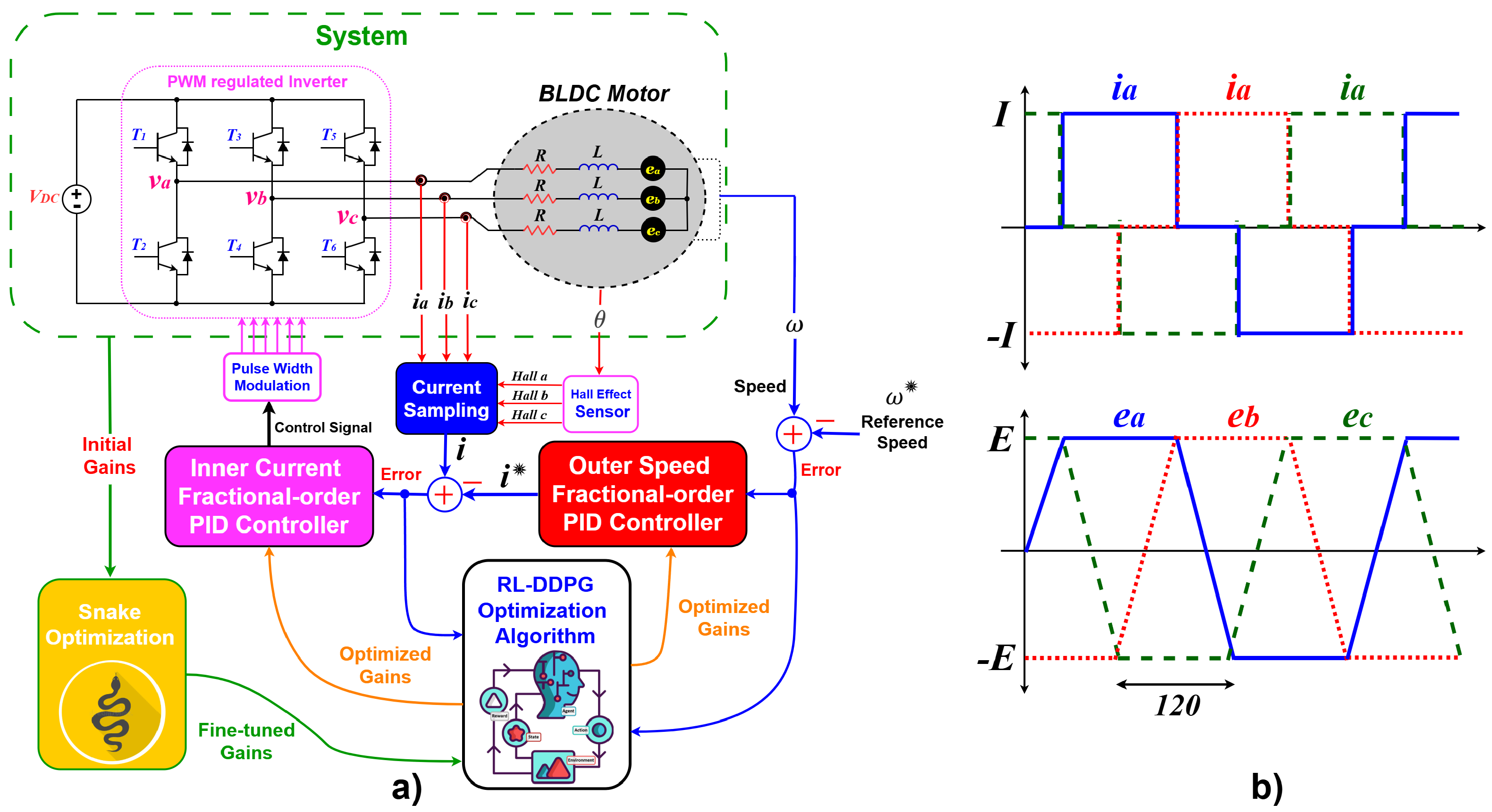
Figure 1 shows the overall design of the test system with BLDC and the controller. Our work has the following main contributions:
FOPID control strategy has been developed and implemented in cascade form to control speed and current of the motor. The method is not only less prone to error, and guarantees proper monitoring, but it also offers better disturbance rejection, especially when subjected to parametric variations and noise without affecting the stability of the system.
Using RL to adaptively optimize FOPID controller gains in real-time using the DDPG algorithm to improve robustness and tracking performance of the BLDC motor without necessarily having to model the system accurately.
The SOA is used as an evolutionary computation method to find the best parameters of the system and reduce the number of conflicts. This leads to an increased convergence rate and adaption to the system frequency behavior.
Real-time testing in HIL setups gives the system a high level of validation in the simulation and experimental conditions, which makes the results more credible and practically applicable.
2. BLDC Motor Modeling
The characteristics of the BLDC motor are challenging to analyze precisely due to the trapezoidal shape of the induced electromotive force of BLDC motors, which have a significant amount of harmonics. To power the BLDC motor, a three-phase inverter is employed, as illustrated in
Figure 1a. The speed controller receives the position and speed information from the BLDC motor through the Hall Effect signals. In order to regulate the motor’s speed and current, this cascade controller comprises two operational loops, also known as the inner and outer loops
Figure 1. Based on the error reported by the speed controller in the outer loop, the current controller generates commutation signals to drive the gates of the power MOSFETs, which in turn regulate the BLDC motor. Based on
Figure 1, the stator voltage equations can be expressed in the a, b, and c coordinate as [
38,
39,
40,
41,
42]:
where
R is the stator resistance,
are the phase voltages,
L is the stator inductance,
are the phase currents,
is the rotor electrical speed,
is the rotor electrical angle, and
are the back EMFs of each phase. Looking at Equation (
1), the initial state space model can be written as [
37]:
Electromagnetic torque is a crucial component of the BLDC motor’s performance. It is defined based on the interaction between the back EMF and the phase currents, which convert electrical energy into mechanical torque. Electromagnetic torque can be defined below [
39]:
where
P is the number of poles, and
is the rotor mechanical speed. Using the linearized model, the electromagnetic torque becomes [
41]:
Actuated by the torque in Equation (
4), the rotor motion can be described as below:
where
denotes the torque function of
and
J,
D, and
are the moment of inertia, damping coefficient, and the load torque, respectively. From Equations (4) and (5), the dynamic equation representing the synchronization error between the rotor and the stator can be derived as [
43]:
where
is the synchronous speed. Henceforth, the problem of stability analysis for the BLDC motor in the open-loop operation mode can be transformed into the qualitative study on the nonlinear ordinary differential Equation (
14).
The relationship between the electrical angle
and
in BLDC motors is a standard identity based on the number of poles. It is given by [
41]:
Rewriting the electrical dynamics, we get:
where the back-EMF terms are defined as:
Equation (
9) represents the dynamic equations of each phase of the BLDC motor. The left-hand side correctly expresses the time derivative of the phase currents. The back-EMF terms
are modeled as proportional to the angular speed and shaped by the position-dependent function
, which approximates the trapezoidal waveform.
The back EMF is proportional to the rotor speed and depends on the rotor’s position:
In which,
is the back EMF constant. In order to facilitate the design of control, the nonlinear model is linearized about a steady-state operating point. This system in state-space form is [
37,
38]:
where:
In Equation (
13),
means the derivative of
with respect to
. For the design and implementation of the proposed controller, the real-time specifications have been considered, focusing on speed regulation in EVs. Key parameters of this motor are listed in
Table 1 to ensure relevance to practical performance conditions.
It is important to highlight that, in order to achieve a realistic representation of the converter behavior, parasitic elements were incorporated into the HIL model. Specifically, parasitic resistances were considered in the transformer windings and inductors. These resistive losses ensure that the simulation environment closely replicates the practical operating conditions of the BLDC motor, thereby improving the reliability and accuracy of the obtained experimental validation results. By accounting for these parasitic elements, the proposed controller’s robustness was validated under more realistic and non-ideal system dynamics.
3. Stability of Open-Loop Operation for BLDC Motor System
For the purpose of open-loop stability analysis, the motor equations are transformed to the rotating dq-rotor reference frame using Park’s transformation. Using the transformed dq variables, the electromagnetic
in Equation (
3) for a round-rotor machine can be expressed as [
1]:
where
and
are stator currents in d-q frame. Higher-order harmonics of rotor flux are neglected in this equation. For round PMSMs, only the quadrature component of the AC currents (i.e., iqs) contributes to the torque. Hence, considering the mean value of
stator current [
43], the mean electromagnetic torque can be achieved as:
where:
: Peak flux linkage of the rotor’s magnetic field, representing the maximum magnetic coupling between rotor and stator,
i : Stator phase current,
: Commutation angle error, representing the alignment between the rotor’s magnetic field and the stator’s current field.
Effectiveness of torque generation is determined by the term in . An ideally aligned system () provides maximum torque, whereas misalignment () decreases the amount of torque and affects stability. These equations emphasize the dependence of the torque on the orientation of stator current and rotor magnetic flux and the effect of the misalignment of the commutation angle on the generation of the torque.
If the electromagnetic torque
is replaced with its mean value
, the error dynamics (5) of the open-loop operation mode for BLDCMs can be changed into
Obviously, the error dynamics in (17) is nonlinear. For the stability of nonlinear dynamical systems, various results have been derived in [
44,
45]. For convenience, the stability of Equation (
17) can be analyzed by using the Lyapunov indirect method.
Stability Conditions
The stability of the open-loop system depends on the ability of to counteract and viscous damping. The system exhibits the following behavior:
Unstable Dynamics (Advanced Commutation, ): When , is reduced due to misalignment. Insufficient torque generation causes the system to decelerate uncontrollably, leading to instability.
Stable Dynamics (Retarded Commutation, ): When , torque generation is favorably aligned, providing sufficient force to counter and damping. The system becomes asymptotically stable, though transient responses may be slower.
Marginal Stability (Accurate Commutation, ): When , torque generation is maximized. The system reaches equilibrium where . While this configuration is ideal for steady-state operation, it is highly sensitive to disturbances, resulting in limited robustness.
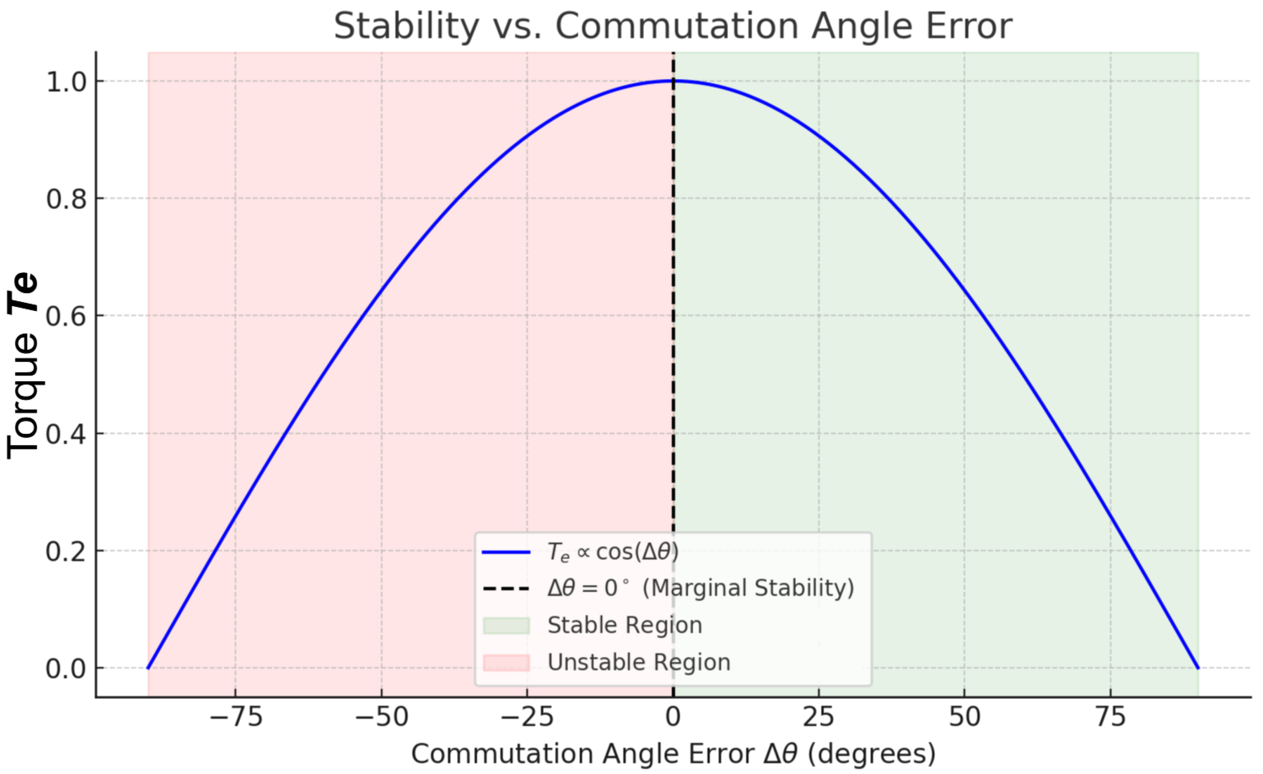
Further to explain the stability implication of commutation angle error,
Figure 2 shows a graphical representation of the torque behavior with respect to
. As indicated, the maximum torque is obtained when
, which is marginal stability. When
the system is stable as the torques are aligned positively, and when
the system is unstable because the torques are aligned negatively, or reduced in magnitude. This visualization helps the theoretical classification of dynamic behavior in the open-loop operation of BLDC motors.
4. Controller Design
4.1. Fractional Calculus
The FOPID technique is an extended version of the conventional PID, improved by applying the fractional method. This controller’s main advantage is the additional degree of freedom applied by two additive parameters, which improves design flexibility [
12]. This concept is designed based on linear filters, while the lower and upper levels of the operator are established using
b and
, which shows the order of integration or differentiation. Here, a generalized transfer function is developed to better demonstrate the FOPID controller:
The values and indicate the pertinent controller parameters. It is clear that the differ-integral order function contains additional terms and . It is evident that and are extra terms in the differ-integral order function. These five parameters are essential to the effectiveness and performance of the task and must be chosen as the best options. We have incorporated the RL-DDPG algorithm into the suggested controller to increase its flexibility to different disturbances. This approach is described in the next section.
4.2. Reinforcement Learning-Based Adaptive Gain Tuning
Reinforcement Learning (RL) has become a strong, model-free technique of control in nonlinear and complex settings [
20]. Within the proposed control structure, RL is utilized to adaptively adjust the gains of a FOPID controller applied to both the speed and current regulation loops of a BLDC motor drive: the gains of the FOPID controller are the gains of the
and
gains. This adaptive controller is learned-based and could keep the controller in optimal performance in different operating conditions, such as parameter changes, load disturbances, and voltage variations. The RL problem is modeled as Markov Decision Process (MDP) with the control system modeled as a tuple of (
S,
A,
R,
) [
21]. In this case, the state space is represented by S, the action space by A, the reward function by R and the discount factor (balancing between immediate and future rewards) by
in [0, 1].
In this work, the state vector is defined minimally as:
where,
e(
t) represents the instantaneous control error (either speed or current), and its first derivative. This concise representation will provide efficient learning and will incorporate the key dynamics of the system. The RL agent output is the action vector:
which is directly proportional to the controller gains used on FOPID structure. The non-integer orders
and
are fixed during the training and execution phases to minimize the complexity of computation. A scalar reward is computed at every time step to steer the learning process as:
where
u(t) is the control effort and
,
,
and are positive scalar weights. This reward formulation is a penalty on tracking error, aggressive transients and control saturation, which promotes smooth and accurate system regulation.
The aim of the RL agent is to find a deterministic policy
that maximizes the expected cumulative reward:
Deep Deterministic Policy Gradient (DDPG) Integration
The Deep Deterministic Policy Gradient (DDPG) algorithm is used to implement the above RL framework in a continuous action space. DDPG is an actor–critic and model-free reinforcement learning algorithm, which is specifically targeted at continuous control problems. It has a deterministic policy (actor) and a learned value function (critic), and it allows gradient descent to update the policy stably [
31]. The actor network is a mapping of the observed state
st to a set of controller gains
at = [
KP,
KI,
KD]. Simultaneously, the critic network
Q(
st,
at |
θQ) estimates the expected return in order to determine the quality of the chosen action. The two networks are deep neural networks and they are trained in parallel.
To make learning stable, DDPG employs an experience replay buffer to keep a history of transitions (st, at, rt, s(t+1)). Mini-batches are randomly selected at every training step out of this buffer so as to decorrelate observations and minimize variance. Also, target networks (and Q′), which gradually follow the weights of the main networks, are used so as to avoid sudden policy changes, and to guarantee convergence.
The critic network is trained with the objective of reducing the temporal-difference (TD) error:
The actor is updated using the sampled policy gradient:
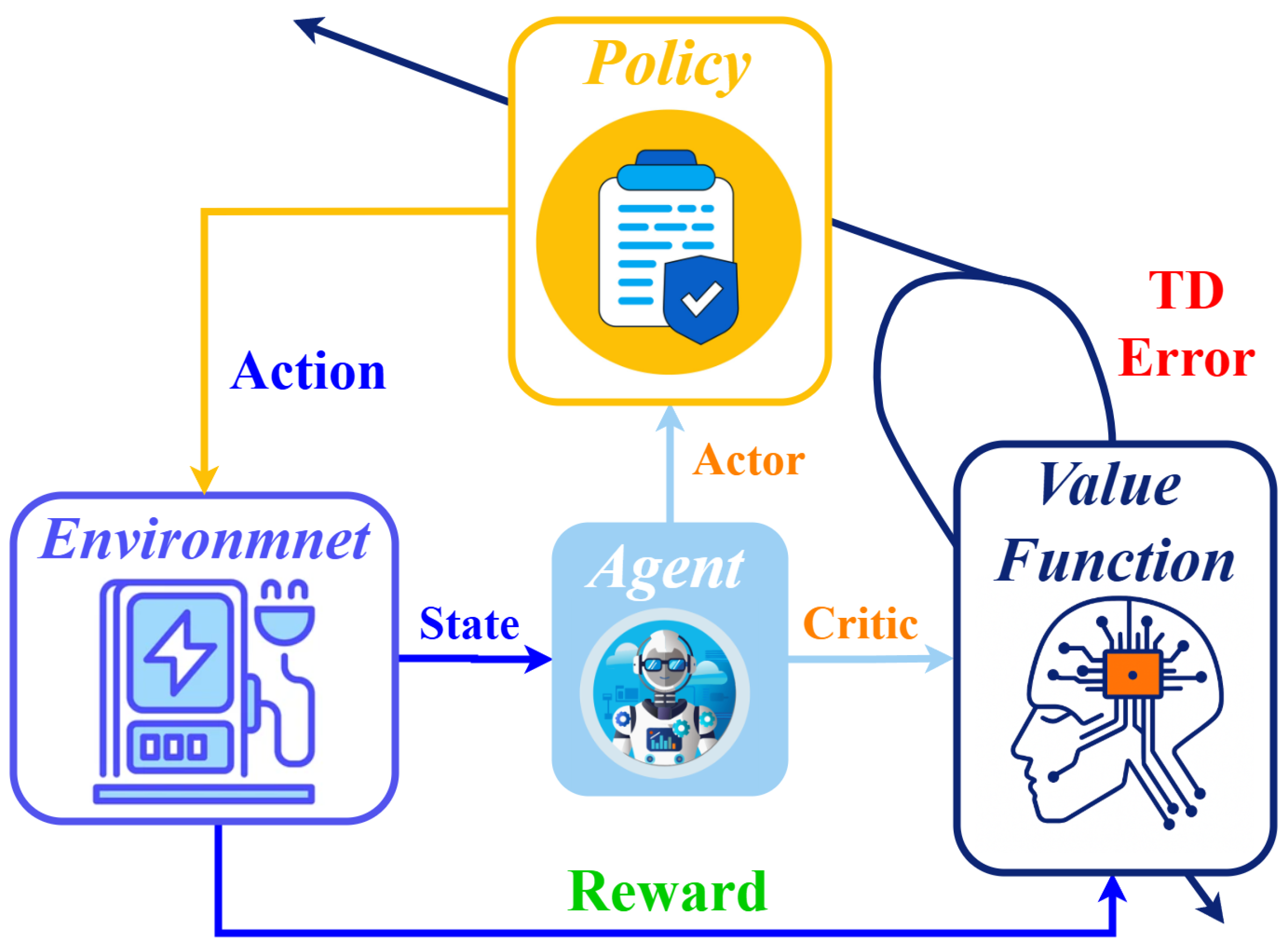
Exploration is promoted during training by introducing noise on the output of the actor with an OrnsteinUhlenbeck process. After the training is over, the trained actor is put in both inner and outer control loops to constantly give fresh gain values. This enables the controller to be flexible to dynamic variation of motor parameters or external disturbances thereby increasing the overall robustness and accuracy of the system. The reward signal, which is depicted in
Figure 3, goes through the environment to the critic.
The proposed system can be made highly autonomous and resilient with the use of DDPG to control the design, eliminating the necessity of manual gain tuning or precise modeling of the plant, and guaranteeing optimal performance under a broad variety of operating conditions.
The hybrid training algorithm proposed in
Table 2 integrates the use of SOA to tune the initial gains of the controller with the DDPG to tune the FOPID controller gains in real-time. Each of those steps, state observation, action generation, reward computation, and updates of the actor and critic networks in different operating conditions, are listed in the table. In order to choose the gain of the controller, we have coupled the controller with Snake optimization to obtain improved results of the controller. The following part explains the Snake optimizer.
4.3. Snake Optimizer Algorithm (SOA)
Snake Optimization (SO) algorithm is a metaheuristic optimization algorithm based on the social and reproductive behaviours of snakes in response to stimuli in the environment. In nature, snakes adjust their behavior- including foraging and mating- depending on the food availability and the temperature. The algorithm simulates this adaptive behavior in order to balance exploration (exploring new regions of the solution space) and exploitation (optimizing known good regions). Mating is a priority when environmental requirements like low temperature and availability of food are met. In this stage, male snakes are competitive in efforts to attract a female and the female can decide to mate or not. When mating takes place, eggs are deposited in a safe place and the female leaves after the young ones hatch.
These biological mechanisms are mathematically translated into mathematical operators in the context of optimization. The exploration phase is based on individual food-seeking process with no mating conditions, when snakes move randomly within the search space to find new solutions. When environmental indicators are favorable, the exploitation phase simulates localized searching and competition, as in the case of male snakes competing to mate, so that the algorithm can refine solutions around known optima. The active alternation of these two phases depending on the environmental thresholds allows SO to prevent premature convergence and keep diversity in the population. Such bio-inspired flexibility results in the Snake Optimization algorithm being very useful in solving nonlinear, multidimensional, and constrained problems, including tuning controller gains in power electronic systems. An illustration of the flow of the algorithm and steps of its work is presented in [
32]. In order to support the selection of the SOA in this research quantitatively,
Table 3 compares it in detail with four popular optimization algorithms: GWO, ALO, PSO and GA. The criteria used to evaluate it is the convergence iterations, final Integral of Absolute Error (IAE), standard deviation (as an indicator of solution stability), parameter sensitivity, CPU time and final fitness value. As demonstrated, SOA provides the lowest IAE and the best robustness with minimal CPU overhead, and therefore, it is possible to tune parameters of the controller quickly, accurately, and stably. This renders it particularly useful in such areas as real-time motor control and adaptive converter systems.
Also,
Table 4 presents the specific algorithmic parameters and internal parameters used in the configuration of the Snake Optimization Algorithm (SOA) to optimize the controller gains, with a balanced trade-off between the convergence speed, solution diversity and robustness.
To show the superiority of the proposed method to other classical methods, four other controllers are implemented, and their results will be compared with this work, including, a single-loop PID and PI controllers optimized with PSO algorithm, a cascade PID controller optimized by SOA and a cascade FOPID optimized with PSO algorithm.
Table 5 shows the gains used for the controllers.
4.4. Closed-Loop Stability Analysis of the System
This section presents a powerful closed-loop control architecture of the BLDC motor that will have cascaded FOPID controllers on speed and current loops. Through the flexibility of FOPID controllers, the system has a better control accuracy and dynamic performance and hence it is suitable in challenging motor control applications. The control system has a cascaded structure to provide the best operation. Speed is controlled by the outer loop, which takes the error in speed and the actual motor speed and a FOPID controller to produce a reference current to the inner loop. The inner loop calculates in conjunction with the measured motor current to generate control signals to the PWM inverter that drives the motor.
In order to examine and show the stability of the closed-loop system,
Figure 4 shows the cascaded control system with FOPID controllers. This diagram graphically illustrates how the speed and current control loops interact with one another, the BLDC motor dynamics, and the feedback paths that help to make the system robust and stable.
Figure 4 shows feedback gains as X, Y, Z and U s is the control signal produced by the inner controller. Based on this block diagram, we are able to drive closed-loop transfer function of the system to prove its stability.
The closed-loop transfer function describes the behavior of the system after incorporation of the feedback controller. With a feedback arrangement, the FOPID controller transfer function is multiplied with the open-loop transfer function of the system to generate the closed-loop transfer function. Here is the expression of the closed-loop transfer function:
where,
is the open-loop transfer function of the BLDC motor and
is the FOPID controller for the current loop.
can be defined using the state-space matrices of the system as:
.
The outer loop transfer function corresponds to the speed controller, which regulates the motor speed using the output of the inner loop. The transfer function for the closed-loop system can be given by:
Using the values defined for each transfer function, the following closed-loop transfer function can be reached:
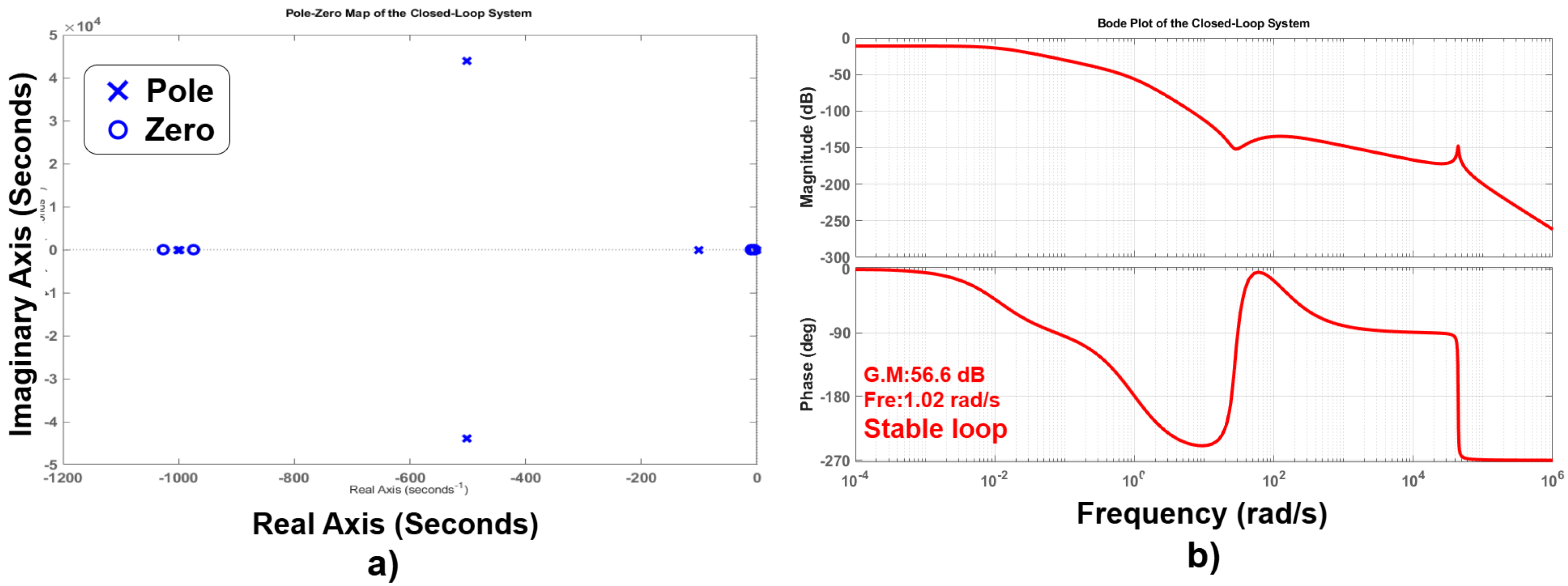
Figure 5 shows the performance and stability analysis of closed-loop system with the designed cascade FOPID controllers. As shown in the pole-zero map in
Figure 5a, the system is stable since all the poles are in the left half of the complex plane indicating a good damping. The zero distribution complements the poles and this helps in improving the transient performance. Further confirmation of the system stability and robustness is through the Bode diagram in
Figure 5b where the gain margin (G.M.) is 56.6 dB and phase crossover frequency is 1.02 rad/s. These measures show that it has adequate margins to be stable even in the presence of perturbations or uncertainty in the system. The high frequencies are attenuated smoothly in the magnitude plot indicating good noise rejection and the phase plot verifies that the closed-loop dynamics have suitable phase characteristics. Collectively, the analyses confirm the robustness and efficiency of the closed-loop system that is attained using the cascade control structure.
7. HIL Simulation Results
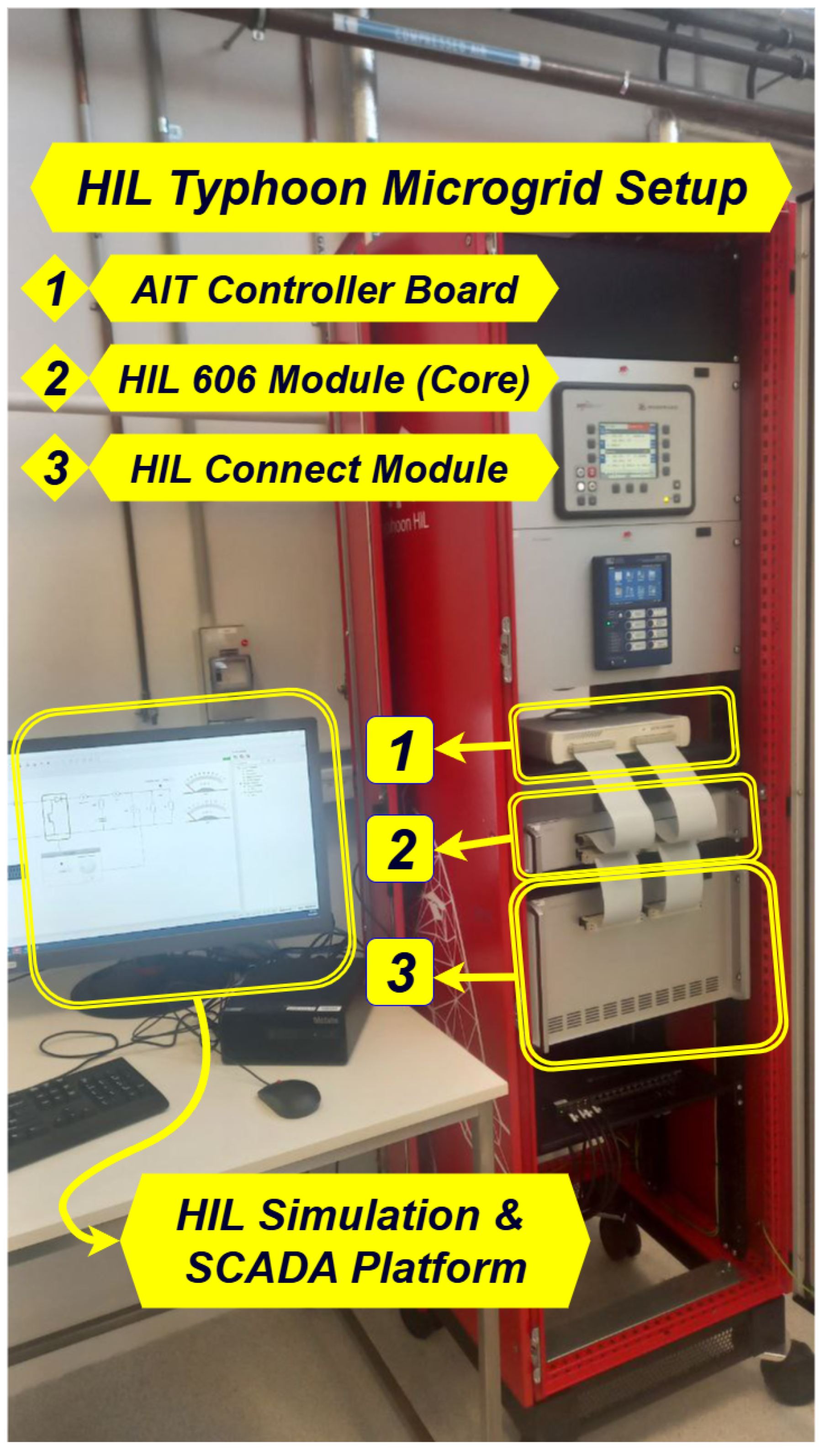
This configuration speeds up development, improves safety, and offers a real-time evaluation of system reaction and stability. The Supervisory Control and Data Acquisition (SCADA) environment and HIL simulation used in this investigation are shown in
Figure 11. The online platform for the BLDC motor with the suggested speed controller is displayed in
Figure 11a, and the real-time SCADA platform for the online results is displayed in
Figure 11b. This real-time testing setup is used to test various scenarios in order to assess the effectiveness of the suggested controller for BLDC’s speed regulation. The specifics of this technique are explained in [
23].
7.1. Case 1: Tracking Performance
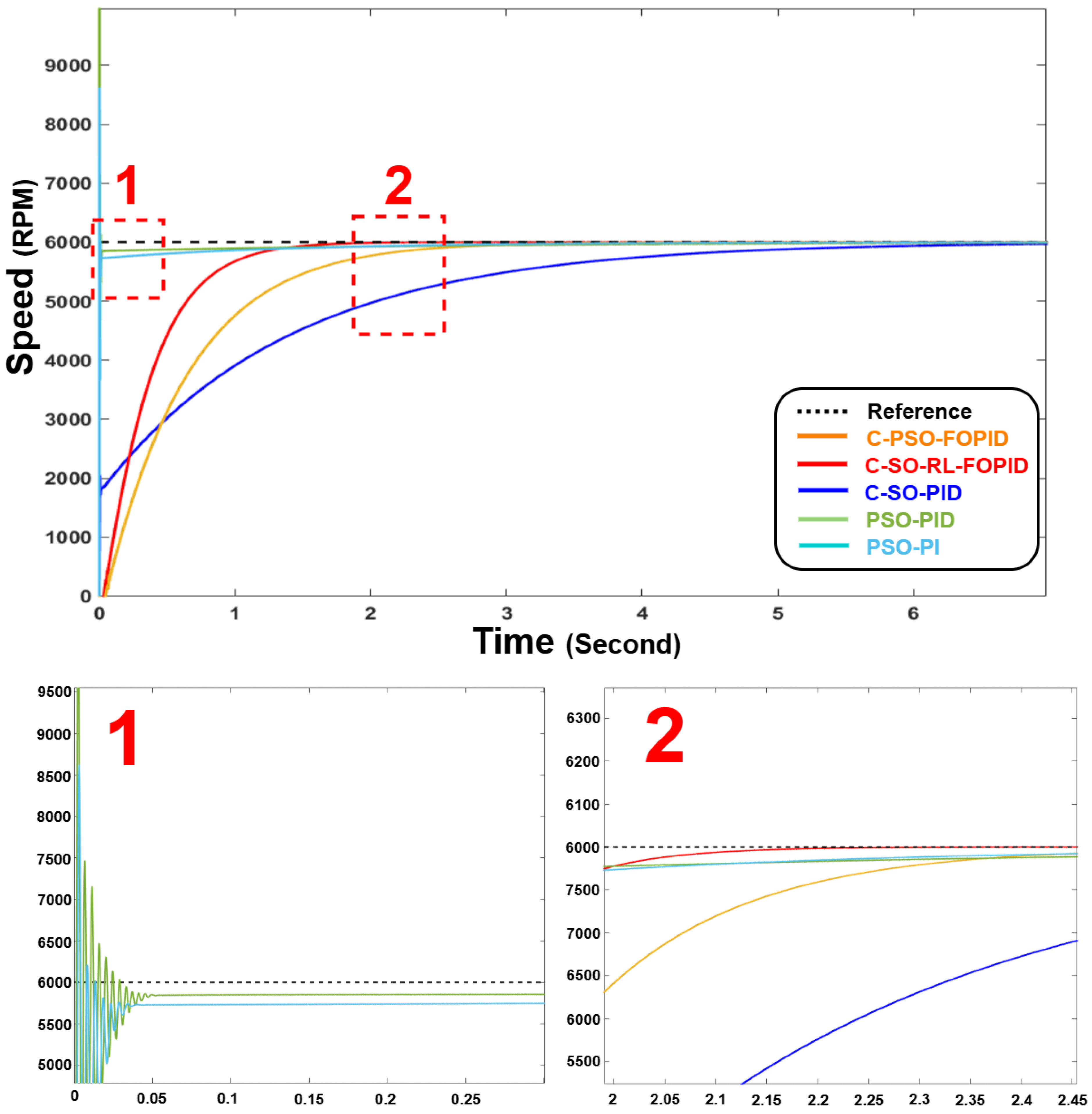
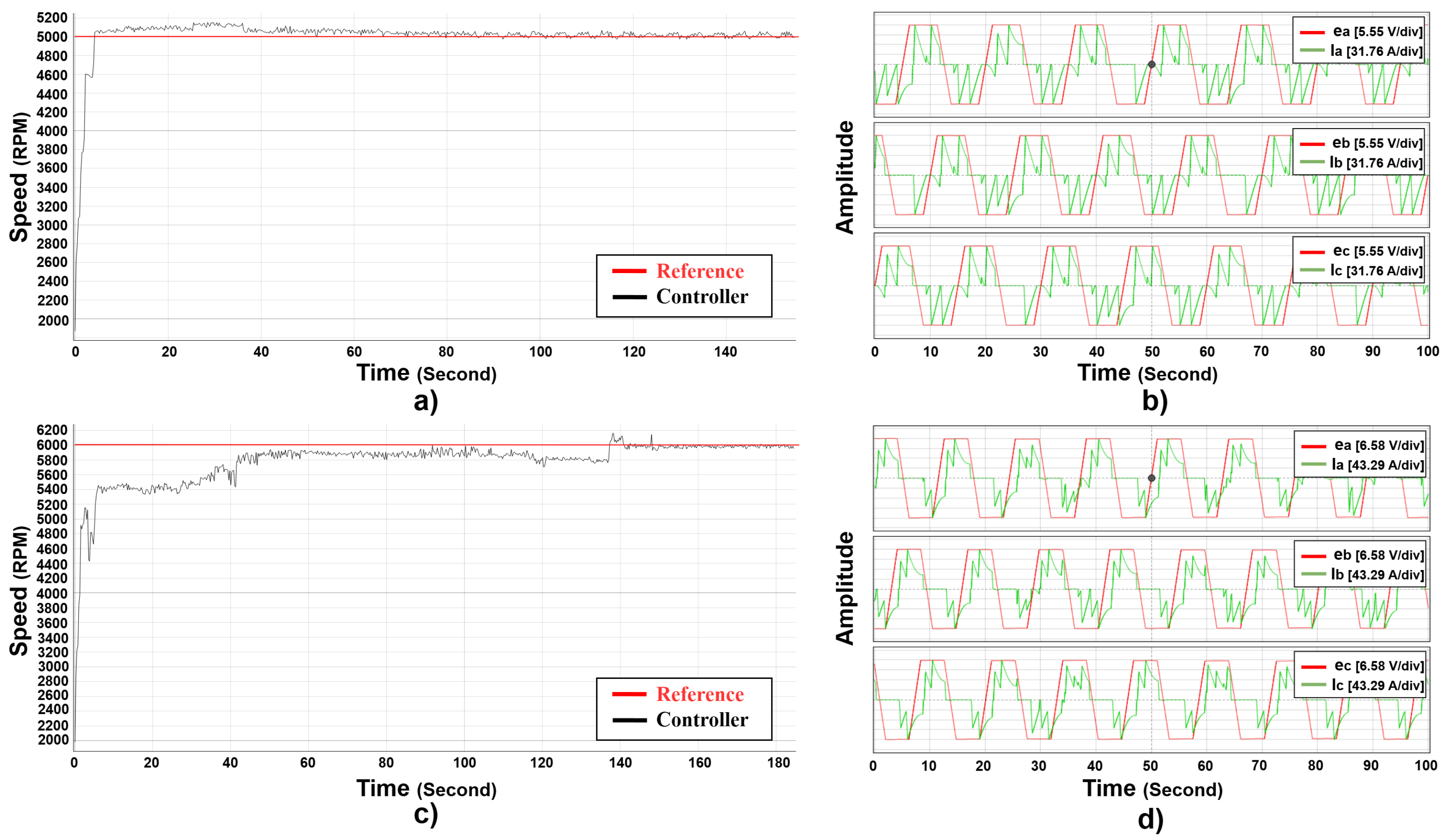
Firstly, to examine the performance of the proposed controller in the real time environment, the references of 5000 RPM and 6000 RPM are tracked by the controllers with no disturbances (
Figure 12) with 350 V supply voltage. In addition, to better understand the impact of current on all phases and the level of back EMF for each phase, these components are shown for the proposed C-SO-RL-FOPID controller’s output.
Figure 12 shows the results of the C-SO-RL-FOPID controller that has been designed to track the speed of a BLDC motor at two speeds 5000 RPM (top) and 6000 RPM (bottom) (
Figure 12a,c). The left-hand graphs illustrate how the controller tracks the reference speed and the right-hand graphs illustrate the currents and Back EMF of the three phases of the motor. As is illustrated in both examples, the proposed controller is able to track a desired speed with a smooth and stable manner, with little overshoot and no noticeable steady-state error, demonstrating the effectiveness of fractional-order control in the control of complex dynamics. Also, the RL algorithm is essential in the optimization of the gains of the FOPID controller. The RL algorithm guarantees that the controller will have an optimal response in terms of speed tracking, current regulation, and overall stability by optimising the controller parameters. SO tuning can be used to tune the controller to better follow the nonlinearities and disturbances of the system and lead to a well-coordinated control strategy of the current and speed loop. The right figure (
Figure 12b,d) also proves the robustness of the controller, since the currents (
) and Back EMF signals (
) are well regulated, despite the motor being operated at varying speeds. The controller has consistent waveforms with very little distortion, which points to its capability to work under different operating conditions without affecting the performance of the motor. As a result, the cascade control, FOPID methodology, and the SO algorithm combination provides high performance in speed tracking, current regulation, and stability of the BLDC motor. It is a very efficient solution to the challenging motor control applications because the fractional-order control increases the flexibility of the controller, and the SO algorithm improves its performance.
The present waveforms in
Figure 12b,d represents the three phases of the BLDC motor at 5000 RPM and 6000 RPM respectively. The currents are aligned correctly with the trapezoidal back-EMF waveforms, which means that commutation works. The controller proposed ensures that there are smooth and symmetrical current profiles in all phases and the distortion or ripple is minimal. This proves that the inner current control loop is well damped in steady-state operation. Also, there is no current spike or asymmetry, which indicates that the system can effectively suppress switching transients and handle inverter switching losses.
It is important to mention that the back-EMF waveforms shown in
Figure 12 are obtained based on mathematical model with ideal conditions and serve as theoretical shape of
. In practice, back-EMF signals have small distortions caused by current ripple and inverter switching. These effects are not graphically represented in this plot; however, they were considered in the HIL environment by modeling inverters in detail and coupling signals. The performance of the overall controller in these non-ideal conditions has been confirmed by real-time testing.
7.2. Case 2: Variable Speed Tracking—Controller Performance Evaluation
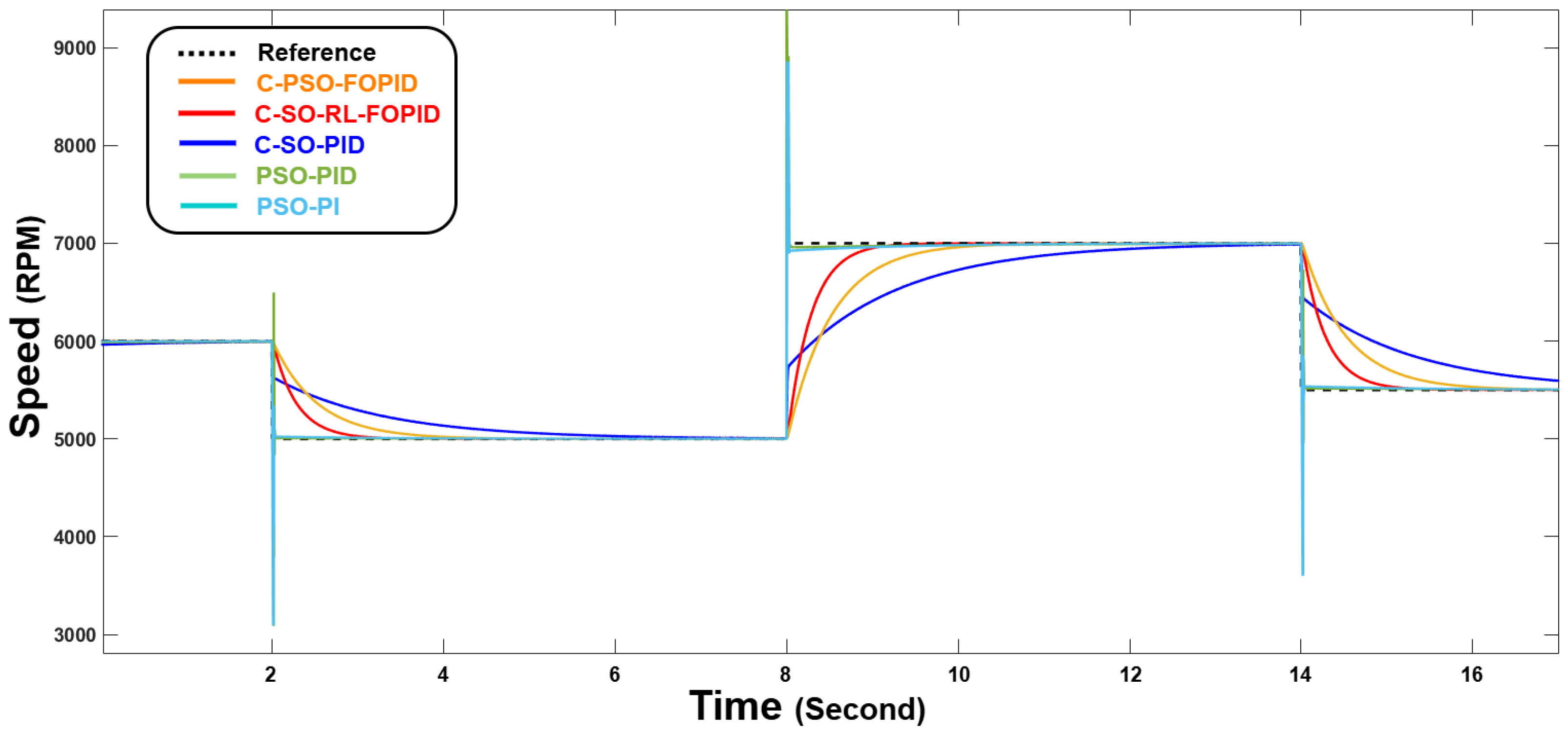
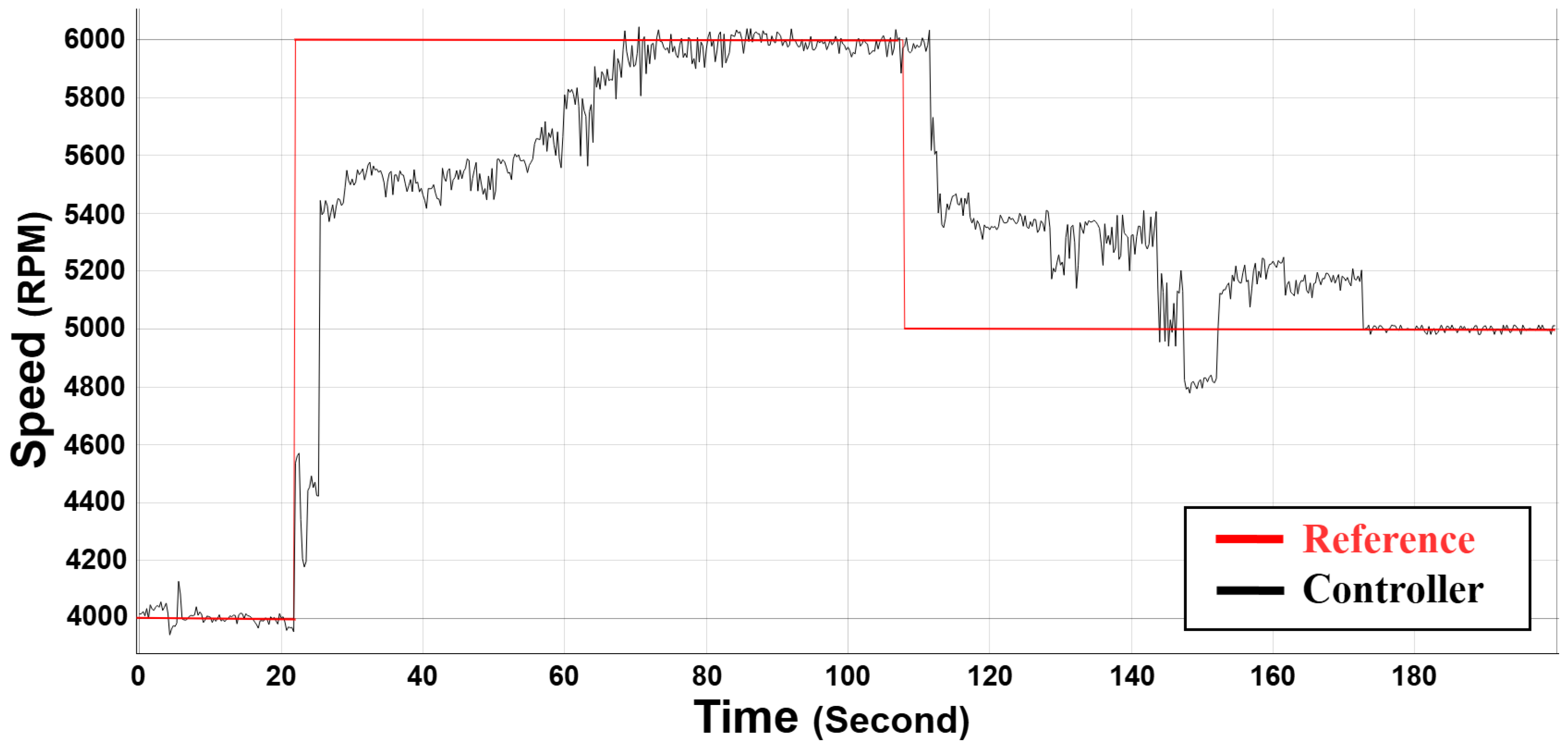
Figure 13 illustrates the real-time operation of the proposed cascade controller used to track speed of a BLDC with different speed references, conducted through a HIL system. The graph displays that the motor speed (red line) tracks the reference speed (black dashed line) with different changes in speed setpoints and therefore demonstrates that the controller is very accurate and responsive. The motor speed tracks the reference with little deviation and no major overshoot which demonstrates the effectiveness of the C-SO-RL-FOPID controller in real-time applications. It is thus an effective and efficient motor control solution in the real time application, especially in the industrial high demand setting.
7.3. Case 3: Supply Voltage Variation Tracking: Controller Performance
Another scenario that could demonstrate the robustness of this method is the modification of the supply voltage level. In the next case, the impact of supply voltage variation has been tested to ensure the stability of the system against this scenario.
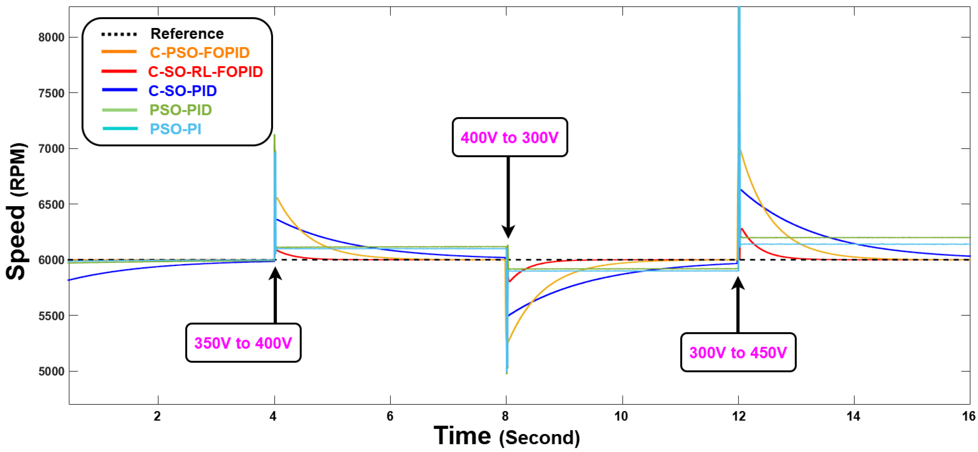
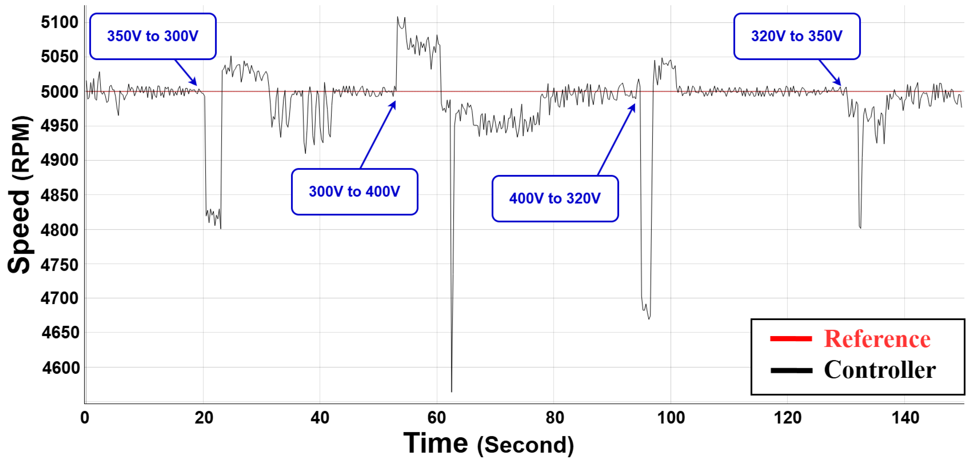
Figure 14 shows the performance of the controller in handle this disturbance under various levels.
The proposed C-SO-RL-FOPID controller has been shown to be highly robust to abrupt changes in the supply voltage as shown by the HIL outcomes. Through sudden variations of the input voltage between 300 V and 450 V the controller is always able to control the speed of the motor around the reference of 5000 RPM with little variation. The controller manages to overcome these disturbances and keeps the speed at a very tight range and recovers quickly after every voltage change. This proves the high robustness of the controller to cope with the unpredictable variations in supply voltage so that the motor can be run reliably and stably over the actual operation environment despite the large external disturbances.
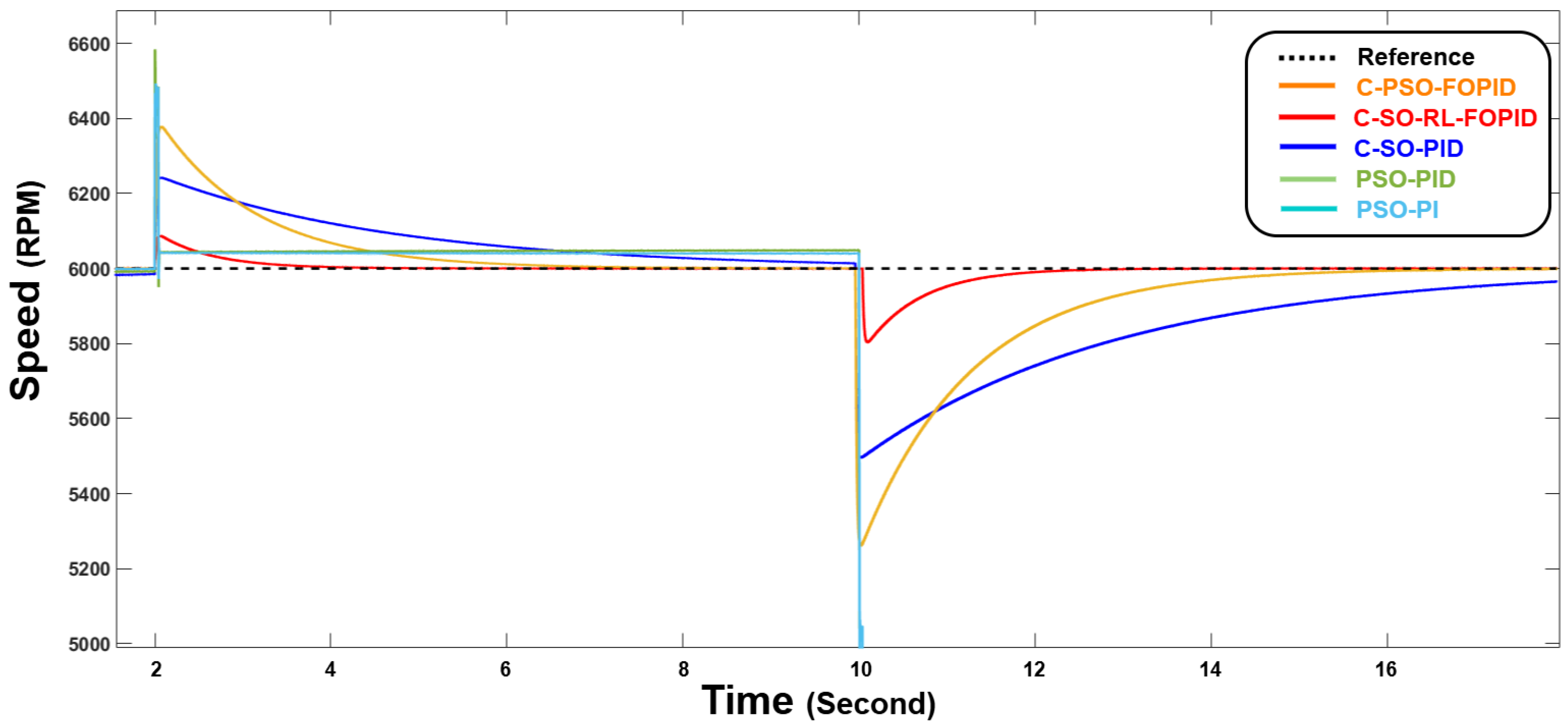
The industrial settings, in which the motors are operated, do not have ideal conditions; hence, the probability of dynamical changes on the motor is high. In order to re-establish the high efficiency and strong dynamics of this controller in real time applications, abrupt parametric changes are tested in
Figure 15.
7.4. Case 4: Load Variation-Controller Performance Tracking
The
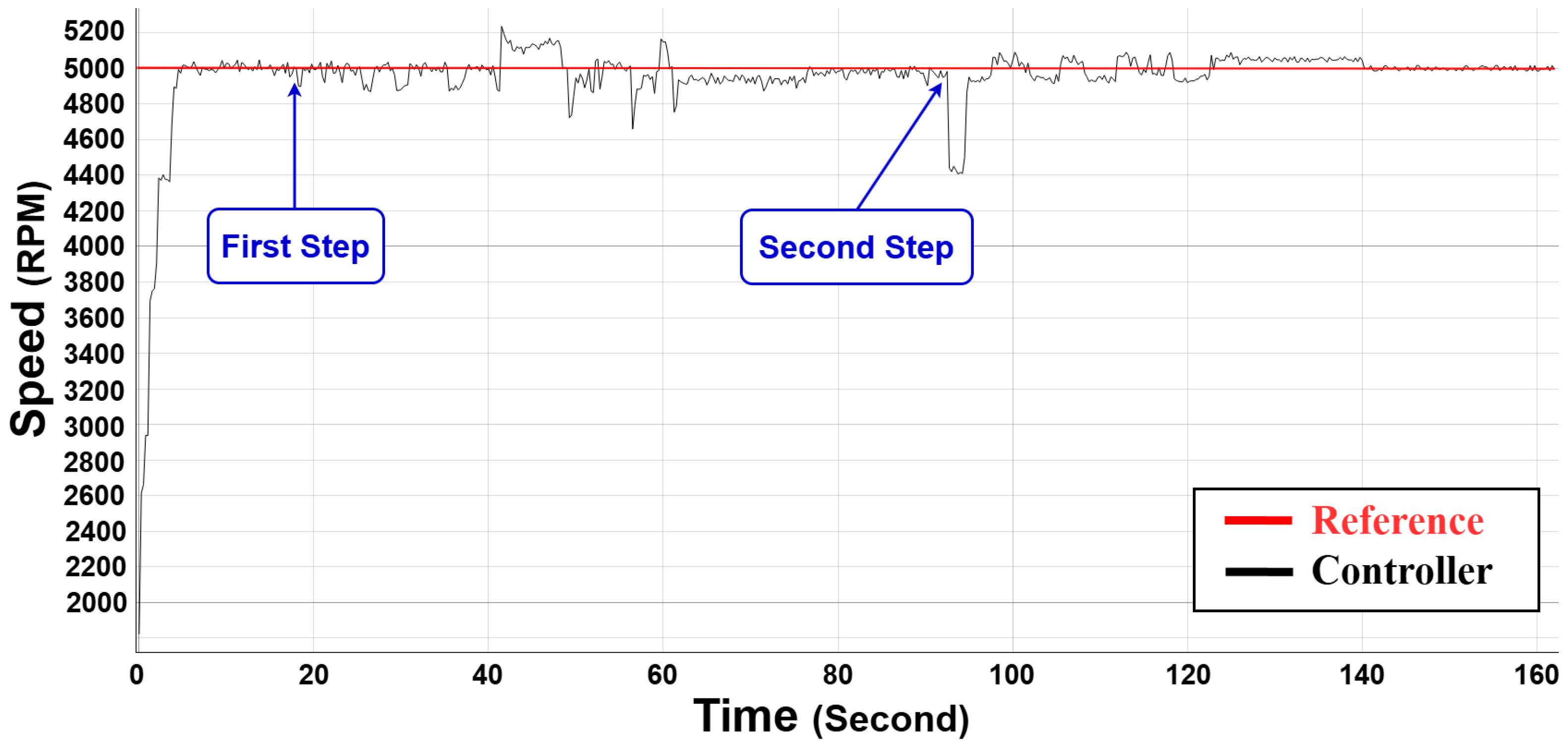
Figure 15 shows the real-time simulation outcomes of the BLDC motor with the proposed C-SO-RL-FOPID controller with two different parametric changes. The two marked steps, First Step and Second Step, are the instances where internal resistance and inductance variation were added to evaluate the capacity of the controller to regulate the speed. The controller is able to follow the reference speed with robustness and stability even in the face of the disturbances added.
7.5. Case 5: Noise Impact
In practice, the EV motor control systems are usually susceptible to all kinds of disturbances and noise, either due to the environment, electromagnetic interference, or sensor errors. The robustness of the controller when subjected to these noisy conditions is important to be able to obtain stable and reliable performance in practice. This case study examines the behaviour of the suggested C-SO-RL-FOPID controller in the presence of sudden noise disturbances.
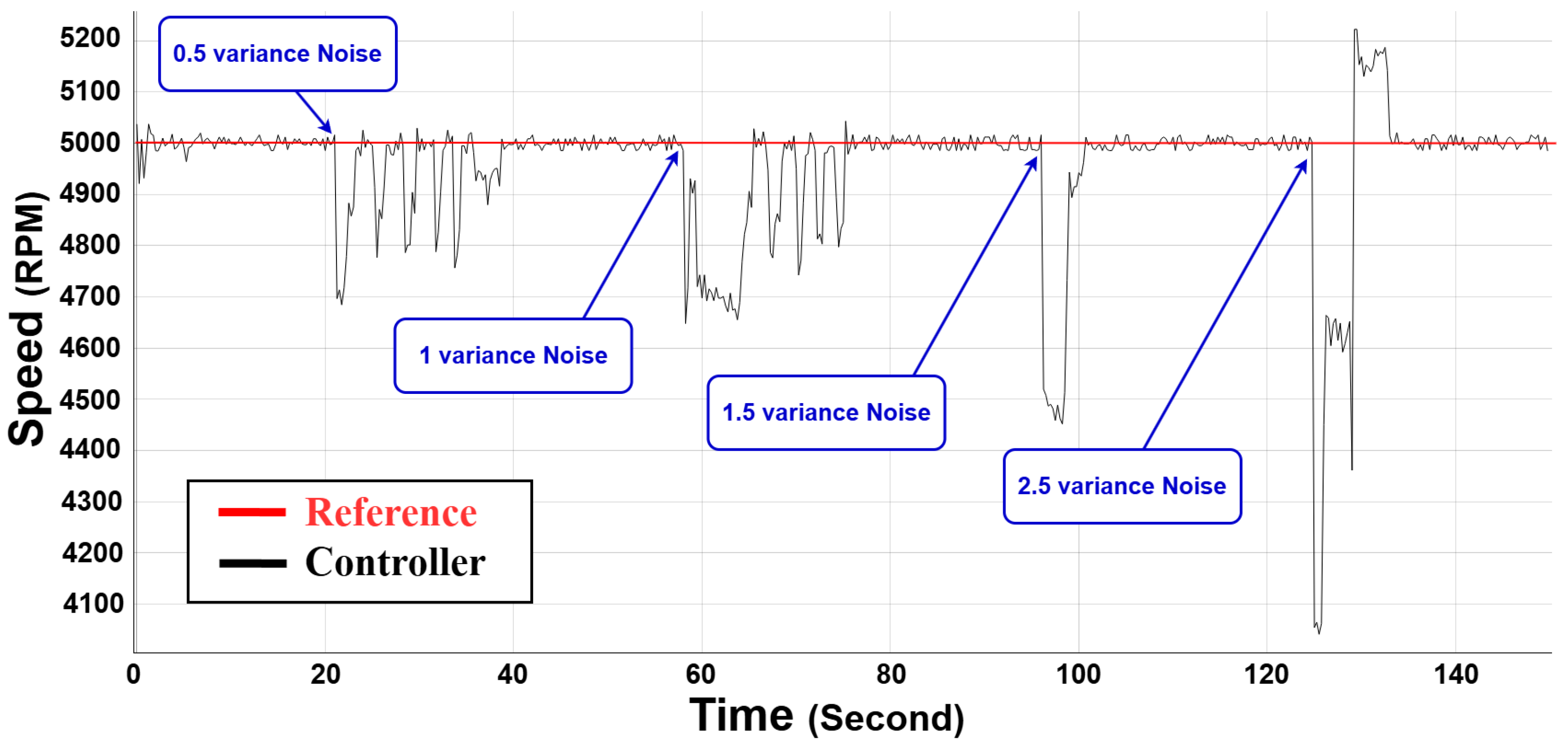
Figure 16 shows the strength of the suggested controller in noisy environment.
The BLDC motor was operated with a fixed reference speed of 5000 RPM, and noise with varying variances (0.5–2.5) was added at varying time intervals to reflect the noises in the real world. With noise variance of 0.5, the controller was able to hold a stable speed near the reference with high noise rejection with slight variations. When the variance of the noise was set to 1, the fluctuations in speed were more significant, but the controller reduced the deviations successfully and returned to stability fast. The greatest deviations were recorded at the largest noise variance of 2.5 whereby there were occasional sharp falls and spikes in speed. In spite of these drastic variations, the controller was able to settle the motor speed following every disturbance, and this suggests a high level of robustness. These findings indicate that the controller is efficient in managing moderate levels of noise and that, although the controller is effective in managing a high level of disturbances, adaptive improvements or extra filtering techniques might be required when dealing with extreme noise levels. In general, the paper proves the reliability and the applicability of the Cascade SO-RL-FOPID controller to real-life EVs and provides the future directions of improvements in the performance of the controller. The cascade SO-RL-FOPID controller has been found to be much more reliable, robust, and adaptive than other controllers as shown by the experimental results in different scenarios. Its performance makes it the best and most versatile alternative in any test carried out. In order to underline the benefits of this method even more, the next section will present a thorough comparison of the main features and assessment criteria among various controllers.
It is necessary to mention that the dynamic performance of the system that can be seen in the real-time Hardware-in-the-Loop (HIL) environment has minor differences with the results of the offline simulation. The differences are mainly attributed to the fact that such non-idealities as signal sampling delays, switching transients, and parasitic effects are included in the HIL platform but are generally not present in idealized MATLAB/Simulink simulations. In addition, real time control hardware will add quantization and processing delays, which will influence current loop accuracy and transient timing. In spite of these differences, the general control goals such as fast tracking, low overshoot and high response to disturbances are still attained. The fact that the trend and behavior are consistent proves the practical feasibility of the proposed controller.
8. Discussion
Although the suggested controller incorporates more progressive ideas like fractional calculus and RL, it is necessary to explain that the general framework is highly computationally efficient and practically feasible to real-time implementation. The core controller is a typical cascade PI structure, and the only two extra degrees of freedom are added by fractional-order operators in the form of low-order filters. These filters are chosen so that they are accurate and yet place a minimum computational load. SOA is used in the offline stage to initialize the controller gains. The method is a metaheuristic approach that guarantees global exploration at the early tuning phase yet does not add to the computational burden at runtime. To achieve online adaptability, a DDPG agent is added to real-time update the PI gains. Although this adds more computation, the learning agent is a modular block of optimization that revises the controller parameters at a set period of time based on state-feedback. The RL block is implemented to operate in parallel with the main control loop and is optimized in order to converge efficiently with a compact neural network structure. The feasibility of the suggested method has been proved in practice with the help of the Typhoon HIL 606 platform. The findings indicate that the system was able to process real-time signal acquisition, learning-based adaption, and control computation without degrading stability or responsiveness. This establishes that the suggested algorithm is not only strong and flexible but also can be applied on real-time embedded control systems. In spite of the integration of the sophisticated elements, including fractional-order dynamics, optimization heuristics, and deep reinforcement learning, the controller is constructed to be robust in the form of modularity and fault tolerance. The inherent PI control structure ensures that the system is stable without real-time tuning, and the extra elements are used to enhance tracking precision, flexibility and disturbance rejection. Moreover, a large number of tests were performed both in simulation and real time to determine the robustness to a large variety of disturbances such as voltage variations, loading variations, parametric uncertainties and noise injection. These tests proved that the suggested approach does not only preserve the accuracy of control but also is capable of responding to the dynamic operating conditions, which proves its stability and resilience in real-life settings.
Novelty Highlight
The originality of this work can be summarized as follows:
Cascade RL-DDPG-SO-FOPID Control Structure—A dual-loop cascade Fractional-Order PID (FOPID) controller is developed, where both inner current and outer speed loops are coordinated. The architecture is enhanced by RL-DDPG and SOA, which is not reported in existing BLDC motor control literature.
Hybrid Initialization and Online Adaptation—Unlike prior works that rely only on offline tuning or solely adaptive learning, this study introduces a hybrid framework: (i) SOA provides optimal initial gain tuning to avoid poor initialization, and (ii) RL-DDPG continuously adjusts the controller gains in real-time to ensure adaptability under nonlinear, uncertain, and dynamic EV conditions.
Hardware-in-the-Loop Validation—The proposed RL-DDPG-SO-FOPID controller is implemented and tested on a Typhoon HIL 606 real-time platform, which incorporates non-idealities such as parasitic elements, delays, and switching transients. This ensures practical feasibility beyond conventional MATLAB/Simulink-based studies.
Extensive Robustness Testing—The controller is validated under diverse scenarios including abrupt reference speed changes, voltage disturbances, parametric uncertainties, load variations, and noise injection. Results confirm that the RL-DDPG-SO-FOPID controller offers superior adaptability, tracking accuracy, and robustness compared with classical PI/PID and metaheuristic-based controllers.
In summary, this work presents the first cascade RL-DDPG-SO-FOPID control scheme for BLDC motor drives, establishing a novel hybrid adaptive control strategy that is both theoretically innovative and practically validated for EV applications.
9. Conclusions
Finally, this paper proposes a powerful and smart control strategy of BLDC motors, which is founded on a cascade fractional-order PID (FOPID) controller. The suggested dual-loop structure overcomes the shortcomings of traditional PID controllers to deal with the nonlinearities, parameter variations, and dynamic dynamics that are characteristic of BLDC motor systems. The cascade structure makes the system much more responsive, stable, and able to reject disturbances over a wide range of operating conditions by separating control tasks into an inner loop that regulates current and an outer loop that controls speed. The non-integer dynamics of the FOPID controller has a number of benefits over conventional PID methods, such as better noise resistance, more tuning freedom, and control over system uncertainties. To address the issue of the selection of the optimum gain values and adaptation of the same in real time, however, a hybrid learning-based method is proposed. Snake Optimization Algorithm (SOA) is applied to give a good initial set of controller gains so that the training starts off well-conditioned. After that, the RL method with Deep Deterministic Policy Gradient (DDPG) algorithm is incorporated to online adjust the FOPID gains adaptively according to the performance of the system. The combination allows the controller to continually optimize its behavior with respect to varying load conditions, disturbances and non-modeled dynamics. The proposed cascade RL-SOA-FOPID controller is effective, and its effectiveness is proven by the real-time implementation with the Hardware-in-the-Loop (HIL) simulation. Experimentally, it has been shown that tracking is quicker, overshoot is lower and the controller is more robust to variations in supply voltage and parameters than classical and fixed-gain controllers. On the whole, the designed controller offers a very flexible, accurate and stable solution to be used in advanced motor control applications. Although the current validation scenarios involve a wide range of disturbances and dynamic loads, in future studies, standard EV driving cycles, e.g., the EPA UDDS and WLTP, will be used to further test the performance of the controller in realistic operating conditions. Also, the scope of multi-objective or transfer learning-based reinforcement frameworks may be extended to improve generalization and convergence on various types of motors and environments. All in all, the suggested controller presents a realistic, adaptive, and high-performance solution that is applicable in the real-world application of advanced BLDC motor control.
