Article

Development of a Spark-Ignited Combustion Strategy for 100% Ammonia (NH3) Operation in Internal Combustion Engines

1
Intitute of Internal Combustion Engines (IFKM), Karlsruhe Institute of Technology, 76131 Karlsruhe, Germany
2
SEM AB, 662 34 Åmål, Sweden
*
Author to whom correspondence should be addressed.
Energies 2025, 18(19), 5051; https://doi.org/10.3390/en18195051
Submission received: 12 August 2025 / Revised: 5 September 2025 / Accepted: 15 September 2025 / Published: 23 September 2025
(This article belongs to the Topic Clean and Low Carbon Energy, 2nd Edition)

Abstract

Ammonia (NH3) is a promising carbon-free fuel for internal combustion engines, but its low reactivity and poor ignition properties present significant challenges for stable operation. This study presents the development and experimental validation of a spark-ignited combustion process that enables stable engine operation using 100% liquid NH3 as a single fuel. A modified single cylinder research engine, equipped with NH3 port fuel injection and a high-energy capacitive ignition system was used to investigate combustion behavior under various load conditions. The results show that stable, knock-free combustion with pure NH3 is feasible at every operating point without any ignition aids like diesel fuel or hydrogen (H2). The full load conditions of a diesel engine can be represented with an indicated efficiency of 50% using this combustion process. The emission measurements show nitrogen oxides (NOx) and NH3 emissions in a 1:1 ratio, which is advantageous for a passive SCR system. Increased nitrous oxides (N2O) formation occurs at low loads and cold combustion chamber temperatures. This work demonstrates the technical viability of carbon-free NH3 combustion in spark-ignited (SI) engines and represents a promising step towards net-zero combustion.

1. Introduction

International trade heavily depends on maritime transport, which accounts for a considerable share of global CO2 emissions. As part of the effort to reduce Greenhouse Gas (GHG) emissions across all sectors, the International Maritime Organization (IMO) has committed to achieving climate neutrality for sea-going vessels by 2050 [1]. In this context, Ammonia (NH3) has emerged as a promising zero-carbon fuel. It can be combusted without forming Carbon dioxide (CO2) and is already globally available through a well-established infrastructure by the fertilizer industry. Furthermore, NH3 is a viable Hydrogen (H2) carrier and enables more efficient storage and transport compared to H2 [2,3]. Different concepts for supplying NH3 to internal combustion engines have been investigated. Dual-fuel strategies, where NH3 is combined with a carbonaceous pilot fuel (e.g., diesel), improve ignition and flame propagation but compromise the carbon-neutral potential of NH3 [3]. Combinations of NH3 and H2 avoid this drawback and enable stable combustion, yet they require a separate H2 supply, which adds complexity in terms of storage, infrastructure, and safety [4,5,6,7]. Supplying gaseous NH3 eliminates liquid handling challenges but suffers from low energy density and limited engine performance, particularly at high loads. Liquid NH3 fueling, on the other hand, offers higher energy density and improved load capability but raises challenges regarding evaporation, mixture formation, material compatibility, and lubrication [2,8]. These limitations highlight the need to investigate liquid NH3 as single fuel, in order to assess its true potential for achieving net-zero combustion.
Ammonia combustion itself is subject to significant challenges, including a high auto-ignition temperature, low laminar flame speed, and narrow flammability limits [9,10]. Pollutant emissions, in particular NOx, NH3, and N2O, are highly dependent on combustion temperature and mixture quality [8,11,12]. Engine-based investigations highlight the challenges of achieving stable operation across the full load range without pilot fuels [3,13,14]. This context motivates the present study, which focuses on pure liquid ammonia operation without any hydrogen or hydrocarbon assistance.
Switching to carbon-neutral fuels such as NH3 offers the possibility of using existing combustion systems with relatively few changes and thus at low cost. Among the alternative fuels, NH3 offers favorable properties including higher volumetric energy density than H2 (Table 1) [2].
This study presents the results conducted on a Spark Ignition (SI) engine that was operated using 100% liquid NH3 and no pilot fuel. The aim was to explore the possibility of achieving net-zero combustion using NH3 as a single fuel. We seek to understand the ignition and combustion behavior of NH3 in every load point to identify technical boundaries for its use in future marine powertrains. Special emphasis is placed on ignition properties, heat release, efficiency, and emission formation.

2. Experimental Setup

The experimental investigations are carried out on a single cylinder research engine derived from the Liebherr D966 diesel engine (for characteristics, see Section 2.1). The engine, modified as part of the Campfire Alliance project, operates with spark ignition and has been adapted for liquid NH3 fuel. To ensure precise monitoring and control, the engine was installed on a fully instrumented test bench, enabling comprehensive data acquisition with MORPHÉE (Enorise, Trappes Cedex, France) and real-time combustion analysis with with DEWE-800 (DEWETRON GmbH, Grambach, Austria). The test bench also features conditioning for cooling water, oil, and charge air. Both coolant and lubricating oil temperatures were kept at 85 °C throughout all experiments to ensure reproducibility and comparability of the operating points. Charge air heating is applied upstream of the intake manifold using an inline electric air heater to increase the intake air temperature up to 60 °C, which is crucial due to the high enthalpy of NH3 vaporization. Elevated intake temperatures facilitate faster ammonia evaporation, improve mixture homogeneity, and enhance ignition reliability, particularly at low-load conditions. A schematic overview of the setup is shown in Figure 1.
The experiments were performed at steady-state engine operation in three representative load regimes (low, medium, and high). For each operating point, at least 200 consecutive cycles were recorded and averaged to evaluate combustion stability via the Coefficient of Variation (COV) of the Indicated Mean Effective Pressure (IMEP) COVIMEP. The ignition system was alternated between a conventional inductive ignition and a high-energy capacitive system “FlexiSpark” (SEM AB, Åmål, Sweden), allowing a direct comparison of ignition performance with pure liquid NH3 fueling.

2.1. Engine Configuration

The original diesel cylinder head was modified to accommodate a spark plug in place of the diesel injector. A specially designed intake manifold was used, allowing the integration of a dedicated liquid NH3 injector (magnetic injector, nominal injection pressure 20 bar). The intake pressure and temperature are adjusted by an external oil-free compressor system and intake heater to ensure defined boundary conditions. It is passed through a calming volume (volume 200 L) to dampen pulsations. Since the intake manifold does not incorporate swirl or tumble enhancement devices, no additional charge motion is generated to support mixture homogenization. Consequently, mixture formation is predominantly governed by the spray atomization and subsequent vaporization of liquid NH3 under the prevailing intake temperature and pressure conditions. The engine was directly coupled to a dynamometer for controlled variation of load and speed. Engine specifications, including displacement, bore, and stroke, are summarized in Table 2. Due to confidentiality agreements with the engine manufacturer, details such as the exact compression ratio and valve timing cannot be disclosed. Nevertheless, the specifications correspond to those of a typical medium-speed research diesel engine, and are sufficient to reproduce the operating conditions reported in this study.

2.2. Ignition System Configuration

The standard ignition system used at the test bench, here as a reference, is an inductive, industry-standard ignition system.
Former tests on the same single-cylinder research engine demonstrated that higher ignition energy is required to achieve stable operation with pure NH3, particularly at low loads and low in-cylinder temperatures [19,20]. Based on these findings, a capacitive ignition system (“FlexiSpark” from SEM [21]) was implemented as the ignition source. The system consists of an ignition control module (ICM), which includes the primary voltage source and a dedicated ignition coil sitting on top of the cylinder head. Via CAN-connection, the parameters “spark duration” and “spark current” can be adjusted to the user’s desire. A schematic of the ignition system configuration is shown in Figure 2. The system generates a spark with the required breakdown voltage without supplying unnecessary energy. After the breakdown it switches over to control the spark current and duration to the parameters given via CAN. This principle ensures energy-efficient and reliable spark formation, while reducing spark plug wear. The electrical specifications of the ignition system are listed in Table 3. The spark plug is the same for all measurements shown. It is a standard M14 J-Gap spark plug (Robert Bosch GmbH, Stuttgart, Germany) with an electrode spacing of 0.3 mm.
Compared to inductive ignition systems, the capacitive FlexiSpark system enables precise control of spark energy and avoids uncontrolled post-sparking phenomena (“ghost sparks”). Diagnostic data such as breakdown voltage estimation and early spark plug degradation detection are available via CAN interface, allowing advanced combustion monitoring and control. A particular advantage of the capacitive system is the ability to increase the spark intensity and to extend the spark duration over several degrees of Crank angle (CA). This increases the probability that a locally inflammable mixture will pass through the electrode gap and be successfully ignited.

2.3. Instrumentation and Data Acquisition

The in-cylinder pressure was recorded using a piezoelectric pressure transducer Kistler 6045BS3-2 (Kistler Instruments AG, Winterthur, Switzerland) with an accuracy of ±0.5% FS. The crankshaft position was referenced via an encoder (Johannes Heidenhain GmbH, Traunreut, Germany) with a resolution of 0.1° Crank angle (CA). This data was used for heat release analysis over 200 consecutive engine cycles, allowing for quantification of combustion stability and cycle-to-cycle variations. Absolute piezoelectric pressure transducers Kistler 4067A (Kistler Instruments AG, Winterthur, Switzerland) (±0.3% FS accuracy) were installed in the intake manifold, exhaust system, and NH3 fuel pipe. Thermocouples of type K (accuracy ±1.5 K) were mounted at the intake, exhaust path, and all other points of interest. All pressure sensor signals were fed into a high-speed data acquisition system DEWE-800 (DEWETRON GmbH, Grambach, Austria) capable of capturing real-time signals at high resolution, thus enabling detailed combustion diagnostics.

2.4. Emission Measurements

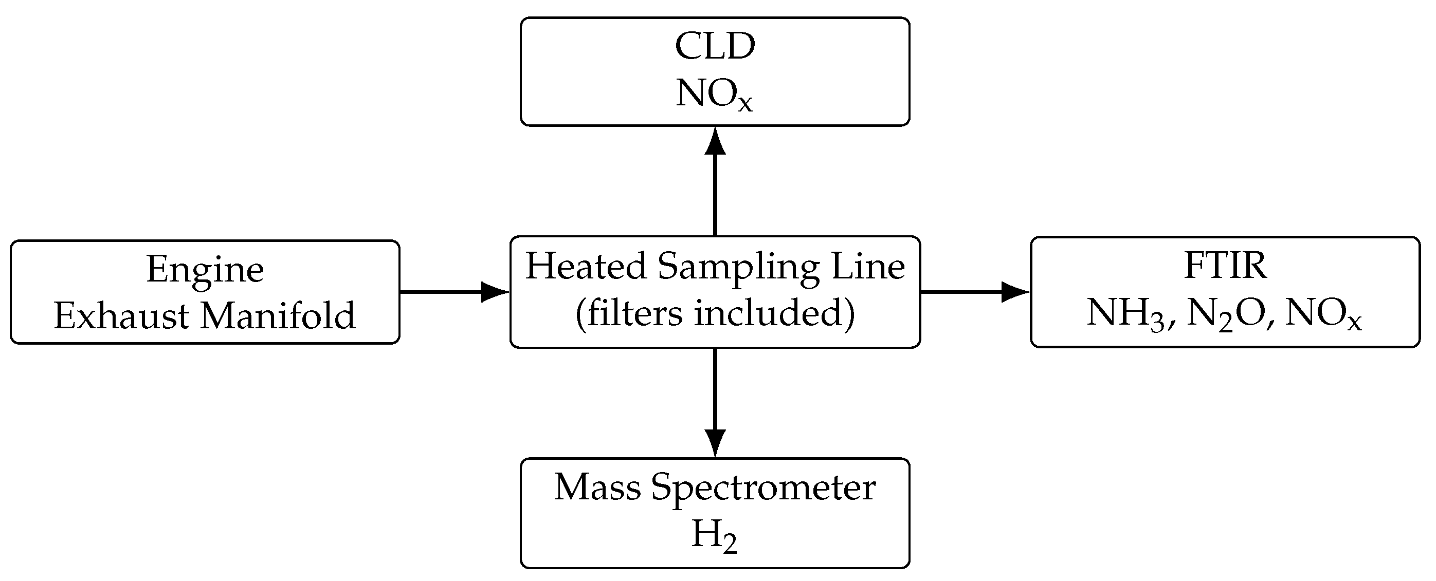
Exhaust gas emissions were monitored using complementary measurement systems to ensure reliable and accurate data. NOx concentrations were measured using a Chemiluminescence detector (CLD) (AVL, Graz, Austria) with a measurement uncertainty of 2% and a detection limit < 1 ppm. NH3 and N2O were measured using a Fourier Transform Infrared Spectroscopy (FTIR) (IAG Gas Analytics GmbH, Weikersdorf, Austria) with a detection limit of approximately 0.2–0.5 ppm and a measurement uncertainty of 3%. H2 concentrations were determined using a HSense (V&F Analyse- und Messtechnik GmbH, Absam, Austria) mass spectrometer with a detection limit below 1 ppm and an accuracy of 2% [22]. All sensors sampled exhaust gas directly from the exhaust manifold via heated stainless steel lines to prevent condensation and adsorption of reactive species. Sampling lines were equipped with filters to remove particulate matter, and the gas was kept at approximately engine exhaust temperature until entering the analyzers. Data acquisition was performed at a rate of 100 Hz, and measurements were averaged over 30 s to ensure reproducibility. Each analyzer was calibrated prior to testing using certified standard gases to guarantee accuracy. A schematic of the exhaust gas measurement setup is provided in Figure 3.

3. Ignition Characteristics of Pure NH3

NH3 presents significant challenges as a fuel due to its high auto-ignition temperature (924 K), low laminar flame speed, high evaporation enthalpy, and narrow flammability limits [9,18]. Often, H2 or other pilot fuels are used to aid inflammation. In this study, no additional fuels are used to support ignition, highlighting the critical importance of optimized ignition strategies for the initiation and stabilization of pure NH3 combustion. The effects of ignition timing, spark energy, and spark duration are evaluated to determine reliable ignition under different operating conditions.
Experiments are conducted to identify stable operation boundaries for pure NH3 combustion. Metrics such as COVIMEP of 3% must not be exceeded and standard deviation of the position of the center of gravity of the combustion (Mass Fraction Burnt (MFB)) MFB50) is used to quantify combustion stability. Sensitivity to the Air-Fuel-Ratio ( λ ), spark timing, and load is examined.
Mixture formation takes place by injecting liquid NH3 into the intake manifold, where it evaporates and mixes with the compressed intake air. No dedicated swirl or tumble generation devices are used; thus, mixing relies on turbulent diffusion in the intake manifold and cylinder. The influence of mixture quality, expressed by λ , was analyzed. Under lean conditions ( λ   >   1 ), the reduced reactivity of NH3 results in longer ignition delays and increased cycle-to-cycle variations, requiring extended spark durations for reliable flame kernel development. Regarding emissions, NOx concentrations initially increase under lean operation up to about λ = 1.3 due to higher oxygen availability, and only decrease beyond this point when combustion temperatures drop. In contrast, unburned NH3 emissions remain relatively constant across the investigated λ range, showing that incomplete conversion is less sensitive to the mixture quality than to the overall combustion temperature [20,23].

4. Results and Discussion

The experiments demonstrate that stable spark ignition of pure NH3 is feasible under controlled conditions. Compared to dual-fuel systems, the ignition delay is longer. However, the benefits of zero-carbon fuel without H2 or diesel addition support the potential for simplified NH3 engine concepts.

4.1. Combustion Stability and Burning Delay

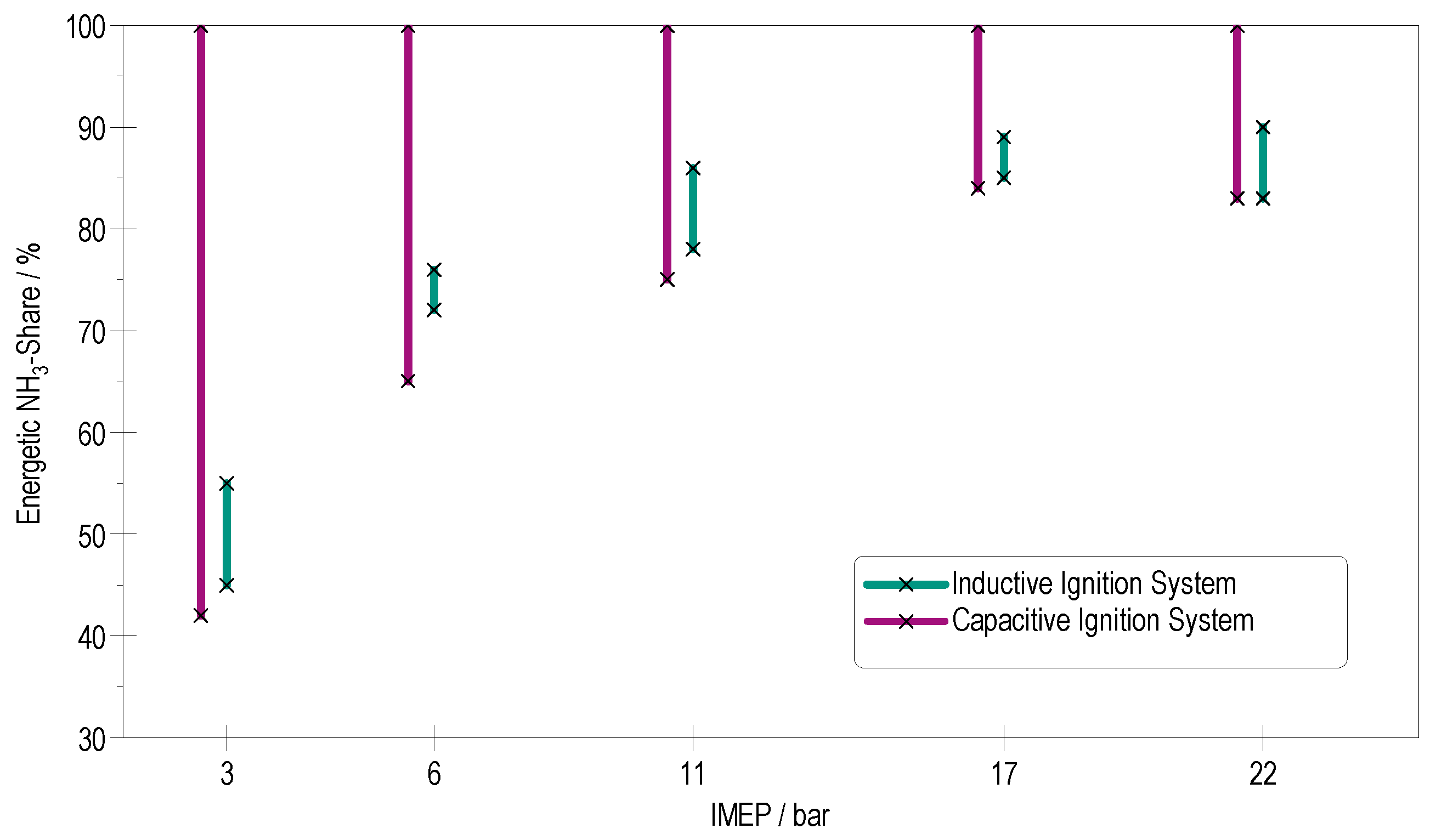
Figure 4 illustrates the limitations of different ignition systems by plotting the achievable Energetic Ammonia Share (EAS) versus the Indicated Mean Effective Pressure (IMEP). The maximum possible energetic H2 (thus minimal NH3) content which can be achieved without knocking or pre-ignition is shown. A target COVIMEP value below 3% is aimed for to ensure stable engine operation. The knocking factor (number of knocking cycles) was evaluated from 200 consecutive cycles using the knock criterion according to Mannesmann VDO DEWETRON (DEWETRON GmbH, Grambach, Austria). This refers to an industrial knock detection standard frequently used in engine test benches, based on knock intensity thresholds, as documented in KIT internal project reports and was required to remain below 5%. With an inductive ignition system (green line), a maximum EAS of 89% is achievable at full load (22 bar IMEP). However, at lower load operation, the maximum EAS is significantly reduced to 55%. For higher energetic NH3 shares at low load, combustion becomes unstable, defined by a coefficient of variation COVIMEP exceeding 3%. In contrast, the capacitive ignition system enables stable combustion with 100% EAS over the whole load range. Even at low loads, such as 3 bar IMEP (idle conditions), up to 100% EAS is achievable without additional H2. The operational window for pure NH3 is thus significantly extended compared to the inductive system [23].
Figure 5 shows the ignition timing, the °CA position for 10%, 50%, and 90% mass fraction burnt MFB (MFB10, MFB50, MFB90), as well as the energetic NH3 share plotted against the IMEP. For all operating points, except full load, the MFB50 is kept constant at 8 °CA aTDCf to maintain stable combustion phasing. At full load, however, the high compression ratio causes peak cylinder pressures to exceed 220 bar, requiring a delayed combustion phasing to avoid excessive mechanical stress. In the case of the inductive ignition system, H2 is required to stabilize inflammation and combustion. While at constant MFB50, the combustion using the capacitive ignition system reaches MFB10 earlier, whereas the inductive ignition system reaches the end of combustion (MFB90) faster. This shows that the combustion duration of pure NH3 is 2 °CA longer (see Figure 6, bottom left). This is due to the lower laminar flame speed of pure NH3.
There is a decreasing offset in the ignition angle between the ignition systems for the same MFB50 with load. This offset is presumably due to the share of H2 and the associated fast inflammation when using the inductive system. For higher loads and thus smaller shares of H2, the offset decreases. The burning delay (see Figure 6, top left) is defined as the time between ignition spark and MFB10. It is visible that the inflammation of pure NH3 is slower, despite the higher energy input of the capacitive ignition system. This demonstrates that the aforementioned properties of pure NH3 result in such challenging conditions for inflammation that a capacitive ignition system is required, and even then, the inflammation process is notably slower compared to H2. The indicated combustion efficiency (Figure 6) for both ignition systems is almost the same with around 50% at 22 bar Indicated Mean Effective Pressure (IMEP), with a small advantage for the inductive ignition system. The reason for this is the faster combustion due to the H2 share.

4.2. Heat Release

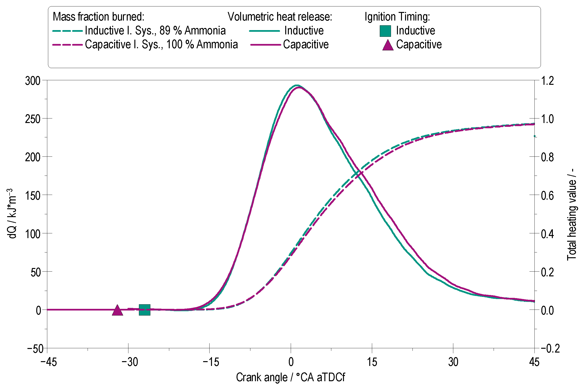
Figure 7 compares the total heating value and the volumetric heat release rate at 17 bar IMEP at maximum possible EAS for the two ignition systems. The total heating value and net heat release rate were derived from the measured in-cylinder pressure using the first law of thermodynamics, neglecting wall heat losses. Pressure data were acquired with a Kistler 6045BS3-2 sensor (Kistler Instruments AG, Winterthur, Switzerland) at 0.1 °CA. resolution and averaged over 200 consecutive cycles. A polytropic coefficient κ of 1.3 was assumed for compression and expansion. To reduce measurement noise, the data were smoothed using a Savitzky–Golay filter within a window of −30 to 90 °CA aTDCf. The net heat release rate was normalized to the maximum value and the cumulative heat release was calculated including the injected fuel mass and its lower heating value. The curves represent the mean values from measurement series with the lowest COVIMEP, in order to provide a consistent basis for evaluating combustion duration. The lowest COVIMEP value for the capacitive ignition system is 1.9% and the lowest value for the inductive ignition system is 2.0%. The results show that the combustion duration achieved with the capacitive ignition system is similar to that of the inductive ignition system, despite the fact that the latter requires an H2 admixture to initiate stable combustion. While the early combustion phase in the inductive system appears slightly faster (0.5 °CA) due to hydrogen’s higher reactivity, the overall heat release process closely aligns with that of the capacitive ignition system operating on 100% NH3. This shows that, under optimized ignition conditions, pure NH3 can achieve similar combustion characteristics without the need for carbon- or H2-based ignition assist.

4.3. Effect of Spark Energy and Duration

A particular advantage of the used capacitive ignition system is the ability to extend the spark duration over several degree Crank angle. The spark duration can be extended to 3000 µs, which means 27 °CA at 1500 rpm. This increases the likelihood that an ignitable mixture will pass between the electrodes and ignite, especially in the case of poor mixture formation or lean burning processes [24,25].

4.3.1. Low-Load Operation

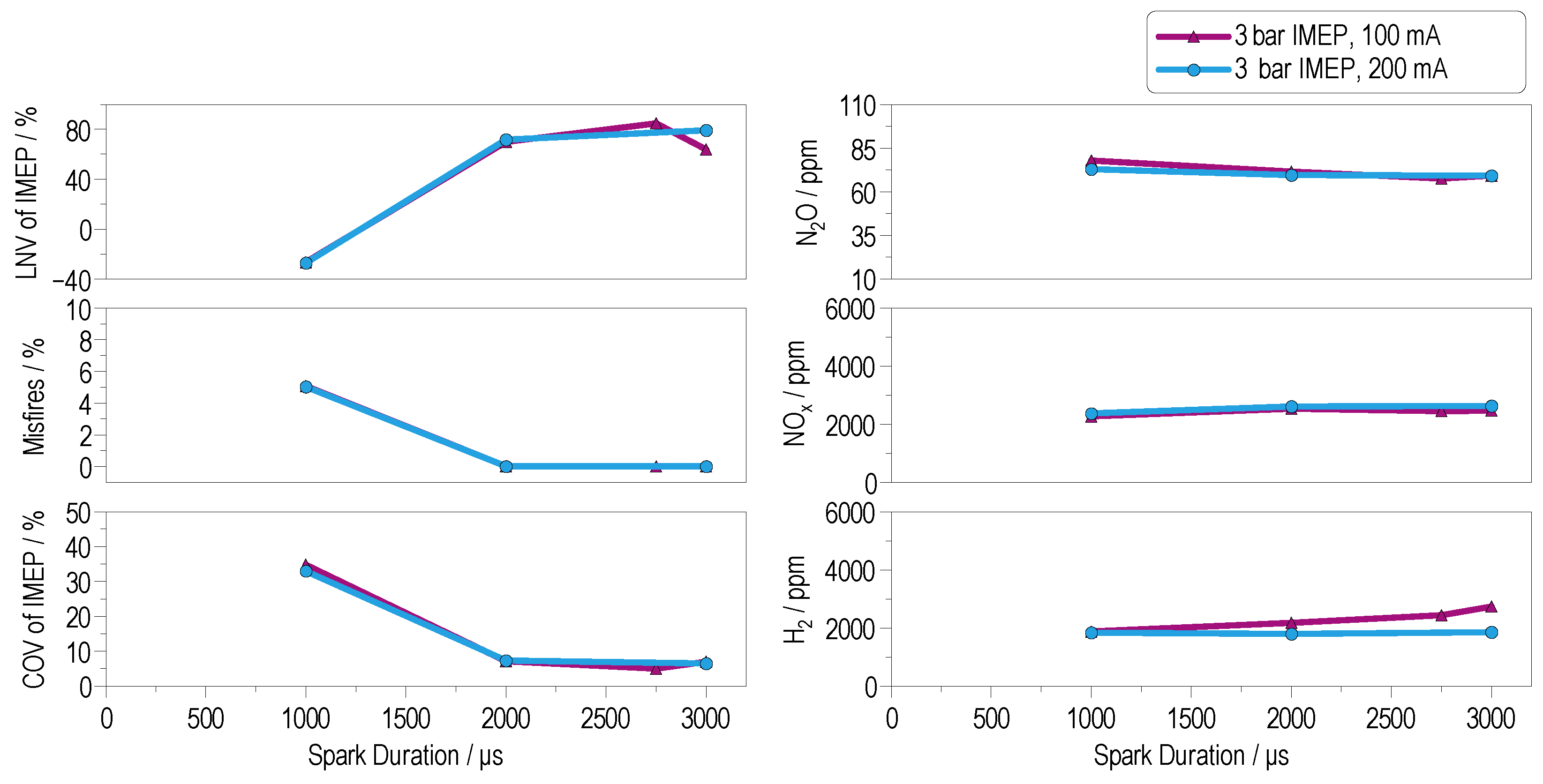
Engine operation at very low load points, such as 3 bar IMEP, presents significant challenges for pure NH3 combustion (see Figure 8). Under these conditions the in-cylinder temperatures and the rotational speeds are low. These factors severely limit the ignition and flame propagation of NH3 [26]. With the capacitive ignition system, it was possible to achieve stable engine operation. In order to better assess the increased COVIMEP, the percentage of misfires and the Lowest Nominal Value (LNV) of the IMEP were plotted. The LNVIMEP describes the difference between the lowest-measured IMEP value and the mean IMEP value. Its calculation is shown in Equation (1).
L N V IMEP ( % ) = 100 I M E P Min . I M E P Ave . ;
Appropriate values are typically above 75%, indicating proper ignition and combustion of the air–fuel mixture. Negative values indicate unstable combustion or misfiring [27]. With a spark duration longer than 2000 µs, a stable combustion without misfires can be achieved. A shorter spark duration increases the likelihood of misfiring.
From an emissions perspective, NH3 slip was found to be beyond the upper detection limit of the FTIR measurement system (5000 ppm), indicating significant amounts of unburned fuel. This is attributed to incomplete combustion due to poor ignition conditions and weak flame development. At the same time, nitrous oxide (N2O) concentrations reached notably high levels of approximately 80 ppm. The elevated N2O concentrations observed under low-load conditions can be explained by the underlying reaction pathways of NH3 oxidation. At reduced in-cylinder temperatures, thermal NO formation via the Zeldovich mechanism is suppressed, while intermediate species such as NH, NH2, and HNO become more stable. In particular, N2O is formed through reactions such as
NH + NO N 2 O + H
N H 2 + O HNO + H
These reactions are followed by subsequent HNO conversion to N2O. As a result, the relative contribution of these low-temperature pathways increases under part-load operation, leading to higher measured N2O emissions despite the generally lower thermal load [8,11]. These findings are consistent with combustion studies, which report that at reduced combustion temperatures and lower conversion rates, the formation of N2O from fuel-bound nitrogen species is significantly enhanced [12].

4.3.2. Partial-Load Operation

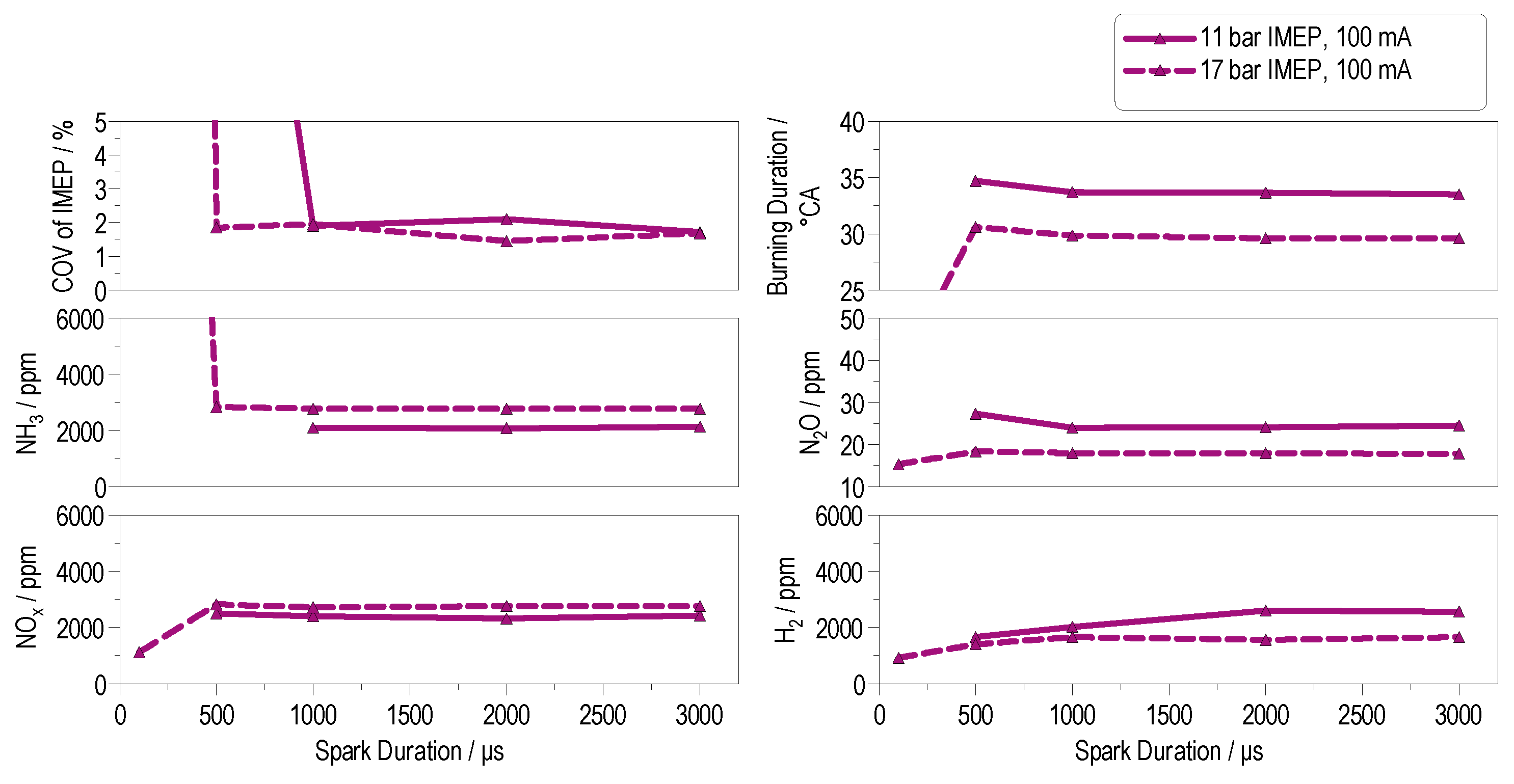
Compared to idle operation, combustion stability significantly improves at 11 bar IMEP. At 17 bar IMEP, the required spark duration can be further reduced by 50% compared to 11 bar IMEP without compromising ignition reliability or combustion quality. This can be seen in Figure 9. In general, the higher the load, the shorter the minimum spark duration required for stable combustion. This trend is attributed to the elevated in-cylinder temperatures at higher loads, which enhance the ignitability of the mixture and promote more robust flame kernel development. In addition to the thermal effect, the higher temperature and pressure levels accelerate the reaction kinetics of the NH3/H2 oxidation mechanism and increase the concentration of reactive radicals such as H, O, and OH. These radicals play a key role in chain-branching reactions, thereby facilitating earlier ignition and more stable flame propagation [8,11]. As a result, not only the ignition process but also the overall burn duration is reduced, contributing to a more rapid and efficient energy release. The NH3 and NOx emissions are present in a ratio of 1:1 in a region of 2000 ppm. This ratio is very attractive for a complete passive SCR system. In summary, it can be said that the spark duration has a greater influence on combustion stability than the spark current.

4.3.3. High-Load Operation

At high load (22 bar IMEP, see Figure 10), it was possible to significantly reduce the spark duration by 96% compared to 11 bar IMEP without compromising inflammation reliability. In general, the results show that the required spark energy for successful inflammation of NH3 decreases with increasing engine load. Under high-load conditions, the engine exhibits excellent combustion stability even at significantly reduced spark durations. Notably, a spark duration as short as 40 µs proves sufficient to ensure reliable ignition of the mixture. The MFB50 must be selected late (13 °CA aTDCf) at 22 bar IMEP to avoid exceeding the peak pressure. This causes a higher COVIMEP. At high-load operation, NH3 emissions remained at around 3000 ppm, NOx emissions at about 2000 ppm, and N2O concentrations stabilized near 20 ppm. These findings highlight the importance of optimizing spark duration according to load conditions, in order to balance ignition stability, emissions performance, and spark plug wear.

5. Conclusions and Outlook

Summary of Key Findings

Ignition and combustion stability: The experiments demonstrate that stable operation of a combustion engine with 100% NH3 is feasible across the entire load range using a capacitive ignition system. The findings highlight that increasing engine load enables both shorter spark durations and reduced burn durations, due to not only elevated in-cylinder temperatures but also to enhanced radical pool formation and faster kinetic reactions in the NH3/H2 oxidation mechanism [28]. These effects improve the ignitability of the mixture and ultimately enhance combustion stability and efficiency. At low loads (3 bar IMEP), the system requires long spark duration (≥2000 µs) to ensure reliable ignition, whereas at high loads, short spark duration (40 µs) suffices. This indicates that the thermal decomposition of NH3 into H2 is feasible under high-pressure and high-temperature conditions, facilitating inflammation due to the presence of H2. With the used high compression ratio, the end-of-compression temperature reaches approximately 1066 K, providing favorable conditions for the decomposition of NH3, which is reported to occur above 700 K [29,30].
Emissions Low loads and low temperatures lead to slow flame propagation and thus incomplete combustion, high NH3 slip (>5000 ppm) and elevated N2O emissions (≈80 ppm). At low loads, elevated N2O emissions are observed, which can be attributed to the preferential formation of N2O over NOx under low-temperature combustion conditions [17]. At higher loads (11–22 bar IMEP), combustion of pure NH3 is very stable with the capacitive ignition system. The NH3 slip drops (≈3000 ppm), NOx emissions (≈3000 ppm) remain moderate, and the level of N2O emissions (≈20 ppm) decreases as the higher temperatures promote more complete oxidation.
Feasibility: Pure NH3 can be operated in a spark-ignited engine without H2 or carbon-based pilot fuels when the ignition systems and strategies are optimized. The capacitive ignition system provided stable and efficient combustion over the whole load range.
Limitations and outlook: However, this study is subject to certain limitations. First, the experiments were carried out under steady-state single-cylinder conditions, which may not fully capture transient operation or multi-cylinder effects. In addition, the analysis focused primarily on combustion and gaseous emissions and therefore, particulate formation, long-term ignition system durability, and material compatibility with NH3 were beyond the scope of this work. Future work should therefore investigate transient operation strategies, including cold start behavior and load transitions, as well as durability aspects of ignition components under extended high-load operation. Furthermore, the integration of exhaust aftertreatment systems for simultaneous reduction of unburned NH3, NOX, and N2O will be essential to evaluate the overall viability of NH3 as a carbon-free engine fuel.

Author Contributions

Conceptualization, A.B., M.G., D.B., and T.C.; methodology, A.B., M.G; validation, A.B. and M.G.; formal analysis, A.B. and M.G.; investigation, A.B.; resources, T.K.; data curation, A.B.; writing—original draft preparation, A.B. and M.G.; writing—review and editing, T.C., D.B., O.T., and J.Ä.; visualization, A.B.; supervision, O.T.; project administration, A.B.; funding acquisition, A.B. All authors have read and agreed to the published version of the manuscript.

Funding

This research was funded by the Federal Ministry of Education and Research (BMBF, Germany), grant number 03HY2090, as part of the CAMPFIRE project.

Data Availability Statement

The original contributions presented in this study are included in the article. Further inquiries can be directed to the corresponding author.

Acknowledgments

This work was carried out within the CAMPFIRE project of the H2 Flagship Project TransHyDE and was funded by the German Federal Ministry for Education and Research. We gratefully acknowledge Liebherr for supplying the single-cylinder engine and supporting this research. We also acknowledge the support of the KIT-Publication Fund of the Karlsruhe Institute of Technology for covering the Open Access fees.

Conflicts of Interest

Daniel Bäck, Tomas Carlsson and Jakob Ängeby were employed by the company SEM AB. The remaining authors declare that the research was conducted in the absence of any commercial or financial relationships that could be construed as a potential conflict of interest.

Abbreviations

λAir–Fuel Ratio
AFRAir–Fuel Ratio
CACrank angle
CAaTDCfCrank angle after Top Dead Center firing
CAbTDCfCrank angle before Top Dead Center firing
CLDChemiluminescence detector
CO2Carbon dioxide
COVCoefficient of Variation
EASEnergetic Ammonia Share
EGRExhaust Gas Recirculation
FTIRFourier Transform Infrared Spectroscopy
GHGGreenhouse Gas
H2Hydrogen
IMEPIndicated Mean Effective Pressure
IMOInternational Maritime Organization
LNVLowest Nominal Value
MFBMass Fraction Burnt
N2ONitrous oxide
NH3Ammonia
NOxNitrogen oxides
SISpark Ignition
TDCTop Dead Center

References

  1. International Maritime Organization (IMO). International Maritime Organization (IMO) Adopts Revised Strategy to Reduce Greenhouse Gas Emissions from International Shipping. Available online: https://www.imo.org/en/MediaCentre/PressBriefings/pages/Revised-GHG-strategy.aspx (accessed on 19 September 2025).
  2. Mei, B.; Zhang, J.; Shi, X.; Xi, Z.; Li, Y. Enhancement of ammonia combustion with partial fuel cracking strategy: Laminar flame propagation and kinetic modeling investigation of NH3/H2/N2/air mixtures up to 10 atm. Combust. Flame 2021, 231, 111472. [Google Scholar] [CrossRef]
  3. Valera-Medina, A.; Xiao, H.; Owen-Jones, M.; David, W.; Bowen, P.J. Ammonia for power. Prog. Energy Combust. Sci. 2018, 69, 63–102. [Google Scholar] [CrossRef]
  4. Reiter, A.J.; Kong, S.C. Demonstration of compression-ignition engine combustion using ammoniain reducing greenhouse gas emissions. Energy Fuels 2008, 22, 1234–1242. [Google Scholar] [CrossRef]
  5. Di Matteo, A.; Bracho, G.; Pinilla, D.; Somers, L.M.T. Numerical investigation of direct ammonia injection and combustion. Fuel 2025, 398, 135485. [Google Scholar] [CrossRef]
  6. Hayakawa, A.; Arakawa, Y.; Mimoto, R.; Somarathne, K.D.K.A.; Kudo, T.; Kobayashi, H. Experimental investigation of stabilization and emission characteristics of ammonia/air premixed flames in a swirl combustor. Int. J. Hydrogen Energy 2017, 42, 14010–14018. [Google Scholar] [CrossRef]
  7. Lhuillier, C.; Brequigny, P.; Contino, F.; Mounaïm-Rousselle, C. Combustion Characteristics of Ammonia in a Modern Spark-Ignition Engine; SAE Technical Paper 2019-24-0237; SAE International: Warrendale, PA, USA, 2019. [Google Scholar] [CrossRef]
  8. Glarborg, P.; Miller, J.A.; Ruscic, B.; Klippenstein, S.J. Modeling nitrogen chemistry in combustion. Prog. Energy Combust. Sci. 2018, 67, 31–68. [Google Scholar] [CrossRef]
  9. Zander, M.; Thomas, W. Some thermodynamic properties of liquid ammonia: PVT data, vapor pressure, and critical temperature. J. Chem. Eng. Data 1979, 24, 1–2. [Google Scholar] [CrossRef]
  10. Hayakawa, A.; Goto, T.; Mimoto, R.; Arakawa, Y.; Kudo, T.; Kobayashi, H. Laminar burning velocity and Markstein length of ammonia/air premixed flames at various pressures. Fuel 2015, 159, 98–106. [Google Scholar] [CrossRef]
  11. Miller, J.A.; Melius, C.F.; Glarborg, P. The CH3+NO rate coefficient at high temperatures: Theoretical analysis and comparison with experiment. Int. J. Chem. Kinet. 1998, 30, 223–232. [Google Scholar] [CrossRef]
  12. Naruse, I.; Yamamoto, Y.; Itoh, Y.; Ohtake, K. Fundamental study on N2O formation/decomposition characteristics by means of low-temperature pulverized coal combustion. Symp. (Int.) Combust. 1996, 26, 3213–3221. [Google Scholar] [CrossRef]
  13. Lhuillier, C.; Brequigny, P.; Contino, F.; Mounaïm-Rousselle, C. Experimental study on ammonia/hydrogen/air combustion in spark ignition engine conditions. Fuel 2020, 276, 118–126. [Google Scholar] [CrossRef]
  14. Park, C.; Jang, Y.; Min, C.; Kim, Y.; Choi, Y. Experimental investigation of operating conditions on ammonia combustion in a direct-injection engine with hydrogen addition. Renew. Sustain. Energy Rev. 2024, 171, 113229. [Google Scholar] [CrossRef]
  15. Herwig, H. Wärmeübertragung A-Z: Systematische und Ausführliche Erläuterungen Wichtiger Größen und Konzepte; VDI-Buch; Springer: Berlin/Heidelberg, Germany, 2000. [Google Scholar] [CrossRef]
  16. Čaika, V.; Dörr, N. Thermal and Transport Properties of Diesel Fuel and Their Effect on Injection Modelling; Consiglio Nazionale delle Ricerche: Rome, Italy, 2005. [Google Scholar] [CrossRef]
  17. Park, C.; Choi, Y.; Park, G.; Jang, I.; Kim, M.; Kim, Y.; Choi, Y. Investigation on the reduction in unburned ammonia and nitrogen oxide emissions from ammonia direct injection SI engine by using SCR after-treatment system. Heliyon 2024, 10, e37684. [Google Scholar] [CrossRef] [PubMed]
  18. Essmann, S.; Dymke, J.; Höltkemeier-Horstmann, J.; Möckel, D.; Schierding, C.; Hilbert, M.; Yu, C.; Maas, U.; Markus, D. Ignition characteristics of hydrogen-enriched ammonia/air mixtures. Appl. Energy Combust. Sci. 2024, 17, 100254. [Google Scholar] [CrossRef]
  19. Braun, A.; Baufeld, T.; Bernhardt, S.; Kubach, H.; Mohr, H.; Prehn, S. Combustion concept for ammonia-fuelled cracker-engine-unit as propulsion system for inland waterway vessels. In Proceedings of the 8th Rostock Large Engine Symposium, Rostock, Germany, 12–13 September 2024. [Google Scholar] [CrossRef]
  20. Braun, A.; Kubach, H.; Braun, S.; Reinbold, M.; Bernhardt, S.; Gierenz, N.; Buchholz, B.; Engelmeier, L.; Fehlemann, L.; Steffen, M.; et al. Entwicklung einer Ammoniak-betriebenen Cracker- Motor-Einheit als Antriebssystem für Binnenschiffe. In Proceedings of the Dessau Gas Engine Conference, Dessau, Germany, 15–16 May 2024. [Google Scholar] [CrossRef]
  21. Ängeby, J.; Gustafsson, B.; Johnsson, A. Zündsteuerungsmodul für Wasserstoffverbrennungsmotoren. Mtz—Mot. Z. 2023, 84, 48–53. [Google Scholar] [CrossRef]
  22. V&F Analyse- und Messtechnik GmbH. Produktflyer V&F HSense: Prozess-Massenspektrometer HSense; V&F Analyse- und Messtechnik GmbH: Absam, Österreich, 2024. [Google Scholar]
  23. Braun, A.; Baufeld, T.; Engelmeier, L.; Gierenz, N.; Kubach, H.; Mohr, H.; Prehn, S.; Silvestrini, S. Development of an ammonia-fueled cracker-engine-unit as propulsion system for inland waterway vessel. In Proceedings of the CIMAC Conference, Zurich, Switzerland, 19–22 May 2025. [Google Scholar] [CrossRef]
  24. Nakai, M.; Nakagawa, Y.; Hamai, K.; Sone, M. Stabilized Combustion in a Spark Ignited Engine through a Long Spark Duration; SAE International: Warrendale, PA, USA, 1985. [Google Scholar] [CrossRef]
  25. Sandhu, N.S.; Zhu, H.; Leblanc, S.; Yu, X.; Yang, H.; Ting, D.; Zheng, M. Effect of Spark Discharge Duration and Timing on the Combustion Initiation in a Lean Burn SI Engine; SAE International: Warrendale, PA, USA, 2021. [Google Scholar] [CrossRef]
  26. Yin, X.; Sun, N.; Sun, T.; Shen, H.; Mehra, R.K.; Liu, J.; Wang, Y.; Yang, B.; Zeng, K. Experimental investigation the effects of spark discharge characteristics on the heavy-duty spark Ignition natural gas engine at low load condition. Energy 2022, 239, 122244. [Google Scholar] [CrossRef]
  27. Han, S.B. Cycle-to-cycle variations under cylinder-pressure-based combustion analysis in spark ignition engines: Department of Mechanical Engineering, Induk Institute of Technology. KSME Int. J. 2000, 14, 1151–1158. [Google Scholar] [CrossRef]
  28. Stagni, A.; Arunthanayothin, S.; Dehue, M.; Herbinet, O.; Battin-Leclerc, F.; Brequigny, P.; Mounaim-Rousselle, C.; Favarelli, T. Low- and intermediate-temperature ammonia/hydrogen oxidation in a flow reactor: Experiments and wide-range kinetic modeling. Chem. Eng. J. 2023, 481, 144577. [Google Scholar] [CrossRef]
  29. Liu, W.; Qi, Y.; Zhang, R.; Zhang, Q.; Wang, Z. Hydrogen production from ammonia-rich combustion for fuel reforming under high temperature and high pressure conditions. Fuel 2022, 327, 124830. [Google Scholar] [CrossRef]
  30. Linde Gas GmbH. Data Sheet Ammonia: Ammonia, Anhydrous: Version 2.0. Linde Gas GmbH: Pullach, Germany, 2013. Available online: https://produkte.linde-gas.at/sdb_konform/NH3_10021772EN.pdf (accessed on 19 September 2025).
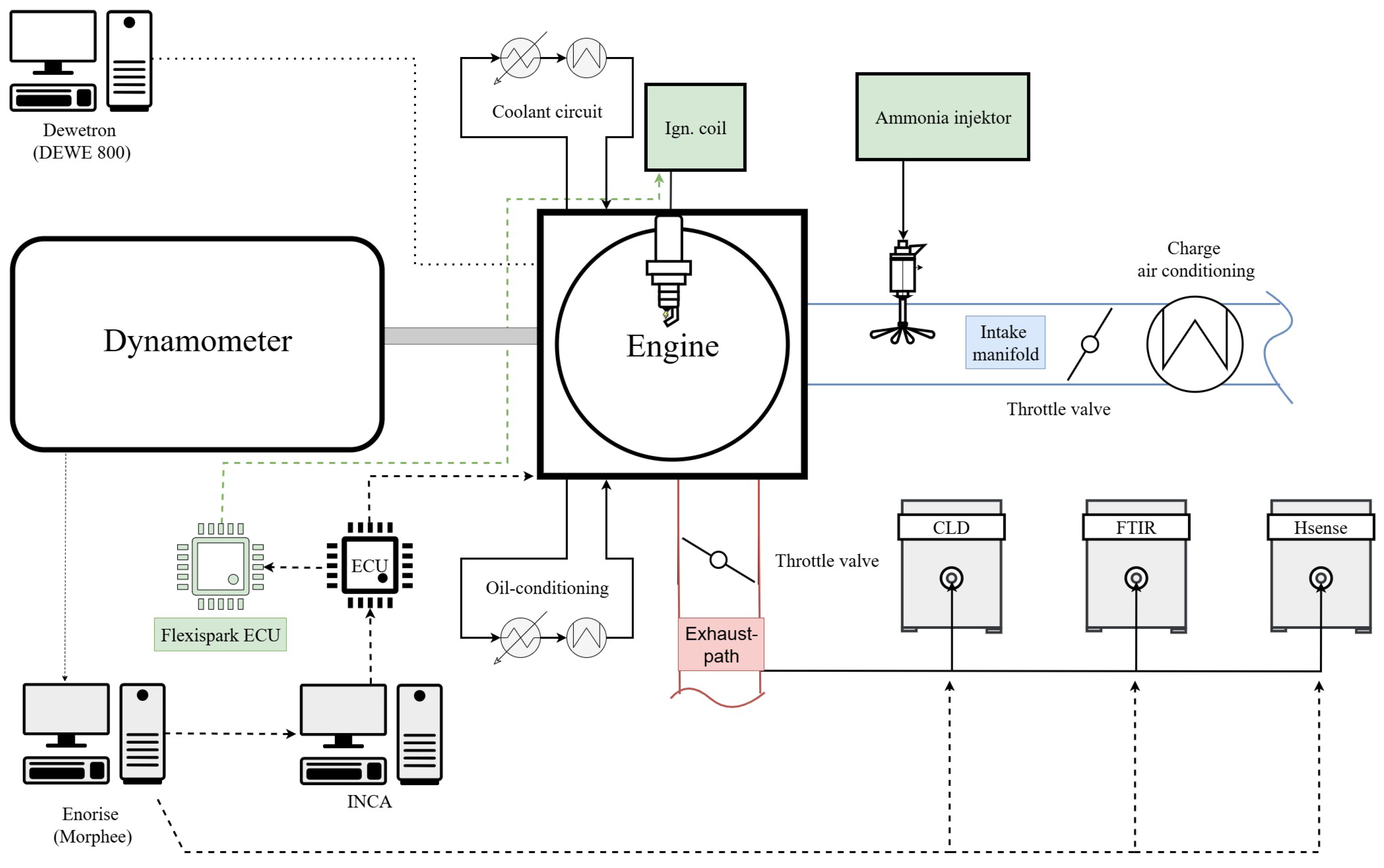
Figure 1. Schematic overview of the test bench setup. Dashed lines indicate electrical connections for signal transmission, while solid lines represent physical conduits.
Energies 18 05051 g001
Figure 2. Schematic of the FlexiSpark capacitive ignition system (ICM–Ignition Coil–Spark Plug).
Energies 18 05051 g002
Figure 3. Schematic of the exhaust gas measurement setup.
Energies 18 05051 g003
Figure 4. Restriction of the different ignition concepts. The maximum possible EAS versus the IMEP is shown for the inductive ignition system and the capacitive ignition system.
Energies 18 05051 g004
Figure 5. Energetic NH3 share, MFB10, MFB50, MFB90, and ignition timing for different load points depending on the ignition concepts.
Energies 18 05051 g005
Figure 6. Burning delay, burning duration and indicated efficiency over the IMEP for the capacitive ignition system with 100% NH3 and the inductive ignition system at the maximum possible energetic NH3 share with a COVIMEP    3 % .
Energies 18 05051 g006
Figure 7. Total heating value, net heat release rate, and ignition timing over Crank angle for different ignition concepts at 17 bar IMEP and Lambda 1.
Energies 18 05051 g007
Figure 8. Emissions and COVIMEP for idle speed 3 bar IMEP versus spark duration.
Energies 18 05051 g008
Figure 9. Emissions and COVIMEP over spark duration for 11 bar IMEP and 17 barIMEP for 100% NH3 combustion.
Energies 18 05051 g009
Figure 10. Emissions and COVIMEP versus spark duration for 22 bar IMEP (ignition timing = 22 °CAbTDCf).
Energies 18 05051 g010
Table 1. Comparison of selected physical and chemical properties of NH3 and reference fuels [15,16,17,18].
PropertyUnitNH3H2Diesel FuelCH4 (LNG)
Volumetric Calorific ValueMJ/L
at bar
12.68
9
2.85
350
35.15
1
9.07
250
Max. Laminar Flame Speedm/s0.072.910.40.37
Adiabatic Flame TemperatureK2073238323032273
Auto-ignition TemperatureK924833>498743
Ignition Energy (1 bar and 298 K)mJ18 a0.0210–300.28
Evaporation EnergykJ/kg1368223200–300511
Tank Volume (rel. to diesel)-2.84.21.01.3
a Ref. [18] provides a literature overview of measured values. The majority of the values are in the range 8–18 mJ.
Table 2. Technical specifications of the single-cylinder test engine.
Engine DetailSpecification
Stroke157 mm
Bore135 mm
Max. Speed1900 rpm
Operation Principle4-stroke spark ignition (SI)
Displacement2.24 L
Engine TypeModified Liebherr diesel-fuel engine
Table 3. Technical specifications of the ignition system.
Ignition System DetailSpecification
Spark CurrentAdjustable in the range of 50–300 mA
Spark DurationAdjustable in the range of 40–3000 µs
Available Voltage>40 kV for initial breakdown
Spark EnergyConfigurable from 5 mJ up to 330 mJ
Disclaimer/Publisher’s Note: The statements, opinions and data contained in all publications are solely those of the individual author(s) and contributor(s) and not of MDPI and/or the editor(s). MDPI and/or the editor(s) disclaim responsibility for any injury to people or property resulting from any ideas, methods, instructions or products referred to in the content.