Article

Heat Transfer Characteristics of Multi-Inlet Rotating Disk Cavity

Department of Energy and Power Engineering, Tsinghua University, Beijing 100084, China
*
Author to whom correspondence should be addressed.
Energies 2025, 18(19), 5049; https://doi.org/10.3390/en18195049
Submission received: 18 July 2025 / Revised: 13 September 2025 / Accepted: 17 September 2025 / Published: 23 September 2025
(This article belongs to the Section J1: Heat and Mass Transfer)

Abstract

The secondary air system plays important roles in gas turbines, such as cooling hot-end components, sealing the rim, and balancing axial forces. In this paper, the flow structure and the heat transfer characteristics of the rotating disk cavity with two inlets and single outlet is studied by CFD (Computational Fluid Dynamics) approach. The effect and mechanism under higher rotational speed and larger mass flow rate are also discussed. The results show that a large-scale vortex is induced by the central inlet jet in the low-radius region of the cavity, while the flow structure in the high-radius region is significantly influenced by rotational speed and flow rate. Increasing the rotational speed generally enhances heat transfer because it amplifies the differential rotational linear velocity between the disk surface and nearby wall flow, consequently thinning the boundary layer. Increasing the mass flow rate enhances heat transfer through two primary mechanisms: firstly, it elevates the turbulence intensity of the near-wall fluid; secondly, the higher radial velocity results in a thinner boundary layer.

1. Introduction

The secondary air system of gas turbines is an independent system separate from the main flow components. It connects the compressor and the turbine through a network of flow paths in series and parallel configurations with diverse functions. Typically, air is extracted from designated stages of the compressor and directed through various structural elements (such as holes, pipes, sealing rings, and specially designed cavities) located either internally or externally to the main flow path. This air follows predetermined flow routes and meets specific parameter requirements (pressure, temperature, and flow rate) to fulfill functions such as disk cooling and gap sealing. Finally, the air is discharged from designated sections of the main flow path, where it either merges with the primary flow or leaks directly outside the engine. The secondary air system plays important roles in gas turbines, such as cooling hot-end components, sealing the rim, and balancing axial forces. With the continuous improvement of gas turbine operating parameters, the optimization design of the secondary air system to reduce the demand for cooling air, thereby increasing the output power and efficiency of gas turbines, has gradually become an important research area. The rotating disk cavity is an important part of the secondary air system, with a complex and various structure. The study of its internal flow pattern and heat transfer characteristics is of great importance.
Research on cavity flow can be traced back to Von Karman’s study [1] in 1921 on the flow characteristics around a rotating disk in an infinite stationary space (free disk), which have laid the theoretical foundation for subsequent investigations of flow patterns inside rotating disk cavities. The fluid near the rotating disk forms a radial outflow due to centrifugal forces induced by rotation. According to the continuity principle of fluid dynamics, this outward flow is compensated by an axial inflow toward the disk surface. When a stationary disk is positioned parallel to the rotating disk, part of the fluid from the stationary disk side flows toward the rotating disk side, resulting in an axial outflow. Similarly, based on the fluid continuity assumption, a radial inflow emerges near the stationary disk surface. Scholars primarily investigated the internal flow pattern and heat transfer characteristics of the rotating disk cavity through experiments. In 1992, Farthing et al. [2] found that the flow in the rotating disk cavity can be divided into a “radial arm,” a “forward zone,” a “rearward zone,” and a “dead zone” using flow visualization and LDA measurements. In 2000, Alexiou et al. [3] revealed that in the rotationally dominated regime, the heat transfer occurs through a process of free convection, where the buoyancy force is induced by rotation. In 2005, Tian Shuqing et al. [4] found that centrifugal buoyancy force is the primary factor causing flow instability. In 2006, Bohn et al. [5] found that the flow pattern changes between a single pair, double pairs, and triple pairs of vortices with a certain periodicity. Scholars have studied the flow pattern and the distribution characteristics of some heat transfer parameters by experiment, but the characteristics under different conditions are mainly studied by the CFD approach. In 2008, Tian Shuqing et al. [6] carried out simulation for a heated rotating cavity with an axial throughflow and found that an increase in axial Reynolds number and a decrease in Grashof number increase the number of circulation couples in the cavity. In 2018, through thermal–fluid–solid coupling analysis, Quan Jian et al. [7] found that an increase in cooling air mass flow rate will significantly strengthen the heat exchange of both disks and a reduction in disk gap will only strengthen the heat exchange of the upstream disk. In 2022, Jackson et al. [8] acquired distributions of disk temperature and heat flux in a closed cavity. In general, scholars have developed effective experimental techniques and simulation methods for the study of rotating disk cavities.
However, these studies have mainly focused on simple disk cavities with a single inlet and single outlet, with less research on disk cavities with multi-inlet and multi-outlet structures. In 2003, Bai Luolin et al. [9] conducted simulation on a rotating disk cavity with a single inlet and three outlets and found that vortex numbers and ranges are mainly controlled by the turbulence parameter. In 2018, Guo Jun et al. [10] investigated the variation of the heat transfer characteristics of the disk surface with the rotational Reynolds number. In 2021, Wu Zeyu et al. [11] obtained the factors influencing the adiabatic wall temperature of a disk cavity with two inlets and a single outlet through simulation. In 2023, Li Zheng et al. [12] explored the influence of multiple incoming streams on the disk’s heat transfer performance. Previous studies lack a systematic analysis of the heat transfer characteristics of the rotating disk cavity with a complex structure and its influencing factors.
In this paper, the flow structure and the heat transfer characteristics of the rotating disk cavity with two inlets and a single outlet are studied by CFD approach. The effect and mechanism of enhanced heat transfer on the disk surface under higher rotational speed and larger mass flow rate have also been discussed.

2. Model and Numerical Methods

2.1. Model of the Multi-Inlet Cavity

By simplifying the rotating disk cavity structure in the real gas turbine, a rotating disk cavity model with a central inlet, an inlet at high radius, and a radial outlet is established, as shown in Figure 1. The upstream and downstream disks rotate in the same direction with the same rotational speed. The geometric parameters of the model are shown in Table 1.

2.2. Mesh and Boundary Conditions of the Model

A full-annulus model was first constructed to verify circumferential uniformity. Both temperature and streamline distributions within the cavity demonstrate excellent circumferential uniformity, as illustrated in Figure 2. Based on that, a 30-degree sector model was developed for numerical simulation to conserve computational resources. We adopted a pressure-based segregated algorithm, specifically the SIMPLE scheme, to solve the governing equations and to accurately capture the steep pressure gradients induced by the high-speed rotation.
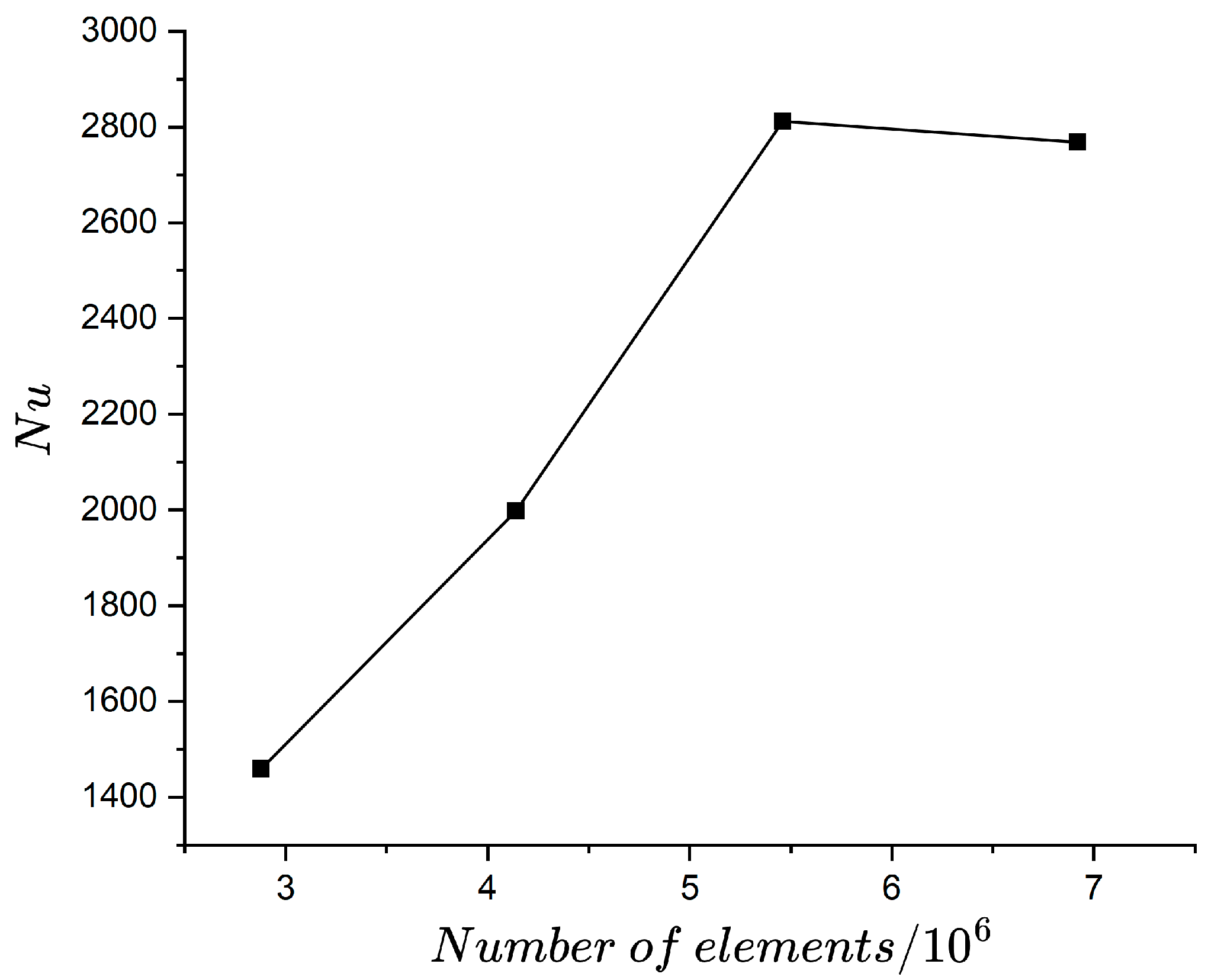
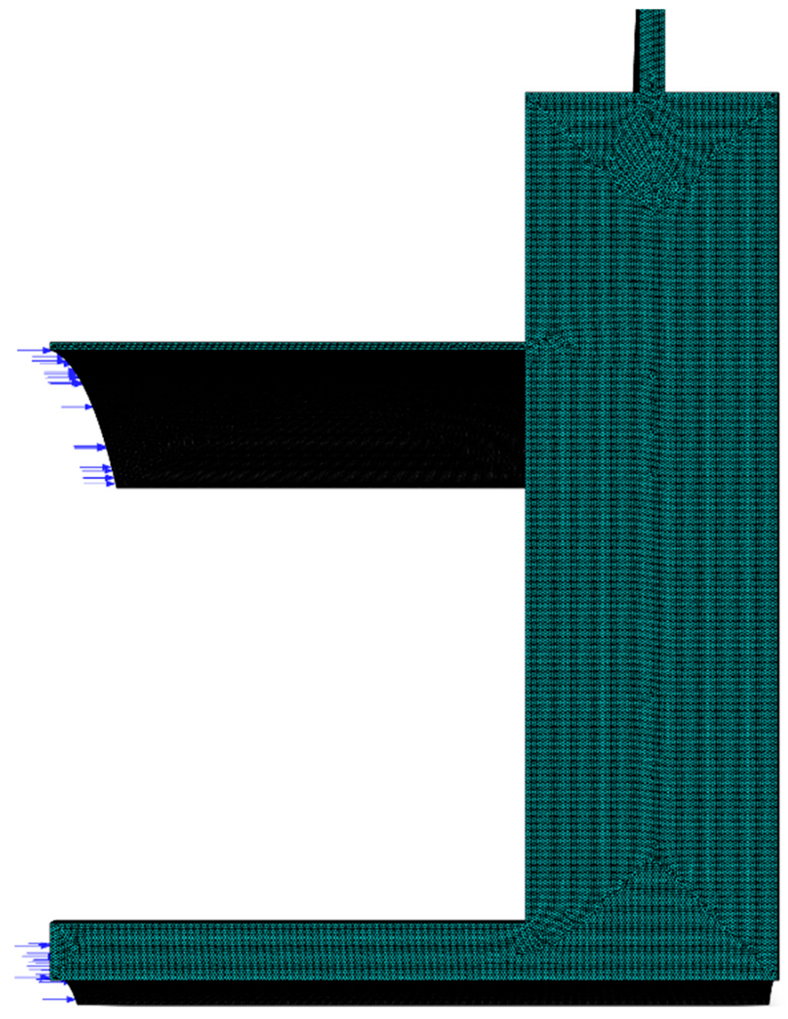
We performed the simulation using different grid densities and monitored the Nusselt number at r/b = 0.5 to verify grid independence, with the results shown in Figure 3. The grids are prepared by reducing the maximum face size and maximum cell length simultaneously. The final validated mesh for numerical simulation contains approximately 5.46 million elements after grid independence verification, as shown in Figure 4. The sector model is discretized with a hexahedral mesh, featuring a minimum element size of 0.005 mm and a growth rate of 1.2. The prism layer mesh consists of 10 layers, with a first-layer height of 0.003 mm to achieve a y+ value of approximately 1.
The mass flow rate is specified in the central inlet and the inlet at high radius. The total temperature is set at 298 K in the central inlet and 348 K in the inlet at high radius. The pressure in the outlet is set at one standard atmosphere pressure. In the numerical simulation of this paper, the gas is set as ideal gas to simplify the numerical simulation and reduce the computation time. Since the simulation is conducted essentially under normal temperature and pressure, real gas effects would not impact the simulation results. The downstream disk is set as an adiabatic wall or a wall with constant heat flux in different cases. The constant heat flux boundary condition is adopted based on the following considerations. Firstly, it serves as a reasonable approximation of practical scenarios in gas turbine secondary air system, where rotating components may be subjected to relatively stable thermal radiation or conduction from adjacent high-temperature regions. Secondly, the constant heat flux condition contributed to stable convergence behavior in the simulation. Both side surfaces are set as periodic boundary conditions. All other walls are set as adiabatic wall.

2.3. Numerical Methods and Validation

This study employs the commercial CFD software ANSYS Fluent 2022 for simulation, conducting a three-dimensional steady-state solution. The rotation reference system is used with a given rotation speed. The working fluid is air, modeled as an ideal gas, with its density calculated by the ideal gas law. All walls are set as no-slip wall and are stationary relative to the rotation reference system. The turbulence model selected is the Realizable k-ε model, with Enhanced Wall Treatment applied in the near-wall region. Viscous dissipation is employed to consider the influence of frictional heat.
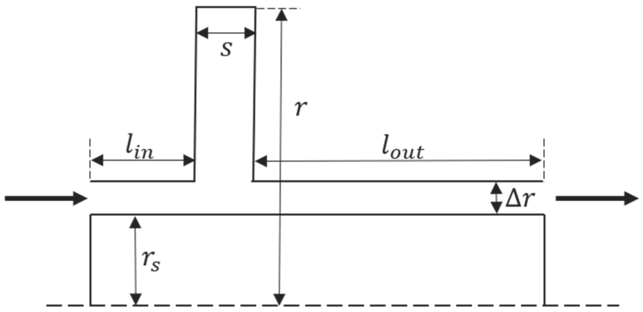
Due to the lack of widely recognized experimental heat transfer data for the rotating disk cavity with two inlets and one outlet in the current research, we have to employ the experimental heat transfer data from a single-inlet, single-outlet rotating disk cavity conducted by Bohn et al. [8] to validate the numerical methodology. After verifying the reliability of the numerical approach, we applied similar numerical methodology to the studied model illustrated in Figure 1.The experimental setup of Bohn’s research is simplified into a rotating disk cavity model with a central rotating shaft, as shown in Figure 5. The operating condition ④ in Bohn’s experiment was selected as the validation case. The simulation results of the Nusselt number on both upstream and downstream disks are compared with the experimental results, as shown in Figure 6. During the numerical simulation performed for the validation model, only the Realizable k-ε model and RNG k-ε model achieved convergence. The simulation results show good agreement with the experimental data when the Realizable k-ε model is employed, which demonstrates the effectiveness of the numerical method. For the rotating disk cavity, where Coriolis forces and centrifugal effects dominate, the Realizable k-ε model variant more physically represents the anisotropic turbulence characteristics, leading to more accurate heat transfer predictions compared to the RNG k-ε model. As shown in Figure 6, the numerical methodology employed in this study has been validated against experimental results, demonstrating an average discrepancy of less than 20%.

2.4. Governing Equations

The CFD approach describes physical problems based on the fundamental governing equations of fluid mechanics, namely the continuity equation, momentum equations, and energy equation. These equations mathematically represent the three fundamental physical laws of mass conservation, momentum conservation, and energy conservation, respectively. The set of equations describing momentum conservation is commonly referred to as the Navier–Stokes equations.
ρ t + ( ρ u ) = 0
( ρ u ) t + ( ρ u u ) = p + μ ( u + ( u ) T 2 3 δ u )
( ρ h t o t ) t p t + ( ρ u h t o t ) = ( λ T ) + ( u τ ) + S E
τ = u + ( u ) T 2 3 δ u
h t o t = h + 1 2 u 2
Since this paper employs ideal gas as the simulated working fluid, it must additionally satisfy the equation of state as shown below.
P = ρ R T

2.5. Parameter Definition

The dimensionless parameters involved in this study include the following:
Re ω = ρ ω D 2 μ
Re φ = ρ V d μ
D refers to the diameter of the disk. d refers to the diameter of the central inlet. ρ refers to the density of air. V refers to the velocity of air at the central inlet. μ refers to the viscosity of air.
Simulations are conducted twice for all operating conditions. In the first simulation, the downstream disk is set as an adiabatic wall to obtain the adiabatic wall temperature T a w . In the second simulation, the downstream disk is set as a wall with constant heat flux to obtain the wall temperature T w a l l . Then, the convective heat transfer coefficient is calculated using Equation (3). The Nusselt number is calculated using Equation (4). λ refers to the thermal conductivity of air and r refers to the local radius.
h = q T w a l l T a w
N u = h r λ

3. Results and Analysis

3.1. Flow Structure in the Cavity

The flow structures within the cavity under different rotational Reynolds numbers ( R e ω ) and jet Reynolds numbers ( R e φ ) are shown in Figure 7. The central inlet jet induces a vortex in the low-radius region of the cavity, with the vortex scale exhibiting a decreasing trend as the rotational speed increases. The central inlet flow, influenced by rotational effects, undergoes deflection due to centrifugal forces and impinges on the downstream disk surface, forming a wall jet. The flow structure in the high-radius region is more complex. When inertial effects dominate (i.e., at higher inlet flow rates or lower rotational speeds), the high-radius inlet jet induces a vortex near the upstream disk. Conversely, when rotational effects dominate, the high-radius inlet flow undergoes significant deflection due to centrifugal forces, and is subsequently drawn toward the upstream disk through rotational pumping effects, ultimately forming a wall jet on the upstream disk surface. Simultaneously, a vortex develops in the mid-cavity region or preferentially on the downstream disk side.

3.2. Influence of Rotation Speed on Heat Transfer

Figure 8 shows the adiabatic wall temperature and wall temperature of the downstream disk for different rotational Reynolds numbers and jet Reynolds numbers. Generally speaking, the adiabatic wall temperature increases with rotational speed throughout the entire cavity, and the magnitude of this increase becomes more pronounced at higher radius. This indicates that increasing the rotational speed enhances heat transfer within the disk cavity. The wall temperature exhibits a similar trend in the region where r/b > 0.45.
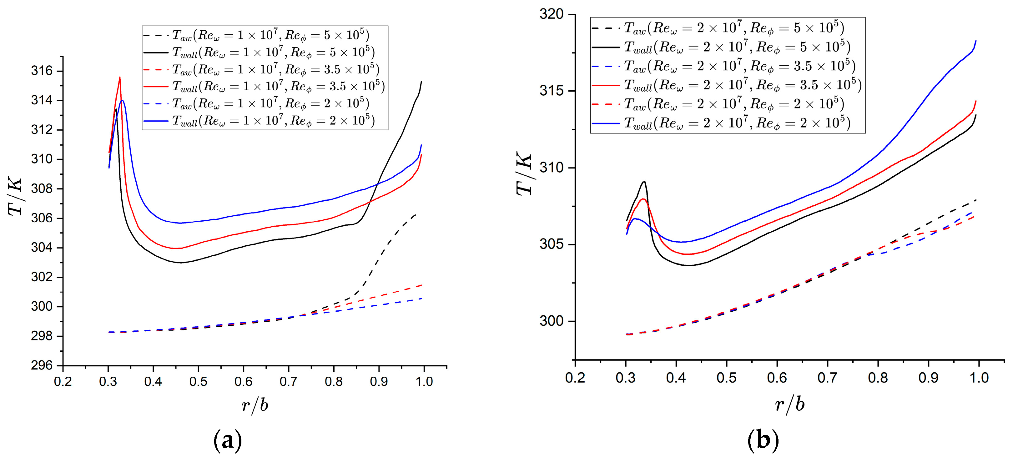
However, one case ( R e ω = 1 × 10 7 , R e φ = 5 × 10 5 ) serves as an exception. In this case, both the adiabatic wall temperature and wall temperature exhibit significantly faster growth rates in the region where r/b > 0.85. The streamline visualization reveals that in this case, large-scale vortices generated on the upstream disk side at high radius actively entrain high-temperature fluid from the high-radius inlet and transport it toward the downstream disk. This significantly enhances thermal energy exchange between the high-temperature fluid and fluid near the downstream disk.
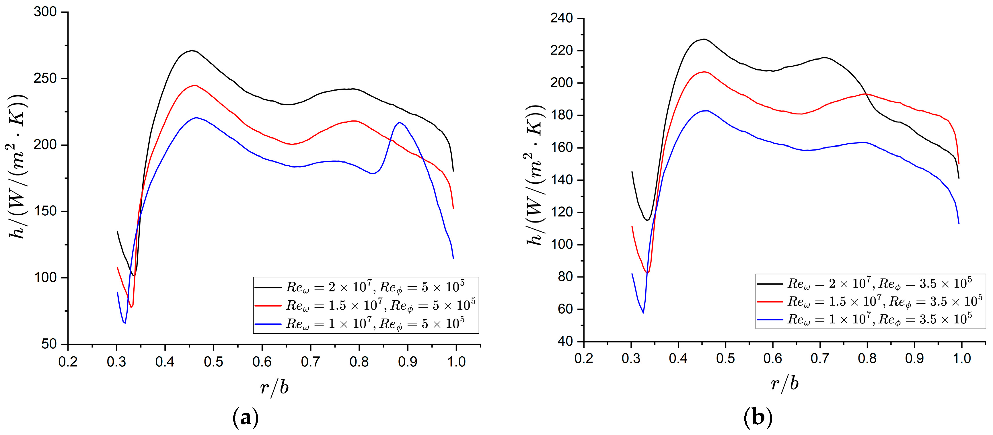
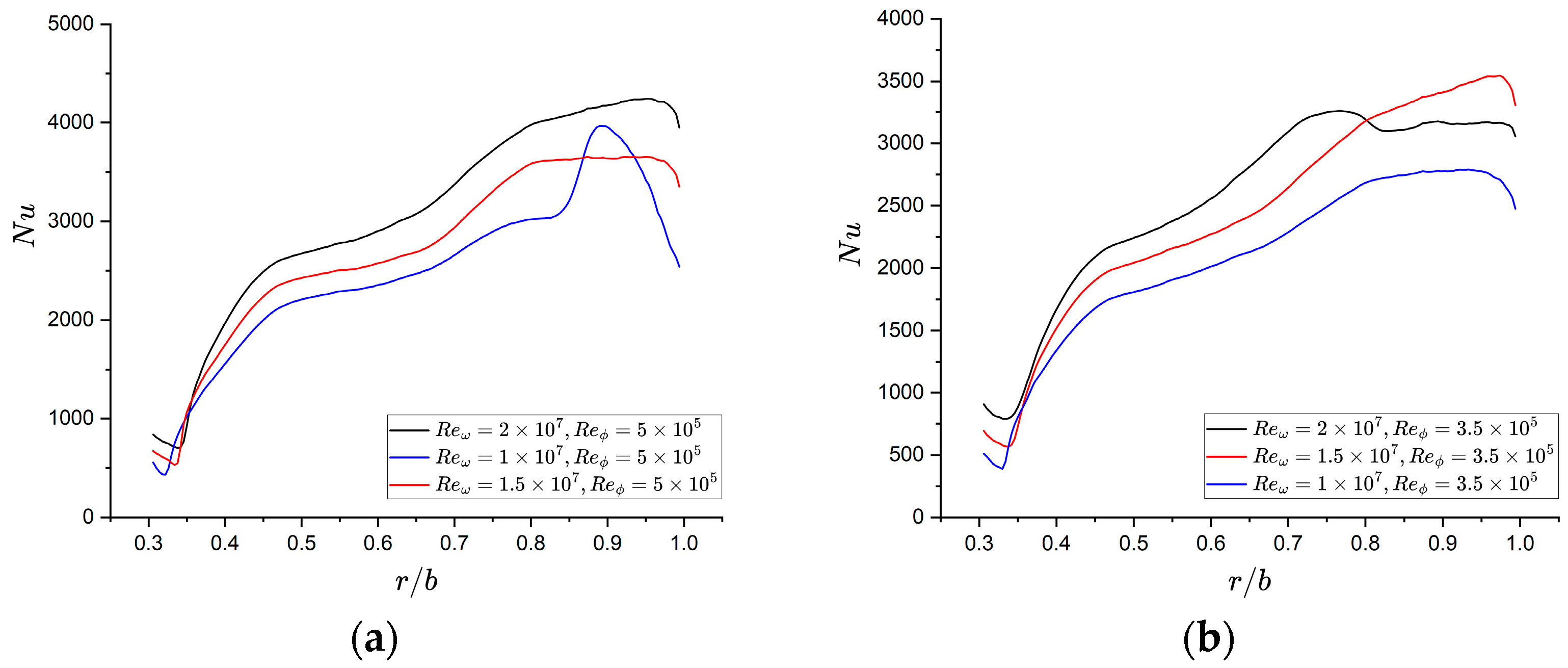
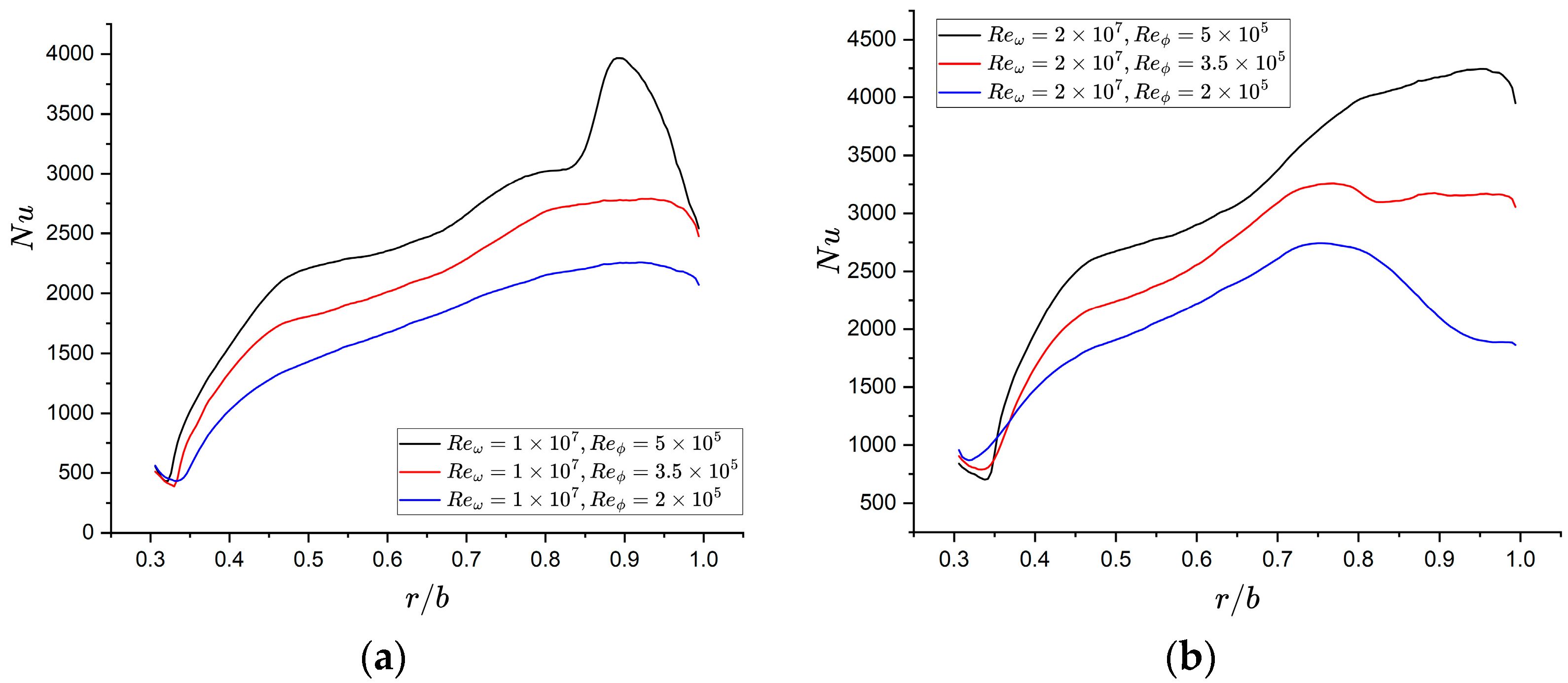
The convective heat transfer coefficient on the downstream disk, as shown in Figure 9, exhibits a characteristic trend: values remain relatively low in the r/b = 0.3–0.35 region. This area remains unaffected by direct impingement from the central inlet flow, resulting in relatively poor heat transfer performance. The convective heat transfer coefficient then increases rapidly along the radial direction, reaching a peak at approximately r/b = 0.5. The convective heat transfer coefficient then undergoes a mild fluctuation—initially decreasing, then increasing, before decreasing again. The values reach another peak at approximately r/b = 0.8. Correspondingly, the Nusselt number exhibits alternating regions of rapid and gradual growth along the radial direction, as shown in Figure 10.
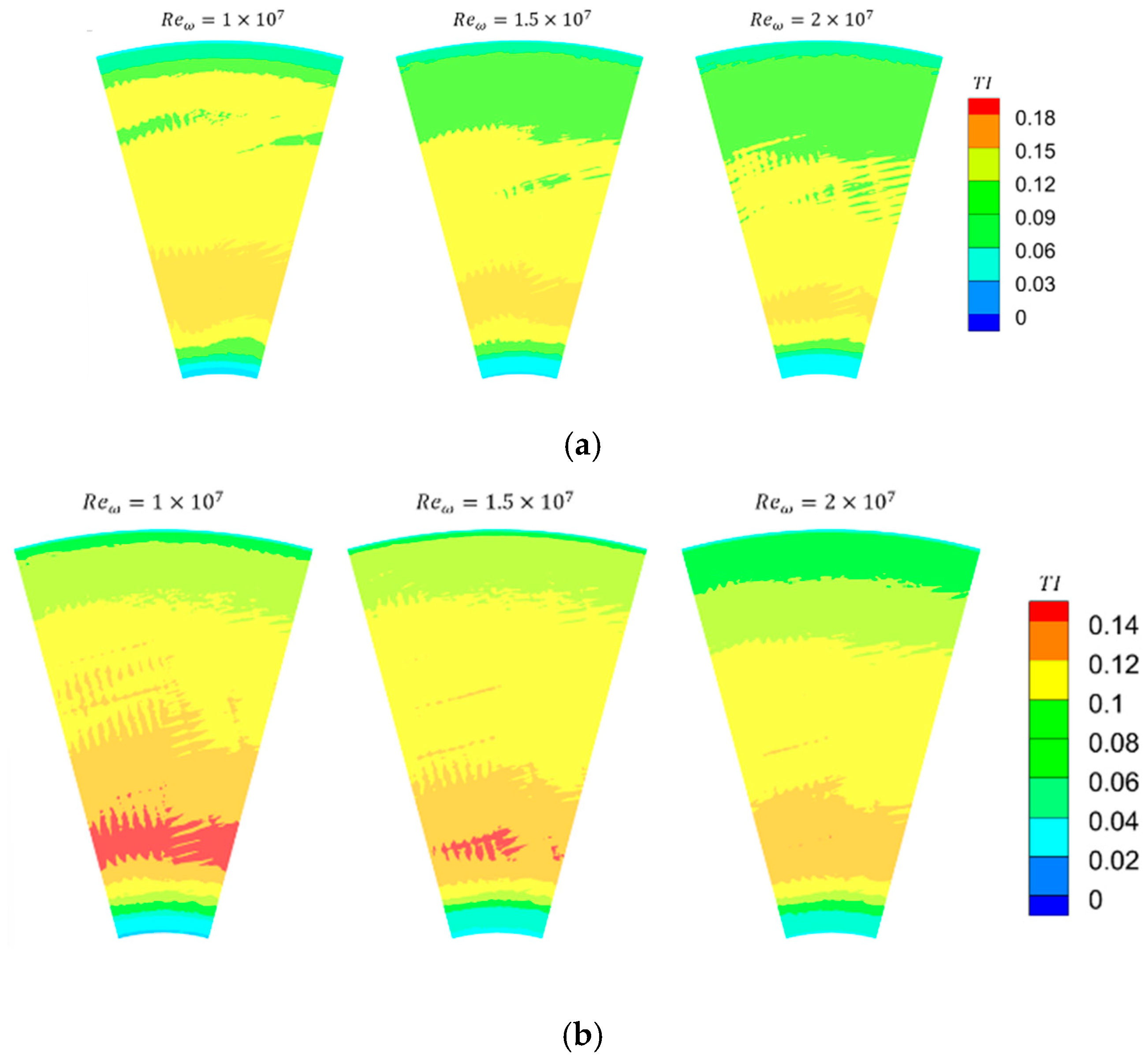
For the case with R e ω = 1 × 10 7 , R e φ = 5 × 10 5 , the turbulence intensity contour plots clearly show significantly enhanced turbulence levels at high radius, leading to markedly improved heat transfer performance, as shown in Figure 11. In contrast, another case ( R e ω = 2 × 10 7 , R e φ = 3.5 × 10 5 ) demonstrates the opposite behavior, with the turbulence intensity at high radius being significantly lower compared to cases at other rotational speeds. This suppression effect on heat transfer outweighs the enhancement caused by the thinner boundary layer, ultimately leading to reductions in both the convective heat transfer coefficient and Nusselt number.
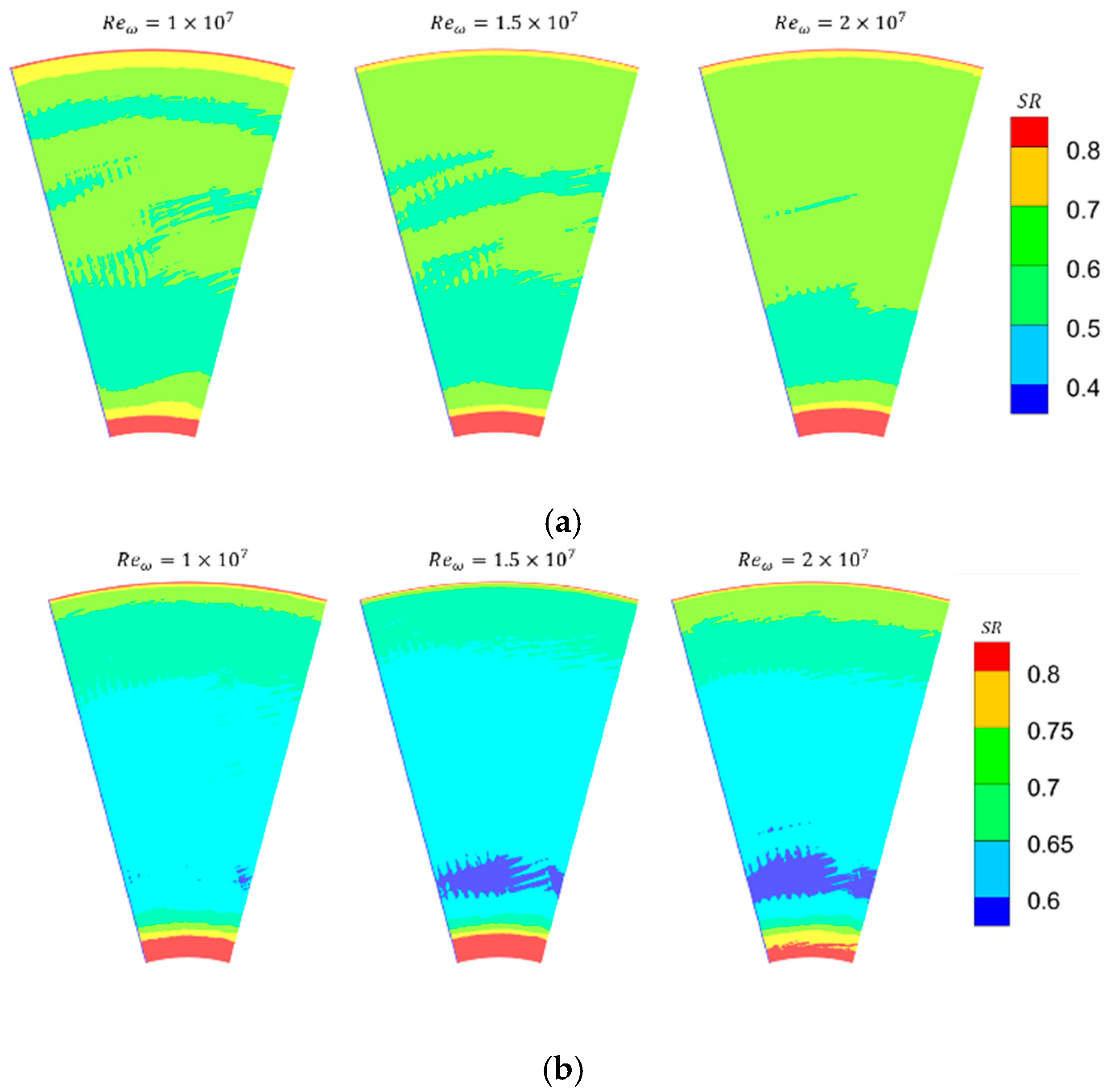
Overall, the convective heat transfer coefficient and Nusselt number increase with rotational speed, demonstrating the enhanced heat transfer capability of near-wall fluid at the higher rotation speed. The swirl ratio contour plots reveal minimal differences in the swirl ratio of fluids near the downstream disk across various rotational speeds, as shown in Figure 12. However, increasing the rotational speed enlarges the differential rotational linear velocity between the disk and adjacent fluids, resulting in enhanced shear stress, thinning of the boundary layer, and consequent heat transfer intensification.

3.3. Influence of Mass Flow Rate on Heat Transfer

Figure 13 shows the adiabatic wall temperature and wall temperature of the downstream disk for different rotational Reynolds numbers and jet Reynolds numbers. It can be observed that when the rotational speed is held constant, the variation in flow rate has minimal impact on the adiabatic wall temperature in the region where r/b < 0.75. In the region where r/b > 0.75, the adiabatic wall temperature exhibits a slight increase with rising flow rate. This indicates that mass flow rate increases, when insufficient to significantly alter the internal flow structure, have limited effects on fluid mixing and heat transfer within the cavity. In addition, the wall temperature decreases with increasing flow rate in most cases. The exceptional case ( R e ω = 1 × 10 7 , R e φ = 5 × 10 5 ) has been previously discussed.
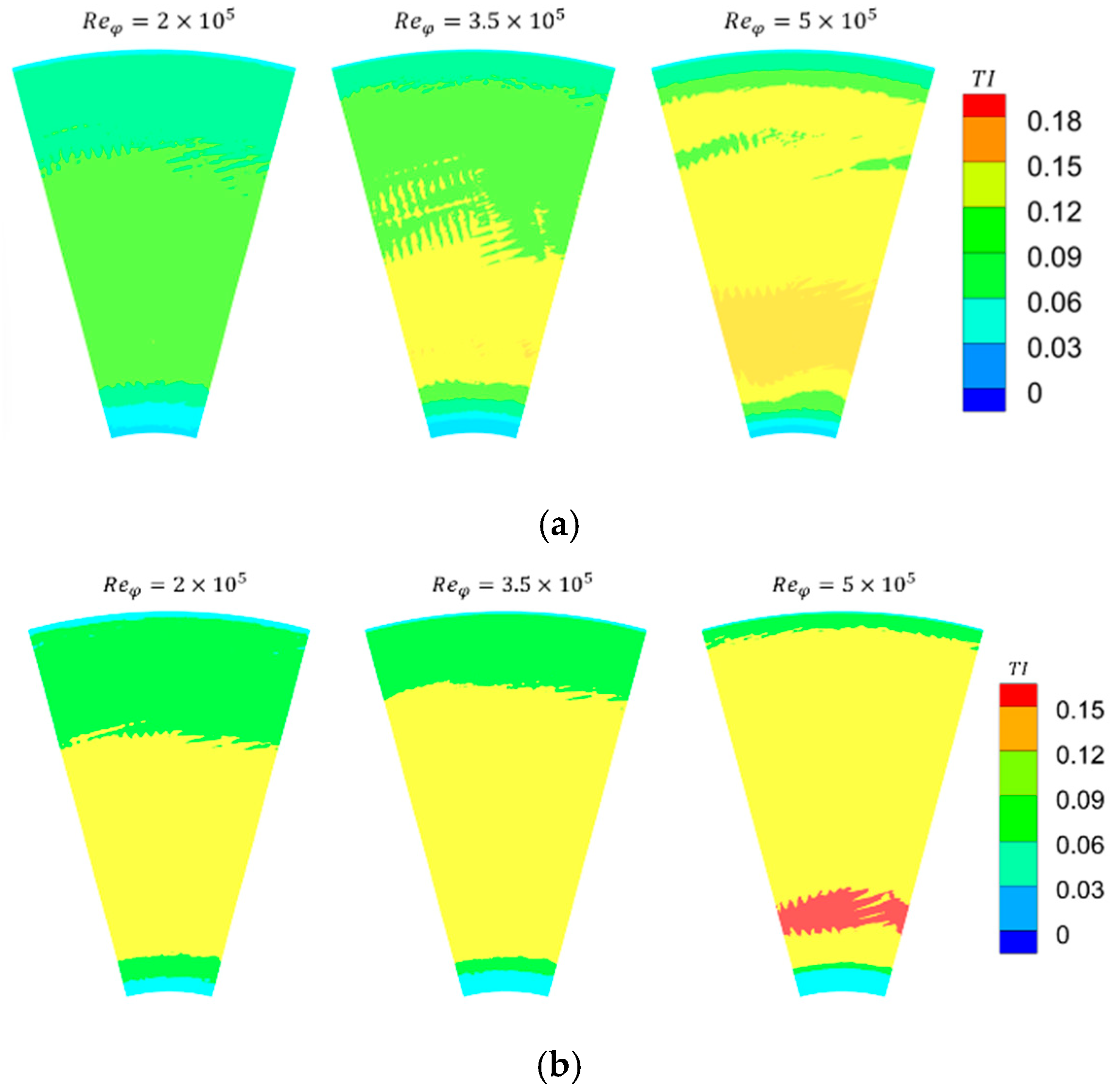
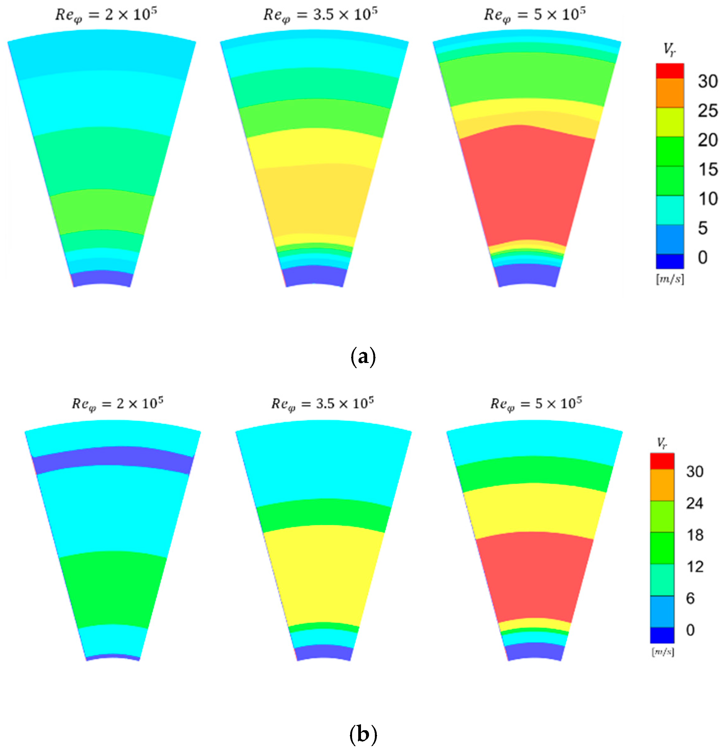
As can be observed from Figure 14 and Figure 15, both the convective heat transfer coefficient and Nusselt number increase with rising mass flow rate. This phenomenon primarily stems from two mechanisms. As the flow rate increases, the turbulence intensity of the fluid near the downstream disk generally rises, thereby enhancing heat transfer, as shown in Figure 16. Figure 17 exhibits the radial velocity distribution in the r-φ plane. The results demonstrate that increasing the flow rate significantly intensifies radial flow near the wall, leading to a thinner boundary layer.

4. Conclusions

This study focuses on a rotating disk cavity with two inlets and one outlet, employing the CFD approach to investigate the flow structure in the cavity and the heat transfer characteristics on the disk surface. This study also analyzes the effects of different mass flow rates and rotation speeds on heat transfer. The following conclusions are drawn:
  • A large-scale vortex is induced by the central inlet jet in the low-radius region of the cavity. The flow structure in the high-radius region is significantly influenced by both rotational speed and flow rate. When inertial effects dominate, the high-radius inlet jet induces a vortex on the upstream disk side. When rotational effects dominate, a vortex appears near the downstream disk.
  • Increasing the rotational speed generally enhances the wall heat transfer capability. This enhancement occurs because higher rotational speeds amplify the differential rotational linear velocity between the disk surface and nearby wall flow, consequently thinning the boundary layer.
  • Increasing the mass flow rate enhances heat transfer through two primary mechanisms: first, it elevates the turbulence intensity of the near-wall fluid; second, the higher radial velocity results in a thinner boundary layer.
We plan to conduct numerical simulations across a broader range of operating conditions and perform heat transfer experiments on rotating disk cavities with two inlets and one outlet. Based on an in-depth analysis of the flow and heat transfer characteristics within the cavity, we aim to derive a reliable empirical correlation for the convective heat transfer coefficient. We believe this study can yield an empirically applicable formula for engineering purposes, thereby contributing to the optimized design of secondary air systems.

Author Contributions

Conceptualization, H.X., X.L., and J.R.; Formal analysis, H.X.; Funding acquisition, X.L. and J.R.; Investigation, H.X.; Methodology, H.X.; Project administration, X.L. and J.R.; Supervision, X.L. and J.R.; Visualization, H.X.; Writing—original draft, H.X.; Writing—review and editing, H.X., X.L., and J.R. All authors have read and agreed to the published version of the manuscript.

Funding

This research was funded by the National Science and Technology Major Project (Y2022-III-0003-0012).

Data Availability Statement

The data presented in this study are not readily available because the data are part of an ongoing study. Requests to access the datasets should be directed to the corresponding author.

Conflicts of Interest

The authors declare no conflicts of interest.

Abbreviations

The following abbreviations are used in this manuscript:
CFDComputational Fluid Dynamics
LDALaser Doppler Anemometry
SIMPLESemi-Implicit Method for Pressure Linked Equations
RNGRe-Normalization Group

References

  1. Lentini, M.; Keller, H. Von Karman Swirling Flows. Siam J. Appl. Math. 1980, 38, 52–64. [Google Scholar] [CrossRef]
  2. Farthing, P.R.; Long, C.A.; Owen, J.M.; Pincombe, J.R. Rotating Cavity with Axial Throughflow of Cooling Air: Flow Structure. J. Turbomach. 1992, 114, 237–246. [Google Scholar] [CrossRef]
  3. Bohn, D.; Ren, J.; Tuemmers, C. Investigation of the unstable flow structure in a rotating cavity. In Proceedings of the 51st ASME Turbo Expo 2006, New York, NY, USA, 8–11 May 2006. [Google Scholar]
  4. Tian, S.; Tao, Z.; Ding, S.; Xu, G. Investigation of flow instability in rotating cavity with axial throughflow of cooling air. J. Beijing Univ. Aeronaut. Astronaut. 2005, 31, 393–396. [Google Scholar] [CrossRef]
  5. Alexiou, A.; Hills, N.J.; Long, C.A.; Turner, A.B. Heat transfer in high-pressure compressor gas turbine internal air systems: A rotating disc-cone cavity with axial throughflow. Exp. Heat Transf. 2000, 13, 299–328. [Google Scholar] [CrossRef]
  6. Tian, S.; Tao, Z.; Ding, S.; Xu, G. Computation of buoyancy-induced flow in a heated rotating cavity with an axial throughflow of cooling air. Int. J. Heat Mass Transf. 2008, 51, 960–968. [Google Scholar] [CrossRef]
  7. Quan, J.; Luo, X.; Peng, Y.; Hu, Y. Numerical Study of Heat Transfer Characteristics Inside Counter-Rotating Disk Cavity. J. Propuls. Technol. 2018, 39, 2813–2819. [Google Scholar] [CrossRef]
  8. Jackson, R.; Tang, H.; Scobie, J.A.; Owen, J.M.; Lock, G.D. Measurement of Heat Transfer and Flow Structures in a Closed Rotating Cavity. J. Eng. Gas Turbines Power 2022, 144, 051005. [Google Scholar] [CrossRef]
  9. Bai, L.; Feng, Q.; Liu, S. Numerical investigation of turbulence parameter on flow field of rotating disc cavity with complex geometry. J. Propuls. Technol. 2003, 24, 344–347. [Google Scholar] [CrossRef]
  10. Guo, J.; Li, Q. Numerical Study of Flow Structure and Heat Transferin Rotating Cavity with Axial Throughflow. J. Propuls. Technol. 2018, 39, 1790–1796. [Google Scholar] [CrossRef]
  11. Wu, Z.; Luo, X.; Zhu, J.; Zhang, Z.; Liu, J. A Method of Solving Three Temperature Problem of Turbine with Adiabatic Wall Temperature. In Proceedings of the ASME Turbomachinery Technical Conference and Exposition (Turbo Expo)—Sustainable Energy—Accelerating the Transition by Advancing Turbine Technology, New York, NY, USA, 7–11 June 2021. [Google Scholar]
  12. Li, Z.; Hu, P.; Sui, X.; Zhao, W.; Lin, Q. Flow structures and heat transfer characteristics in a vaneless counter-rotating turbine cavity with different cooling inflows. Proc. Inst. Mech. Eng. Part A J. Power Energy 2023, 237, 656–668. [Google Scholar] [CrossRef]
  13. Bohn, D.E.; Deutsch, G.N.; Simon, B.; Burkhardt, C. Flow Visualisation in a Rotating Cavity with Axial Throughflow. In Proceedings of the ASME Turbo Expo 2000: Power for Land, Sea, and Air, Munich, Germany, 8 May 2000. [Google Scholar] [CrossRef]
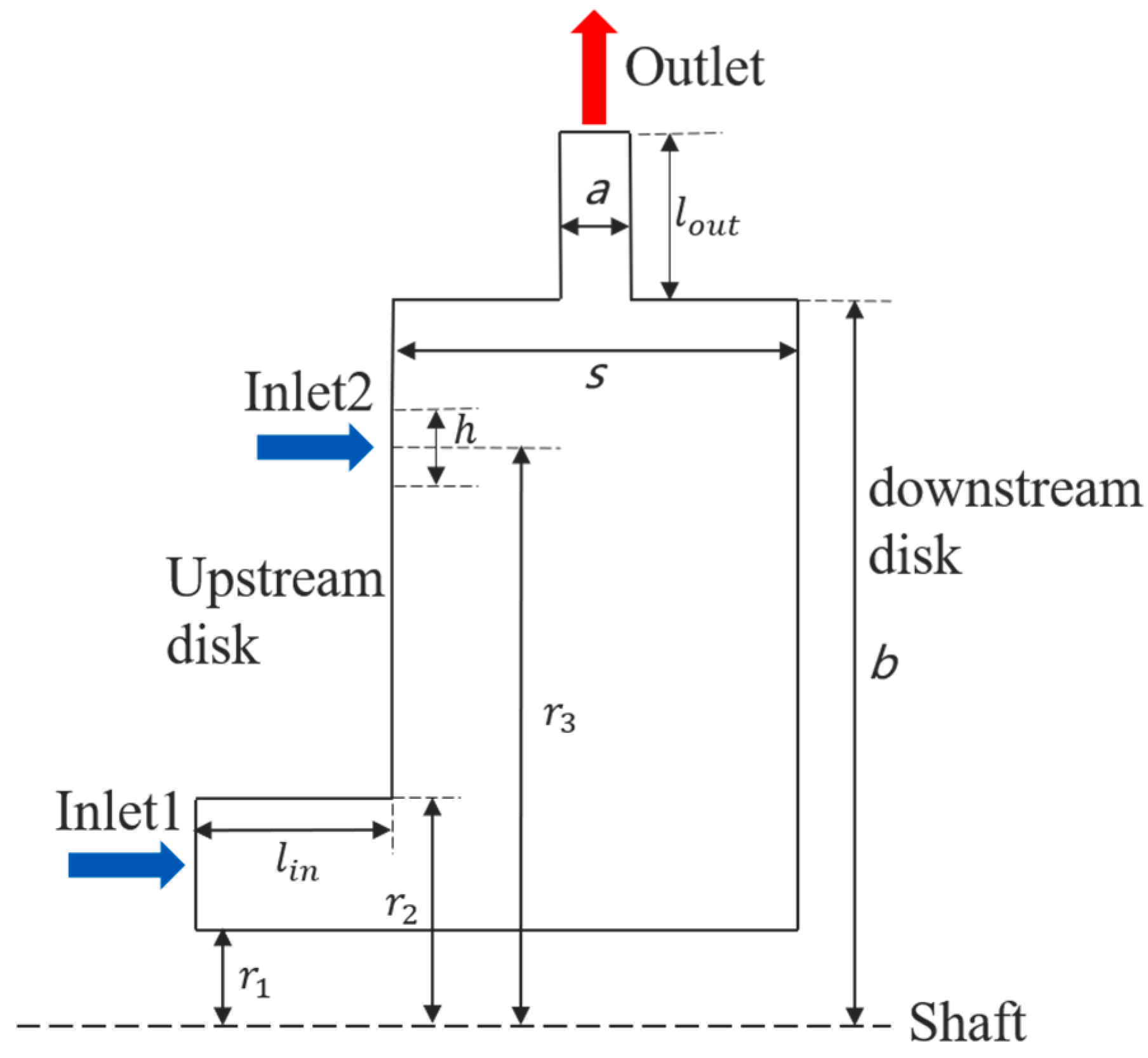
Figure 1. Model of the cavity.
Energies 18 05049 g001
Figure 2. Temperature and streamlines distribution in r-φ plane.
Energies 18 05049 g002
Figure 3. Mesh independence study.
Energies 18 05049 g003
Figure 4. Mesh division of the model (blue arrows indicate inlet gas).
Energies 18 05049 g004
Figure 5. Model used in validation.
Energies 18 05049 g005
Figure 6. Nusselt number of disk surface [13]: (a) upstream disk; (b) downstream disk.
Energies 18 05049 g006
Figure 7. Flow structure in the cavity in different cases of Re number.
Energies 18 05049 g007
Figure 8. Temperature of downstream disk: (a) R e φ = 5 × 10 5 ; (b) R e φ = 3.5 × 10 5 .
Energies 18 05049 g008
Figure 9. Convective heat transfer coefficient of downstream disk: (a) R e φ = 5 × 10 5 ; (b) R e φ = 3.5 × 10 5 .
Energies 18 05049 g009
Figure 10. Nusselt number of downstream disk: (a) R e φ = 5 × 10 5 ; (b) R e φ = 3.5 × 10 5 .
Energies 18 05049 g010
Figure 11. Turbulent intensity distribution in r-φ plane: (a) R e φ = 5 × 10 5 ; (b) R e φ = 3.5 × 10 5 .
Energies 18 05049 g011
Figure 12. Swirl ratio distribution in r-φ plane: (a) R e φ = 5 × 10 5 ; (b) R e φ = 3.5 × 10 5 .
Energies 18 05049 g012
Figure 13. Temperature of downstream disk: (a) R e ω = 1 × 10 7 ; (b) R e ω = 2 × 10 7 .
Energies 18 05049 g013
Figure 14. Convective heat transfer coefficient of downstream disk: (a) R e ω = 1 × 10 7 ; (b) R e ω = 2 × 10 7 .
Energies 18 05049 g014
Figure 15. Nusselt number of downstream disk: (a) R e ω = 1 × 10 7 ; (b) R e ω = 2 × 10 7 .
Energies 18 05049 g015
Figure 16. Turbulent intensity distribution in r-φ plane: (a) R e ω = 1 × 10 7 ; (b) R e ω = 2 × 10 7 .
Energies 18 05049 g016
Figure 17. Radial velocity distribution in r-φ plane: (a) R e ω = 1 × 10 7 ; (b) R e ω = 2 × 10 7 .
Energies 18 05049 g017
Table 1. Geometric parameters of the model.
Edge/mmLength
b500
r 1 150
r 2 172.5
r 3 400
l i n 187.5
s100
a10
h 3
l o u t 50
Disclaimer/Publisher’s Note: The statements, opinions and data contained in all publications are solely those of the individual author(s) and contributor(s) and not of MDPI and/or the editor(s). MDPI and/or the editor(s) disclaim responsibility for any injury to people or property resulting from any ideas, methods, instructions or products referred to in the content.