Article

Thermal Performance Study of a Novel Double-Phase Cooling Strategy in Electric Vehicle Battery Systems

by
Federico Sacchelli
1,
Luca Cattani
1,2,* and
Fabio Bozzoli
1,2
1
Department of Engineering for Industrial Systems and Technologies, University of Parma, Parco Area delle Scienze 181/A, 43124 Parma, Italy
2
SITEIA.PARMA Interdepartmental Centre, University of Parma, Parco Area delle Scienze 181/A, 43124 Parma, Italy
*
Author to whom correspondence should be addressed.
Energies 2025, 18(18), 4937; https://doi.org/10.3390/en18184937
Submission received: 10 August 2025 / Revised: 12 September 2025 / Accepted: 14 September 2025 / Published: 17 September 2025

Abstract

In recent years, interest in lithium-ion batteries has grown significantly due to their dominance in electric mobility, driven by their high energy density. However, their performance and longevity are strongly influenced by the effectiveness of heat dissipation and thermal management. The literature indicates that battery temperature should be maintained within the optimal range of 20–40 °C, while also ensuring minimal temperature gradients within the battery pack. In this study, a thermal management system for electric vehicle batteries which combines two different cooling approaches (i.e., direct immersion cooling and pulsating heat pipes) is presented. In particular, the battery pack is placed inside a PVC case and completely submerged by a low-boiling dielectric fluid (Tbp = 33.4 °C at 1 atm) to take advantage of the excellent thermal properties of the liquid and of the latent heat during phase change. The evaporator section of the pulsating heat pipe is positioned in the vapor phase region of the dielectric fluid, while the condenser section is located outside the PVC box and cooled by an airflow in natural convection. This setup is a completely passive system. To evaluate the cooling performance of the dual two-phase cooling system, tests were conducted on the battery pack at three different discharge C-rates 0.5C, 1C, and 2C that reproduce the working conditions of a real-world battery. To evaluate the effectiveness of the new setup, its performance was compared with cooling based on natural convection and direct immersion cooling alone. These approaches were assessed under two controlled ambient temperatures—5 °C and 20 °C—to compare their performance in varying conditions. The results show that the hybrid system performs particularly well, especially because it can operate passively without requiring external power or active control mechanisms.

1. Introduction

Over the past years, rising awareness of air pollution and climate change has brought the idea of ecological transition to the forefront. At its core, this transition seeks to lessen our dependence on fossil fuels and harmful emissions—particularly carbon dioxide (CO2). In this broader push for sustainability, electrification has emerged as a key strategy. When electricity is generated through renewable sources like wind or solar power, it offers a cleaner alternative that can significantly lower pollution levels. This trend is particularly evident in the automotive industry, where electric vehicles (EVs) are gaining traction. The development of high-performance batteries has played a crucial role in this growth, overcoming early challenges such as limited driving range and low power output. Faster charging technology has helped cut down charging times, making it easier for more people to switch to electric vehicles (EVs) [1]. Today, there are many types of batteries used in cars, each with different materials and designs. These differences affect how the batteries perform. Two of the most important factors are specific energy and specific power, which help make the batteries lighter without losing performance [2].
Lithium-ion (Li-ion) batteries are currently considered the leading technology for the electrification of mobility due to their numerous advantages over other battery types [3]. Available in various cell formats and chemistries, Li-ion batteries are known for their high energy storage capacity, favorable energy-to-weight ratio, and low self-discharging [4]. This is largely attributed to lithium’s high electrochemical potential and low atomic mass. These batteries are also known for their high efficiency and long lifespan, with plenty of potential for further improvement [5,6].
However, as battery technology continues to develop, the amount of heat produced by battery modules increases, which raises their operating temperatures. Temperature is a key factor because it directly affects both how well the battery performs and how long it lasts. For lithium-ion batteries, the ideal operating temperature is usually between 20 °C and 40 °C, so proper thermal management is essential [7,8]. At lower temperatures, the battery’s performance drops due to increased internal resistance and lithium plating, which also speeds up aging [9,10]. This study focuses on problems related to high temperatures, which are a major concern for lithium-ion batteries. Many studies have shown that heat is mostly produced during charging and discharging. High temperatures can harm battery performance by speeding up the loss of capacity and power, increasing the rate of self-discharge, and leading to significant energy loss over time [11]. Besides reduced performance at high temperatures, each cell in a battery pack can overheat due to short circuits or very high external temperatures. This can trigger one of the most critical safety issues in batteries: thermal runaway. When the battery temperature rises continuously and the generated heat cannot be dissipated in time, thermal runaway occurs, generally once the temperature exceeds 80 °C. This process leads to a rapid and uncontrollable increase in temperature, often accompanied by the release of harmful gases, smoke, fire, and in severe cases, explosions [12].
To ensure batteries operate efficiently, it is not only important to manage extreme temperatures but also to maintain a uniform temperature across all cells and modules [13]. When temperatures vary within a battery pack, it can lead to differences in how individual cells charge, discharge, and perform chemically. This uneven behavior causes some cells to age faster than others, reducing the overall performance and lifespan of the battery [14]. Even a small temperature difference of just 5 °C can cut power capability by around 10% [15]. Therefore, to maximize performance and longevity, it is recommended that the temperature variation between individual cells and modules does not exceed 5 °C [7].
To maintain battery operating temperatures within optimal limits, Battery Thermal Management Systems (BTMS) are used to control the temperature of battery packs, dissipating excess heat and preventing performance loss [16]. The literature presents several cooling methods, with air cooling being one of the most basic. Traditional battery thermal management systems often use air cooling, relying on components like fans and fins to improve airflow and help remove heat [17,18]. While these systems are simple and cost-effective, they often fall short in high-power applications—such as electric vehicles (EVs)—where the amount of heat generated is too much for air alone to handle effectively. In such scenarios, liquid-based cooling systems have become the preferred alternative due to their higher thermal conductivity and superior capacity for heat absorption and transfer [19,20]. Among these, direct liquid cooling configurations—where the coolant comes into close thermal contact with the battery cells—have attracted significant attention for their ability to deliver precise and consistent temperature regulation in lithium-ion battery packs used in EVs [21,22,23].
At the same time, researchers are exploring advanced thermal management technologies to improve the performance and safety of battery systems [24,25]. One effective method is the use of Phase Change Materials (PCMs) [26,27], which absorb and release large amounts of heat during melting and solidifying. This helps control temperature spikes during fast charging or discharging. Another promising solution is represented by the heat pipes [28,29,30], which are passive two-phase heat transfer devices. Heat pipes offer high thermal conductivity, quick response times, and reliable operation—even in harsh or changing conditions—making them well-suited for electric vehicles (EVs).
Recent research in battery thermal management has increasingly emphasized the development of hybrid cooling systems that integrate multiple techniques to capitalize on their respective advantages. A hybrid BTMS typically combines either active and passive approaches or two different passive strategies, with the overarching objective of enhancing thermal uniformity, operational reliability, and overall safety. Among the most extensively investigated configurations are PCM coupled with air circulation, PCM with liquid circulation, and PCM integrated with heat pipes. These systems exploit the high latent heat capacity of PCMs to buffer temperature fluctuations, while the accompanying convective or conductive elements facilitate the dissipation of accumulated heat [31,32]. Despite the progress achieved in this field, relatively few studies have examined hybrid solutions involving two-phase liquid cooling, particularly in configurations that function entirely under passive mechanisms without the aid of external pumping or forced circulation. This gap in the literature is noteworthy, as two-phase cooling systems inherently possess the ability to deliver high heat transfer coefficients and self-regulating thermal performance, while simultaneously preserving structural simplicity and minimizing energy consumption. Addressing this underexplored area, the present work proposes an advanced hybrid thermal management system that integrates two-phase liquid cooling with pulsating heat pipes [33]. PHPs are passive devices that use capillary action inside sealed tubes with alternating hot (evaporator) and cold (condenser) zones [34]. The fluid moves on its own through phase changes and surface tension, creating a self-sustained and efficient way to transfer heat. PHPs are known for being simple, low-cost, and passive, making them a strong fit for advanced battery cooling systems [35].
This work focuses on experimentally testing the proposed dual two-phase cooling system that combines high thermal performance with passive operation under realistic EV conditions, using full discharge cycles at steady currents with 0.5C, 1C, and 2C rates. The results showed that this cooling system keeps the battery within the ideal temperature range, even under heavy use. Overall, the findings highlight the system’s strong potential, especially since it operates entirely without active power input. This characteristic eliminates the need for supplementary power sources or complex control systems, thereby simplifying integration and improving overall system efficiency

2. Experimental Setup

The proposed Battery Thermal Management System is a fully passive solution that combines two distinct two-phase cooling methods: direct immersion cooling using a low-boiling dielectric fluid, and a pulsating heat pipe system (see Figure 1). In the experimental setup, the battery cells were submerged in a dielectric fluid inside a transparent PVC enclosure. This setup takes advantage of the fluid’s high thermal capacity and its ability to absorb heat through vaporization, allowing it to effectively manage heat during low to medium discharge rates. However, under high loads or in hot environments, the fluid can reach its boiling point. At that stage, the liquid begins to evaporate, creating a mix of liquid and vapor in balance. In the sealed battery case, any further rise in temperature leads to increased internal pressure, which could raise safety concerns.
To prevent sudden temperature spikes and improve overall system reliability, a pulsating heat pipe (PHP) was added to the design. These passive devices help dissipate heat, encourage condensation of the dielectric fluid vapor, and keep battery temperatures within a safe range. The entire system runs without external power, making it both energy-efficient and cost-effective for thermal management.
For the direct immersion cooling, the dielectric fluid Opteon® SF-33 (Chemours, Wilmington, DE, USA) was chosen because of its low boiling point—33.4 °C at atmospheric pressure—which falls within the optimal temperature range for lithium-ion batteries (20–40 °C). This allows the system to efficiently remove heat using the fluid’s latent heat of vaporization, which is much more effective than just using sensible heat. Other properties that make Opteon® SF-33 suitable for this application include its high electrical resistivity and low dielectric constant, reducing the risk of electrical problems from direct contact with battery components. Furthermore, its non-flammable nature increases system safety in the event of thermal runaway, lowering the risk of fire. Within the system, the dielectric fluid remains in a dynamic equilibrium between its liquid and vapor phases.
The PHP used in this study measures 400 mm in length, 100 mm in width, and 300 mm in height, and is divided into three sections: an evaporator, a condenser, and an adiabatic section. These sections have a height of 90 mm, 90 mm, and 20 mm, respectively. Heat is absorbed at the evaporator, and the combination of liquid and vapor bubble movement drives heat transfer toward the condenser, where it is released into the environment. In this prototype (see Figure 1), the evaporator section of the PHP is positioned within the region of the PVC enclosure in which the presence of dielectric fluid vapor phase is expected, while the condenser extends outside the box, where it dissipates heat through natural air convection. The PHP was constructed using a stainless-steel tube with an inner radius of 1.76 mm and an outer radius of 3.18 mm, coiled to form a 3D structure featuring three rows of 11 turns loops. Stainless steel was chosen for its cost-effectiveness and widespread availability—important considerations for devices intended for large-scale manufacturing. The pipe is first evacuated and then partially filled to a specified filling ratio (50%) with HFC-134a. Prior characterization of the device in terms of overall thermal resistance demonstrated that this filling ratio provides the best trade-off between startup efficiency and stable oscillatory motion, while minimizing the occurrence of dry-out and ensuring robust thermal performance [36]. Based on the preliminary results, the current configuration was selected.
The proposed BTMS was developed for real-world applications with a battery pack consisting of six SKI E566 cells connected in series. Each cell delivers a nominal voltage of 3.5 V and a capacity of 55.6 Ah. These types of battery cells, along with similar configurations, are commonly used in electric vehicle systems [37]. As a preliminary study to evaluate the cooling performance of the proposed BTMS, the thermal behavior of a six-cell pack was simulated using four aluminum plates. Aluminum was chosen due to its specific heat capacity of 0.9 kJ/(kg·K), which lies within the acceptable margin of error compared to the typical values reported for Li-ion pouch cells (1.0–1.2 kJ/(kg·K)). These plates were designed to match the thermal capacity of the actual battery pack, enabling the prototype to closely mimic the real physical and thermal behavior of an actual battery system. They were heated using polyimide-insulated flexible heaters (OMEGA KHLVA-105/10-P) adhered to their surfaces. The heaters were powered by programmable DC power suppliesAIM-EX354RT (TTI INSTRUMENTS, Huntingdon, UK) which provide a current accuracy of 0.5% within the 0–5 A range and a resolution of 1 mA. They also offer voltage accuracy of 0.3% in the 0–70 V range, with a resolution of 10 mV. Although the setup does not capture the localized thermal behavior of individual cells, it provides a reliable approximation of the overall thermal response of the battery pack, while simplifying the experimental procedure and avoiding the additional complexity and safety risks associated with real Li-ion cells. The plates were assembled and placed in the center of a transparent PVC box measuring 420 × 135 × 227 mm.
To evaluate the individual contributions of each cooling method integrated into the proposed BTMS, the battery discharge process was tested under three distinct thermal management configurations: (i) natural convection, (ii) direct immersion cooling, and (iii) direct immersion cooling combined with a PHP.
In detail:
(i)
Natural convection refers to the battery pack being exposed directly to ambient air without any forced cooling or insulation.
(ii)
Direct immersion cooling means placing the battery pack inside a low-boiling-point fluid held in a tank.
(iii)
The full hybrid setup combines this immersion cooling with a PHP, which helps transfer heat from the fluid to the surrounding air.
This comparative approach enables a quantitative assessment of the cooling performance improvements offered by each method and helps to justify the added complexity introduced by the hybrid system.
For each setup, the battery is discharged at three different discharge C-rates: 0.5, 1C, and 2C. All experiments were performed at two different ambient temperatures of 5 °C and 20 °C to consider the effect of environment on the cooling system. The environmental temperature is guaranteed by two thermal chambers, operating, respectively, from −20° to 0 °C and ambient to 35 °C, and connected via a crossflow heat exchanger. To ensure accuracy and repeatability, each test is performed twice.
For thermal monitoring, multiple Type T thermocouples (Copper-Constantan) characterized by a measurement uncertainty of ±0.1 °C were strategically placed: some on the aluminum plates and others in both the liquid and vapor regions of the dielectric coolant, Opteon SF-33, to observe its behavior in both phases. Additional sensors were installed on the evaporator and condenser branches of the PHP. To ensure precise temperature measurement, all thermocouples were connected to an ice point reference. Pressure within the system was monitored using a Kulite® XTL-190S-1000 PSI SG pressure sensor (Kulite Semiconductor Products, Inc., One Willow Tree Road, Leonia, NJ, USA) embedded in the enclosure. The pressure transducer and thermocouples output were logged using an AGILENT 34970A data acquisition system, capable of 0.076 mV resolution in the 0–10 V input range, with an overall uncertainty of ±0.25 mV. A schematic representation of the experimental setup is shown in Figure 2.

3. Results and Discussion

As mentioned in the previous paragraph, to assess the effectiveness of the proposed cooling system under realistic battery operating conditions, experimental tests were performed using aluminum blocks subjected to controlled power loads. These loads simulated the thermal energy typically generated during three distinct battery discharge processes. The discharge scenarios replicated full depletion cycles conducted at constant current values, corresponding to discharge rates of 0.5C, 1C, and 2C. The heat generation from a single battery cell was estimated using the Bernardi equation [38,39]:
Q = I · ( V     U O C ) +   I · T · U O C T
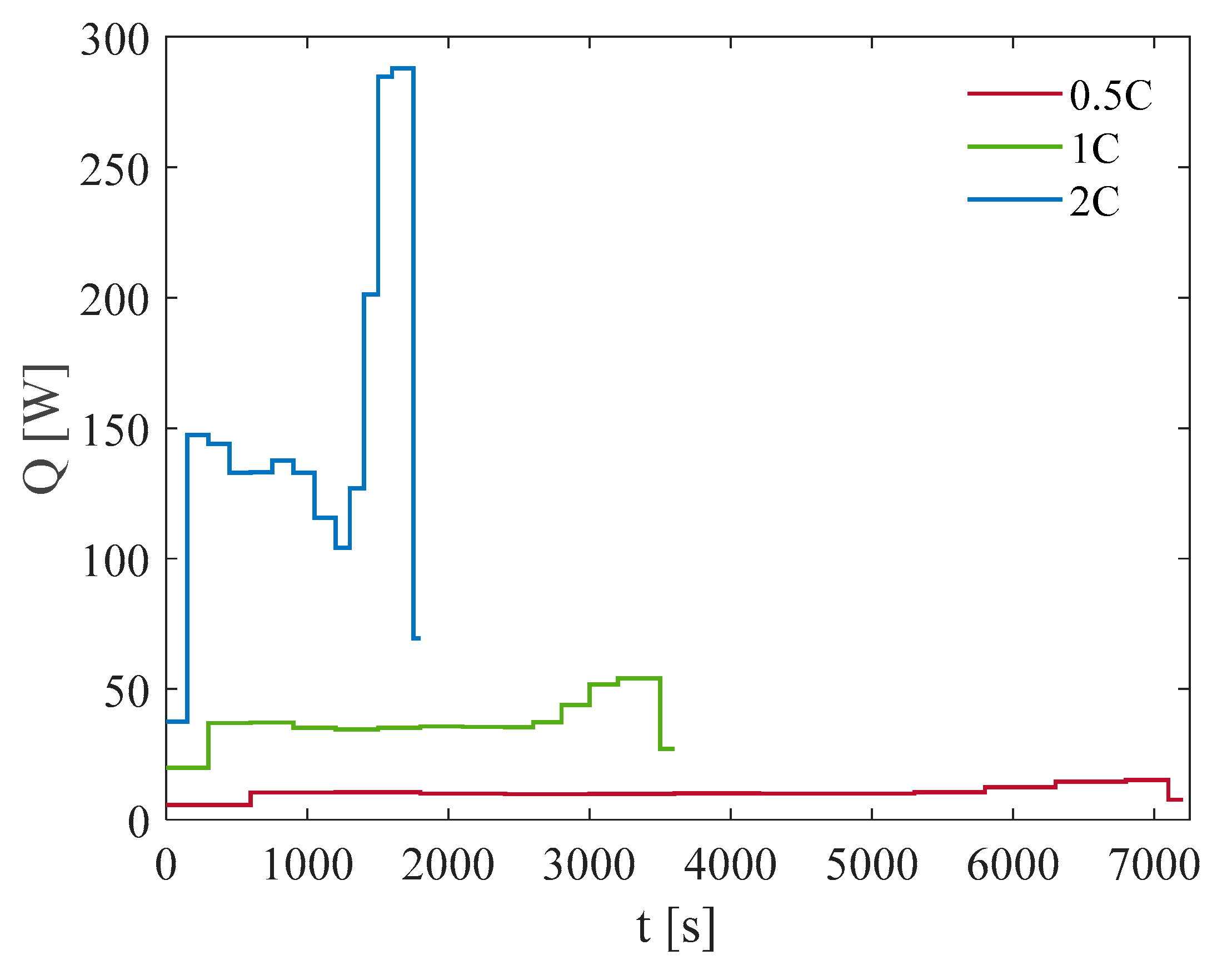
In this formula, I represents the discharge current, V is the operating voltage, T is the battery surface temperature in Kelvin, Uoc is the open-circuit voltage, and ∂Uoc/∂T denotes the entropic heat coefficient. The calculated thermal output for the battery pack under different conditions is presented in Figure 3, which shows the discharge profiles at varying C-rates.

3.1. Test at Ambient Temperature of 5 °C

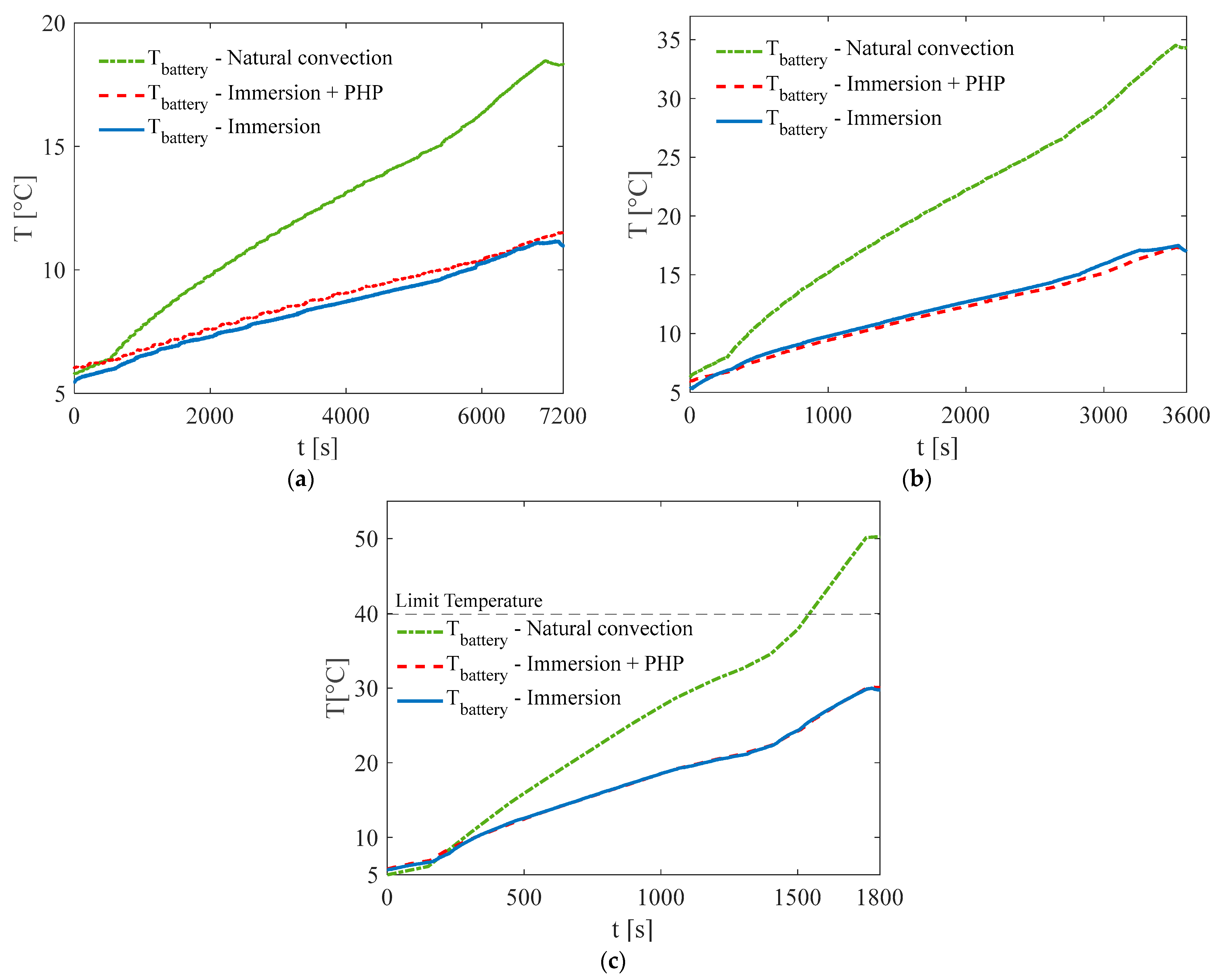
The primary objective of the Battery Thermal Management System (BTMS) is to maintain battery temperatures below 40 °C, thereby preventing malfunctions or potential thermal runaway events. Consequently, one of the key performance indicators of a cooling system is the peak temperature reached by the battery during operation. In tests performed at an ambient temperature of 5 °C (see Figure 4), the battery pack stayed below 40 °C with all three cooling methods during discharge rates of 0.5C and 1C. However, during the 2C discharge with natural convection cooling, the battery temperature rose to 50.3 °C. This is above the recommended 20–40 °C range for electric batteries, showing that natural convection alone is not enough to keep the battery cool under these conditions.
In contrast, direct immersion cooling significantly reduced temperature rise, keeping it within acceptable limits. However, there was no temperature difference between the configuration using the PHP and the one without it. Both setups began at the same initial temperature and reached a maximum of 30 °C by the end of the 2C discharge test. This shows that the dielectric fluid was able to manage the heat well, mainly because of its high thermal capacity and natural convection through the container walls. Importantly, the temperature of Opteon SF33 stayed below its boiling point of about 33 °C, so there was little to no vapor forming. This means the PHP had little effect on heat transfer during the tests at 5 °C and did not noticeably change the fluid’s behavior or the battery’s temperature.
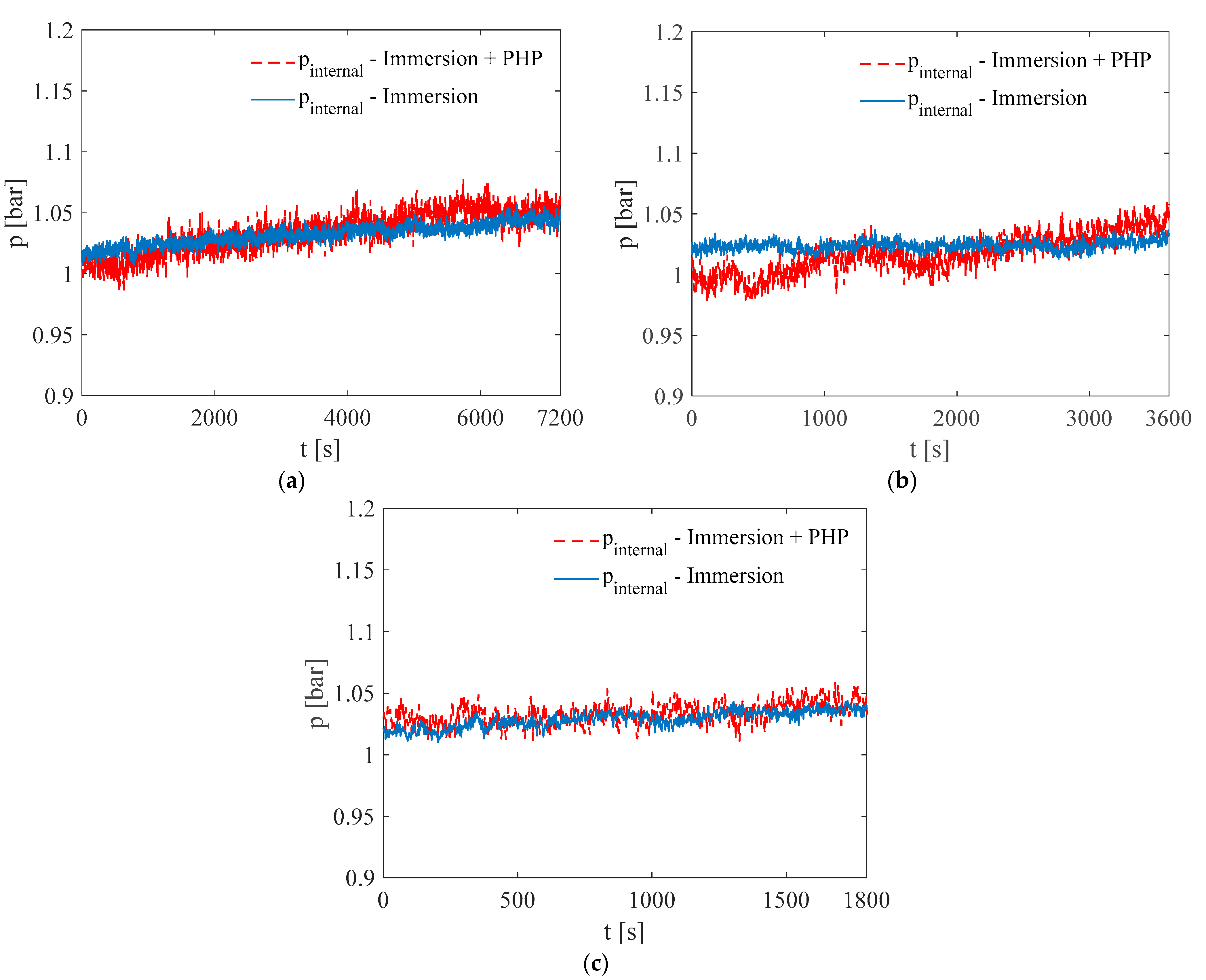
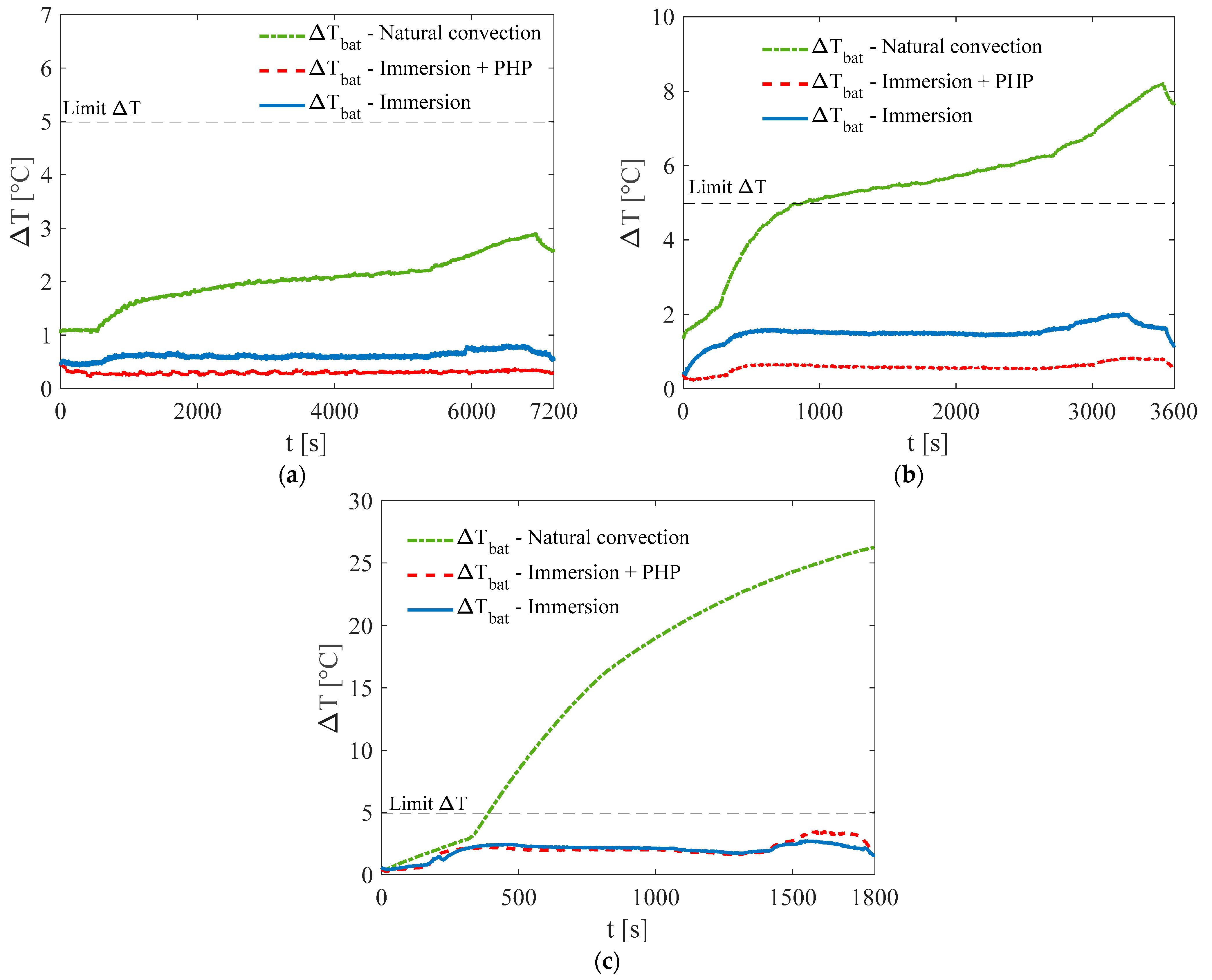
As illustrated in Figure 5, internal pressure within the enclosure remained stable in both configurations and across all discharge C-rates using Opteon SF33, since boiling did not occur. While the PHP configuration exhibited slightly lower pressure readings—about 0.01 bar lower—this difference is negligible and does not affect the overall analysis. These results show that the dielectric fluid works appropriately, and the system remains thermally stable under the tested conditions. Another important factor for evaluating BTMS is the temperature difference inside the battery (ΔT). It is generally recommended to keep ΔT below 5 °C, because higher differences can reduce performance or even cause damage. During the tests, natural convection did not meet this standard, with ΔT reaching 8.2 °C and 26.2 °C in the later stages of the 1C and 2C discharge tests, respectively. In comparison, full immersion in the dielectric fluid significantly enhanced thermal uniformity, as shown in Figure 6. In both tested configurations, temperature variation remained within acceptable limits under all discharge conditions. A consistent ΔT of approximately 2 °C was recorded, enabled by the dielectric fluid’s direct and uniform contact with all battery surfaces.
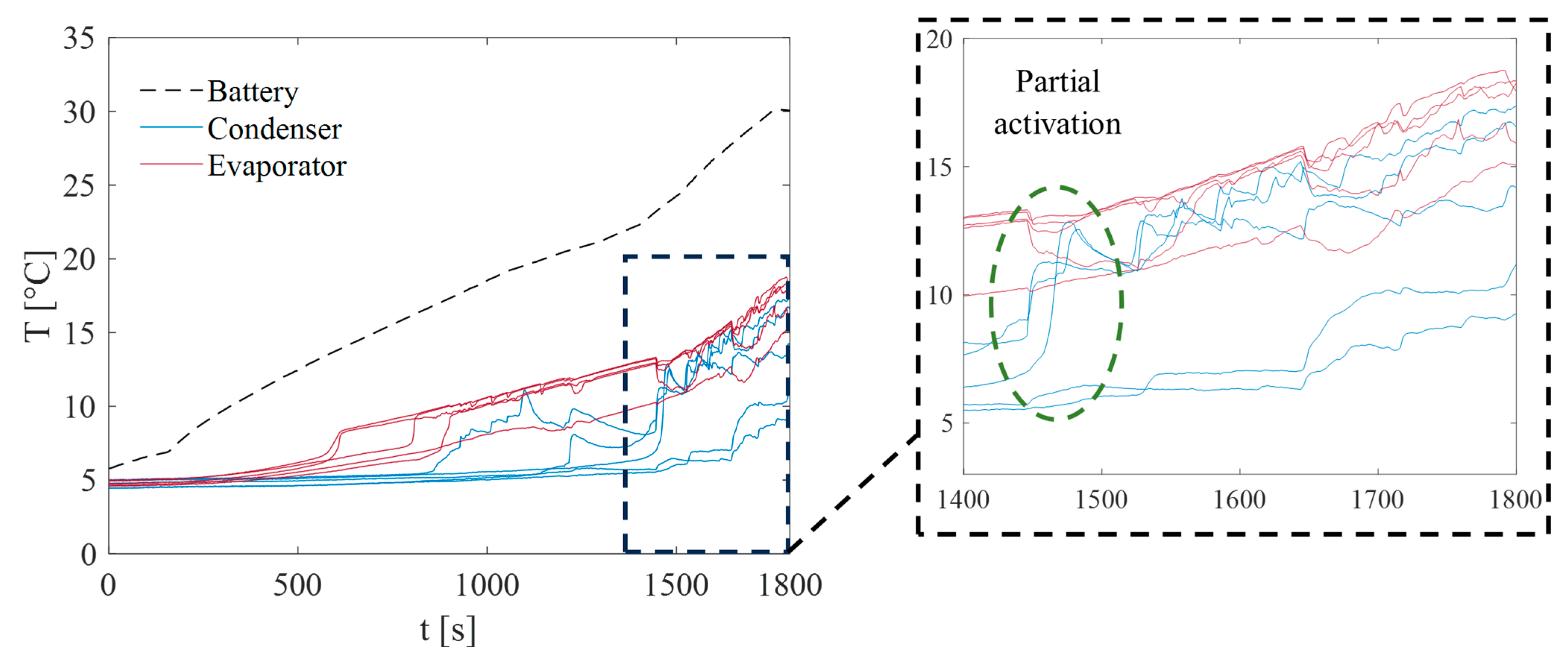
Notably, there were no significant differences in performance between the setup using the PHP and the one using only Opteon SF33. This supports the earlier conclusion that the PHP had little impact on heat transfer under these test conditions. The device activation and the presence of oscillatory fluid motion within the PHP can be inferred from the temperature profiles of the evaporator and condenser sections. Specifically, temperature oscillations in both regions are indicative of dynamic two-phase flow, driven by the cyclic formation and collapse of vapor bubbles and liquid slugs. Additionally, a decreasing temperature gradient—where the condenser temperature approaches that of the evaporator—suggests enhanced thermal coupling due to active fluid circulation. As shown in Figure 7—reporting the temperature profiles during the more demanding 2C discharge test at 5 °C—the temperature trends in the condenser and evaporator sections of the PHP indicate only partial activation of the two-phase device, suggesting that the internal oscillatory motion of the working fluid was limited. This partial activation implies that the thermal performance was constrained by insufficient vapor bubble nucleation and liquid slug movement, which are essential for efficient heat transfer in a fully operational PHP. The factor that the boiling point of Opteon SF33 has not been reached, and the consequent limited production of its vapor may have hindered the development of sustained pulsations, resulting in less effective thermal transport between the evaporator and condenser. This limited activation results in a not significant contribution to overall heat dissipation. Consequently, in the other two less demanding discharge conditions, no PHP activity was observed, confirming a complete lack of activation.
The experimental results at 5 °C clearly show that natural convection alone cannot meet the battery’s cooling needs, as it fails to keep key factors like peak cell temperature and temperature uniformity (ΔT) within safe limits. On the other hand, immersion cooling is a very effective passive method, significantly reducing temperature differences and keeping the whole battery pack within the desired range. This approach provides reliable temperature control without using active parts, making it ideal for compact or energy-saving designs. However, it still requires an additional system to transfer heat from the cooling tank to the outside environment, as in the current configuration, this is only achieved through natural convection via the case walls. Adding the PHP to the system did not lead to noticeable improvements in cooling for the present test conditions. Although it introduces complexity and utilizes a two-phase heat transfer method designed to enhance cooling, the PHP had little to no effect under these test conditions. This suggests that the PHP was only partially active or did not add much because immersion cooling was already handling most of the heat at this temperature.

3.2. Test at Ambient Temperature of 20 °C

It is evident that an ambient temperature of 20 °C poses a greater challenge for the cooling of the battery pack compared to tests conducted at 5 °C. Under natural convection conditions, only during a 0.5C discharge rate did the battery temperature remain below 40 °C. At a 1C discharge rate, the temperature increased significantly, reaching a peak value of 42.6 °C. These findings led to the decision not to proceed with the 2C discharge test under the new environmental conditions, due to concerns about thermal safety. The results clearly indicate that natural convection is inadequate for managing the thermal load of the battery pack at higher power levels. A significant improvement in thermal management was achieved through the immersion of the battery pack in the low-boiling dielectric fluid, Opteon SF33. Also, for ambient temperature equal to 20 °C at both 0.5C and 1C discharge rates, the favorable thermal properties and high thermal capacity of the fluid effectively limited the temperature rise, ensuring that thermal requirements were not exceeded, as illustrated in Figure 8. The maximum temperatures recorded were 25.1 °C at 0.5C and 31.3 °C at 1C, remaining significantly below critical safety thresholds.
However, it is noteworthy that, as observed in previous tests conducted at an ambient temperature of 5 °C, when the fluid does not reach its boiling point, the integration of a PHP with the immersion cooling system does not result in a noticeable difference in the battery’s thermal behavior. Under low power input conditions, the heat generated by the battery is primarily absorbed as sensible heat by the liquid phase of Opteon SF33.
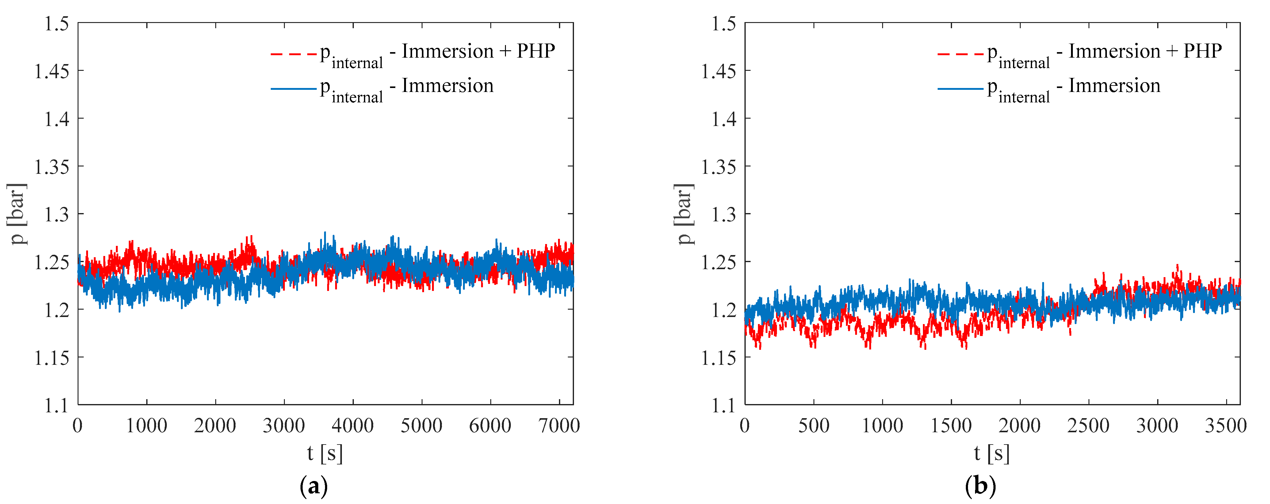
Since the boiling point is not reached, vapor generation is minimal, thereby limiting the activation of the PHP. Given that the primary function of the integrated PHP is to enhance heat transfer through the rapid condensation of the dielectric vapor, its contribution under these specific conditions remains negligible. Additionally, under these operating conditions, the internal pressure within the battery case remains relatively stable throughout the tests, around 1.2 bar during both 0.5C and 1C tests as shown in Figure 9.
This stability is attributed to the lower fluid temperatures, which stay significantly below the boiling point of Opteon SF33, resulting in minimal vapor production and, consequently, no significant increase in internal pressure. Under these test conditions, natural convection also fails to maintain uniform temperatures within the battery pack.
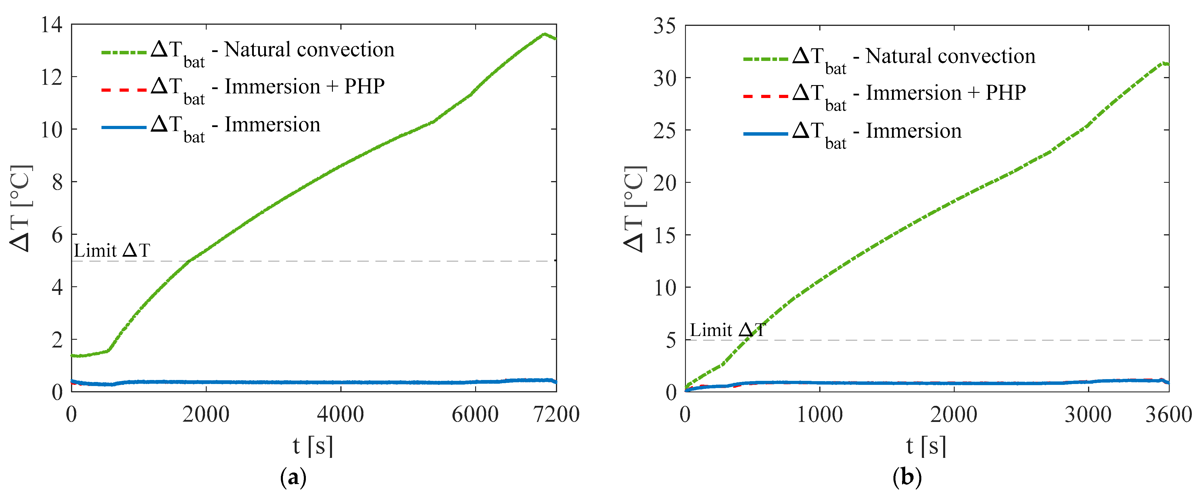
As shown in Figure 10, the temperature difference reaches highs of 13.6 °C at 0.5C and 31.4 °C at 1C, both well above the recommended limit of 5 °C. In contrast, immersion cooling greatly improves temperature uniformity. During the 0.5C test, the temperature difference across the battery pack stayed below 0.5 °C, and at 1C, it remained within 1.2 °C. This proves how well the dielectric fluid absorbs and spreads heat evenly from the cells. These results show that immersion cooling not only lowers the overall battery temperature but also reduces hot spots and thermal stress among cells. However, consistent with earlier findings, there was no noticeable difference in performance between using immersion cooling alone and combining it with the PHP under these test conditions.
To better understand how the battery pack behaves under tougher and more critical conditions, tests were performed to simulate higher heat generation and increased thermal risk. For this purpose, the power input was raised by running tests at a 2C discharge rate, which puts much more thermal stress on the system. Also, these experiments were performed in a controlled environment with the ambient temperature maintained at 20 °C. The tests were conducted for direct immersion cooling alone, and direct immersion cooling combined with a PHP.
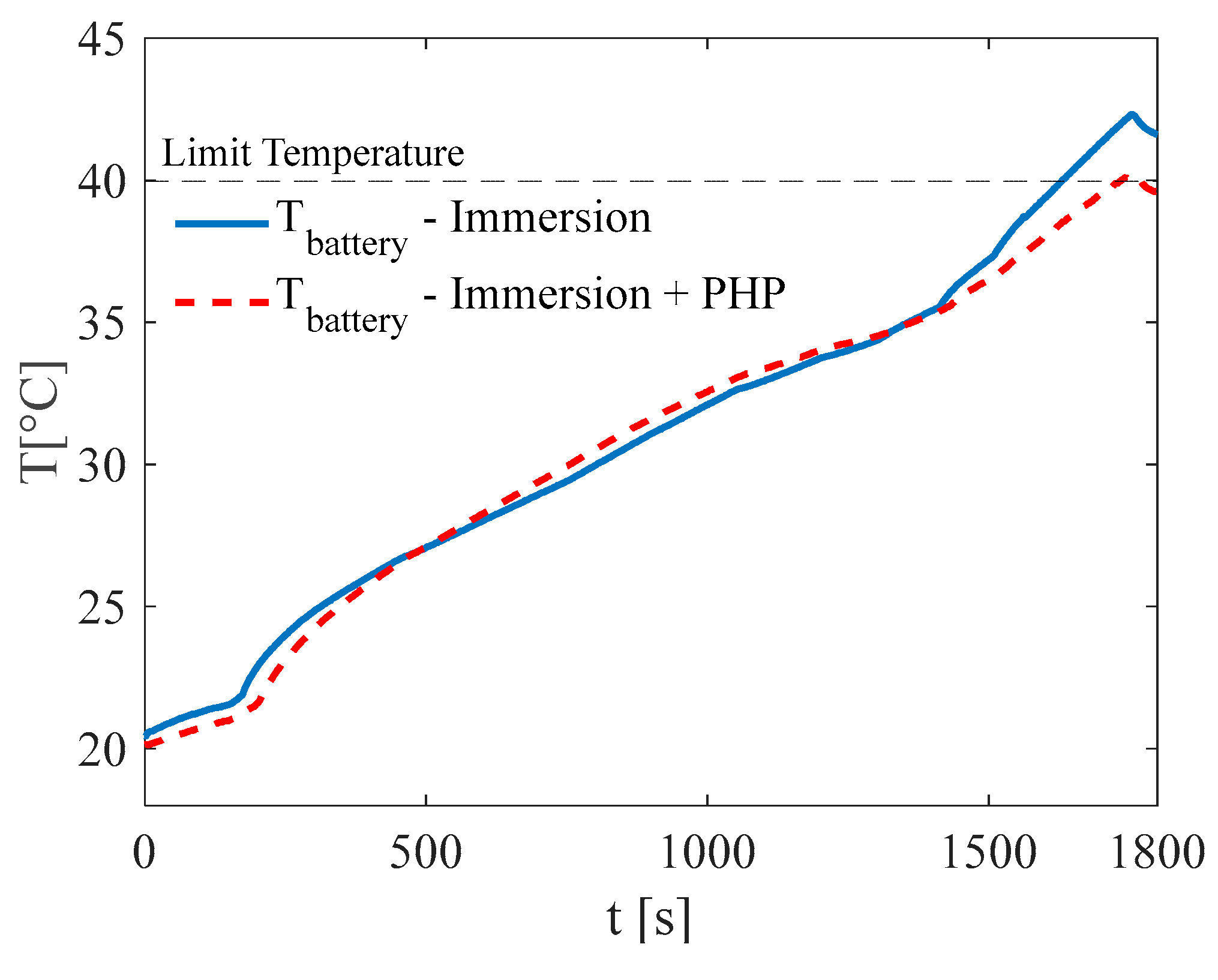
The temperature evolution of the battery during 2C discharge is shown in Figure 11, revealing several noteworthy trends. During the early stage of the discharge cycle (0–1200 s), the thermal behavior of the two configurations is nearly identical. In this initial period, the heat generated by the battery is absorbed primarily as sensible heat by the liquid phase of the dielectric fluid, Opteon SF33. Since the temperature stays below the fluid’s boiling point (around 33 °C), there is little to no vaporization, and the PHP stays inactive. Because of this, both setups show a similar rate of temperature increase. However, once the discharge continues and the battery temperature goes above the boiling point of Opteon SF33, their thermal behavior starts to differ noticeably. From about 1200 s onward, the system using only immersion cooling shows a continued rise in battery temperature, reaching a peak of around 42 °C.
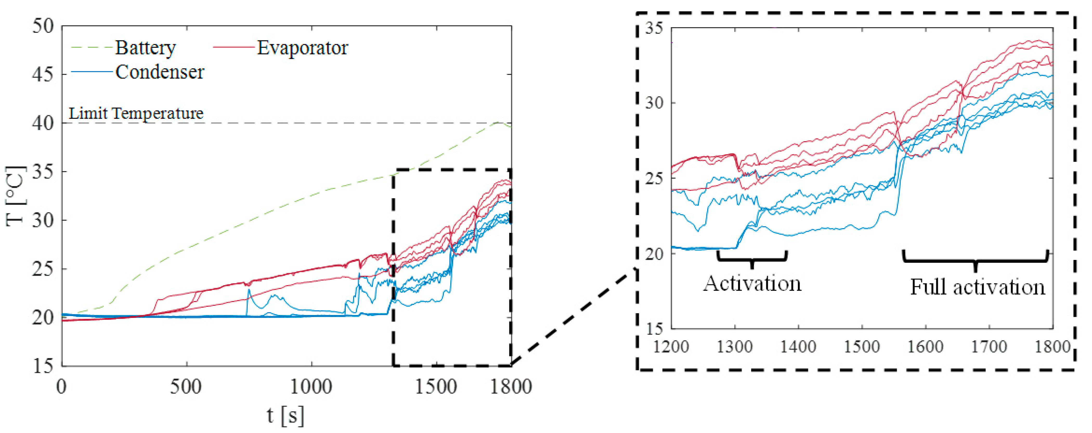
In contrast, direct immersion combined with PHP configuration displays a more controlled thermal response, with the battery temperature remaining below the threshold for most of the test, except for a few seconds, in which it reaches 40.1 °C. This difference can be attributed to the activation of the PHP. The onset of boiling plays a pivotal role in this activation process. As shown in the evaporator and temperature profiles depicted in Figure 12, three distinct operational phases of the PHP can be identified. Initially, from the start of the test up to approximately 1300 s, the PHP remains in an inactive state with no pulsations observable in the evaporator and condenser temperatures and with a significant and stable gradient between the temperature of these two sections. During this period, the dielectric immersion fluid has not yet reached its boiling point, and thus only a small amount of vapor was generated, which prevents activation of the second two-phase device for battery thermal control, the PHP.
However, around the 1300 s, as the fluid reaches its boiling temperature, the generation of vapor increases markedly. This triggers the activation of the PHP, which benefits from the latent heat of the condensing Opteon vapor on the walls of its evaporator section: in the final 300 s of the test, the PHP demonstrates full activation. During this phase, the device exhibits stable and continuous pulsating activity, which further enhances heat transfer efficiency. Moreover, a narrowing temperature difference between the condenser and the evaporator is noticeable. It indicates improved thermal interaction resulting from active movement of the working fluid inside the PHP. The activation of the PHP—operating in the Opteon SF33 vapor phase region—enables the rapid condensation of the Opteon vapor. This cyclical phase change, wherein vapor is continuously condensed back into the liquid phase, significantly boosts the overall heat transfer capability of the system.
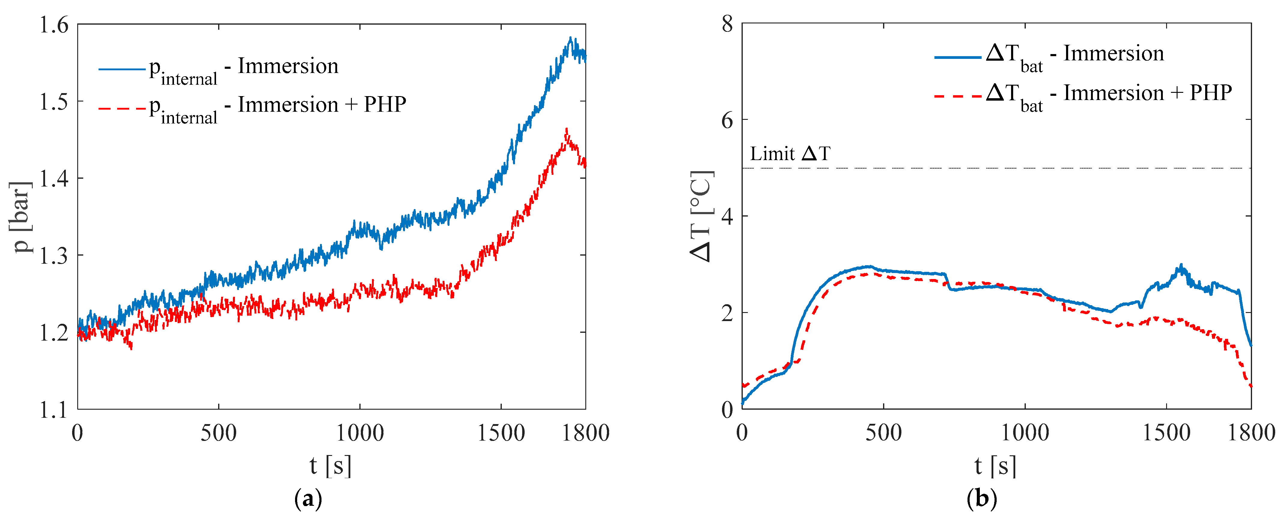
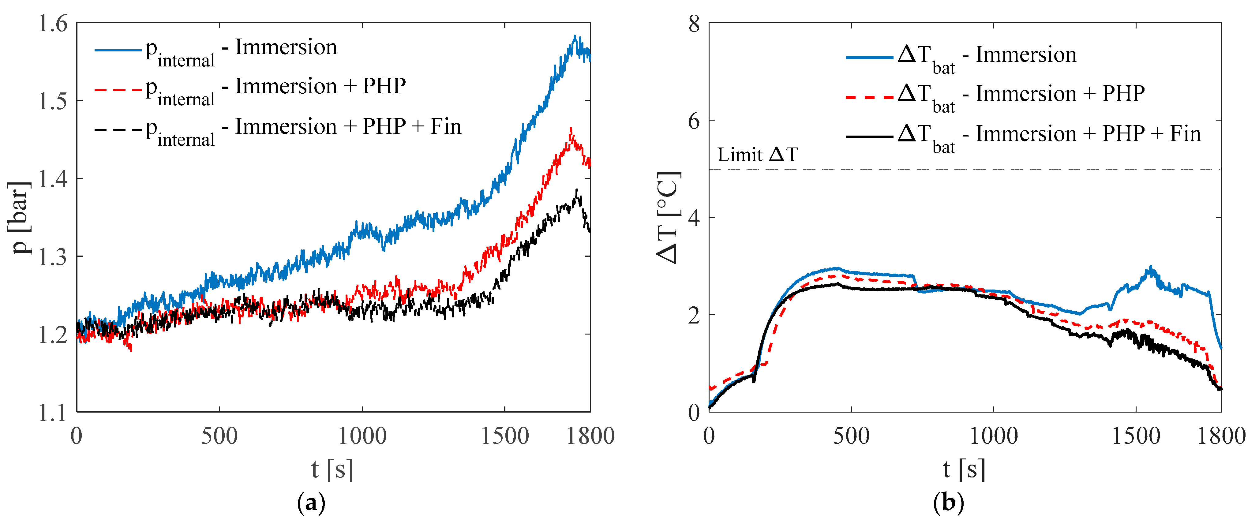
Additionally, the PHP helps control the internal pressure inside the enclosure by efficiently recondensing the working fluid. When the fluid vaporizes, pressure rises because of the vapor build-up. But in the system with the PHP, this pressure increase is reduced since the vapor is constantly condensed back into liquid form. As shown in Figure 13a, the pressure in the PHP-assisted configuration remains more stable and controlled compared to the immersion-only setup. This pressure stability is crucial not only for maintaining consistent thermal performance but also for enhancing system safety by reducing the risk of overpressure conditions and potential mechanical failure. Another key factor to consider during the 2C discharge test is the temperature difference within the battery pack, as it affects how evenly heat is spread—and this impacts the battery’s performance, aging, and safety. During the first part of the test (0–1000 s), both cooling setups—immersion alone and immersion with PHP—show a similar rise in temperature difference, reaching about 2.98 °C before settling around 2.5 °C.
As the test continues and the battery temperature nears the boiling point of the fluid, the two systems behave differently. In the immersion-only setup, the temperature difference keeps increasing, peaking around 3.0 °C. This suggests that heat is not being uniformly dissipated across the battery pack, and localized hot spots may begin to form as vaporization increases but lacks efficient management. On the other hand, the system with the PHP performs better. Once the fluid starts boiling and the PHP activates, the temperature difference stops rising and steadily drops. In the last 600 s, it falls below 2.0 °C, showing a more even temperature across the battery cells. This better thermal balance is thanks to the PHP’s improved heat transfer, which quickly condenses Opteon vapor, helping spread heat and prevent local overheating. The PHP functions as a thermal equalizer, redistributing excess heat away from hotter regions and thereby maintaining more consistent temperatures throughout the battery pack. From this analysis, it can be concluded that both immersion cooling and the proposed BTMS can maintain the temperature gradient within the battery pack below the critical threshold recommended in the literature, typically cited around 5 °C to avoid performance degradation; however, the integration of a PHP slightly improves thermal uniformity.
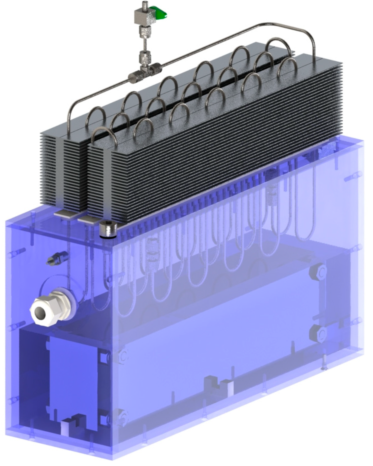
The demanding conditions observed during the last discharge test at 2C rate, where battery reached a peak temperature of 40.1 °C, suggest improving the performance of the BTMS proposed by adding an extended surface to the condenser section of the PHP. In fact, the limited heat exchange area in the condenser coupled with low heat transfer coefficient values related to the cooling mechanism by natural convection with ambient air represents the main bottleneck in heat dissipation during the discharge process. As illustrated in Figure 14, a finned surface was implemented in contact with the branches of the PHP to enhance heat transfer in the condenser section.
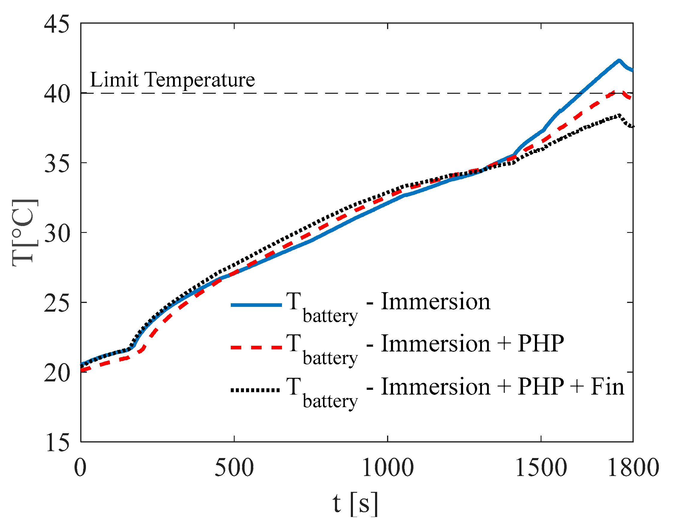
This configuration was tested under the previously described conditions: a 2C discharge rate at an ambient temperature of 20 °C. The results obtained were compared with those from the two earlier configurations—immersion cooling and immersion cooling combined with a PHP without fins. The introduction of an extended surface clearly enhances the battery’s thermal management. As shown in Figure 15, during the last 600 s, when the phase-change process of Opteon SF33 begins and the PHP actively contributes to heat dissipation, the temperature rise is significantly reduced compared to the other two configurations. As a result, the battery temperature remains significantly below the imposed limit of 40 °C.
This upgrade also improves pressure control by increasing the rate of recondensation compared to the original configuration. This leads to a slower pressure rise and a lower peak pressure, as shown in Figure 16a. Regarding internal temperature variations, the results are comparable to previous configurations. A slight improvement is observed relative to the other two setups, although it is not particularly significant. Temperature uniformity is consistently maintained, with a maximum difference of 2.8 °C—consistently below the recommended limit for Li-ion batteries, as shown in Figure 16b.
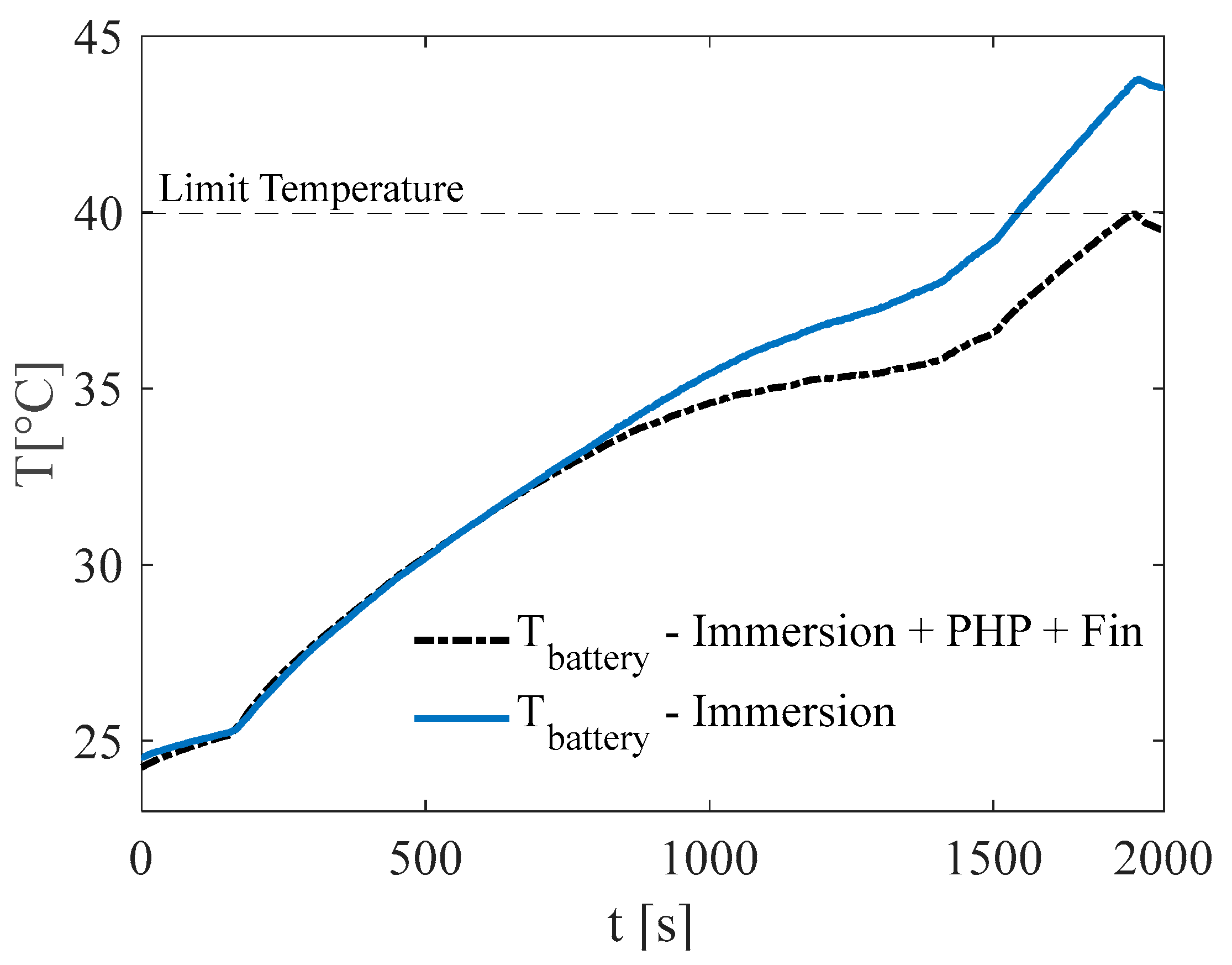
To better assess the system’s limits in handling heat, tests were run under tougher conditions. A 2C discharge test was performed at 25 °C ambient temperature, comparing two setups: direct immersion cooling by itself, and direct immersion cooling paired with a finned pulsating heat pipe. The analysis of the battery’s maximum temperature during the discharge test revealed notable differences between the two setups, as shown in Figure 17. Compared to previous tests at the same power level, the distinction between the two configurations is more pronounced, primarily because the phase change process begins around the middle of the test rather than toward the final stage.
This results in the PHP playing a more significant role in heat dissipation. In the setup combining direct immersion cooling with the PHP, the temperature levels off around 34 °C during the early evaporation phase (between 1100 and 1400 s). On the other hand, the system using only direct immersion cooling keeps warming up, reaching a peak of 43.8 °C—going beyond the safe limit of 40 °C. In the last 400 s, even the combined system sees a temperature rise because of the higher power being used. However, it successfully keeps the battery temperature below the safety threshold throughout the entire test duration.
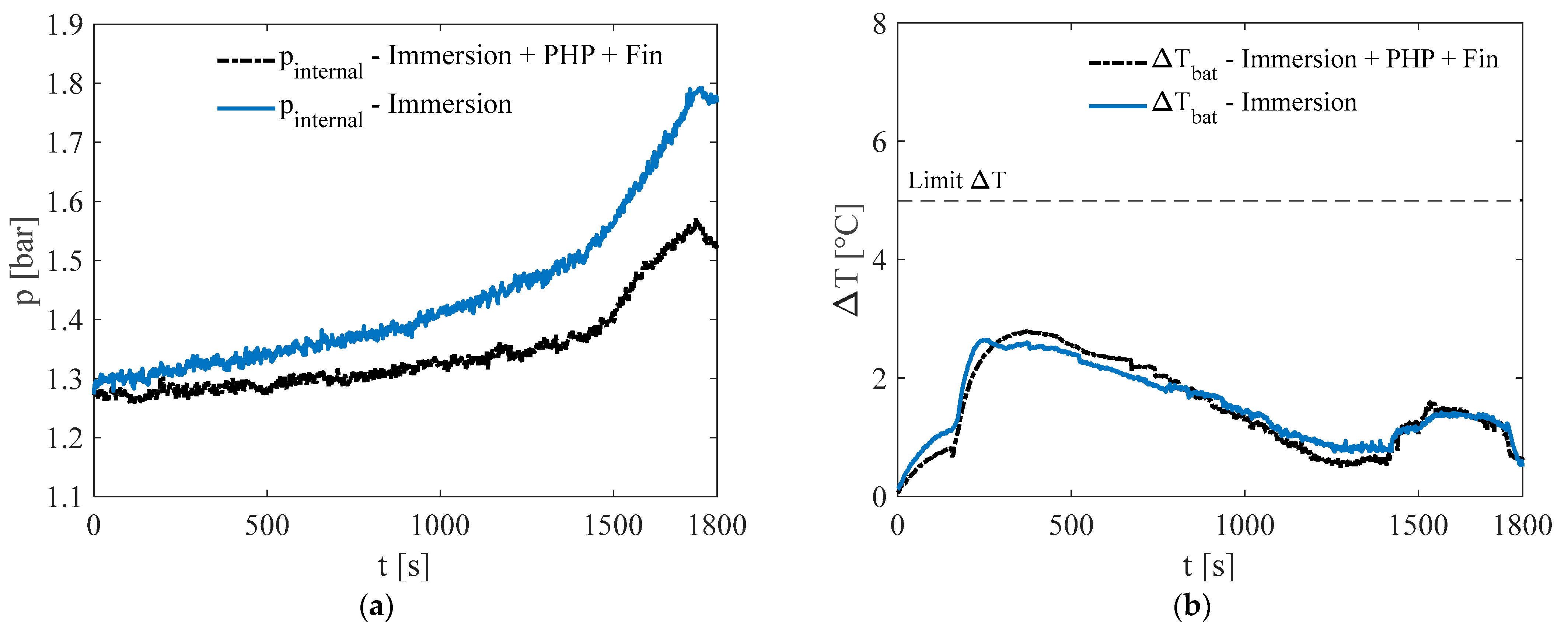
The results in terms of internal pressure and temperature difference across the battery pack, as shown in Figure 18, support the observations made during the 2C discharge test at 20 °C. Adding the PHP helps reduce the pressure rise, with a peak of about 1.5 bar, compared to 1.8 bar in the direct immersion cooling setup without PHP. While the PHP with extended surface area does not significantly improve temperature uniformity—as shown in Figure 18b—it still maintains strong thermal performance in both setups. In every case, the maximum temperature difference across the battery pack stays below 3 °C throughout the test.
In conclusion, our findings highlight the effectiveness of the proposed BTMS, as illustrated by Table 1, which resumes the main results. While direct immersion cooling alone provides substantial thermal buffering under low to moderate discharge rates, its efficiency significantly diminishes under high-load conditions. As power demands increase, the system struggles to dissipate heat quickly enough, leading to elevated battery temperatures and potential performance degradation. The insertion of the PHP provides a complementary, passive thermal regulation strategy that dynamically responds to these thermal challenges. By leveraging the phase change in the working fluid, the PHP becomes active during critical thermal events—such as power surges or elevated ambient temperatures—where conventional immersion cooling alone becomes insufficient.
This dual two-phase cooling system helps lower temperature spikes, keeps internal pressure more stable, and greatly improves the system’s safety and reliability. These benefits are especially important for high-performance batteries used in tough environments like electric vehicles, aerospace, and large-scale energy storage.

4. Conclusions

This study tackles the challenging issue of managing heat in lithium-ion batteries for electric vehicles, highlighting the need to keep battery temperatures between 20 °C and 40 °C while minimizing temperature differences between cells. To address this, a dual two-phase cooling system was developed using Opteon SF33, a low-boiling-point dielectric fluid, for immersion cooling. A PHP was also added to further improve temperature control. The test results clearly show that this BTMS is effective. It consistently kept battery temperatures within the ideal range under all tested conditions. Besides good overall temperature control, the system maintained excellent temperature uniformity across the battery pack. Thanks to full immersion and the phase-change properties of the fluid, the temperature differences stayed below the recommended 5 °C limit, which helps ensure consistent performance and reduces thermal stress on the cells. The phase-change process helped lower peak temperatures and stabilize the battery’s thermal behavior. Meanwhile, the PHP played an important role in managing internal pressure inside the sealed enclosure. By speeding up the condensation of vapor back into liquid, the PHP reduced pressure spikes that usually happen during boiling. This lowers the risk of mechanical strain or failure and supports safer, more reliable operation—something especially important in compact or closed systems where pressure build-up can be dangerous. Overall, adding the PHP not only boosts thermal performance but also improves safety and reliability, marking an important step forward in cooling high-performance battery systems. The study’s findings provide a strong foundation for future work. The next phase of this research will involve testing the system with an actual lithium-ion battery module, rather than the current aluminum surrogate, to better capture its real-world performance. A defined strategy for future development can be outlined as follows:
-
Performance optimization: The PHP design will be refined, with particular attention to increasing the heat exchange area in the evaporator and condenser sections to improve handling of higher discharge rates and operation in warmer environments.
-
System integration: Efforts will focus on making the system more compact and efficient by reducing the size of enclosure and optimizing fluid volume. This step is especially important for space-constrained applications such as electric vehicles.
-
Hybridization for extreme conditions: In the engineering phase of product development, active elements can be incorporated into the condenser section of the PHP. This hybrid approach would extend the applicability of the system to rare but extreme high-temperature scenarios. Since such conditions are expected to occur only occasionally and for limited durations, the required active components would remain simplified and significantly downsized compared to conventional cooling systems.

Author Contributions

Conceptualization, L.C. and F.B.; methodology, L.C.; software, F.S.; validation F.S. and L.C.; formal analysis, L.C. and F.B.; investigation, F.S. and L.C.; resources, L.C.; data curation, F.S.; writing—original draft preparation, L.C. and F.S.; writing—review and editing, F.B.; visualization, F.S.; supervision, L.C. and F.B.; project administration, L.C.; funding acquisition, L.C. All authors have read and agreed to the published version of the manuscript.

Funding

This research was granted by PNRR—M4C2—I1.1—Avviso MUR 104 del 02-02-2022—“PRIN 2022—D.D. 1401 del 18-09-2024—scorrimento”—Settore ERC PE8-Titolo Progetto: ELECTRA—Enhanced Liquid cooling for ElectriC Traction systems in Recreational Aviation—Codice Progetto 2022BTSF52—Codice CUP D53C24003970006—finanziato dall’Unione europea—NextGenerationEU and by National Recovery and Resilience Plan (NRRP) Mission 4 Component 2 Investment 1.5—Call for tender No. 3277 of 30/12/2021 of Italian Ministry of University and Research funded by the European Un-ion—NextGenerationEU (Award Number: Project code ECS00000033, Concession Decree No. 1052 of 23/06/2022 adopted by the Italian Ministry of, CUP D93C22000460001, “Eco-system for Sustainable Transition in Emilia-Romagna” (Ecosister).

Data Availability Statement

The data that support the findings of this study are available from the corresponding author, L.C., upon reasonable request.

Conflicts of Interest

The authors declare no conflicts of interest.

References

  1. Keiner, D.; Ram, M.; Barbosa, L.D.S.N.S.; Bogdanov, D.; Breyer, C. Cost Optimal Self-Consumption of PV Prosumers with Stationary Batteries, Heat Pumps, Thermal Energy Storage and Electric Vehicles across theWorld up to 2050. Sol. Energy 2019, 185, 406–423. [Google Scholar] [CrossRef]
  2. Mohammadi, F.; Saif, M. A comprehensive overview of electric vehicle batteries market. E-Prime Adv. Electr. Eng. Electron. Energy 2023, 3, 100127. [Google Scholar] [CrossRef]
  3. Shi, C.; Wang, T.; Liao, X.; Qie, B.; Yang, P.; Chen, M.; Wang, X.; Srinivasan, A.; Cheng, Q.; Ye, Q.; et al. Accordion-like stretchable Li-ion batteries with high energy density. Energy Storage Mater. 2019, 17, 136–142. [Google Scholar] [CrossRef]
  4. Kim, T.; Song, W.; Son, D.-Y.; Ono, L.K.; Qi, Y. Lithium-ion batteries: Outlook on present, future, and hybridized technologies. J. Mater. Chem. A 2019, 7, 2942–2964. [Google Scholar] [CrossRef]
  5. Arun, V.; Kannan, R.; Ramesh, S.; Vijayakumar, M.; Raghavendran, P.S.; Siva Ramkumar, M.; Anbarasu, P.; Sundramurthy, V.P. Review on Li-Ion Battery vs Nickel Metal Hydride Battery in EV. Adv. Mater. Sci. Eng. 2022, 2022, 7910072. [Google Scholar] [CrossRef]
  6. Gayathri, A.; Manimegalai, V.; Krishnakumar, P. Challenging Issues and Solutions on Battery Thermal Management for Electric Vehicles. In Electrical and Electronic Devices, Circuits, and Materials: Technological Challenges and Solutions; Scrivener Publishing LLC: Beverly, MA, USA, 2021; pp. 535–553. [Google Scholar]
  7. Lyu, Y.; Siddique, A.R.M.; Majid, S.H.; Biglarbegian, M.; Gadsden, S.A.; Mahmud, S. Electric vehicle battery thermal management system with thermoelectric cooling. Energy Rep. 2019, 5, 822–827. [Google Scholar] [CrossRef]
  8. Al-Zareer, M.; Dincer, I.; Rosen, M.A. A novel phase change based cooling system for prismatic lithium-ion batteries. Int. J. Refrig. 2018, 86, 203–217. [Google Scholar] [CrossRef]
  9. Zhang, X.; Li, Z.; Luo, L.; Fan, Y.; Du, Z. A review on thermal management of lithium-ion batteries for electric vehicles. Energy 2022, 238, 121652. [Google Scholar] [CrossRef]
  10. Ma, S.; Jiang, M.; Tao, P.; Song, C.; Wu, J.; Wang, J.; Deng, T.; Shang, W. Temperature effect and thermal impact in lithium-ion batteries: A review. Prog. Nat. Sci. Mater. Int. 2018, 28, 653–666. [Google Scholar] [CrossRef]
  11. Lu, Z.; Yu, X.L.; Wei, L.C.; Cao, F.; Zhang, L.Y.; Meng, X.Z.; Jin, L.W. A comprehensive experimental study on temperature-dependent performance of lithium-ion battery. Appl. Therm. Eng. 2019, 158, 113800. [Google Scholar] [CrossRef]
  12. Deng, Y.; Feng, C.; E, J.; Zhu, H.; Chen, J.; Wen, M.; Yin, H. Effects of different coolants and cooling strategies on the cooling performance of the power lithium-ion battery system: A review. Appl. Therm. Eng. 2018, 142, 10–29. [Google Scholar] [CrossRef]
  13. Ghalkhani, M.; Habibi, S. Review of the Li-Ion Battery, Thermal Management, and AI-Based Battery Management System for EV Application. Energies 2023, 16, 185. [Google Scholar] [CrossRef]
  14. Lu, L.; Han, X.; Li, J.; Hua, J.; Ouyang, M. A review on the key issues for lithium-ion battery management in electric vehicles. J. Power Sources 2013, 226, 272–288. [Google Scholar] [CrossRef]
  15. Feng, X.; Xu, C.; He, X.; Wang, L.; Zhang, G.; Ouyang, M. Mechanisms for the evolution of cell variations within a LiNixCoyMnzO2/graphite lithium-ion battery pack caused by temperature non-uniformity. J. Clean. Prod. 2018, 205, 447–462. [Google Scholar] [CrossRef]
  16. Wu, W.; Wang, S.; Wu, W.; Chen, K.; Hong, S.; Lai, Y. A critical review of battery thermal performance and liquid based battery thermal management. Energy Convers. Manag. 2019, 182, 262–281. [Google Scholar] [CrossRef]
  17. Akinlabi, A.A.H.; Solyali, D. Configuration, design, and optimization of air-cooled battery thermal management system for electric vehicles: A review. Renew. Sustain. Energy Rev. 2020, 125, 109815. [Google Scholar] [CrossRef]
  18. Wang, M.; Teng, S.; Xi, H.; Li, Y. Cooling performance optimization of air-cooled battery thermal management system. Appl. Therm. Eng. 2021, 195, 117242. [Google Scholar] [CrossRef]
  19. Wang, X.; Liu, S.; Zhang, Y.; Lv, S.; Ni, H.; Deng, Y.; Yuan, Y. A review of the power battery thermal management system with different cooling, heating and coupling system. Energies 2022, 15, 1963. [Google Scholar] [CrossRef]
  20. An, Z.; Jia, L.; Li, X.; Ding, Y. Experimental investigation on lithium-ion battery thermal management based on flow boiling in minichannel. Appl. Therm. Eng. 2017, 117, 534–543. [Google Scholar] [CrossRef]
  21. Wang, Y.; Li, C.; Wen, X.; Cai, W.; Jiang, Y.; Wen, C.; Wang, Y.; Hu, L.; Yu, H.; Zhu, H.; et al. Experimental studies on two-phase immersion liquid cooling for Li-ion battery thermal management. J. Energy Storage 2023, 72, 108748. [Google Scholar] [CrossRef]
  22. Hirano, H.; Tajima, T.; Hasegawa, T.; Sekiguchi, T.; Uchino, M. Boiling liquid battery cooling for electric vehicle. In Proceedings of the 14th ITEC Asia-Pacific, Chiang Mai, Thailand, 28 November–1 December 2023. [Google Scholar]
  23. Roe, C.; Feng, X.; White, G.; Li, R.; Wang, H.; Rui, X.; Li, C.; Zhang, F.; Null, V.; Parkes, M.; et al. Immersion cooling for lithium-ion batteries—A review. J. Power Sources 2022, 525, 231094. [Google Scholar] [CrossRef]
  24. Saleem, A.; Iqbal, R.; Hussain, A.; Javed, M.S.; Ashfaq, M.Z.; Imran, M.; Hussain, M.M.; Akbar, A.R.; Shen, J.; Majeed, M.K. Recent advances and perspectives in carbon-based fillers reinforced Si3N4 composite for high power electronic devices. Ceram. Int. 2022, 48, 13401–13419. [Google Scholar] [CrossRef]
  25. Jalees, S.; Hussain, A.; Iqbal, R.; Raza, W.; Ahmad, A.; Saleem, A.; Majeed, M.K.; Faheem, M.; Ahmad, N.; Rehman, L.N.U.; et al. Functional PBI membrane based on polyimide covalent organic framework for durable lithium metal battery. J. Energy Storage 2024, 101, 113985. [Google Scholar] [CrossRef]
  26. Luo, J.; Zou, D.; Wang, Y.; Wang, S.; Huang, L. Battery thermal management systems (BTMs) based on phase change material (PCM): A comprehensive review. Chem. Eng. J. 2022, 430, 132741. [Google Scholar] [CrossRef]
  27. Idi, E.; Moussa, M.; Karkri, M.; Tankari, M.A. A passive thermal management system of Li-ion batteries using PCM composites: Experimental and numerical investigations. Int. J. Heat Mass Transf. 2021, 169, 120894. [Google Scholar] [CrossRef]
  28. Wang, J.; Gan, Y.; Liang, J.; Tan, M.; Li, Y. Sensitivity analysis of factors influencing a heat pipe-based thermal management system for a battery module with cylindrical cells. Appl. Therm. Eng. 2019, 151, 475–485. [Google Scholar] [CrossRef]
  29. Cattani, L.; Malavasi, M.; Bozzoli, F.; D’Alessandro, V.; Giammichele, L. Experimental analysis of an innovative electrical battery thermal management system. Energies 2023, 16, 5071. [Google Scholar] [CrossRef]
  30. Abdelkareem, M.A.; Maghrabie, H.M.; Abo-Khalil, A.G.; Adhari, O.H.K.; Sayed, E.T.; Radwan, A.M.; Rezk, H.; Jouhara, H.; Olabi, A.G. Thermal management systems based on heat pipes for batteries in EVs/HEVs. J. Energy Storage 2022, 51, 104384. [Google Scholar] [CrossRef]
  31. Patel, J.R.; Rathod, M.K. Recent developments in the passive and hybrid thermal management techniques of lithium-ion batteries. J. Power Sources 2020, 480, 228820. [Google Scholar] [CrossRef]
  32. Liu, L.; Zhang, X.; Lin, X. Recent developments of thermal management strategies for lithium-ion batteries: A state-of-the-art review. Energy Technol. 2022, 10, 2101135. [Google Scholar] [CrossRef]
  33. Lee, J.-S.; Kim, S.-J.; Han, W.-S.; Rhi, S.-H. Anti-Gravity 3D Pulsating Heat Pipe for Cooling Electric Vehicle Batteries. Energies 2024, 17, 2283. [Google Scholar] [CrossRef]
  34. Khandekar, S.; Groll, M. On the definition of pulsating heat pipes: An overview. In Proceedings of the 5th International Conference (Heat Pipes, Heat Pumps and Refrigerators), Minsk, Belarus, 8–11 September 2003. [Google Scholar]
  35. Li, J.; Qiao, L.; Lv, W.; Zeng, X.; Chen, M. Performance response analysis of battery module with nanofluids pulsating heat pipes under normal and high-temperature charging scenarios. Appl. Therm. Eng. 2024, 257, 124339. [Google Scholar] [CrossRef]
  36. Cattani, L.; Sacchelli, F.; Bozzoli, F. Enhanced Passive Thermal Management for Electric Vehicle Batteries Using a 3D Pulsating Heat Pipe. Energies 2025, 18, 2306. [Google Scholar] [CrossRef]
  37. Mohseni, P.; Husev, O.; Vinnikov, D.; Strzelecki, R.; Romero-Cadaval, E.; Tokarski, I. Battery Technologies in Electric Vehicles: Improvements in Electric Battery Packs. IEEE Ind. Electron. Mag. 2023, 17, 55–65. [Google Scholar] [CrossRef]
  38. Bernardi, D.; Pawlikowski, E.; Newman, J. A General Energy Balance for Battery Systems. Electrochem. Soc. 1985, 132, 5–12. [Google Scholar]
  39. Jindal, P.; Katiyar, R.; Bhattacharya, J. Evaluation of accuracy for Bernardi equation in estimating heat generation rate for continuous and pulse-discharge protocols in LFP and NMC based Li-ion batteries. Appl. Therm. Eng. 2022, 201, 117794. [Google Scholar] [CrossRef]
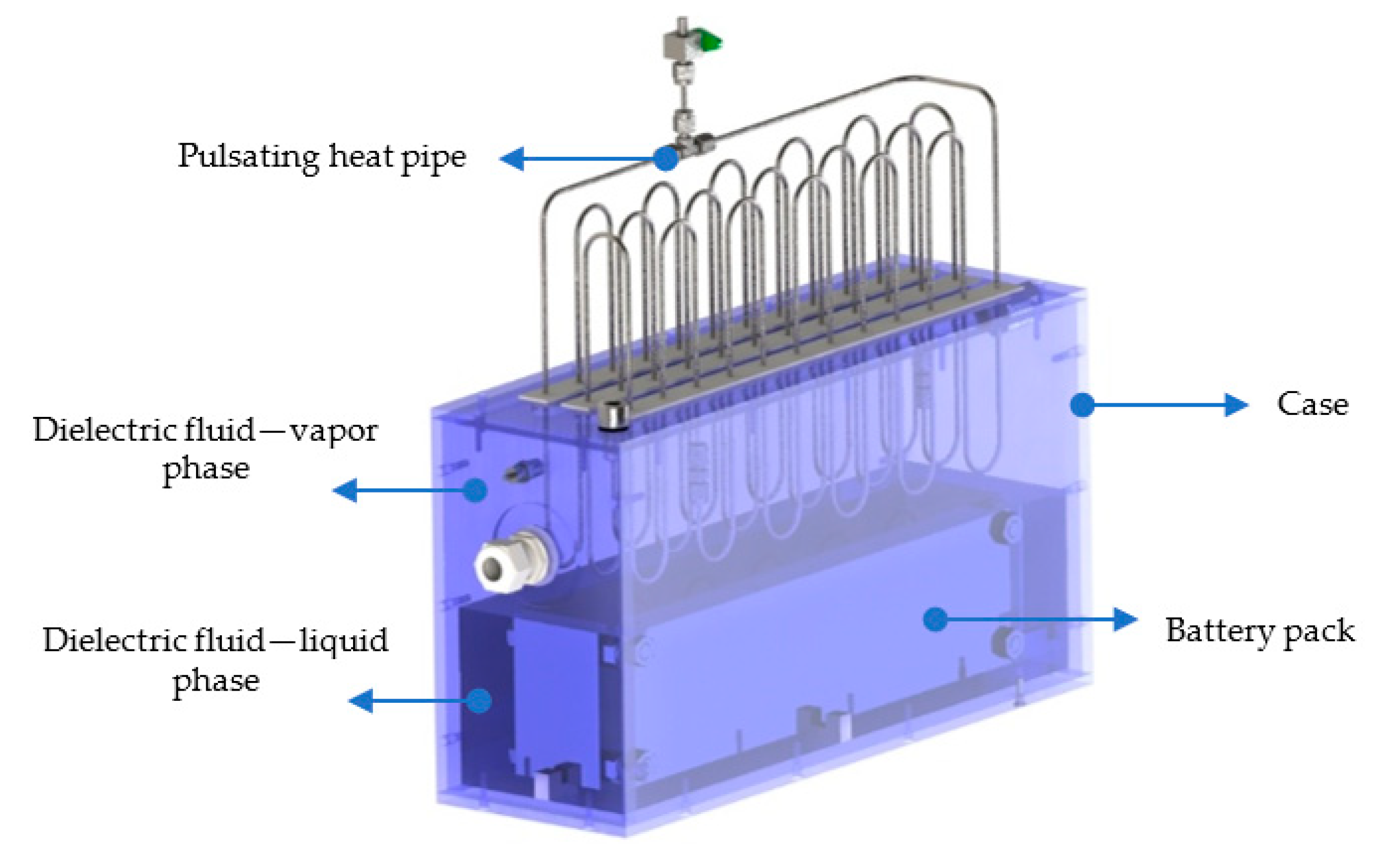
Figure 1. Sketch of BTMS.
Energies 18 04937 g001
Figure 2. Experimental setup.
Energies 18 04937 g002
Figure 3. Heat generated by battery pack during discharge at three different C-rates: 0.5C, 1C, and 2C.
Energies 18 04937 g003
Figure 4. Maximum battery temperature in test at 5 °C under three different C-rates: (a) 0.5C; (b) 1C; and (c) 2C in three different configurations.
Energies 18 04937 g004
Figure 5. Internal pressure in test at 5 °C under three different C-rates: (a) 0.5C; (b) 1C; and (c) 2C.
Energies 18 04937 g005
Figure 6. Maximum battery temperature difference in test at 5 °C under three different C-rates: (a) 0.5C; (b) 1C; and (c) 2C.
Energies 18 04937 g006
Figure 7. Temperatures of the evaporator and condenser sections of the PHP and of the battery in test at 5 °C under 2C discharge.
Energies 18 04937 g007
Figure 8. Maximum battery temperature in test at 20 °C under two different C-rates: (a) 0.5C and (b) 1C.
Energies 18 04937 g008
Figure 9. Internal pressure in test at 20 °C under two different C-rates: (a) 0.5C and (b) 1C in three different configurations.
Energies 18 04937 g009
Figure 10. Maximum battery temperature difference in tests at 20 °C under two different C-rates: (a) 0.5C and (b) 1C.
Energies 18 04937 g010
Figure 11. Maximum battery temperature in test at 20 °C under 2C discharge.
Energies 18 04937 g011
Figure 12. Focus on temperatures of evaporator and condenser PHP sections and of the battery in test at 5 °C under 2C discharge.
Energies 18 04937 g012
Figure 13. Test at 20 °C under 2C discharge: (a) internal pressure and (b) maximum battery temperature difference.
Energies 18 04937 g013
Figure 14. Sketch of BTMS with finned surface at the condenser section of PHP.
Energies 18 04937 g014
Figure 15. Comparison with PHP with finned surface configuration: maximum battery temperature in test at 20 °C under 2C discharge.
Energies 18 04937 g015
Figure 16. Comparison with PHP with finned surface configuration: test at 20 °C under 2C discharge: (a) internal pressure and (b) maximum battery temperature difference.
Energies 18 04937 g016
Figure 17. Maximum battery temperature in test at 25 °C under 2C discharge.
Energies 18 04937 g017
Figure 18. Test at 25 °C under 2C discharge: (a) internal pressure and (b) maximum battery temperature difference.
Energies 18 04937 g018
Table 1. Summary of results.
Natural ConvectionImmersion CoolingImmersion Cooling + PHPImmersion Cooling + PHP + Ext. Surface
TambC-RatesTmax < 40 °CΔT < 5 °CTmax < 40 °CΔT < 5 °CTmax < 40 °CΔT < 5 °CTmax < 40 °CΔT < 5 °C
5 °C0.5C--
1CX--
2CXX--
20 °C0.5C--
1CXX--
2C--X
25 °C0.5C--------
1C--------
2C--X--
Legend: “✓” requirement satisfied, “X” requirement not satisfied, and “-“ test not conducted.
Disclaimer/Publisher’s Note: The statements, opinions and data contained in all publications are solely those of the individual author(s) and contributor(s) and not of MDPI and/or the editor(s). MDPI and/or the editor(s) disclaim responsibility for any injury to people or property resulting from any ideas, methods, instructions or products referred to in the content.